EP2218837A1 - Construction equipment including rear view camera - Google Patents
Construction equipment including rear view camera Download PDFInfo
- Publication number
- EP2218837A1 EP2218837A1 EP10152889A EP10152889A EP2218837A1 EP 2218837 A1 EP2218837 A1 EP 2218837A1 EP 10152889 A EP10152889 A EP 10152889A EP 10152889 A EP10152889 A EP 10152889A EP 2218837 A1 EP2218837 A1 EP 2218837A1
- Authority
- EP
- European Patent Office
- Prior art keywords
- hydraulic pump
- construction equipment
- rear view
- view camera
- detecting
- Prior art date
- Legal status (The legal status is an assumption and is not a legal conclusion. Google has not performed a legal analysis and makes no representation as to the accuracy of the status listed.)
- Withdrawn
Links
- 238000010276 construction Methods 0.000 title claims abstract description 39
- 238000010586 diagram Methods 0.000 description 2
- 230000002708 enhancing effect Effects 0.000 description 2
- 238000007792 addition Methods 0.000 description 1
- 239000000498 cooling water Substances 0.000 description 1
- 238000012986 modification Methods 0.000 description 1
- 230000004048 modification Effects 0.000 description 1
- 238000012544 monitoring process Methods 0.000 description 1
- 238000006467 substitution reaction Methods 0.000 description 1
Images


Classifications
-
- B—PERFORMING OPERATIONS; TRANSPORTING
- B60—VEHICLES IN GENERAL
- B60R—VEHICLES, VEHICLE FITTINGS, OR VEHICLE PARTS, NOT OTHERWISE PROVIDED FOR
- B60R1/00—Optical viewing arrangements; Real-time viewing arrangements for drivers or passengers using optical image capturing systems, e.g. cameras or video systems specially adapted for use in or on vehicles
- B60R1/20—Real-time viewing arrangements for drivers or passengers using optical image capturing systems, e.g. cameras or video systems specially adapted for use in or on vehicles
- B60R1/22—Real-time viewing arrangements for drivers or passengers using optical image capturing systems, e.g. cameras or video systems specially adapted for use in or on vehicles for viewing an area outside the vehicle, e.g. the exterior of the vehicle
- B60R1/23—Real-time viewing arrangements for drivers or passengers using optical image capturing systems, e.g. cameras or video systems specially adapted for use in or on vehicles for viewing an area outside the vehicle, e.g. the exterior of the vehicle with a predetermined field of view
- B60R1/26—Real-time viewing arrangements for drivers or passengers using optical image capturing systems, e.g. cameras or video systems specially adapted for use in or on vehicles for viewing an area outside the vehicle, e.g. the exterior of the vehicle with a predetermined field of view to the rear of the vehicle
-
- E—FIXED CONSTRUCTIONS
- E02—HYDRAULIC ENGINEERING; FOUNDATIONS; SOIL SHIFTING
- E02F—DREDGING; SOIL-SHIFTING
- E02F9/00—Component parts of dredgers or soil-shifting machines, not restricted to one of the kinds covered by groups E02F3/00 - E02F7/00
- E02F9/26—Indicating devices
-
- B—PERFORMING OPERATIONS; TRANSPORTING
- B60—VEHICLES IN GENERAL
- B60R—VEHICLES, VEHICLE FITTINGS, OR VEHICLE PARTS, NOT OTHERWISE PROVIDED FOR
- B60R1/00—Optical viewing arrangements; Real-time viewing arrangements for drivers or passengers using optical image capturing systems, e.g. cameras or video systems specially adapted for use in or on vehicles
- B60R1/02—Rear-view mirror arrangements
- B60R1/08—Rear-view mirror arrangements involving special optical features, e.g. avoiding blind spots, e.g. convex mirrors; Side-by-side associations of rear-view and other mirrors
-
- E—FIXED CONSTRUCTIONS
- E02—HYDRAULIC ENGINEERING; FOUNDATIONS; SOIL SHIFTING
- E02F—DREDGING; SOIL-SHIFTING
- E02F9/00—Component parts of dredgers or soil-shifting machines, not restricted to one of the kinds covered by groups E02F3/00 - E02F7/00
- E02F9/08—Superstructures; Supports for superstructures
- E02F9/0858—Arrangement of component parts installed on superstructures not otherwise provided for, e.g. electric components, fenders, air-conditioning units
-
- E—FIXED CONSTRUCTIONS
- E02—HYDRAULIC ENGINEERING; FOUNDATIONS; SOIL SHIFTING
- E02F—DREDGING; SOIL-SHIFTING
- E02F9/00—Component parts of dredgers or soil-shifting machines, not restricted to one of the kinds covered by groups E02F3/00 - E02F7/00
- E02F9/24—Safety devices, e.g. for preventing overload
-
- E—FIXED CONSTRUCTIONS
- E02—HYDRAULIC ENGINEERING; FOUNDATIONS; SOIL SHIFTING
- E02F—DREDGING; SOIL-SHIFTING
- E02F9/00—Component parts of dredgers or soil-shifting machines, not restricted to one of the kinds covered by groups E02F3/00 - E02F7/00
- E02F9/26—Indicating devices
- E02F9/261—Surveying the work-site to be treated
-
- H—ELECTRICITY
- H04—ELECTRIC COMMUNICATION TECHNIQUE
- H04N—PICTORIAL COMMUNICATION, e.g. TELEVISION
- H04N7/00—Television systems
- H04N7/18—Closed-circuit television [CCTV] systems, i.e. systems in which the video signal is not broadcast
-
- B—PERFORMING OPERATIONS; TRANSPORTING
- B60—VEHICLES IN GENERAL
- B60R—VEHICLES, VEHICLE FITTINGS, OR VEHICLE PARTS, NOT OTHERWISE PROVIDED FOR
- B60R2300/00—Details of viewing arrangements using cameras and displays, specially adapted for use in a vehicle
- B60R2300/70—Details of viewing arrangements using cameras and displays, specially adapted for use in a vehicle characterised by an event-triggered choice to display a specific image among a selection of captured images
Definitions
- the present invention relates to a construction equipment, and more particularly, to a construction equipment including a rear view camera to permit a driver to view rearward traffic conditions.
- FIG. 1 shows a hydraulic excavator including a rear view camera according to a related art.
- the excavator includes a lower driving structure 1; an upper swing structure 2 swingably mounted on the lower driving structure 1; a cabin 3 and an engine 4 mounted on the upper swing structure 2; a working device 11 mounted on the upper swing structure 2 and having a boom 6 driven by a boom cylinder 5, an arm 8 driven by an arm cylinder 6, and a bucket 10 driven by a bucket cylinder 7; a counterweight 12 mounted on a rear side of the upper swing structure 2; and a rear view camera 13 installed a rear surface of the counterweight 12 and displaying a taken image on a monitor placed in the cabin 3.
- a changeover switch for displaying the image taken by the rear view camera is installed, and the changeover switch is turned by a driver.
- the changeover switch since the changeover switch is placed apart from a manipulation unit for operating the equipment, the driver experiences inconvenience in operating the changeover switch during driving.
- the present invention has been made to solve the above-mentioned problems occurring in the prior art while advantages achieved by the prior art are maintained intact.
- One object of the present invention is to provide a construction equipment including a rear view camera to permit a driver to view rearward traffic conditions by displaying a rear image taken by the rear view camera on a monitor installed in a cabin, thereby enhancing driving safety.
- Another object of the present invention is to provide a construction equipment including a rear view camera to permit a driver to turn off an image provided from the rear view camera on a monitor, without manipulating a changeover switch, thereby enhancing driving convenience.
- a construction equipment including a hydraulic pump driven by an engine, a lower driving structure, an upper swing structure swingably mounted on the lower driving structure, a working device mounted on the upper swing structure and having a boom, an arm and a bucket respectively driven by each hydraulic cylinder
- the construction equipment including: a rear view camera installed on a predetermined rear position on the upper swing structure and photographing rearward and lateral sides of the construction equipment in real time; a monitor provided in a cabin mounted on the upper swing structure to display an image output from the rear view camera; a driving detecting unit for detecting driving of the hydraulic pump to output a detected signal; a control unit for displaying the image output from the rear view camera on the monitor when pressure of working oil of the hydraulic pump is more than a set reference pressure; and an image turning-off means for turning off the image displayed on the monitor when a working condition is changed by a driver.
- the driving detecting unit of the hydraulic pump includes a pressure sensor installed in an outlet flow passage of the hydraulic pump and detecting the pressure of the working oil to transmit an electric signal corresponding to the pressure to the control unit.
- the driving detecting unit of the hydraulic pump includes an inclined-angle detecting sensor for detecting an inclined angle of a swash plate of the hydraulic pump to transmit an electric signal corresponding to the inclined angle to the control unit.
- the driving detecting unit of the hydraulic pump includes a sensor for detecting a current value applied to an electronic proportional control valve which controls a pump regulator adjusting the inclined angle of the swash plate so as to control a discharge amount of the hydraulic pump, and the sensor transmits an electric signal corresponding to the current value to the control unit.
- the driving detecting unit of the hydraulic pump includes an engine-revolution detecting sensor for detecting a load variation of the engine to transmit an electric signal corresponding to the control unit.
- the image turning-off means turns off the image output from the rear view camera displayed on the monitor in the case where a manipulation signal for operating the working device is input.
- the image output from the rear view camera is turned off the monitor.
- the construction equipment including the rear view camera includes the following advantages.
- the image of the rear side of the construction equipment taken by the rear view camera is displayed on the monitor provided in the cabin, thereby ensuring the driving safety.
- a screen can display an image wanted by the driver.
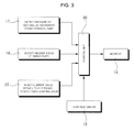
- FIGS. 2 and 3 are block diagrams illustrating a construction equipment including a rear view camera and a control unit of the rear view camera according to a preferred embodiment of the present invention.
- the construction equipment includes a variable capacity hydraulic pump (hereinafter, referred to as hydraulic pump) driven by an engine (E/G), a lower driving structure, an upper swing structure swingably mounted on the lower driving structure, a working device mounted on the upper swing structure and having a boom, an arm and a bucket respectively driven by a hydraulic cylinder.
- hydraulic pump variable capacity hydraulic pump driven by an engine (E/G)
- E/G engine
- lower driving structure lower driving structure
- an upper swing structure swingably mounted on the lower driving structure
- a working device mounted on the upper swing structure and having a boom, an arm and a bucket respectively driven by a hydraulic cylinder.
- the construction equipment further includes a rear view camera (CCD camera) 13 installed on a counterweight 12 which is mounted at a desired rear position on the upper swing structure 2, driven by a driving unit (not shown), and photographing rearward and lateral conditions of the construction equipment in real time; a monitor 14 provided in a cabin 3, which is mounted on the upper swing structure 2, for displaying the image output from the rear view camera 13; a driving detecting unit for detecting driving of a hydraulic pump 15 to output a detected signal; a control unit 30 for displaying the image output from the rear view camera 13 on the monitor 14 when pressure of working oil of the hydraulic pump 15 is more than a reference pressure; and an image turning-off means for turning off the image displayed on the monitor 14 when a working condition is changed by a driver.
- the expression 'change of the operation condition' means that a manipulation signal for operating the working device is input to the control unit 30 during operation.
- the driving detecting unit of the hydraulic pump 15 includes a pressure sensor 17 installed in an outlet flow passage 16 of the hydraulic pump 15 and detecting the pressure of the working oil to transmit an electric signal corresponding to the pressure to the control unit 30.
- the driving detecting unit of the hydraulic pump 15 further includes an inclined-angle detecting sensor 19 for detecting an inclined angle of a swash plate 18 of the hydraulic pump 15 to transmit an electric signal corresponding to the inclined angle to the control unit 30.
- the driving detecting unit of the hydraulic pump 15 includes a sensor 22 for detecting a current value applied to an electronic proportional control valve 21 which controls a pump regulator 20 adjusting the inclined angle of the swash plate 18 so as to control a discharge amount of the hydraulic pump 15.
- the sensor 22 transmits an electric signal corresponding to the current value to the control unit 30.
- the driving detecting unit of the hydraulic pump 15 may include an engine-revolution detecting sensor (not shown) for detecting a load variation of the engine to transmit an electric signal corresponding to the control unit 30.
- the above-described image turning-off means turns off the image output from the rear view camera displayed on the monitor 14 in the case where a manipulation signal for operating the working device 11 such as the boom is input or a manipulation signal for operating a swing device to swing the upper swing structure 2 with respect to the lower driving structure 1 is input.
- the configuration including the lower driving frame 1, the upper swing structure 2, the cabin 3, the working device 11 and the rear view camera 13 is substantially similar to that of the excavator shown in FIG. 1 , and the detained description thereof will be omitted herein, in which like parts are designated by the same reference numerals.
- the electric signal corresponding to the image (i.e., the obstacle positioned at a rear side of the construction equipment) taken by the rear view camera 13 installed on the counterweight 12 to photography the rearward and lateral conditions of the construction equipment in realf time is transmitted to the control unit 30.
- the electric signal corresponding to the pressure of the working oil detected by the pressure sensor 17 installed in the outlet flow passage 16 of the hydraulic pump 15 is transmitted to the control unit 30.
- the pressure of working oil of the hydraulic pump 15 is more than a set reference pressure
- the image output from the rear view camera 13 is displayed on the monitor 14 provided in the cabin 3.
- the driver can turn off the image from the rear view camera 13 on the monitor 14.
- the equipment state means a working state of the devices mounted in the construction equipment, such as various instruments or gauge for displaying temperature of the working oil or temperature of cooling water.
- the image output from the rear view camera 13 can be displayed on the monitor 14 in the cabin 3.
- the image output from the rear view camera 13 can be displayed on the monitor 14 in the cabin 3.
Landscapes
- Engineering & Computer Science (AREA)
- Multimedia (AREA)
- Mining & Mineral Resources (AREA)
- Civil Engineering (AREA)
- General Engineering & Computer Science (AREA)
- Structural Engineering (AREA)
- Mechanical Engineering (AREA)
- Signal Processing (AREA)
- Component Parts Of Construction Machinery (AREA)
- Closed-Circuit Television Systems (AREA)
Abstract
Description
- This application is based on and claims priority from Korean Patent Application No.
10-2009-11523, filed on February 12, 2009 - The present invention relates to a construction equipment, and more particularly, to a construction equipment including a rear view camera to permit a driver to view rearward traffic conditions.
-
FIG. 1 shows a hydraulic excavator including a rear view camera according to a related art. The excavator includes alower driving structure 1; anupper swing structure 2 swingably mounted on thelower driving structure 1; acabin 3 and an engine 4 mounted on theupper swing structure 2; a workingdevice 11 mounted on theupper swing structure 2 and having aboom 6 driven by aboom cylinder 5, anarm 8 driven by anarm cylinder 6, and abucket 10 driven by abucket cylinder 7; acounterweight 12 mounted on a rear side of theupper swing structure 2; and arear view camera 13 installed a rear surface of thecounterweight 12 and displaying a taken image on a monitor placed in thecabin 3. - With the hydraulic excavator including the rear view camera, a changeover switch for displaying the image taken by the rear view camera is installed, and the changeover switch is turned by a driver. In this instance, since the changeover switch is placed apart from a manipulation unit for operating the equipment, the driver experiences inconvenience in operating the changeover switch during driving.
- In addition, in the case where the rear view camera is installed at the rear surface of the counterweight, since the rear view camera is placed at a relatively high position, it is not sufficient to monitor obstacles positioned on the ground around the construction equipment. As a result, the lower driving structure comes in contact with the obstacle, or is trapped in the obstacles, which makes the safety driving in trouble.
- In particular, in the case where the image of the obstacle taken by the rear view camera is displayed on the monitor, it is difficult for the driver to check the actual distance between the construction equipment and the obstacle, which deteriorates practical use.
- Accordingly, the present invention has been made to solve the above-mentioned problems occurring in the prior art while advantages achieved by the prior art are maintained intact.
- One object of the present invention is to provide a construction equipment including a rear view camera to permit a driver to view rearward traffic conditions by displaying a rear image taken by the rear view camera on a monitor installed in a cabin, thereby enhancing driving safety.
- Another object of the present invention is to provide a construction equipment including a rear view camera to permit a driver to turn off an image provided from the rear view camera on a monitor, without manipulating a changeover switch, thereby enhancing driving convenience.
- In order to accomplish these objects, there is provided a construction equipment including a hydraulic pump driven by an engine, a lower driving structure, an upper swing structure swingably mounted on the lower driving structure, a working device mounted on the upper swing structure and having a boom, an arm and a bucket respectively driven by each hydraulic cylinder, the construction equipment including: a rear view camera installed on a predetermined rear position on the upper swing structure and photographing rearward and lateral sides of the construction equipment in real time; a monitor provided in a cabin mounted on the upper swing structure to display an image output from the rear view camera; a driving detecting unit for detecting driving of the hydraulic pump to output a detected signal; a control unit for displaying the image output from the rear view camera on the monitor when pressure of working oil of the hydraulic pump is more than a set reference pressure; and an image turning-off means for turning off the image displayed on the monitor when a working condition is changed by a driver.
- In a preferred embodiment, the driving detecting unit of the hydraulic pump includes a pressure sensor installed in an outlet flow passage of the hydraulic pump and detecting the pressure of the working oil to transmit an electric signal corresponding to the pressure to the control unit.
- In a preferred embodiment, the driving detecting unit of the hydraulic pump includes an inclined-angle detecting sensor for detecting an inclined angle of a swash plate of the hydraulic pump to transmit an electric signal corresponding to the inclined angle to the control unit.
- In a preferred embodiment, the driving detecting unit of the hydraulic pump includes a sensor for detecting a current value applied to an electronic proportional control valve which controls a pump regulator adjusting the inclined angle of the swash plate so as to control a discharge amount of the hydraulic pump, and the sensor transmits an electric signal corresponding to the current value to the control unit.
- In a preferred embodiment, the driving detecting unit of the hydraulic pump includes an engine-revolution detecting sensor for detecting a load variation of the engine to transmit an electric signal corresponding to the control unit.
- The image turning-off means turns off the image output from the rear view camera displayed on the monitor in the case where a manipulation signal for operating the working device is input.
- In a preferred embodiment, if a manipulation signal for operating the working device is input or a manipulation signal for operating the swing device to swing the upper swing structure with respect to the lower driving structure is input, the image output from the rear view camera is turned off the monitor.
- With the above description, the construction equipment including the rear view camera according to a preferred embodiment of the present invention includes the following advantages.
- The image of the rear side of the construction equipment taken by the rear view camera is displayed on the monitor provided in the cabin, thereby ensuring the driving safety.
- Further, since the image output from the rear view camera is turned off from the monitor by selection of the driver, a screen can display an image wanted by the driver.
- The above and other objects, features and advantages of the present invention will be more apparent from the following detailed description taken in conjunction with the accompanying drawings, in which:
-
FIG. 1 is a perspective view illustrating a construction equipment including a rear view camera according to a related art. -
FIG. 2 is a schematic view illustrating a construction equipment including rear view camera according to an embodiment of the present invention. -
FIG. 3 is a block diagram of a control unit for controlling a construction equipment including rear view camera according to an embodiment of the present invention. - Hereinafter, preferred embodiments of the present invention will be described with reference to the accompanying drawings. The matters defined in the description, such as the detailed construction and elements, are nothing but specific details provided to assist those of ordinary skill in the art in a comprehensive understanding of the invention, and thus the present invention is not limited thereto.
-
FIGS. 2 and3 are block diagrams illustrating a construction equipment including a rear view camera and a control unit of the rear view camera according to a preferred embodiment of the present invention. - The construction equipment includes a variable capacity hydraulic pump (hereinafter, referred to as hydraulic pump) driven by an engine (E/G), a lower driving structure, an upper swing structure swingably mounted on the lower driving structure, a working device mounted on the upper swing structure and having a boom, an arm and a bucket respectively driven by a hydraulic cylinder.
- The construction equipment further includes a rear view camera (CCD camera) 13 installed on a
counterweight 12 which is mounted at a desired rear position on theupper swing structure 2, driven by a driving unit (not shown), and photographing rearward and lateral conditions of the construction equipment in real time; amonitor 14 provided in acabin 3, which is mounted on theupper swing structure 2, for displaying the image output from therear view camera 13; a driving detecting unit for detecting driving of ahydraulic pump 15 to output a detected signal; acontrol unit 30 for displaying the image output from therear view camera 13 on themonitor 14 when pressure of working oil of thehydraulic pump 15 is more than a reference pressure; and an image turning-off means for turning off the image displayed on themonitor 14 when a working condition is changed by a driver. In this instance, the expression 'change of the operation condition' means that a manipulation signal for operating the working device is input to thecontrol unit 30 during operation. - The driving detecting unit of the
hydraulic pump 15 includes apressure sensor 17 installed in anoutlet flow passage 16 of thehydraulic pump 15 and detecting the pressure of the working oil to transmit an electric signal corresponding to the pressure to thecontrol unit 30. - The driving detecting unit of the
hydraulic pump 15 further includes an inclined-angle detecting sensor 19 for detecting an inclined angle of aswash plate 18 of thehydraulic pump 15 to transmit an electric signal corresponding to the inclined angle to thecontrol unit 30. - In addition, the driving detecting unit of the
hydraulic pump 15 includes asensor 22 for detecting a current value applied to an electronicproportional control valve 21 which controls apump regulator 20 adjusting the inclined angle of theswash plate 18 so as to control a discharge amount of thehydraulic pump 15. Thesensor 22 transmits an electric signal corresponding to the current value to thecontrol unit 30. - Alternatively, the driving detecting unit of the
hydraulic pump 15 may include an engine-revolution detecting sensor (not shown) for detecting a load variation of the engine to transmit an electric signal corresponding to thecontrol unit 30. - The above-described image turning-off means turns off the image output from the rear view camera displayed on the
monitor 14 in the case where a manipulation signal for operating the workingdevice 11 such as the boom is input or a manipulation signal for operating a swing device to swing theupper swing structure 2 with respect to thelower driving structure 1 is input. - In this instance, the configuration including the
lower driving frame 1, theupper swing structure 2, thecabin 3, theworking device 11 and therear view camera 13 is substantially similar to that of the excavator shown inFIG. 1 , and the detained description thereof will be omitted herein, in which like parts are designated by the same reference numerals. - Next, the application of the construction equipment including the rear view camera according to the embodiment of the present invention will be described with reference to the accompanying drawings.
- As shown in
FIGS. 2 and3 , the electric signal corresponding to the image (i.e., the obstacle positioned at a rear side of the construction equipment) taken by therear view camera 13 installed on thecounterweight 12 to photography the rearward and lateral conditions of the construction equipment in realf time is transmitted to thecontrol unit 30. - The electric signal corresponding to the pressure of the working oil detected by the
pressure sensor 17 installed in theoutlet flow passage 16 of thehydraulic pump 15 is transmitted to thecontrol unit 30. In this instance, when the pressure of working oil of thehydraulic pump 15 is more than a set reference pressure, the image output from therear view camera 13 is displayed on themonitor 14 provided in thecabin 3. - As a result, when the construction equipment is driven, a driver in the
cabin 3 can easily view an obstacle positioned at a blind spot at the rear side of the construction equipment through themonitor 14 to ensure the driving safety. - As described above, in the case where a working condition is changed by the driver monitoring image displayed on the monitor by the rear view camera in the
cabin 3 while the construction equipment is driving, the driver can turn off the image from therear view camera 13 on themonitor 14. - In the case of changing of the working condition described above, that is, in the case where a manipulation signal for operating the
working device 11 such as the boom or the arm is input or a manipulation signal for operating the swing device to swing theupper swing structure 2 with respect to thelower driving structure 1 is input, the image output from therear view camera 13 is turned off themonitor 14. - Meanwhile, in the case where the pressure of the working oil of the
hydraulic pump 15 is lower than the set reference pressure, an equipment state is displayed on themonitor 14. In this instance, the equipment state means a working state of the devices mounted in the construction equipment, such as various instruments or gauge for displaying temperature of the working oil or temperature of cooling water. - If the inclined angle of the
swash plate 18 detected by the inclined-angle detecting sensor 19 is more than a set inclined angle, the image output from therear view camera 13 can be displayed on themonitor 14 in thecabin 3. - In addition, if the electric value applied to the electronic
proportional control valve 21 which controls thepump regulator 20 adjusting the inclined angle of theswash plate 18 so as to control the discharge amount of thehydraulic pump 15 is more than a reference current value, the image output from therear view camera 13 can be displayed on themonitor 14 in thecabin 3. - Although preferred embodiment of the present invention has been described for illustrative purposes, those skilled in the art will appreciate that various modifications, additions and substitutions are possible, without departing from the scope and spirit of the invention as disclosed in the accompanying claims.
Claims (7)
- A construction equipment including a hydraulic pump driven by an engine, a lower driving structure, an upper swing structure swingably mounted on the lower driving structure, a working device mounted on the upper swing structure and having a boom, an arm and a bucket respectively driven by each hydraulic cylinder, the construction equipment comprising:a rear view camera installed on a predetermined rear position on the upper swing structure and photographing rearward and lateral sides of the construction equipment in real time;a monitor provided in a cabin mounted on the upper swing structure to display an image output from the rear view camera;a driving detecting unit for detecting driving of the hydraulic pump to output a detected signal;a control unit for displaying the image output from the rear view camera on the monitor when pressure of working oil of the hydraulic pump is more than a set reference pressure; andan image turning-off means for turning off the image displayed on the monitor when a working condition is changed by a driver.
- The construction equipment according to Claim 1, wherein the driving detecting unit of the hydraulic pump includes a pressure sensor installed in an outlet flow passage of the hydraulic pump and detecting the pressure of the working oil to transmit an electric signal corresponding to the pressure to the control unit.
- The construction equipment according to Claim 1, wherein the driving detecting unit of the hydraulic pump includes an inclined-angle detecting sensor for detecting an inclined angle of a swash plate of the hydraulic pump to transmit an electric signal corresponding to the inclined angle to the control unit.
- The construction equipment according to Claim 1, wherein the driving detecting unit of the hydraulic pump includes a sensor for detecting a current value applied to an electronic proportional control valve which controls a pump regulator adjusting the inclined angle of the swash plate so as to control a discharge amount of the hydraulic pump, and the sensor transmits an electric signal corresponding to the current value to the control unit.
- The construction equipment according to Claim 1, wherein the driving detecting unit of the hydraulic pump includes an engine-revolution detecting sensor for detecting a load variation of the engine to transmit an electric signal corresponding to the control unit.
- The construction equipment according to any one of Claims 1 to 5, wherein the image turning-off means turns off the image output from the rear view camera displayed on the monitor in the case where a manipulation signal for operating the working device is input.
- The construction equipment according to any one of Claims 1 to 5, wherein if a manipulation signal for operating the working device is input or a manipulation signal for operating the swing device to swing the upper swing structure with respect to the lower driving structure is input, the image output from the rear view camera is turned off the monitor.
Applications Claiming Priority (1)
| Application Number | Priority Date | Filing Date | Title |
|---|---|---|---|
| KR1020090011523A KR101078341B1 (en) | 2009-02-12 | 2009-02-12 | construction equipment mounting rear view apparatus |
Publications (1)
| Publication Number | Publication Date |
|---|---|
| EP2218837A1 true EP2218837A1 (en) | 2010-08-18 |
Family
ID=42199509
Family Applications (1)
| Application Number | Title | Priority Date | Filing Date |
|---|---|---|---|
| EP10152889A Withdrawn EP2218837A1 (en) | 2009-02-12 | 2010-02-08 | Construction equipment including rear view camera |
Country Status (5)
| Country | Link |
|---|---|
| US (1) | US8340874B2 (en) |
| EP (1) | EP2218837A1 (en) |
| JP (1) | JP5580614B2 (en) |
| KR (1) | KR101078341B1 (en) |
| CN (1) | CN101806080B (en) |
Families Citing this family (22)
| Publication number | Priority date | Publication date | Assignee | Title |
|---|---|---|---|---|
| US7967371B2 (en) * | 2007-03-20 | 2011-06-28 | Caterpillar Inc. | Machine having camera and mounting strategy therefor |
| US20140293051A1 (en) * | 2011-05-13 | 2014-10-02 | Hitachi Construction Machinery Co., Ltd. | Device for displaying rearward field of view of hydraulic shovel |
| WO2012157379A1 (en) * | 2011-05-13 | 2012-11-22 | 日立建機株式会社 | Device for monitoring area around working machine |
| DE112012004354T5 (en) * | 2011-10-18 | 2014-07-10 | Hitachi Construction Machinery Co., Ltd. | Device for monitoring the environment of machinery |
| JP5888956B2 (en) * | 2011-12-13 | 2016-03-22 | 住友建機株式会社 | Excavator and surrounding image display method of the excavator |
| JP6084613B2 (en) * | 2012-07-19 | 2017-02-22 | 住友建機株式会社 | Excavator |
| JP6073170B2 (en) * | 2013-03-27 | 2017-02-01 | 住友建機株式会社 | Excavator |
| KR20160140113A (en) | 2015-05-29 | 2016-12-07 | 주식회사비엠테크 | Safety System and Method for Monitoring of Construction Equipment |
| CN105421505A (en) * | 2015-12-03 | 2016-03-23 | 天津市中机雄风机械有限公司 | Safe high-precision excavator |
| CN106088197B (en) * | 2016-06-23 | 2018-05-08 | 林正裕 | A kind of highway ditch clears up intelligent robot |
| CN106088196B (en) * | 2016-06-23 | 2018-01-02 | 哈工大机器人集团(哈尔滨)资产经营管理有限公司 | A fully automatic roadbed pavement ditch maintenance machine |
| CN108425397A (en) * | 2016-06-23 | 2018-08-21 | 吴彬 | The working method of the higher highway ditch cleaning intelligent robot of intelligence degree |
| CN106120935B (en) * | 2016-06-23 | 2018-05-11 | 张玲红 | A kind of hydraulic engineering water delivery ditch furrow bank sweeps robot actuator |
| CN106065640B (en) * | 2016-06-23 | 2017-12-19 | 哈工大机器人集团(哈尔滨)资产经营管理有限公司 | A water conservancy engineering ditch wall scraping robot |
| CN106120936B (en) * | 2016-06-23 | 2018-05-11 | 康泽波 | A kind of high speed roadside ditch cleans dredging intelligence equipment and performs manipulator |
| CN106088199B (en) * | 2016-06-23 | 2018-05-11 | 康泽波 | A kind of highway ditch clears up intelligent robot scraper bowl |
| CN106801444A (en) * | 2017-03-29 | 2017-06-06 | 湖南高福星智能科技有限公司 | A kind of energy-saving dozing work machinery of conveniently and fast observing front and back |
| JP6797144B2 (en) * | 2018-03-19 | 2020-12-09 | 株式会社日立建機ティエラ | Construction machinery |
| CN109653267A (en) * | 2019-02-20 | 2019-04-19 | 江苏天煤机电科技有限公司 | Underground excavator and method for digging |
| CN109972688B (en) * | 2019-04-10 | 2021-06-18 | 北京拓疆者智能科技有限公司 | Excavation control method, device and excavator controller |
| GB2610428A (en) * | 2021-09-06 | 2023-03-08 | Bamford Excavators Ltd | A working machine |
| US20240308830A1 (en) * | 2023-03-13 | 2024-09-19 | Oshkosh Corporation | Systems and methods for direction of travel |
Citations (10)
| Publication number | Priority date | Publication date | Assignee | Title |
|---|---|---|---|---|
| JP2001140286A (en) * | 1999-11-10 | 2001-05-22 | Hitachi Constr Mach Co Ltd | Surveillance camera system for construction machinery |
| JP2002275949A (en) * | 2001-03-14 | 2002-09-25 | Hitachi Constr Mach Co Ltd | Information display and display control device for construction machine |
| JP2002294762A (en) * | 2001-03-28 | 2002-10-09 | Kobelco Contstruction Machinery Ltd | Monitor camera device for construction machinery |
| JP2002327470A (en) * | 2001-05-02 | 2002-11-15 | Komatsu Ltd | Work machine display |
| JP2002371595A (en) * | 2001-06-15 | 2002-12-26 | Komatsu Ltd | Construction machinery |
| JP2004346643A (en) * | 2003-05-23 | 2004-12-09 | Sumitomo (Shi) Construction Machinery Manufacturing Co Ltd | Monitoring device for construction machine |
| EP1538267A1 (en) * | 2003-12-02 | 2005-06-08 | Hitachi Construction Machinery Co., Ltd. | Monitoring display device to observe the space behind a construction machine |
| US20050150142A1 (en) * | 2003-08-19 | 2005-07-14 | Komatsu Ltd. | Construction machine |
| US20090009308A1 (en) * | 2005-08-05 | 2009-01-08 | Komatsu Ltd. | Display Device Mounted in Working Vehicle and Display Method For the Display Device |
| KR20090011523A (en) | 2007-07-26 | 2009-02-02 | 삼성코닝정밀유리 주식회사 | Glass Substrates for Fluorescent Lamps and Thermochemical Treatment Methods |
Family Cites Families (9)
| Publication number | Priority date | Publication date | Assignee | Title |
|---|---|---|---|---|
| JPH10140619A (en) | 1996-11-14 | 1998-05-26 | Yutani Heavy Ind Ltd | Rear monitor device of hydraulic shovel |
| KR100892269B1 (en) * | 2001-06-15 | 2009-04-09 | 가부시키가이샤 고마쓰 세이사쿠쇼 | Construction machine |
| JP4082935B2 (en) * | 2002-06-05 | 2008-04-30 | 株式会社小松製作所 | Hybrid construction machine |
| JP4223893B2 (en) * | 2002-10-23 | 2009-02-12 | 株式会社小松製作所 | Control method and control device for hydraulic pump for work machine of work vehicle |
| US7367039B2 (en) * | 2003-05-22 | 2008-04-29 | The Directv Group, Inc. | System and method for evaluating callback functionality in a satellite television network |
| JP4569739B2 (en) * | 2003-11-28 | 2010-10-27 | 日立建機株式会社 | Construction machine display device |
| KR200379923Y1 (en) | 2005-01-11 | 2005-03-24 | 주식회사 더블유플랜 | Safety warning device for construction equipment |
| JP5020528B2 (en) | 2006-04-11 | 2012-09-05 | 株式会社小松製作所 | Construction machine monitoring equipment |
| JP4885833B2 (en) * | 2007-12-10 | 2012-02-29 | 日立建機株式会社 | Construction machinery |
-
2009
- 2009-02-12 KR KR1020090011523A patent/KR101078341B1/en not_active Expired - Fee Related
-
2010
- 2010-02-05 CN CN201010106370.5A patent/CN101806080B/en not_active Expired - Fee Related
- 2010-02-08 EP EP10152889A patent/EP2218837A1/en not_active Withdrawn
- 2010-02-09 US US12/702,766 patent/US8340874B2/en not_active Expired - Fee Related
- 2010-02-10 JP JP2010027175A patent/JP5580614B2/en not_active Expired - Fee Related
Patent Citations (10)
| Publication number | Priority date | Publication date | Assignee | Title |
|---|---|---|---|---|
| JP2001140286A (en) * | 1999-11-10 | 2001-05-22 | Hitachi Constr Mach Co Ltd | Surveillance camera system for construction machinery |
| JP2002275949A (en) * | 2001-03-14 | 2002-09-25 | Hitachi Constr Mach Co Ltd | Information display and display control device for construction machine |
| JP2002294762A (en) * | 2001-03-28 | 2002-10-09 | Kobelco Contstruction Machinery Ltd | Monitor camera device for construction machinery |
| JP2002327470A (en) * | 2001-05-02 | 2002-11-15 | Komatsu Ltd | Work machine display |
| JP2002371595A (en) * | 2001-06-15 | 2002-12-26 | Komatsu Ltd | Construction machinery |
| JP2004346643A (en) * | 2003-05-23 | 2004-12-09 | Sumitomo (Shi) Construction Machinery Manufacturing Co Ltd | Monitoring device for construction machine |
| US20050150142A1 (en) * | 2003-08-19 | 2005-07-14 | Komatsu Ltd. | Construction machine |
| EP1538267A1 (en) * | 2003-12-02 | 2005-06-08 | Hitachi Construction Machinery Co., Ltd. | Monitoring display device to observe the space behind a construction machine |
| US20090009308A1 (en) * | 2005-08-05 | 2009-01-08 | Komatsu Ltd. | Display Device Mounted in Working Vehicle and Display Method For the Display Device |
| KR20090011523A (en) | 2007-07-26 | 2009-02-02 | 삼성코닝정밀유리 주식회사 | Glass Substrates for Fluorescent Lamps and Thermochemical Treatment Methods |
Also Published As
| Publication number | Publication date |
|---|---|
| KR101078341B1 (en) | 2011-11-01 |
| US20100204873A1 (en) | 2010-08-12 |
| JP2010185274A (en) | 2010-08-26 |
| CN101806080B (en) | 2014-06-18 |
| KR20100092238A (en) | 2010-08-20 |
| CN101806080A (en) | 2010-08-18 |
| JP5580614B2 (en) | 2014-08-27 |
| US8340874B2 (en) | 2012-12-25 |
Similar Documents
| Publication | Publication Date | Title |
|---|---|---|
| EP2218837A1 (en) | Construction equipment including rear view camera | |
| US11525244B2 (en) | Display device for shovel | |
| US10087599B2 (en) | Shovel and method of controlling shovel | |
| US9382687B2 (en) | Shovel and method of controlling shovel | |
| US11746497B2 (en) | Shovel | |
| CN105934945B (en) | Display system, display device, and display method of work machine | |
| JP4332028B2 (en) | Display control system | |
| EP3739131B1 (en) | Construction machine | |
| EP2020511A2 (en) | Hydraulic circuit for heavy equipment having variable control device | |
| WO2013099491A1 (en) | Image display device for backhoe | |
| JPWO2016158539A1 (en) | Excavator | |
| US20180295357A1 (en) | Display system of working machine and display method of working machine | |
| JPWO2017047654A1 (en) | Excavator | |
| CN106103854A (en) | The warning display program of the status information display device of Work machine, the warning display packing of Work machine and Work machine | |
| CN103180523B (en) | Working truck | |
| JPWO2017199939A1 (en) | Excavator | |
| JP7114302B2 (en) | Excavator and excavator management device | |
| JP2017210729A (en) | Shovel | |
| JP2006336275A (en) | Display device for construction machine | |
| JP2012188899A (en) | Construction machine | |
| JP2011157751A (en) | Hydraulic work machine | |
| JP6689772B2 (en) | Excavator | |
| JP2021042602A (en) | Excavator | |
| JP7089890B2 (en) | Work vehicle |
Legal Events
| Date | Code | Title | Description |
|---|---|---|---|
| PUAI | Public reference made under article 153(3) epc to a published international application that has entered the european phase |
Free format text: ORIGINAL CODE: 0009012 |
|
| AK | Designated contracting states |
Kind code of ref document: A1 Designated state(s): AT BE BG CH CY CZ DE DK EE ES FI FR GB GR HR HU IE IS IT LI LT LU LV MC MK MT NL NO PL PT RO SE SI SK SM TR |
|
| 17P | Request for examination filed |
Effective date: 20110218 |
|
| R17P | Request for examination filed (corrected) |
Effective date: 20110218 |
|
| GRAP | Despatch of communication of intention to grant a patent |
Free format text: ORIGINAL CODE: EPIDOSNIGR1 |
|
| INTG | Intention to grant announced |
Effective date: 20170927 |
|
| STAA | Information on the status of an ep patent application or granted ep patent |
Free format text: STATUS: THE APPLICATION IS DEEMED TO BE WITHDRAWN |
|
| 18D | Application deemed to be withdrawn |
Effective date: 20180208 |