EP2218596A1 - Vehicle air conditioner with cooling arrangement for a glove box - Google Patents
Vehicle air conditioner with cooling arrangement for a glove box Download PDFInfo
- Publication number
- EP2218596A1 EP2218596A1 EP09290112A EP09290112A EP2218596A1 EP 2218596 A1 EP2218596 A1 EP 2218596A1 EP 09290112 A EP09290112 A EP 09290112A EP 09290112 A EP09290112 A EP 09290112A EP 2218596 A1 EP2218596 A1 EP 2218596A1
- Authority
- EP
- European Patent Office
- Prior art keywords
- hollow profile
- cooling arrangement
- housing
- air
- arrangement according
- Prior art date
- Legal status (The legal status is an assumption and is not a legal conclusion. Google has not performed a legal analysis and makes no representation as to the accuracy of the status listed.)
- Granted
Links
Images
Classifications
-
- B—PERFORMING OPERATIONS; TRANSPORTING
- B60—VEHICLES IN GENERAL
- B60H—ARRANGEMENTS OF HEATING, COOLING, VENTILATING OR OTHER AIR-TREATING DEVICES SPECIALLY ADAPTED FOR PASSENGER OR GOODS SPACES OF VEHICLES
- B60H1/00—Heating, cooling or ventilating [HVAC] devices
- B60H1/00507—Details, e.g. mounting arrangements, desaeration devices
- B60H1/00514—Details of air conditioning housings
- B60H1/0055—Details of air conditioning housings the housing or parts thereof being integrated in other devices, e.g. dashboard
-
- B—PERFORMING OPERATIONS; TRANSPORTING
- B60—VEHICLES IN GENERAL
- B60H—ARRANGEMENTS OF HEATING, COOLING, VENTILATING OR OTHER AIR-TREATING DEVICES SPECIALLY ADAPTED FOR PASSENGER OR GOODS SPACES OF VEHICLES
- B60H1/00—Heating, cooling or ventilating [HVAC] devices
- B60H1/00007—Combined heating, ventilating, or cooling devices
- B60H1/00021—Air flow details of HVAC devices
- B60H1/00035—Air flow details of HVAC devices for sending an air stream of uniform temperature into the passenger compartment
- B60H1/0005—Air flow details of HVAC devices for sending an air stream of uniform temperature into the passenger compartment the air being firstly cooled and subsequently heated or vice versa
-
- B—PERFORMING OPERATIONS; TRANSPORTING
- B60—VEHICLES IN GENERAL
- B60H—ARRANGEMENTS OF HEATING, COOLING, VENTILATING OR OTHER AIR-TREATING DEVICES SPECIALLY ADAPTED FOR PASSENGER OR GOODS SPACES OF VEHICLES
- B60H1/00—Heating, cooling or ventilating [HVAC] devices
- B60H1/00507—Details, e.g. mounting arrangements, desaeration devices
- B60H1/00557—Details of ducts or cables
- B60H1/00564—Details of ducts or cables of air ducts
-
- B—PERFORMING OPERATIONS; TRANSPORTING
- B60—VEHICLES IN GENERAL
- B60H—ARRANGEMENTS OF HEATING, COOLING, VENTILATING OR OTHER AIR-TREATING DEVICES SPECIALLY ADAPTED FOR PASSENGER OR GOODS SPACES OF VEHICLES
- B60H1/00—Heating, cooling or ventilating [HVAC] devices
- B60H1/24—Devices purely for ventilating or where the heating or cooling is irrelevant
- B60H1/241—Devices purely for ventilating or where the heating or cooling is irrelevant characterised by the location of ventilation devices in the vehicle
- B60H1/242—Devices purely for ventilating or where the heating or cooling is irrelevant characterised by the location of ventilation devices in the vehicle located in the front area
-
- B—PERFORMING OPERATIONS; TRANSPORTING
- B60—VEHICLES IN GENERAL
- B60H—ARRANGEMENTS OF HEATING, COOLING, VENTILATING OR OTHER AIR-TREATING DEVICES SPECIALLY ADAPTED FOR PASSENGER OR GOODS SPACES OF VEHICLES
- B60H1/00—Heating, cooling or ventilating [HVAC] devices
- B60H1/00007—Combined heating, ventilating, or cooling devices
- B60H1/00021—Air flow details of HVAC devices
- B60H2001/0015—Temperature regulation
- B60H2001/00164—Temperature regulation with more than one by-pass
Definitions
- the invention relates to a cooling arrangement in connection with a vehicle air conditioning system according to the preamble of claim 1.
- From the DE 103 29 438 A1 is a vehicle with a tempered storage compartment known. Here, coming from the air conditioning, tempered and an air to be supplied air is diverted from the corresponding air duct and fed to the glove box to temper the same.
- the DE 37 39 151 A1 discloses a vehicle with an air conditioner, wherein a cooling box is arranged in the glove box, which is connected via a cold air line to the air conditioner of the air conditioner. In this case, a connection to the housing of the air conditioner is provided.
- a support tube as an air duct is for example from the DE 199 33 531 A1 known.
- crossbeams in vehicles can serve as air ducts to the side jets, the air ducts starting from openings in a housing of an air conditioner, lead the air to the side and / or center nozzles.
- overflowing air ducts are provided as well as for discharging the air from the cross member leading air ducts are provided to the nozzles.
- the same may optionally also be formed integrally with the housing or the nozzle.
- a cooling arrangement in connection with a vehicle air conditioning system, comprising a housing, an evaporator, which is arranged in the housing, temperature flaps for distributing the coming of the evaporator air to a heating channel through a heater and a cold air bypass past the heater, wherein the temperature flaps lie in the cold position on a housing disposed perpendicular to the air flow hollow profile, and in the hollow profile on the air inflow at least one opening is formed, which can come from the evaporator coming, cold air into the interior of the hollow profile.
- a targeted discharge of cold air which cleverly the necessary internals, namely the hollow profile, can serve as contact surfaces for the temperature flaps.
- the cold air from the interior of the hollow profile passes through at least one breakthrough in one of the side walls of the housing in a continuing Air duct, which leads to the glove compartment and / or a cool box in the vehicle interior.
- the hollow profile has an opening on only one side.
- the hollow profile is designed such that it can be used for both left and right-hand drive vehicles.
- the hollow profile particularly preferably arranged on the other side, mirror image of the center plane of the air conditioning, a predetermined breaking point for breaking out of an opening, i. a hollow profile can - depending on breaking out of the opening - be used for both left- and right-hand drive vehicles.
- the hollow profile preferably has air guiding structures on the airflow side, which allow a targeted introduction of the inflowing air into the opening (s) of the hollow profile.
- the air guiding structures can be formed by funnel-like opening ribs which simultaneously form contact surfaces for the temperature flaps. These ribs may be formed of an elastic material, so that with good sealing function impact noise of the flaps can be avoided.
- the hollow profile is formed as a continuous casting and extends in a straight direction from a side wall of the housing to the opposite side wall of the housing.
- the hollow profile has a rectangular profile.
- the hollow profile may of course also be an open hollow profile, which for example has a C-shaped configuration.
- an open hollow profile corresponds to the open side of the opening, which is provided in the case of a closed hollow profile on one side (air inflow side) thereof.
- Essential here is the air-guiding function in the direction of the or the openings in the side walls of the housing.
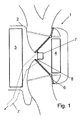
- An air conditioner 1 arranged in a vehicle has an evaporator 3 and a heater 4 arranged in a housing 2, wherein a cold air bypass is arranged to the heater 4.
- a straight air duct 7 extending in a straight direction through the housing 2 is arranged, which is formed by a hollow profile with an approximately square cross-section.
- the hollow profile ends in each case on the side walls of the housing 2, wherein on one side in the corresponding area an opening 2 'is provided in the side wall.
- the hollow profile serves on the one hand as an end stop for the two temperature flaps 6, wherein the same in the operating state "maximum cooling" abut in a funnel-like against the air flow direction extending ribs 8.
- the hollow profile of the discharge serves of cold air from the interior of the housing 2 in the direction of an outside of the housing 2 arranged to be cooled area, in this case a glove box (not shown), for which the air duct 7 via the opening 2 'of the housing 2 in conjunction with a continuing air duct 7' outside of the housing 2, which leads to the cooling area.
- a substantially rectangular opening 7 is formed in the region between the two ribs 8, which in the present case only over a part of the length of the hollow profile in the middle region, exclusively extends on the side of the opening 2 '.
Abstract
Description
Die Erfindung betrifft eine Kühlanordnung in Verbindung mit einer Fahrzeug-Klimaanlage gemäß dem Oberbegriff des Anspruchs 1.The invention relates to a cooling arrangement in connection with a vehicle air conditioning system according to the preamble of
Aus der
Die
Die Nutzung eines Tragrohres als Luftführungskanal ist beispielsweise aus der
Ebenfalls ist bekannt, dass Querträger in Fahrzeugen als Luftkanäle zu den Seitendüsen dienen können, wobei die Luftkanäle ausgehend von Öffnungen in einem Gehäuse einer Klimaanlage die Luft zu den Seiten- und/oder Mitteldüsen führen. Für die Einleitung der von der Klimaanlage kommenden Luft in den Querträger sind vom Gehäuse der Klimaanlage aus verlaufende, überleitende Luftkanäle vorgesehen, wie auch zur Ausleitung der Luft aus dem Querträger ausleitende Luftkanäle zu den Düsen vorgesehen sind. Je nach Länge der überleitenden Luftkanäle können dieselben gegebenenfalls auch einstückig mit dem Gehäuse oder den Düsen ausgebildet sein.It is also known that crossbeams in vehicles can serve as air ducts to the side jets, the air ducts starting from openings in a housing of an air conditioner, lead the air to the side and / or center nozzles. For the introduction of air coming from the air conditioning in the cross member from the housing of the air conditioner extending, overflowing air ducts are provided as well as for discharging the air from the cross member leading air ducts are provided to the nozzles. Depending on the length of the transfer air ducts, the same may optionally also be formed integrally with the housing or the nozzle.
Ausgehend von diesem Stand der Technik, ist es die Aufgabe der vorliegenden Erfindung, eine verbesserte Kühlanordnung bereitzustellen.Based on this prior art, it is the object of the present invention to provide an improved cooling arrangement.
Diese Aufgabe wird erfindungsgemäß durch eine Kühlanordnung mit den Merkmalen des Anspruchs 1 gelöst Vorteilhafte Ausgestaltungen sind Gegenstand der Unteransprüche.This object is achieved by a cooling arrangement with the features of
Erfindungsgemäß ist eine Kühlanordnung in Verbindung mit einer Fahrzeug-Klimaanlage vorgesehen, aufweisend ein Gehäuse, einen Verdampfer, welcher im Gehäuse angeordnet ist, Temperaturklappen zum Verteilen der vom Verdampfer kommenden Luft auf einen Heizkanal durch einen Heizer und einen Kaltluftbypass vorbei am Heizer, wobei die Temperaturklappen in der Kaltstellung an einem im Gehäuse senkrecht zum Luftstrom angeordneten Hohlprofil anliegen, und im Hohlprofil auf der Luftanströmseite mindestens eine Öffnung ausgebildet ist, über welche vom Verdampfer kommende, kalte Luft in das Innere des Hohlprofils eintreten kann. Dies ermöglicht eine gezielte Ausleitung der kalten Luft, wobei auf geschickte Weise die hierfür erforderlichen Einbauten, nämlich das Hohlprofil, als Anlageflächen für die Temperaturklappen dienen können.According to the invention, a cooling arrangement is provided in connection with a vehicle air conditioning system, comprising a housing, an evaporator, which is arranged in the housing, temperature flaps for distributing the coming of the evaporator air to a heating channel through a heater and a cold air bypass past the heater, wherein the temperature flaps lie in the cold position on a housing disposed perpendicular to the air flow hollow profile, and in the hollow profile on the air inflow at least one opening is formed, which can come from the evaporator coming, cold air into the interior of the hollow profile. This allows a targeted discharge of cold air, which cleverly the necessary internals, namely the hollow profile, can serve as contact surfaces for the temperature flaps.
Bevorzugt gelangt die Kaltluft aus dem Inneren des Hohlprofils über mindestens einen Durchbruch in einer der Seitenwände des Gehäuses in einen weiterführenden Luftkanal, welcher zum Handschuhfach und/oder einer Kühlbox im Fahrzeuginnenraum führt.Preferably, the cold air from the interior of the hollow profile passes through at least one breakthrough in one of the side walls of the housing in a continuing Air duct, which leads to the glove compartment and / or a cool box in the vehicle interior.
Besonders bevorzugt weist das Hohlprofil nur auf einer Seite eine Öffnung auf. Bevorzugt ist das Hohlprofil derart ausgebildet, dass es sowohl für linksals auch rechtsgelenkte Fahrzeuge verwendet werden kann. Hierfür weist das Hohlprofil insbesondere bevorzugt auf der anderen Seite, spiegelbildlich zur Mittelebene der Klimaanlage angeordnet, eine Sollbruchstelle für ein Herausbrechen einer Öffnung auf, d.h. ein Hohlprofil kann - je nach Herausbrechen der Öffnung - sowohl für links- als auch rechtsgelenkte Fahrzeuge verwendet werden.Particularly preferably, the hollow profile has an opening on only one side. Preferably, the hollow profile is designed such that it can be used for both left and right-hand drive vehicles. For this purpose, the hollow profile particularly preferably arranged on the other side, mirror image of the center plane of the air conditioning, a predetermined breaking point for breaking out of an opening, i. a hollow profile can - depending on breaking out of the opening - be used for both left- and right-hand drive vehicles.
Das Hohlprofil weist bevorzugt luftanströmseitig Luftleitstrukturen auf, welche ein gezieltes Einleiten der anströmenden Luft in die Öffnung(en) des Hohlprofils ermöglichen. Dabei können die Luftleitstrukturen durch sich trichterartig öffnende Rippen gebildet sein, welche gleichzeitig Anlageflächen für die Temperaturklappen bilden. Diese Rippen können aus einem elastischen Material gebildet sein, so dass bei guter Dichtfunktion Anschlaggeräusche der Klappen vermieden werden können.The hollow profile preferably has air guiding structures on the airflow side, which allow a targeted introduction of the inflowing air into the opening (s) of the hollow profile. In this case, the air guiding structures can be formed by funnel-like opening ribs which simultaneously form contact surfaces for the temperature flaps. These ribs may be formed of an elastic material, so that with good sealing function impact noise of the flaps can be avoided.
Insbesondere bevorzugt ist das Hohlprofil als Stranggussteil ausgebildet und erstreckt sich in gerader Richtung von einer Seitenwand des Gehäuses zur gegenüberliegenden Seitenwand des Gehäuses.Particularly preferably, the hollow profile is formed as a continuous casting and extends in a straight direction from a side wall of the housing to the opposite side wall of the housing.
Gemäß einer bevorzugten Ausführungsform weist das Hohlprofil eine rechteckförmiges Profil auf.According to a preferred embodiment, the hollow profile has a rectangular profile.
Beim Hohlprofil kann es sich natürlich auch um ein offenes Hohlprofil handeln, welches beispielsweise eine C-förmige Gestalt hat. In diesem Fall dient entspricht die offene Seite der Öffnung, weiche im Falle eines geschlossenen Hohlprofils auf einer Seite (Luftanströmseite) desselben vorgesehen ist. Wesentlich ist hierbei die Luftleitfunktion in Richtung des oder der Durchbrüche in den Seitenwänden des Gehäuses.The hollow profile may of course also be an open hollow profile, which for example has a C-shaped configuration. In this case corresponds to the open side of the opening, which is provided in the case of a closed hollow profile on one side (air inflow side) thereof. Essential here is the air-guiding function in the direction of the or the openings in the side walls of the housing.
im Folgenden wird die Erfindung anhand eines Ausführungsbeispiels unter Bezugnahme auf die beiliegende Zeichnung näher erläutert. Hierbei zeigen:
- Fig. 1
- einen Schnitt entlang der Mittellängsebene einer Kühlanordnung gemäß dem Ausführungsbeispiel,
- Fig. 2
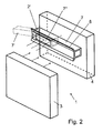
- eine schematische, perspektivische Ansicht der Kühlanordnung von
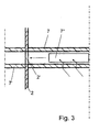
Fig. 1 , und - Fig. 3
- eine schematische Schnittdarstellung durch den die Kaltluft aus- leitenden Bereich der Klimaanlage.
- Fig. 1
- a section along the central longitudinal plane of a cooling arrangement according to the embodiment,
- Fig. 2
- a schematic, perspective view of the cooling arrangement of
Fig. 1 , and - Fig. 3
- a schematic sectional view through the cold air conductive area of the air conditioner.
Eine in einem Fahrzeug angeordnete Klimaanlage 1 weist einen in einem Gehäuse 2 angeordneten Verdampfer 3 und Heizer 4 auf, wobei zum Heizer 4 ein Kaltluftbypass angeordnet ist. Die Verteilung der vom Verdampfer 3 kommenden, kalten Luft auf den Heizer 4 und Kaltluftbypass (vorliegend in Gestalt einer direkten Ausleitung) erfolgt mittels zweier als asymmetrisch zweiflügelige Klappen ausgebildete Temperaturklappen 6.An
Im Bereich vor dem Heizer 4 ist vorliegend ein in gerader Richtung quer durch das Gehäuse 2 verlaufender Luftkanal 7 angeordnet, welcher durch ein Hohlprofil mit annähernd quadratischem Querschnitt gebildet ist. Das Hohlprofil endet jeweils an den Seitenwänden des Gehäuses 2, wobei auf einer Seite im entsprechenden Bereich ein Durchbruch 2' in der Seitenwand vorgesehen ist. Das Hohlprofil dient zum einen als ein Endanschlag für die beiden Temperaturklappen 6, wobei dieselben im Betriebszustand "maximales Kühlen" an sich trichterartig entgegen der Luftströmungsrichtung erstreckenden Rippen 8 anliegen. Zum anderen dient das Hohlprofil der Ausleitung von Kaltluft aus dem Inneren des Gehäuses 2 in Richtung eines außerhalb des Gehäuse 2 angeordneten, zu kühlenden Bereichs, vorliegend eines Handschuhfachs (nicht dargestellt), wofür der Luftkanal 7 über den Durchbruch 2' des Gehäuses 2 in Verbindung mit einem weiterführenden Luftkanal 7' außerhalb des Gehäuses 2 steht, der zum kühlenden Bereich führt. Damit die vom Verdampfer 3 kommende, kalte Luft in den Luftkanal 7 gelangen kann, ist im Bereich zwischen den beiden Rippen 8 luftanströmseitig eine im Wesentlichen rechteckförmige Öffnung 7" ausgebildet, welche sich vorliegend nur über einen Teil der Länge des Hohlprofils im mittleren Bereich, ausschließlich auf der Seite des Durchbruchs 2' erstreckt.In the area in front of the
Durch diese Ausgestaltung wird ein Teil der vom Verdampfer 3 kommenden Luft durch die Öffnung 7" und unterstützt durch die Rippen 8 direkt in den Luftkanal 7 des Hohlprofils eingeleitet, wo sie um 90° umgelenkt und innerhalb des Hohlprofils in Richtung des Durchbruchs 2' in der Seitenwand des Gehäuses 2 geleitet wird, von wo aus sie in den weiterführenden Luftkanal 7' außerhalb des Gehäuses 2 und zum Handschuhfach gelangt.By this configuration, a portion of the air coming from the
Obwohl vorstehend nicht beschrieben, können natürlich auch auf beiden Seiten in den Seitenwänden Durchbrüche mit anschließenden weiterführenden Luftkanälen vorgesehen sein, so dass nicht nur auf der Beifahrerseite ein Handschuhfach sondern auch ein weiterer Bereich, bspw. im Kofferraum angeordnet, gekühlt werden kann.Although not described above, can be provided on both sides in the side walls breakthroughs with subsequent continuing air ducts of course, so that not only on the passenger side, a glove compartment but also another area, for example. In the trunk arranged, can be cooled.
Die Ausgestaltung des Bereichs ab dem Gehäuse 2 kann beispielsweise entsprechend der
- 11
- Klimaanlageair conditioning
- 22
- Gehäusecasing
- 2'2 '
- Durchbruchbreakthrough
- 33
- VerdampferEvaporator
- 44
- Heizerstoker
- 66
- Temperaturklappetemperature flap
- 77
- Luftkanalair duct
- 7'7 '
- Öffnungopening
- 7"7 "
- Luftkanal (außerhalb Gehäuse)Air duct (outside housing)
- 88th
- Ripperib
Claims (12)
Priority Applications (1)
| Application Number | Priority Date | Filing Date | Title |
|---|---|---|---|
| EP09290112A EP2218596B1 (en) | 2009-02-17 | 2009-02-17 | Vehicle air conditioner with cooling arrangement for a glove box |
Applications Claiming Priority (1)
| Application Number | Priority Date | Filing Date | Title |
|---|---|---|---|
| EP09290112A EP2218596B1 (en) | 2009-02-17 | 2009-02-17 | Vehicle air conditioner with cooling arrangement for a glove box |
Publications (2)
| Publication Number | Publication Date |
|---|---|
| EP2218596A1 true EP2218596A1 (en) | 2010-08-18 |
| EP2218596B1 EP2218596B1 (en) | 2012-05-30 |
Family
ID=40848289
Family Applications (1)
| Application Number | Title | Priority Date | Filing Date |
|---|---|---|---|
| EP09290112A Expired - Fee Related EP2218596B1 (en) | 2009-02-17 | 2009-02-17 | Vehicle air conditioner with cooling arrangement for a glove box |
Country Status (1)
| Country | Link |
|---|---|
| EP (1) | EP2218596B1 (en) |
Citations (6)
| Publication number | Priority date | Publication date | Assignee | Title |
|---|---|---|---|---|
| DE3739151A1 (en) | 1986-12-22 | 1988-07-28 | Bayerische Motoren Werke Ag | Cooler box for a motor vehicle |
| DE19933531A1 (en) | 1999-07-16 | 2001-01-18 | Bayerische Motoren Werke Ag | Car with at least one support tube serving as air guidance channel, has at least two elongated support elements on support tube in which outer periphery has niches for support elements |
| DE10329438A1 (en) | 2003-07-01 | 2005-02-17 | Daimlerchrysler Ag | Vehicle climate control to keep a dashboard storage compartment cool on the front passenger side has an air-conditioning device to feed air through it at proper temperatures |
| EP1514708A1 (en) * | 2003-09-12 | 2005-03-16 | Valeo Climatisation | Heating and/or air conditioning device for vehicle compartment, with sophisticated aerothermic management |
| WO2006061956A1 (en) * | 2004-12-10 | 2006-06-15 | Valeo Thermal Systems Japan Corporation | Air conditioner for automobile |
| US20080148752A1 (en) * | 2006-12-21 | 2008-06-26 | Calin Marginean | Vehicle Cooled Instrument Panel Compartment |
-
2009
- 2009-02-17 EP EP09290112A patent/EP2218596B1/en not_active Expired - Fee Related
Patent Citations (6)
| Publication number | Priority date | Publication date | Assignee | Title |
|---|---|---|---|---|
| DE3739151A1 (en) | 1986-12-22 | 1988-07-28 | Bayerische Motoren Werke Ag | Cooler box for a motor vehicle |
| DE19933531A1 (en) | 1999-07-16 | 2001-01-18 | Bayerische Motoren Werke Ag | Car with at least one support tube serving as air guidance channel, has at least two elongated support elements on support tube in which outer periphery has niches for support elements |
| DE10329438A1 (en) | 2003-07-01 | 2005-02-17 | Daimlerchrysler Ag | Vehicle climate control to keep a dashboard storage compartment cool on the front passenger side has an air-conditioning device to feed air through it at proper temperatures |
| EP1514708A1 (en) * | 2003-09-12 | 2005-03-16 | Valeo Climatisation | Heating and/or air conditioning device for vehicle compartment, with sophisticated aerothermic management |
| WO2006061956A1 (en) * | 2004-12-10 | 2006-06-15 | Valeo Thermal Systems Japan Corporation | Air conditioner for automobile |
| US20080148752A1 (en) * | 2006-12-21 | 2008-06-26 | Calin Marginean | Vehicle Cooled Instrument Panel Compartment |
Also Published As
| Publication number | Publication date |
|---|---|
| EP2218596B1 (en) | 2012-05-30 |
Similar Documents
| Publication | Publication Date | Title |
|---|---|---|
| EP1753943B1 (en) | Cooling system | |
| EP3290245A1 (en) | Air vent | |
| EP1930191B1 (en) | Vehicle heating and/or air conditioning device with combined air mixing and distributing damper door | |
| DE102015120290A1 (en) | Air outlet for a vehicle | |
| EP2644419B1 (en) | Vehicle equipped with a housing for holding and regulating the temperature of an electronic device | |
| DE102015109698B4 (en) | Cooling system for a vehicle | |
| EP2062763B1 (en) | Nozzle, especially for a vehicle | |
| DE102016116351A1 (en) | air vents | |
| DE102009050885A1 (en) | air vents | |
| EP1228907B1 (en) | Air conditioning device for a motor vehicle | |
| DE102012013607A1 (en) | Air outlet element, such as air nozzle, for use in air conditioning system for series production of motor vehicle, has air guide device that is provided with air guiding element for deflecting air in direction of certain flow path | |
| DE102004029490A1 (en) | Louver for a heating or air conditioning device comprises several regions arranged directly next to each other and separated by separating walls | |
| EP2048009B1 (en) | Vehicle air conditioning system | |
| EP2072297A1 (en) | Flap, in particular for an air duct | |
| EP2218596B1 (en) | Vehicle air conditioner with cooling arrangement for a glove box | |
| DE102019131554A1 (en) | Air outlet device for the outlet of an air flow | |
| EP1637370B1 (en) | Connection of two air conveying parts of a ventilation system, in particular of a vehicle ventilation system | |
| EP3180223B1 (en) | Rail vehicle having an air-conditioning system | |
| EP2308706A1 (en) | Air duct device | |
| DE102013209871A1 (en) | Rear heating, ventilation and air conditioning system for a motor vehicle | |
| DE102007023230A1 (en) | Cooling air and air baffle guide system for automotive engine bay discharges air through front wheel bays | |
| EP3442844B1 (en) | Air distribution device for a vehicle | |
| DE102019124395B4 (en) | Ventilation device for ventilation of an interior of a vehicle | |
| DE102019123823A1 (en) | VEHICLE WITH AN AIR CONDITIONING DEVICE | |
| DE102007025371B4 (en) | Air conditioning apparatus, in particular for motor vehicles |
Legal Events
| Date | Code | Title | Description |
|---|---|---|---|
| PUAI | Public reference made under article 153(3) epc to a published international application that has entered the european phase |
Free format text: ORIGINAL CODE: 0009012 |
|
| AK | Designated contracting states |
Kind code of ref document: A1 Designated state(s): AT BE BG CH CY CZ DE DK EE ES FI FR GB GR HR HU IE IS IT LI LT LU LV MC MK MT NL NO PL PT RO SE SI SK TR |
|
| AX | Request for extension of the european patent |
Extension state: AL BA RS |
|
| 17P | Request for examination filed |
Effective date: 20110218 |
|
| 17Q | First examination report despatched |
Effective date: 20110310 |
|
| AKX | Designation fees paid |
Designated state(s): DE FR |
|
| GRAP | Despatch of communication of intention to grant a patent |
Free format text: ORIGINAL CODE: EPIDOSNIGR1 |
|
| GRAS | Grant fee paid |
Free format text: ORIGINAL CODE: EPIDOSNIGR3 |
|
| GRAA | (expected) grant |
Free format text: ORIGINAL CODE: 0009210 |
|
| AK | Designated contracting states |
Kind code of ref document: B1 Designated state(s): DE FR |
|
| REG | Reference to a national code |
Ref country code: DE Ref legal event code: R096 Ref document number: 502009003672 Country of ref document: DE Effective date: 20120726 |
|
| PLBE | No opposition filed within time limit |
Free format text: ORIGINAL CODE: 0009261 |
|
| STAA | Information on the status of an ep patent application or granted ep patent |
Free format text: STATUS: NO OPPOSITION FILED WITHIN TIME LIMIT |
|
| 26N | No opposition filed |
Effective date: 20130301 |
|
| REG | Reference to a national code |
Ref country code: DE Ref legal event code: R097 Ref document number: 502009003672 Country of ref document: DE Effective date: 20130301 |
|
| PG25 | Lapsed in a contracting state [announced via postgrant information from national office to epo] |
Ref country code: DE Free format text: LAPSE BECAUSE OF NON-PAYMENT OF DUE FEES Effective date: 20130903 |
|
| REG | Reference to a national code |
Ref country code: FR Ref legal event code: ST Effective date: 20131031 |
|
| REG | Reference to a national code |
Ref country code: DE Ref legal event code: R119 Ref document number: 502009003672 Country of ref document: DE Effective date: 20130903 |
|
| PG25 | Lapsed in a contracting state [announced via postgrant information from national office to epo] |
Ref country code: FR Free format text: LAPSE BECAUSE OF NON-PAYMENT OF DUE FEES Effective date: 20130228 |