EP2218524A1 - Verfahren zur Verwertung von Müll, insbesondere Haus- und Biomüll, und Abwasser und Vorrichtungen zur Durchführung des Verfahrens - Google Patents
Verfahren zur Verwertung von Müll, insbesondere Haus- und Biomüll, und Abwasser und Vorrichtungen zur Durchführung des Verfahrens Download PDFInfo
- Publication number
- EP2218524A1 EP2218524A1 EP20090002014 EP09002014A EP2218524A1 EP 2218524 A1 EP2218524 A1 EP 2218524A1 EP 20090002014 EP20090002014 EP 20090002014 EP 09002014 A EP09002014 A EP 09002014A EP 2218524 A1 EP2218524 A1 EP 2218524A1
- Authority
- EP
- European Patent Office
- Prior art keywords
- waste
- wastewater
- clarification
- washing
- fraction
- Prior art date
- Legal status (The legal status is an assumption and is not a legal conclusion. Google has not performed a legal analysis and makes no representation as to the accuracy of the status listed.)
- Granted
Links
Images


Classifications
-
- B—PERFORMING OPERATIONS; TRANSPORTING
- B09—DISPOSAL OF SOLID WASTE; RECLAMATION OF CONTAMINATED SOIL
- B09B—DISPOSAL OF SOLID WASTE NOT OTHERWISE PROVIDED FOR
- B09B3/00—Destroying solid waste or transforming solid waste into something useful or harmless
- B09B3/30—Destroying solid waste or transforming solid waste into something useful or harmless involving mechanical treatment
- B09B3/35—Shredding, crushing or cutting
-
- C—CHEMISTRY; METALLURGY
- C02—TREATMENT OF WATER, WASTE WATER, SEWAGE, OR SLUDGE
- C02F—TREATMENT OF WATER, WASTE WATER, SEWAGE, OR SLUDGE
- C02F11/00—Treatment of sludge; Devices therefor
- C02F11/02—Biological treatment
- C02F11/04—Anaerobic treatment; Production of methane by such processes
-
- C—CHEMISTRY; METALLURGY
- C02—TREATMENT OF WATER, WASTE WATER, SEWAGE, OR SLUDGE
- C02F—TREATMENT OF WATER, WASTE WATER, SEWAGE, OR SLUDGE
- C02F11/00—Treatment of sludge; Devices therefor
- C02F11/12—Treatment of sludge; Devices therefor by de-watering, drying or thickening
-
- C—CHEMISTRY; METALLURGY
- C02—TREATMENT OF WATER, WASTE WATER, SEWAGE, OR SLUDGE
- C02F—TREATMENT OF WATER, WASTE WATER, SEWAGE, OR SLUDGE
- C02F3/00—Biological treatment of water, waste water, or sewage
-
- C—CHEMISTRY; METALLURGY
- C02—TREATMENT OF WATER, WASTE WATER, SEWAGE, OR SLUDGE
- C02F—TREATMENT OF WATER, WASTE WATER, SEWAGE, OR SLUDGE
- C02F2303/00—Specific treatment goals
- C02F2303/10—Energy recovery
-
- Y—GENERAL TAGGING OF NEW TECHNOLOGICAL DEVELOPMENTS; GENERAL TAGGING OF CROSS-SECTIONAL TECHNOLOGIES SPANNING OVER SEVERAL SECTIONS OF THE IPC; TECHNICAL SUBJECTS COVERED BY FORMER USPC CROSS-REFERENCE ART COLLECTIONS [XRACs] AND DIGESTS
- Y02—TECHNOLOGIES OR APPLICATIONS FOR MITIGATION OR ADAPTATION AGAINST CLIMATE CHANGE
- Y02E—REDUCTION OF GREENHOUSE GAS [GHG] EMISSIONS, RELATED TO ENERGY GENERATION, TRANSMISSION OR DISTRIBUTION
- Y02E50/00—Technologies for the production of fuel of non-fossil origin
- Y02E50/30—Fuel from waste, e.g. synthetic alcohol or diesel
-
- Y—GENERAL TAGGING OF NEW TECHNOLOGICAL DEVELOPMENTS; GENERAL TAGGING OF CROSS-SECTIONAL TECHNOLOGIES SPANNING OVER SEVERAL SECTIONS OF THE IPC; TECHNICAL SUBJECTS COVERED BY FORMER USPC CROSS-REFERENCE ART COLLECTIONS [XRACs] AND DIGESTS
- Y02—TECHNOLOGIES OR APPLICATIONS FOR MITIGATION OR ADAPTATION AGAINST CLIMATE CHANGE
- Y02W—CLIMATE CHANGE MITIGATION TECHNOLOGIES RELATED TO WASTEWATER TREATMENT OR WASTE MANAGEMENT
- Y02W10/00—Technologies for wastewater treatment
- Y02W10/30—Wastewater or sewage treatment systems using renewable energies
Definitions
- the invention relates to a method for recycling of waste, in particular domestic and organic waste, and wastewater and devices for carrying out the method.
- the invention has for its object to remedy this situation.
- a method which is characterized in that the waste and the wastewater are combined, that the waste is washed with the waste water, that the resulting mixture is divided into a solid and a liquid fraction the solid fraction is subjected to a subsequent biological treatment of a biological drying, and that the liquid fraction is passed through the purification stages of a sewage treatment plant for subsequent recovery and biologically purified to obtain sewage sludge.
- the resulting liquid fraction is fed to biological clarification technology and the solid fraction is subjected to biological drying.
- a significant advantage of this method is that the waste is washed out with wastewater while at the same time largely crushing, so that its biological constituents can be fed to the clarification stages of a sewage treatment, while the solid constituents, which have residual biological fractions, are fed to a biological drying.
- Another significant advantage is that for the washing out of the waste pure water is replaced by wastewater, whereby pure water is saved, which is increasingly available in many landscapes to a lesser extent.
- the wet-mechanical separation of the dissolved, predominantly biogenic material from the garbage yields the further advantages which, among other things, not only save landfill capacities, but also make it possible to degrade existing landfills while obtaining valuable materials, energy and landfill surface reactivation as an integral option of the process according to the invention.
- wastewater In addition to the mainly used municipal wastewater, all other wastewater is suitable for waste disposal, such as surface water, leachate from landfills and other waste water, such as those from industry and trade.
- the liquid fraction resulting from the washing of the waste can be supplied as mixed water to the clarification stages of a preferably conventional biological wastewater treatment plant already existing.
- This has the advantage that the system required for carrying out the method according to the invention can be integrated into an existing sewage treatment plant.
- MSA mechanical-biological waste treatment plants
- the resulting fractions in the process are energetically utilized.
- domestic waste and biowaste and wastewater have a high carbon content and thus represent the basis for the production of renewable energy.
- the method according to the invention thus offers the advantage that energy can be generated from the waste and waste water that is treated together.
- the excess sludge accumulated in the sewage treatment plant is fed to a digestion tower for the production of biogas.
- the two biologically dried solid fractions (waste and conventionally conditioned dewatered sewage sludge) of the process are fed to a combined heat and power plant where electrical power and heat are generated.
- the heat generated may be supplied in part as process heat to accelerate the biological drying of the solid fraction of the process.
- a device for processing waste in particular for carrying out the method according to the invention, characterized in that it comprises at least one wash tank with a rotatably mounted therein washing drum, that the wash tank has a waste water inlet and a washing water drain, and that the washing drum is associated with a washing drum filling device for the garbage.
- the wash tank with the washing drum arranged therein can, according to one embodiment, be pivotable about an axis extending transversely to its longitudinal axis by means of a tilting device from an upward filling position into a downward directed emptying position.
- the use is advantageous several wash tanks also because this one of the number of wash tanks proportionally flexible process as well as load control (effect neutral shutdown of individual wash tanks, such as maintenance, precipitation events, utilization of load sinks, about midnight) allowed, as well as a capacity adjustment for the subsequent treatment stages , This is inventively supported by the fact that the wash tanks can be controlled individually from a central office.
- An inventive advantage of this is that individual wash tanks process-neutral, for example, due to maintenance (replacement of the drum, wash tank itself or other parts or general repairs), while the other washing tanks are running from the current overall process can be decoupled.
- This is also advantageous because the process per wash tank is indeed a batch process, however, the process of all wash tanks is an aspired contraining process for the subsequent treatment stages.
- individual wash tanks with different types of waste, such as landfill material can be filled in a controlled manner without negative biological process influence on the cleaning effect of the respective connected treatment stages. The processing capacity and efficiency of such "foreign waste" is directly proportional to the number of wash tanks.
- wash water from the wash tanks either back into the raw sewage collection basin or directly into the sewage treatment stages enables a high-resolution fine fine tuning or corresponding utilization of the treatment stages.
- this fine fine tuning a total load or utilization matched to the optimization of the biogas yield is possible. This is supported by the partial or total return of the wash water to the raw sewage collection basin.
- this material flow control not only brings about a high mixing quality but also has the effect of buffering possibly toxic wastewater constituents from the respective batches of waste laundry in a threefold manner, namely by the microbial biomass already present there, by the dilution, by the method according to the invention increased C concentration in the then used wastewater.
- waste washing and their material flow control is also on the liquid side not only a constant import of waste microbial adapted microorganisms in the biological treatment stages associated, which then has a knock-down effect, but the fine-tuning also allows the control of the concentration of procedural microbial biomass, be it to Utilization of existing clarification capacity or, if necessary, capacity expansion of the treatment stages.
- the washing drum of the waste is crushed at the same time and washed out with the help of waste water.
- the wastewater enriched with the biological components of the refuse runs into the sewage treatment plant.
- the shredded waste contained in the washing drum is poured onto an endless sieve conveyor belt, whereby any remaining larger amounts of water in the refuse can drain through the sieve.
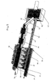
- FIG. 1 is entered in a first embodiment for places without sewage treatment technology or according to disposal-related undersupply in a specially designed according to the invention, independent plant technology, the resulting wastewater "A” in a wash tank 1 and the resulting waste "M” entered into a washing drum 23, located in the wash tank is located.
- the waste contained in the washing drum is mixed with the wastewater and crushed.
- the resulting from the washing and crushing process liquid fraction is fed via a pipe 2 a sewage treatment 4, which has in a known manner the usual sewage treatment wet mechanical separation stages and at least one biological purification stage.
- the secondary sludge or excess sludge resulting in this sewage treatment is fed via a line 15 to a digester 5 in which biogas 6 is produced in a known manner.
- the resulting from the wash tank 1 solid fraction is poured through a line 3 on an endless sieve and conveyor belt 8, can drain on the wash water from the solid fraction.
- the effluent wastewater is collected by a below the sieve conveyor belt 8 arranged Abtropfrinne 9 and fed via a line 11 of the sewage treatment 4.
- the solid fraction passes through a transport line 7 in a plant 10 for biological drying.
- the biological drying of the solid waste fraction is fed from the sewage treatment 4 via a line 17 primary sludge with a dry matter content of about 30%.
- the dried material then passes into a combined heat and power plant 44, in which it is thermally utilized, whereby separately usable heat 45 and current 46 is generated.
- the sewage sludge resulting from the digestion tower 5 is likewise added to the material for biological drying in the plant 10 by means of conditioning (customary conditioning) ( ⁇ 30% dry substance) via a line 18.
- conditioning customary conditioning
- the heat generated in the combined heat and power plant 44 is partially supplied to support the biological drying in the plant 10 material.
- the pure water obtained in the treatment 4 is indicated by 45.
- the Figures 2 and 3 show a washing tank 1 with a coaxial and rotatably mounted washing drum 23 for washing the waste with the addition of waste water in the filling position ( Fig. 2 ) and in the emptying position ( Fig. 3 ).
- the washing drum 23 is cylindrical and has coaxial transverse to its longitudinal axis pivot axes 20, with which it is pivotally mounted between two mutually parallel side walls 21 and 22 of the system. These side walls mark on the one hand the separation to the neighboring washing tank and on the other hand the inventively designed functional autonomy of the wash tank, thus the washing tank's own washing operation.
- the pivot drive for the wash tank 1 is designated 41.
- the electromechanical drive for the washing drum is not shown.
- the washing drum has a hopper 24 at the top to facilitate filling of the refuse.
- the lifting device for example, a trolley with movable crane bridge, with which the refuse is filled into the washing drum is not shown.
- 26 is a feed channel for the wastewater through which the waste water is filled into the washing drum when the wash tank is swung up.
- the mixed water outlet of the wash tank is designated 27. In the raised position of the washing drum according to FIG. 2 the mixed water outlet 27 projects into the inlet funnel of a water discharge pipe 28, through which the washing water is passed into the sewage treatment plant 4.
- FIG. 3 shows the wash tank 1 with the washing drum 23 in the downward pivoting position in which the shredded and washed in the washing drum and washed garbage is poured onto the motor-driven, endless wire conveyor belt 8.
- FIG. 4 shows the washing drum 23 schematically and the arrangement of crushing elements 30 on the inner surface of the washing drum. These and similar comminuting elements can also be designed as cutting. By the element groups, the waste is increasingly crushed during the rotational movement of the washing drum progressively.
- the washing drum has numerous openings, not shown, for discharging the waste water into the washing tank 1.
- the washing drum may be formed as a cage.
- helical mixing and conveying screws 31 are arranged on the inner wall of the washing drum, which cause a constant circulation of the waste-washing mixture in the washing drum during the rotation of the washing drum.
- These built-in elements in the washing drum all carry the washing of the waste with the filled into the wash tank wastewater, which exits through the numerous openings in the washing drum during the washing process from the washing drum and thus enters the wash tank 1.
- FIG. 5 shows the combination of a plant according to FIGS. 1 to 4 with a conventional sewage treatment plant already in practical operation.
- the raw sewage preferably the wastewater of a community, passes as usual via a raw sewage pipe 42 into the existing sewage collection basin 43 of the sewage treatment plant.
- the wastewater is fed via a hoist 32 stepwise in a known manner a rake 33, a sand trap 34 and a primary clarifier 35.
- the wastewater passes through a line 36 in a not shown as usual executed wastewater treatment plant, which includes about a digester for the production of biogas according to the first embodiment.
- this existing sewage treatment plant according to the invention the washing of waste is integrated.
- two groups of five wash tanks 37 are arranged, which are formed with integrated washing drums as in the Figures 2 . 3 and 4 described.
- the wastewater feeds to the wash tanks are designated 38.
- the solid fraction after the washing process from the washing drums on each one endless Siebtransportband 39 poured, of which the solid fraction then a biological drying 10 and a loading device 13, as in the embodiment according to Fig. 1 , is transported to a combined heat and power plant.
- Both the water flowing out of the wash tanks and the water draining from the wire conveyor belt 39 are fed via channels 40 to the sewage collection basin 43 and thus to the existing sewage treatment plant.
Landscapes
- Engineering & Computer Science (AREA)
- Environmental & Geological Engineering (AREA)
- Life Sciences & Earth Sciences (AREA)
- Chemical & Material Sciences (AREA)
- Hydrology & Water Resources (AREA)
- Water Supply & Treatment (AREA)
- Organic Chemistry (AREA)
- Microbiology (AREA)
- Biodiversity & Conservation Biology (AREA)
- Chemical Kinetics & Catalysis (AREA)
- General Chemical & Material Sciences (AREA)
- Oil, Petroleum & Natural Gas (AREA)
- Health & Medical Sciences (AREA)
- Molecular Biology (AREA)
- Processing Of Solid Wastes (AREA)
- Treatment Of Sludge (AREA)
Abstract
Description
- Die Erfindung betrifft ein Verfahren zur Verwertung von Müll, insbesondere Haus- und Biomüll, und Abwasser und Vorrichtungen zur Durchführung des Verfahrens.
- Die bisher strikt getrennt gehaltene Behandlung von Abfall- und Abwasserentsorgung verursacht hohe Verfahrenskosten und hohe Entsorgungskosten. Hausmüll ist die aufkommensstärkste Abfallart. Für die Abfall-Endlagerung sind große Deponiekapazitäten erforderlich, die in immer geringerem Maße zur Verfügung stehen. Bei den Deponien fallen hohe und nachhaltige Nachsorgekosten an, wie Sickerwasser- und andere Emissions-Überwachungsanlagen und Emissions-Gegenmaßnahmen.
- Der Erfindung liegt die Aufgabe zugrunde, hier Abhilfe zu schaffen.
- In Lösung dieser Aufgabe ist ein Verfahren entwickelt worden, das sich dadurch auszeichnet, dass der Müll und das Abwasser zusammengeführt werden, dass der Müll mit dem Abwasser gewaschen wird, dass das so erhaltene Gemisch in eine feste und in eine flüssige Fraktion aufgeteilt wird, dass die feste Fraktion zur nachfolgenden Verwertung einer biologischen Trocknung unterworfen wird, und dass die flüssige Fraktion zur nachfolgenden Verwertung durch die Klärstufen einer Klärtechnik geführt und unter Erhalt von Klärschlamm biologisch gereinigt wird.
- Mit diesem Verfahren wird die Müllentsorgung in die Abwasserentsorgung integriert. Diesem Schritt liegt die Erkenntnis zugrunde, dass alle biologischen Abfallprozesse an die Gegenwart von Wasser gebunden sind und nur im Wasser ablaufen können. Die Biotechnologie des Abfalls ist damit grundsätzlich auch die des Abwassers.
- Nach dem erfindungsgemäßen Verfahren wird die resultierende flüssige Fraktion biologischer Klärtechnik zugeführt und wird die feste Fraktion einer biologischen Trocknung unterworfen. Ein wesentlicher Vorteil dieses Verfahrens besteht darin, dass der Müll bei gleichzeitiger weitgehender Zerkleinerung mit Abwasser ausgewaschen wird, so dass seine biologischen Bestandteile den Klärstufen einer Klärtechnik zugeführt werden können, während die festen Bestandteile, die restliche biologische Anteile aufweisen, einer biologischen Trocknung zugeführt werden. Ein weiterer wesentlicher Vorteil besteht darin, dass für das Auswaschen des Mülls Reinwasser ersetzt wird durch Abwasser, wodurch Reinwasser eingespart wird, das in vielen Landschaften zunehmend in geringerem Maße zur Verfügung steht. Durch die nassmechanische Trennung des gelösten, überwiegend biogenen Materials aus dem Müll ergeben sich die weiteren Vorteile, das unter anderem nicht nur Deponiekapazitäten eingespart werden, sondern vorhandene Deponien unter Gewinnung von Wertstoffen, Energie und Deponieflächenreaktivierung auch abgebaut werden können als integrale Option des erfindungsgemäßen Verfahrens.
- Für die Müllwäsche sind neben dem hauptsächlich verwendeten kommunalen Abwasser alle anderen Abwasser geeignet, wie Oberflächenwasser, Sickerwasser aus Deponien und sonstige Schmutzwasser, wie sie etwa aus Industrie und Handwerk anfallen.
- Nach einer Weiterbildung der Erfindung kann die aus dem Waschen des Mülls hervorgehende flüssige Fraktion als Mischwasser den Klärstufen einer vorzugsweise herkömmlichen bereits bestehenden biologischen Abwasserkläranlage zugeführt werden. Dies ergibt den Vorteil, dass die zur Durchführung des erfindungsgemäßen Verfahrens erforderliche Anlage in eine vorhandene Kläranlage integriert werden kann. Dadurch ergeben als weitere Vorteile eine erhebliche Kostenersparnis, Investitionserübrigung für den Bau und Betrieb mechanisch-biologischer Abfallbehandlungsanlagen (MBA), sowie die Ersparnis an damit einhergehenden Personalkosten, wie auch an Flächen.
- Gemäß Weiterbildungen der Erfindung werden die bei dem Verfahren anfallenden Fraktionen energetisch verwertet. Hausmüll und Bioabfall und Abwasser haben einen hohen Kohlenstoffgehalt und stellen damit die Grundlage zur Gewinnung regenerativer Energien dar. Das erfindungsgemäße Verfahren bietet damit den Vorteil, dass aus dem gemeinsam aufbereiteten Müll und Abwasser Energie erzeugt werden kann. Der in der Klärtechnik anfallende Überschussschlamm wird einem Faulturm zur Gewinnung von Biogas zugeführt. Die zwei biologisch getrockneten festen Fraktionen (Abfall und herkömmlich konditionierter entwässerter Klärschlamm) des Verfahrens werden einem Blockheizkraftwerk zugeführt, in dem elektrischer Strom und Wärme erzeugt werden. Die erzeugte Wärme kann zum Teil als Prozesswärme zur Beschleunigung der biologischen Trocknung der festen Fraktion des Verfahrens zugeführt werden.
- Gemäß einer weiteren Ausbildung der Erfindung, für die auch selbstständiger Schutz beansprucht wird, zeichnet sich eine Vorrichtung zum Aufbereiten von Müll, insbesondere zur Durchführung des erfindungsgemäßen Verfahrens, dadurch aus, dass sie wenigstens einen Waschtank mit einer darin drehbar gelagerten Waschtrommel aufweist, dass der Waschtank einen Abwasser-Zulauf und einen Waschwasser-Ablauf hat, und dass der Waschtrommel eine Waschtrommel-Befülleinrichtung für den Müll zugeordnet ist.
- Der Waschtank mit der darin angeordneten Waschtrommel kann gemäß einer Ausführung um eine quer zu ihrer Längsachse verlaufende Achse mit Hilfe einer Neigungseinrichtung von einer aufwärts gerichteten Befüllstellung in eine abwärts gerichtete Entleerungsstellung schwenkbar sein.
- Entsprechend der Menge des anfallenden Mülls können mehrere Waschtanks nebeneinander aufgestellt werden. Erfindungsgemäß vorteilhaft ist der Einsatz mehrerer Waschtanks auch deshalb, weil dies eine der Anzahl der Waschtanks proportional flexible Prozess- wie auch Laststeuerung (wirkungsneutrale Stilllegung einzelner Waschtanks, etwa wegen Wartungsarbeiten, Niederschlagsereignisse, Auslastung von Lastsenken, etwa zu Mitternacht) erlaubt, wie auch eine Kapazitätsanpassung für die sich anschließenden Klärstufen. Dies wird erfindungsgemäß dadurch gestützt, dass die Waschtanks einzeln von einer Zentrale aus angesteuert werden können.
- Ein erfindungsgemäßer Vorteil davon liegt darin, dass einzelne Waschtanks prozessneutral, etwa wegen Wartungsarbeiten (Auswechselung von Trommel, Waschtank selbst oder anderer Teile oder allgemeine Reparaturen), während des laufenden Betriebs der anderen Waschtanks aus dem laufenden Gesamtprozess entkoppelt werden können. Dies ist auch deswegen vorteilhaft, weil der Prozess pro Waschtank zwar ein Batchprozess ist, der Prozess aller Waschtanks sich indessen als angestrebter Kontiprozess für die sich anschließenden Klärstufen auswirkt. Zudem ergibt sich ein Vorteil dadurch, dass einzelne Waschtanks mit unterschiedlichen Abfallarten, etwa Deponiematerial, kontrolliert befüllt werden können ohne negativen biologischen Prozesseinfluss auf die Reinigungswirkung der jeweilig angeschlossenen Klärstufen. Die Verarbeitungskapazität und -Effizienz von solcherart "Fremdabfall" ist direkt proportional zur Anzahl der Waschtanks. Dies auch deswegen, weil unter anderem auch das biologisch abbauwirksame Verhältnis zwischen BSB (biochemischer Sauerstoffbedarf) und CSB (chemischer Sauerstoffbedarf) zentral leicht steuerbar ist in Form einer steuerbaren Abfallbefüllungs-[halb]automatik für die jeweils einzelnen Waschtanks.
- Durch den wahlweise möglichen Stoffstrom des Waschwassers aus den Waschtanks entweder zurück in das Rohabwassersammelbecken oder direkt in die Klärstufen wird eine hoch auflösende Lastfeinabstimmung bzw. entsprechende Auslastung der Klärstufen ermöglicht. Mit dieser Lastfeinabstimmung ist zudem auch eine auf die Optimierung der Biogasausbeute abgestimmte Gesamtlast bzw. Auslastung möglich. Dies wird gestützt durch die teilweise oder gänzliche Rückführung des Waschwassers in das Rohabwassersammelbecken. Diese Stoffstromlenkung bewirkt in jedem Falle nicht nur eine abbauwirksam hohe Mischungsgüte, sondern wirkt sich zudem als Pufferung gegebenenfalls toxischer Abwasserinhaltsstoffe aus den jeweiligen Chargen der Abfallwäsche aus auf dreierlei Weise, nämlich durch die dort bereits vorhandene mikrobielle Biomasse, durch die Verdünnung, durch die erfindungsgemäß verfahrensbedingt erhöhte C-Konzentration in dem dann zum Einsatz kommenden Abwasser.
- Mit der Abfallwäsche und deren Stoffstromlenkung geht zudem auf die Flüssigseite nicht nur ein ständiger Import abfallbürtig adaptierter Mikroorganismen in die biologischen Klärstufen einher, die sich dort dann abbauwirksam auswirkt, sondern die Feinabstimmung erlaubt auch die Steuerung der Konzentration der verfahrenstechnisch geführten mikrobiellen Biomasse, sei es zur Auslastung vorhandener Klärkapazität oder sei es erforderlichenfalls zum Kapazitätsausbau der Klärstufen.
- In der Waschtrommel wird der Müll zugleich zerkleinert und mit Hilfe des Abwassers ausgewaschen. Nach jedem Waschvorgang läuft das um die biologischen Anteile des Mülls angereicherte Abwasser in die Klärtechnik. Der in der Waschtrommel befindliche zerkleinerte Müll wird auf ein endloses Sieb-Transportband geschüttet, wodurch in dem Müll noch vorhandene größere Wasseranteile durch das Sieb hindurch abtropfen können.
- Ausführungsbeispiele des Verfahrens und der Vorrichtung sind in der Zeichnung dargestellt. Es zeigen:
- Fig.1:
- eine schematische Darstellung des Verfahrens nach einem ersten Ausführungsbeispiel,
- Fig. 2:
- eine perspektivische Ansicht einer Müll-Waschanlage nach der Erfindung in Befüllstellung,
- Fig. 3:
- eine perspektivische Ansicht der Müll-Waschanlage in der Entleerungsstellung,
- Fig. 4:
- eine perspektivische Darstellung der Waschtrommel der Waschanlage,
- Fig. 5:
- eine schematische Darstellung des Verfahrens nach einem zweiten Ausführungsbeispiel.
- Gemäß
Figur 1 wird in einem ersten Ausführungsbeispiel für Orte ohne Abwasserklärtechnik oder entsprechend entsorgungstechnischer Unterversorgung in einer erfindungsgemäßen speziell dafür konzipierten, eigenständigen Anlagentechnik, das anfallende Abwasser "A" in einen Waschtank 1 eingegeben und der anfallende Müll "M" in eine Waschtrommel 23 eingegeben, die sich in dem Waschtank befindet. In dem Waschtank wird der in der Waschtrommel befindliche Müll mit dem Abwasser vermischt und zerkleinert. Die aus dem Wasch- und Zerkleinerungsvorgang anfallende flüssige Fraktion wird über eine Rohrleitung 2 einer Klärtechnik 4 zugeführt, die in bekannter Weise die üblichen abwasserklärtechnisch nassmechanischen Trennstufen und wenigstens eine biologische Reinigungsstufe aufweist. Der in dieser Klärtechnik anfallende Sekundärschlamm bzw. Überschussschlamm wird über eine Leitung 15 einem Faulturm 5 zugeführt, in dem in bekannter Weise Biogas 6 erzeugt wird. - Die aus dem Waschtank 1 anfallende feste Fraktion wird über eine Leitung 3 auf ein endloses Sieb- und Transportband 8 geschüttet, auf dem aus der festen Fraktion Waschwasser abtropfen kann. Das abgelaufene Abwasser wird von einer unter dem Sieb-Transportband 8 angeordneten Abtropfrinne 9 aufgefangen und über eine Leitung 11 der Klärtechnik 4 zugeführt. Von dem Sieb-Transportband 8 gelangt die feste Fraktion über eine Transportlinie 7 in eine Anlage 10 zur biologischen Trocknung. Der biologischen Trocknung der festen Abfallfraktion wird aus der Klärtechnik 4 über eine Leitung 17 Primärschlamm mit einem Trockensubstanzanteil von etwa 30 % zugeführt. Über eine Transportlinie 14 gelangt das getrocknete Material dann in ein Blockheizkraftwerk 44, in dem es thermisch verwertet wird, wodurch separat nutzbare Wärme 45 und Strom 46 erzeugt wird.
- Der aus dem Faulturm 5 anfallende Klärschlamm wird nach klärtechnisch üblicher Konditionierung (~ 30 % Trockensubstanz) über eine Leitung 18 gleichfalls dem in der Anlage 10 zur biologischen Trocknung befindlichen Material zugeschlagen. Die in dem Blockheizkraftwerk 44 anfallende Wärme wird teilweise zur Unterstützung der biologischen Trocknung dem in der Anlage 10 befindlichen Material zugeführt. Das in der Klärtechnik 4 gewonnene Reinwasser ist mit 45 angedeutet.
- Die
Figuren 2 und3 zeigen einen Waschtank 1 mit einer darin koaxial und drehbar gelagerten Waschtrommel 23 zum Waschen des Mülls unter Hinzuführung von Abwasser in der Befüllungsstellung (Fig. 2 ) und in der Entleerungsstellung (Fig. 3 ). Die Waschtrommel 23 ist zylindrisch ausgebildet und hat koaxiale quer zu ihrer Längsachse verlaufende Schwenkachsen 20, mit denen sie zwischen zwei parallel zueinander verlaufenden Seitenwänden 21 und 22 der Anlage schwenkbar gelagert ist. Diese Seitenwände markieren zum einen die Trennung zum Nachbarwaschtank und zum anderen die erfindungsgemäß konzipierte funktionale Autonomie des Waschtanks, mithin den waschtankeigenen Waschbetrieb. Der Schwenkantrieb für den Waschtank 1 ist mit 41 bezeichnet. Der elektromechanische Antrieb für die Waschtrommel ist nicht dargestellt. Die Waschtrommel hat oben einen Einfülltrichter 24 zum Erleichtern des Einfüllens des Mülls. Die Hebevorrichtung, zum Beispiel eine Laufkatze mit beweglicher Kranbrücke, mit welcher der Müll in die Waschtrommel eingefüllt wird, ist nicht dargestellt. 26 ist eine Zulaufrinne für das Abwasser, durch die bei hochgeschwenktem Waschtank das Abwasser in die Waschtrommel eingefüllt wird. Der Mischwasserablauf des Waschtanks ist mit 27 bezeichnet. Bei hochgeschwenkter Stellung der Waschtrommel gemäßFigur 2 ragt der Mischwasserablauf 27 in den Einlauftrichter eines Wasserableitungsrohrs 28 hinein, durch welches das Waschwasser in die Klärtechnik 4 geleitet wird.Figur 3 zeigt den Waschtank 1 mit der Waschtrommel 23 in der abwärts gerichteten Schwenkstellung, in der der in der Waschtrommel zerkleinerte und gewaschene Müll auf das motorgetriebene, endlose Sieb-Transportband 8 geschüttet wird. -
Figur 4 zeigt die Waschtrommel 23 schematisch und die Anordnung von Zerkleinerungselementen 30 an der Innenfläche der Waschtrommel. Diese und ähnliche Zerkleinerungselemente können auch als Schneiden ausgebildet sein. Durch die Element-Gruppen wird der Müll während der Drehbewegung der Waschtrommel fortlaufend zunehmend zerkleinert. Die Waschtrommel hat zahlreiche nicht dargestellte Öffnungen zum Austritt des Abwassers in den Waschtank 1. Dabei kann die Waschtrommel als Käfig ausgebildet sein. Weiterhin sind an der Innenwandung der Waschtrommel schneckenförmig verlaufende Misch- und Förderschnecken 31 angeordnet, die eine ständige Umwälzung des in der Waschtrommel befindlichen Müll-Abwassergemischs während der Rotation der Waschtrommel bewirken. Diese Einbauelemente in der Waschtrommel befördern sämtlich das Waschen des Mülls mit dem in den Waschtank eingefüllten Abwasser, das durch die zahlreichen Öffnungen in der Waschtrommel während des Waschvorganges aus der Waschtrommel austritt und damit in den Waschtank 1 gelangt. -
Figur 5 zeigt die Kombination einer Anlage gemäßFiguren 1 bis 4 mit einer herkömmlichen zuvor bereits im praktischen Betrieb befindlichen AbwasserKläranlage. Das Rohabwasser, vorzugsweise das Abwasser einer Kommune, gelangt wie üblich über eine Rohabwasser-Leitung 42 in das vorhandene Abwassersammelbecken 43 der Kläranlage. Aus dem Abwassersammelbecken wird das Abwasser über ein Hebewerk 32 stufenweise in bekannter Weise einem Rechen 33, einem Sandfang 34 und einem Vorklärbecken 35 zugeführt. Aus dem Vorklärbecken gelangt das Abwasser über eine Leitung 36 in eine nicht dargestellte wie üblich ausgeführte Abwasserreinigungsanlage, die etwa gemäß dem ersten Ausführungsbeispiel auch einen Faulturm zur Erzeugung von Biogas beinhaltet. In diese vorhandene Kläranlage ist das erfindungsgemäße Waschen des Mülls integriert. Dazu sind bei dem Ausführungsbeispiel zwei Gruppen von je fünf Waschtanks 37 angeordnet, die mit integrierten Waschtrommeln so ausgebildet sind, wie in denFiguren 2 ,3 und4 beschrieben. Die Abwasserzuläufe zu den Waschtanks sind mit 38 bezeichnet. Wie in dem ersten Ausführungsbeispiel beschrieben, wird auch hier die feste Fraktion nach dem Waschvorgang aus den Waschtrommeln auf je ein endloses Siebtransportband 39 geschüttet, von denen die feste Fraktion dann über eine biologische Trocknung 10 und eine Beaufschlagungseinrichtung 13, wie bei dem Ausführungsbeispiel gemäßFig. 1 , bis hin zu einem Blockheizkraftwerk befördert wird. Sowohl das aus den Waschtanks abfließende Wasser, als auch das von dem Siebtransportband 39 abtropfende Wasser werden über Rinnen 40 dem Abwassersammelbecken 43 und damit der vorhandenen Kläranlage zugeführt.
Claims (15)
- Verfahren zur Verwertung von Müll, insbesondere Haus- und Biomüll, und Abwasser, vorzugsweise kommunales Abwasser,
dadurch gekennzeichnet,
dass der Müll und das Abwasser zusammengeführt werden,
dass der Müll mit dem Abwasser gewaschen wird,
dass das so erhaltene Gemisch in eine feste und in eine flüssige Fraktion aufgeteilt wird,
dass die feste Fraktion zur nachfolgenden energetischen Verwertung einer biologischen Trocknung unterworfen wird,
und dass die flüssige Fraktion zur nachfolgenden Verwertung durch die Klärstufen einer Klärtechnik geführt und unter Erhalt von Klärschlamm biologisch gereinigt wird. - Verfahren nach Anspruch 1, dadurch gekennzeichnet, dass der Verfahrensablauf mit dem Verfahren einer bereits im Betrieb befindlichen Abwasserkläranlage in der Weise kombiniert wird, dass die flüssige Fraktion den Klärstufen der kommunalen Abwasserkläranlage zugeführt wird.
- Verfahren nach Anspruch 1 oder 2, dadurch gekennzeichnet, dass der Müll vor bzw. während der Verbindung mit dem Abwasser zerkleinert wird.
- Verfahren nach einem der vorhergehenden Ansprüche, dadurch gekennzeichnet, dass Müll von Deponien und Altlasten eingesetzt wird.
- Verfahren nach einem der vorhergehenden Ansprüche, dadurch gekennzeichnet, dass der in der Klärtechnik anfallende Überschussschlamm einem Faulturm zugeführt wird, in dem in bekannter Weise Biogas erzeugt wird.
- Verfahren nach Anspruch 5, dadurch gekennzeichnet, dass der in den Klärstufen anfallende konditionierte Primärschlamm und der in dem Faulturm anfallende konditionierte Klärschlamm der biologischen Trocknung der festen Fraktion zugeführt werden.
- Verfahren nach einem der vorhergehenden Ansprüche, dadurch gekennzeichnet, dass die biologisch getrocknete feste Fraktion unter Erhalt von Energie und Inertstoffen thermisch verwertet wird.
- Verfahren nach Anspruch 7, dadurch gekennzeichnet, dass die biologisch getrocknete Fraktion einem Blockheizkraftwerk als Brennmaterial zugeführt wird.
- Vorrichtung zum Waschen von Müll, insbesondere Haus- und Biomüll, unter Verwendung von Abwasser, insbesondere zur Durchführung des Verfahrens gemäß den Patentansprüchen 1 bis 8,
dadurch gekennzeichnet,
dass sie wenigstens einen Waschtank (1) mit einer darin drehbar gelagerten Waschtrommel (23) aufweist,
dass der Waschtank (1) einen Abwasser-Zulauf (A/38) und einen Mischwasserablauf (2) hat, und
dass der Waschtrommel (23) eine Waschtrommel-Befülleinrichtung für den Müll zugeordnet ist. - Vorrichtung nach Anspruch 9, dadurch gekennzeichnet, dass der Waschtank (1) mit der Waschtrommel (23) um eine quer zu ihrer Längsachse verlaufende Schwenkachse (20) mit Hilfe eines Schwenkantriebs (41) von einer aufwärts gerichteten Befüllstellung in eine abwärts gerichtete Entleerungsstellung schwenkbar ist.
- Vorrichtung nach Anspruch 9 und 10, dadurch gekennzeichnet, dass die Waschtrommel (23) innenseitig angeordnete Zerkleinerungselemente (30) aufweist.
- Vorrichtung nach Anspruch 9 bis 11, dadurch gekennzeichnet, dass an der Innenwand der Waschtrommel (23) wenigstens einer um die Drehachse der Waschtrommel verlaufende Misch- und Förderschnecke (31) angeordnet ist.
- Vorrichtung nach einem der Ansprüche 11 und 12, dadurch gekennzeichnet, dass die Zerkleinerungselemente (30) als Funktionsbleche und/oder Schneidbleche ausgebildet sind und eine Verstellmechanik zum Einstellen der Schneid- und/oder der Förderleistung aufweisen.
- Vorrichtung nach einem der Ansprüche 9 bis 13, dadurch gekennzeichnet, dass der Mischwasserablauf (27) des Waschtanks (1) mit der Eingangsstufe einer Klärtechnik (4) verbunden ist.
- Vorrichtung nach einem der Ansprüche 9 bis 14, dadurch gekennzeichnet, dass sie zur Aufnahme der nach dem Waschvorgang aus der Waschtrommel (23) entleerten festen Fraktion ein endloses Sieb-Transportband (8) aufweist, unter dem sich eine Flüssigkeits-Abtropfrinne (9) befindet, die mit der Eingangsstufe der Klärtechnik verbunden ist.
Priority Applications (1)
| Application Number | Priority Date | Filing Date | Title |
|---|---|---|---|
| EP20090002014 EP2218524B1 (de) | 2009-02-13 | 2009-02-13 | Verfahren zur Verwertung von Haus- und Biomüll, und Abwasser und Vorrichtung zur Durchführung des Verfahrens |
Applications Claiming Priority (1)
| Application Number | Priority Date | Filing Date | Title |
|---|---|---|---|
| EP20090002014 EP2218524B1 (de) | 2009-02-13 | 2009-02-13 | Verfahren zur Verwertung von Haus- und Biomüll, und Abwasser und Vorrichtung zur Durchführung des Verfahrens |
Publications (2)
| Publication Number | Publication Date |
|---|---|
| EP2218524A1 true EP2218524A1 (de) | 2010-08-18 |
| EP2218524B1 EP2218524B1 (de) | 2015-01-07 |
Family
ID=40821702
Family Applications (1)
| Application Number | Title | Priority Date | Filing Date |
|---|---|---|---|
| EP20090002014 Not-in-force EP2218524B1 (de) | 2009-02-13 | 2009-02-13 | Verfahren zur Verwertung von Haus- und Biomüll, und Abwasser und Vorrichtung zur Durchführung des Verfahrens |
Country Status (1)
| Country | Link |
|---|---|
| EP (1) | EP2218524B1 (de) |
Cited By (6)
| Publication number | Priority date | Publication date | Assignee | Title |
|---|---|---|---|---|
| DE102014007318A1 (de) | 2014-05-17 | 2015-11-19 | Hans Joachim Kahle | Verfahren zur Verwertung von Haus- und Biomüll |
| WO2015176697A1 (de) * | 2014-05-17 | 2015-11-26 | Hans Joachim Kahle | Verfahren und vorrichtung zur behandlung und verwendung von bioabfall, restmüll und deponiematerial von hausmülldeponien für biogasanlagen |
| DE102014014445A1 (de) | 2014-09-26 | 2016-03-31 | Hans Joachim Kahle | Vorrichtung zum Waschen von Bioabfall, vorzugsweise Hausmüll, mit einem flüssigen Medium, wie kommunalem Abwasser |
| CN110255788A (zh) * | 2019-07-29 | 2019-09-20 | 马鞍山市新桥工业设计有限公司 | 一种垃圾分拣预处理系统 |
| CN110835219A (zh) * | 2019-11-28 | 2020-02-25 | 天津凯英科技发展股份有限公司 | 市政污泥厌氧消化的增效方法和应用 |
| CN111574192A (zh) * | 2020-05-21 | 2020-08-25 | 洛阳中新能再生能源有限公司 | 一种将多种固体废弃物综合建材化处理的工艺 |
Citations (4)
| Publication number | Priority date | Publication date | Assignee | Title |
|---|---|---|---|---|
| DE3626885A1 (de) * | 1986-08-08 | 1988-02-18 | Steffen Ingenieurgesellschaft | Verfahren und reaktor zur entsorgung von muellverbrennungsrueckstaenden |
| WO1999047473A1 (de) | 1998-03-19 | 1999-09-23 | Wehrle Werk Ag | Verfahren sowie anlage zur behandlung von abfällen |
| US20040002028A1 (en) * | 2002-06-26 | 2004-01-01 | Smith Peter W. | Method for cleaning salt impregnated hog fuel and other bio-mass, and for recovery of waste energy |
| DE102005051111A1 (de) | 2005-10-24 | 2007-04-26 | Hans Joachim Dr. Kahle | Verfahren und Aufbereitungsanlage zum Aufbereiten von Deponiekörpermaterial |
-
2009
- 2009-02-13 EP EP20090002014 patent/EP2218524B1/de not_active Not-in-force
Patent Citations (4)
| Publication number | Priority date | Publication date | Assignee | Title |
|---|---|---|---|---|
| DE3626885A1 (de) * | 1986-08-08 | 1988-02-18 | Steffen Ingenieurgesellschaft | Verfahren und reaktor zur entsorgung von muellverbrennungsrueckstaenden |
| WO1999047473A1 (de) | 1998-03-19 | 1999-09-23 | Wehrle Werk Ag | Verfahren sowie anlage zur behandlung von abfällen |
| US20040002028A1 (en) * | 2002-06-26 | 2004-01-01 | Smith Peter W. | Method for cleaning salt impregnated hog fuel and other bio-mass, and for recovery of waste energy |
| DE102005051111A1 (de) | 2005-10-24 | 2007-04-26 | Hans Joachim Dr. Kahle | Verfahren und Aufbereitungsanlage zum Aufbereiten von Deponiekörpermaterial |
Cited By (8)
| Publication number | Priority date | Publication date | Assignee | Title |
|---|---|---|---|---|
| DE102014007318A1 (de) | 2014-05-17 | 2015-11-19 | Hans Joachim Kahle | Verfahren zur Verwertung von Haus- und Biomüll |
| WO2015176697A1 (de) * | 2014-05-17 | 2015-11-26 | Hans Joachim Kahle | Verfahren und vorrichtung zur behandlung und verwendung von bioabfall, restmüll und deponiematerial von hausmülldeponien für biogasanlagen |
| CN106794468A (zh) * | 2014-05-17 | 2017-05-31 | 汉斯·乔基姆·卡勒 | 用于处理和使用生活垃圾堆的垃圾堆物料、生物废料和残余垃圾用于生物气设备的方法和装置 |
| DE102014014445A1 (de) | 2014-09-26 | 2016-03-31 | Hans Joachim Kahle | Vorrichtung zum Waschen von Bioabfall, vorzugsweise Hausmüll, mit einem flüssigen Medium, wie kommunalem Abwasser |
| CN110255788A (zh) * | 2019-07-29 | 2019-09-20 | 马鞍山市新桥工业设计有限公司 | 一种垃圾分拣预处理系统 |
| CN110255788B (zh) * | 2019-07-29 | 2021-09-28 | 马鞍山市新桥工业设计有限公司 | 一种垃圾分拣预处理系统 |
| CN110835219A (zh) * | 2019-11-28 | 2020-02-25 | 天津凯英科技发展股份有限公司 | 市政污泥厌氧消化的增效方法和应用 |
| CN111574192A (zh) * | 2020-05-21 | 2020-08-25 | 洛阳中新能再生能源有限公司 | 一种将多种固体废弃物综合建材化处理的工艺 |
Also Published As
| Publication number | Publication date |
|---|---|
| EP2218524B1 (de) | 2015-01-07 |
Similar Documents
| Publication | Publication Date | Title |
|---|---|---|
| LU102281B1 (de) | Umfassende Verwertungsvorrichtung für vom Campus stammende Speisereste und Küchenabfälle und Verfahren zu deren Betrieb | |
| DE112011101025B4 (de) | Verfahren zur kombinierten Aufbereitung von Haushaltsabfall und Abwasser | |
| EP1434003B1 (de) | Verfahren und Vorrichtung zur Aufbereitung und Verwertung von festen und flüssigen Abfallgemischen | |
| EP0520172A1 (de) | Aufbereitung von Stoffgemischen, insbesondere von Biomüll, Nassmüll, Restmüll und Gewerbeabfällen, für die anaerobe Vergärung der darin enthaltenen biogen-organischen Bestandteile der Stoffe | |
| EP2218524B1 (de) | Verfahren zur Verwertung von Haus- und Biomüll, und Abwasser und Vorrichtung zur Durchführung des Verfahrens | |
| EP0961762B1 (de) | Abfallbehandlungsverfahren | |
| CN204107978U (zh) | 一种垃圾处理系统 | |
| EP1687093B1 (de) | Verfahren und vorrichtung zur nassmechanischen behandlung eines stoffgemisches, insbesondere von abfall jeder art | |
| DE102010061925A1 (de) | Verfahren zur Reinigung von Abwasser mittels Elektroflockulation sowie Vorrichtung zu seiner Durchführung | |
| EP1753538A2 (de) | Stofflöser, reaktor für hydrolyse und/oder nassrotte und abfallaufbereitungsanlage mit einem derartigen stofflöser und reaktor | |
| DE3835230C2 (de) | Verfahren zur Energiegewinnung durch Müllentgasung und Müllentgasungsanlage | |
| WO2012028628A1 (de) | Einrichtung und verfahren zur gewinnung von öl und/oder fett aus öl- und/oder fetthaltigem wässerigen abfall | |
| EP0937504B1 (de) | Verfahren sowie Vorrichtung zur Durchführung des Verfahrens zur stofflichen Verwertung von Resthausabfällen | |
| EP0181615B1 (de) | Verfahren und Anlage zur Entsorgung und Verwertung von Klärschlamm und Biomüll | |
| DE102005026027A1 (de) | Stofflöser, Reaktor für Hydrolyse und/oder Nassrotte und Abfallaufbereitungsanlage mit einem derartigen Stofflöser und Reaktor | |
| EP1522529A1 (de) | Vorrichtung zum Verwerten von Flüssigabfällen | |
| KR19990017093A (ko) | 유기성 폐기물의 처리장치 및 그 방법 | |
| WO2004043867A2 (de) | Anaerobfermenter | |
| DE102005040839B4 (de) | Kläranlage sowie Verfahren zur Aufbereitung von verunreinigtem Abwasser | |
| AT393826B (de) | Geraet zur anaeroben abwasserbehandlung | |
| EP1289665B1 (de) | Verfahren zur aufbereitung von abfall | |
| WO1999047473A1 (de) | Verfahren sowie anlage zur behandlung von abfällen | |
| WO2014067908A2 (de) | Einrichtung und verfahren zur gewinnung von mindestens einem reinstoff aus biologischen abfall oder biomasse | |
| EP1760047A2 (de) | Verfahren und Vorrichtung zur Aufbereitung von verunreinigtem Abwasser, insbesondere zur Verwertung von Klärschlamm | |
| DE102018120117A1 (de) | Verfahren, Anlage und System zur Gärrestaufbereitung |
Legal Events
| Date | Code | Title | Description |
|---|---|---|---|
| PUAI | Public reference made under article 153(3) epc to a published international application that has entered the european phase |
Free format text: ORIGINAL CODE: 0009012 |
|
| AK | Designated contracting states |
Kind code of ref document: A1 Designated state(s): AT BE BG CH CY CZ DE DK EE ES FI FR GB GR HR HU IE IS IT LI LT LU LV MC MK MT NL NO PL PT RO SE SI SK TR |
|
| AX | Request for extension of the european patent |
Extension state: AL BA RS |
|
| 17P | Request for examination filed |
Effective date: 20110215 |
|
| 17Q | First examination report despatched |
Effective date: 20110330 |
|
| AKX | Designation fees paid |
Designated state(s): AT BE BG CH CY CZ DE DK EE ES FI FR GB GR HR HU IE IS IT LI LT LU LV MC MK MT NL NO PL PT RO SE SI SK TR |
|
| REG | Reference to a national code |
Ref country code: DE Ref legal event code: R079 Ref document number: 502009010439 Country of ref document: DE Free format text: PREVIOUS MAIN CLASS: B09B0003000000 Ipc: C02F0003000000 |
|
| GRAP | Despatch of communication of intention to grant a patent |
Free format text: ORIGINAL CODE: EPIDOSNIGR1 |
|
| RIC1 | Information provided on ipc code assigned before grant |
Ipc: C02F 3/00 20060101AFI20140701BHEP Ipc: C02F 11/12 20060101ALI20140701BHEP Ipc: C02F 11/04 20060101ALI20140701BHEP Ipc: B09B 3/00 20060101ALI20140701BHEP |
|
| INTG | Intention to grant announced |
Effective date: 20140730 |
|
| GRAS | Grant fee paid |
Free format text: ORIGINAL CODE: EPIDOSNIGR3 |
|
| GRAA | (expected) grant |
Free format text: ORIGINAL CODE: 0009210 |
|
| AK | Designated contracting states |
Kind code of ref document: B1 Designated state(s): AT BE BG CH CY CZ DE DK EE ES FI FR GB GR HR HU IE IS IT LI LT LU LV MC MK MT NL NO PL PT RO SE SI SK TR |
|
| REG | Reference to a national code |
Ref country code: GB Ref legal event code: FG4D Free format text: NOT ENGLISH |
|
| REG | Reference to a national code |
Ref country code: CH Ref legal event code: EP |
|
| REG | Reference to a national code |
Ref country code: IE Ref legal event code: FG4D Free format text: LANGUAGE OF EP DOCUMENT: GERMAN |
|
| REG | Reference to a national code |
Ref country code: AT Ref legal event code: REF Ref document number: 705568 Country of ref document: AT Kind code of ref document: T Effective date: 20150215 |
|
| REG | Reference to a national code |
Ref country code: DE Ref legal event code: R096 Ref document number: 502009010439 Country of ref document: DE Effective date: 20150226 |
|
| REG | Reference to a national code |
Ref country code: NL Ref legal event code: VDEP Effective date: 20150107 |
|
| REG | Reference to a national code |
Ref country code: LT Ref legal event code: MG4D |
|
| PG25 | Lapsed in a contracting state [announced via postgrant information from national office to epo] |
Ref country code: BE Free format text: LAPSE BECAUSE OF NON-PAYMENT OF DUE FEES Effective date: 20150228 |
|
| PG25 | Lapsed in a contracting state [announced via postgrant information from national office to epo] |
Ref country code: NO Free format text: LAPSE BECAUSE OF FAILURE TO SUBMIT A TRANSLATION OF THE DESCRIPTION OR TO PAY THE FEE WITHIN THE PRESCRIBED TIME-LIMIT Effective date: 20150407 Ref country code: ES Free format text: LAPSE BECAUSE OF FAILURE TO SUBMIT A TRANSLATION OF THE DESCRIPTION OR TO PAY THE FEE WITHIN THE PRESCRIBED TIME-LIMIT Effective date: 20150107 Ref country code: SE Free format text: LAPSE BECAUSE OF FAILURE TO SUBMIT A TRANSLATION OF THE DESCRIPTION OR TO PAY THE FEE WITHIN THE PRESCRIBED TIME-LIMIT Effective date: 20150107 Ref country code: BG Free format text: LAPSE BECAUSE OF FAILURE TO SUBMIT A TRANSLATION OF THE DESCRIPTION OR TO PAY THE FEE WITHIN THE PRESCRIBED TIME-LIMIT Effective date: 20150407 Ref country code: FI Free format text: LAPSE BECAUSE OF FAILURE TO SUBMIT A TRANSLATION OF THE DESCRIPTION OR TO PAY THE FEE WITHIN THE PRESCRIBED TIME-LIMIT Effective date: 20150107 Ref country code: HR Free format text: LAPSE BECAUSE OF FAILURE TO SUBMIT A TRANSLATION OF THE DESCRIPTION OR TO PAY THE FEE WITHIN THE PRESCRIBED TIME-LIMIT Effective date: 20150107 Ref country code: LT Free format text: LAPSE BECAUSE OF FAILURE TO SUBMIT A TRANSLATION OF THE DESCRIPTION OR TO PAY THE FEE WITHIN THE PRESCRIBED TIME-LIMIT Effective date: 20150107 |
|
| PG25 | Lapsed in a contracting state [announced via postgrant information from national office to epo] |
Ref country code: LV Free format text: LAPSE BECAUSE OF FAILURE TO SUBMIT A TRANSLATION OF THE DESCRIPTION OR TO PAY THE FEE WITHIN THE PRESCRIBED TIME-LIMIT Effective date: 20150107 Ref country code: GR Free format text: LAPSE BECAUSE OF FAILURE TO SUBMIT A TRANSLATION OF THE DESCRIPTION OR TO PAY THE FEE WITHIN THE PRESCRIBED TIME-LIMIT Effective date: 20150408 Ref country code: NL Free format text: LAPSE BECAUSE OF FAILURE TO SUBMIT A TRANSLATION OF THE DESCRIPTION OR TO PAY THE FEE WITHIN THE PRESCRIBED TIME-LIMIT Effective date: 20150107 Ref country code: IS Free format text: LAPSE BECAUSE OF FAILURE TO SUBMIT A TRANSLATION OF THE DESCRIPTION OR TO PAY THE FEE WITHIN THE PRESCRIBED TIME-LIMIT Effective date: 20150507 Ref country code: PL Free format text: LAPSE BECAUSE OF FAILURE TO SUBMIT A TRANSLATION OF THE DESCRIPTION OR TO PAY THE FEE WITHIN THE PRESCRIBED TIME-LIMIT Effective date: 20150107 |
|
| REG | Reference to a national code |
Ref country code: CH Ref legal event code: PL |
|
| REG | Reference to a national code |
Ref country code: DE Ref legal event code: R097 Ref document number: 502009010439 Country of ref document: DE |
|
| PG25 | Lapsed in a contracting state [announced via postgrant information from national office to epo] |
Ref country code: CZ Free format text: LAPSE BECAUSE OF FAILURE TO SUBMIT A TRANSLATION OF THE DESCRIPTION OR TO PAY THE FEE WITHIN THE PRESCRIBED TIME-LIMIT Effective date: 20150107 Ref country code: SK Free format text: LAPSE BECAUSE OF FAILURE TO SUBMIT A TRANSLATION OF THE DESCRIPTION OR TO PAY THE FEE WITHIN THE PRESCRIBED TIME-LIMIT Effective date: 20150107 Ref country code: CH Free format text: LAPSE BECAUSE OF NON-PAYMENT OF DUE FEES Effective date: 20150228 Ref country code: MC Free format text: LAPSE BECAUSE OF FAILURE TO SUBMIT A TRANSLATION OF THE DESCRIPTION OR TO PAY THE FEE WITHIN THE PRESCRIBED TIME-LIMIT Effective date: 20150107 Ref country code: LI Free format text: LAPSE BECAUSE OF NON-PAYMENT OF DUE FEES Effective date: 20150228 Ref country code: RO Free format text: LAPSE BECAUSE OF FAILURE TO SUBMIT A TRANSLATION OF THE DESCRIPTION OR TO PAY THE FEE WITHIN THE PRESCRIBED TIME-LIMIT Effective date: 20150107 Ref country code: DK Free format text: LAPSE BECAUSE OF FAILURE TO SUBMIT A TRANSLATION OF THE DESCRIPTION OR TO PAY THE FEE WITHIN THE PRESCRIBED TIME-LIMIT Effective date: 20150107 Ref country code: EE Free format text: LAPSE BECAUSE OF FAILURE TO SUBMIT A TRANSLATION OF THE DESCRIPTION OR TO PAY THE FEE WITHIN THE PRESCRIBED TIME-LIMIT Effective date: 20150107 |
|
| PLBE | No opposition filed within time limit |
Free format text: ORIGINAL CODE: 0009261 |
|
| STAA | Information on the status of an ep patent application or granted ep patent |
Free format text: STATUS: NO OPPOSITION FILED WITHIN TIME LIMIT |
|
| REG | Reference to a national code |
Ref country code: IE Ref legal event code: MM4A |
|
| REG | Reference to a national code |
Ref country code: FR Ref legal event code: ST Effective date: 20151030 |
|
| 26N | No opposition filed |
Effective date: 20151008 |
|
| GBPC | Gb: european patent ceased through non-payment of renewal fee |
Effective date: 20150407 |
|
| PG25 | Lapsed in a contracting state [announced via postgrant information from national office to epo] |
Ref country code: IT Free format text: LAPSE BECAUSE OF FAILURE TO SUBMIT A TRANSLATION OF THE DESCRIPTION OR TO PAY THE FEE WITHIN THE PRESCRIBED TIME-LIMIT Effective date: 20150107 |
|
| PG25 | Lapsed in a contracting state [announced via postgrant information from national office to epo] |
Ref country code: IE Free format text: LAPSE BECAUSE OF NON-PAYMENT OF DUE FEES Effective date: 20150213 Ref country code: GB Free format text: LAPSE BECAUSE OF NON-PAYMENT OF DUE FEES Effective date: 20150407 |
|
| PG25 | Lapsed in a contracting state [announced via postgrant information from national office to epo] |
Ref country code: SI Free format text: LAPSE BECAUSE OF FAILURE TO SUBMIT A TRANSLATION OF THE DESCRIPTION OR TO PAY THE FEE WITHIN THE PRESCRIBED TIME-LIMIT Effective date: 20150107 Ref country code: FR Free format text: LAPSE BECAUSE OF NON-PAYMENT OF DUE FEES Effective date: 20150309 |
|
| REG | Reference to a national code |
Ref country code: AT Ref legal event code: MM01 Ref document number: 705568 Country of ref document: AT Kind code of ref document: T Effective date: 20150213 |
|
| PG25 | Lapsed in a contracting state [announced via postgrant information from national office to epo] |
Ref country code: AT Free format text: LAPSE BECAUSE OF NON-PAYMENT OF DUE FEES Effective date: 20150213 |
|
| PG25 | Lapsed in a contracting state [announced via postgrant information from national office to epo] |
Ref country code: MT Free format text: LAPSE BECAUSE OF FAILURE TO SUBMIT A TRANSLATION OF THE DESCRIPTION OR TO PAY THE FEE WITHIN THE PRESCRIBED TIME-LIMIT Effective date: 20150107 |
|
| PG25 | Lapsed in a contracting state [announced via postgrant information from national office to epo] |
Ref country code: HU Free format text: LAPSE BECAUSE OF FAILURE TO SUBMIT A TRANSLATION OF THE DESCRIPTION OR TO PAY THE FEE WITHIN THE PRESCRIBED TIME-LIMIT; INVALID AB INITIO Effective date: 20090213 |
|
| PG25 | Lapsed in a contracting state [announced via postgrant information from national office to epo] |
Ref country code: CY Free format text: LAPSE BECAUSE OF FAILURE TO SUBMIT A TRANSLATION OF THE DESCRIPTION OR TO PAY THE FEE WITHIN THE PRESCRIBED TIME-LIMIT Effective date: 20150107 |
|
| PG25 | Lapsed in a contracting state [announced via postgrant information from national office to epo] |
Ref country code: PT Free format text: LAPSE BECAUSE OF FAILURE TO SUBMIT A TRANSLATION OF THE DESCRIPTION OR TO PAY THE FEE WITHIN THE PRESCRIBED TIME-LIMIT Effective date: 20150507 |
|
| PG25 | Lapsed in a contracting state [announced via postgrant information from national office to epo] |
Ref country code: TR Free format text: LAPSE BECAUSE OF FAILURE TO SUBMIT A TRANSLATION OF THE DESCRIPTION OR TO PAY THE FEE WITHIN THE PRESCRIBED TIME-LIMIT Effective date: 20150107 |
|
| PG25 | Lapsed in a contracting state [announced via postgrant information from national office to epo] |
Ref country code: LU Free format text: LAPSE BECAUSE OF NON-PAYMENT OF DUE FEES Effective date: 20150213 |
|
| PG25 | Lapsed in a contracting state [announced via postgrant information from national office to epo] |
Ref country code: MK Free format text: LAPSE BECAUSE OF FAILURE TO SUBMIT A TRANSLATION OF THE DESCRIPTION OR TO PAY THE FEE WITHIN THE PRESCRIBED TIME-LIMIT Effective date: 20150107 |
|
| PGFP | Annual fee paid to national office [announced via postgrant information from national office to epo] |
Ref country code: DE Payment date: 20190207 Year of fee payment: 11 |
|
| REG | Reference to a national code |
Ref country code: DE Ref legal event code: R084 Ref document number: 502009010439 Country of ref document: DE |
|
| REG | Reference to a national code |
Ref country code: DE Ref legal event code: R119 Ref document number: 502009010439 Country of ref document: DE |
|
| PG25 | Lapsed in a contracting state [announced via postgrant information from national office to epo] |
Ref country code: DE Free format text: LAPSE BECAUSE OF NON-PAYMENT OF DUE FEES Effective date: 20200901 |