EP2218472A1 - Device for treating blood outside the body - Google Patents
Device for treating blood outside the body Download PDFInfo
- Publication number
- EP2218472A1 EP2218472A1 EP09001890A EP09001890A EP2218472A1 EP 2218472 A1 EP2218472 A1 EP 2218472A1 EP 09001890 A EP09001890 A EP 09001890A EP 09001890 A EP09001890 A EP 09001890A EP 2218472 A1 EP2218472 A1 EP 2218472A1
- Authority
- EP
- European Patent Office
- Prior art keywords
- radiation source
- intensity
- electromagnetic radiation
- dialysis fluid
- detector
- Prior art date
- Legal status (The legal status is an assumption and is not a legal conclusion. Google has not performed a legal analysis and makes no representation as to the accuracy of the status listed.)
- Granted
Links
- 239000008280 blood Substances 0.000 title claims description 16
- 210000004369 blood Anatomy 0.000 title claims description 16
- 230000005855 radiation Effects 0.000 claims abstract description 65
- 239000000385 dialysis solution Substances 0.000 claims abstract description 41
- 230000005670 electromagnetic radiation Effects 0.000 claims abstract description 34
- 238000010521 absorption reaction Methods 0.000 claims abstract description 28
- 238000000034 method Methods 0.000 claims abstract description 11
- 230000035945 sensitivity Effects 0.000 claims abstract description 7
- 238000011282 treatment Methods 0.000 claims description 24
- 238000001816 cooling Methods 0.000 claims description 10
- 230000008859 change Effects 0.000 claims description 7
- 239000012528 membrane Substances 0.000 claims description 6
- 230000036770 blood supply Effects 0.000 claims description 4
- 230000003287 optical effect Effects 0.000 claims description 4
- XLYOFNOQVPJJNP-UHFFFAOYSA-N water Substances O XLYOFNOQVPJJNP-UHFFFAOYSA-N 0.000 claims description 4
- 230000001105 regulatory effect Effects 0.000 claims description 2
- 239000000126 substance Substances 0.000 description 15
- 210000003734 kidney Anatomy 0.000 description 14
- 230000002485 urinary effect Effects 0.000 description 14
- 230000032683 aging Effects 0.000 description 13
- 239000002699 waste material Substances 0.000 description 12
- 230000009467 reduction Effects 0.000 description 9
- 238000002560 therapeutic procedure Methods 0.000 description 9
- 238000005259 measurement Methods 0.000 description 7
- 238000012959 renal replacement therapy Methods 0.000 description 7
- 230000033228 biological regulation Effects 0.000 description 5
- 231100000614 poison Toxicity 0.000 description 5
- 230000008569 process Effects 0.000 description 5
- 239000003440 toxic substance Substances 0.000 description 5
- 238000000502 dialysis Methods 0.000 description 4
- 230000006641 stabilisation Effects 0.000 description 4
- 238000011105 stabilization Methods 0.000 description 4
- XSQUKJJJFZCRTK-UHFFFAOYSA-N Urea Chemical compound NC(N)=O XSQUKJJJFZCRTK-UHFFFAOYSA-N 0.000 description 3
- 238000011481 absorbance measurement Methods 0.000 description 3
- 239000004202 carbamide Substances 0.000 description 3
- 230000006870 function Effects 0.000 description 3
- 238000012546 transfer Methods 0.000 description 3
- 230000003044 adaptive effect Effects 0.000 description 2
- 230000003247 decreasing effect Effects 0.000 description 2
- 230000001419 dependent effect Effects 0.000 description 2
- 238000009792 diffusion process Methods 0.000 description 2
- 238000010438 heat treatment Methods 0.000 description 2
- 238000004611 spectroscopical analysis Methods 0.000 description 2
- 208000000223 Solitary Kidney Diseases 0.000 description 1
- 230000006978 adaptation Effects 0.000 description 1
- 238000013459 approach Methods 0.000 description 1
- 210000000476 body water Anatomy 0.000 description 1
- 230000001276 controlling effect Effects 0.000 description 1
- 238000001514 detection method Methods 0.000 description 1
- 230000002431 foraging effect Effects 0.000 description 1
- 230000006872 improvement Effects 0.000 description 1
- 230000003907 kidney function Effects 0.000 description 1
- 230000035699 permeability Effects 0.000 description 1
- 238000009256 replacement therapy Methods 0.000 description 1
- 238000012552 review Methods 0.000 description 1
- 150000003839 salts Chemical class 0.000 description 1
- 238000004659 sterilization and disinfection Methods 0.000 description 1
- 230000001052 transient effect Effects 0.000 description 1
Images


Classifications
-
- A—HUMAN NECESSITIES
- A61—MEDICAL OR VETERINARY SCIENCE; HYGIENE
- A61M—DEVICES FOR INTRODUCING MEDIA INTO, OR ONTO, THE BODY; DEVICES FOR TRANSDUCING BODY MEDIA OR FOR TAKING MEDIA FROM THE BODY; DEVICES FOR PRODUCING OR ENDING SLEEP OR STUPOR
- A61M1/00—Suction or pumping devices for medical purposes; Devices for carrying-off, for treatment of, or for carrying-over, body-liquids; Drainage systems
- A61M1/14—Dialysis systems; Artificial kidneys; Blood oxygenators ; Reciprocating systems for treatment of body fluids, e.g. single needle systems for hemofiltration or pheresis
- A61M1/16—Dialysis systems; Artificial kidneys; Blood oxygenators ; Reciprocating systems for treatment of body fluids, e.g. single needle systems for hemofiltration or pheresis with membranes
- A61M1/1601—Control or regulation
- A61M1/1603—Regulation parameters
- A61M1/1605—Physical characteristics of the dialysate fluid
- A61M1/1609—Physical characteristics of the dialysate fluid after use, i.e. downstream of dialyser
-
- G—PHYSICS
- G01—MEASURING; TESTING
- G01J—MEASUREMENT OF INTENSITY, VELOCITY, SPECTRAL CONTENT, POLARISATION, PHASE OR PULSE CHARACTERISTICS OF INFRARED, VISIBLE OR ULTRAVIOLET LIGHT; COLORIMETRY; RADIATION PYROMETRY
- G01J3/00—Spectrometry; Spectrophotometry; Monochromators; Measuring colours
- G01J3/02—Details
- G01J3/027—Control of working procedures of a spectrometer; Failure detection; Bandwidth calculation
-
- G—PHYSICS
- G01—MEASURING; TESTING
- G01J—MEASUREMENT OF INTENSITY, VELOCITY, SPECTRAL CONTENT, POLARISATION, PHASE OR PULSE CHARACTERISTICS OF INFRARED, VISIBLE OR ULTRAVIOLET LIGHT; COLORIMETRY; RADIATION PYROMETRY
- G01J3/00—Spectrometry; Spectrophotometry; Monochromators; Measuring colours
- G01J3/02—Details
- G01J3/0286—Constructional arrangements for compensating for fluctuations caused by temperature, humidity or pressure, or using cooling or temperature stabilization of parts of the device; Controlling the atmosphere inside a spectrometer, e.g. vacuum
-
- G—PHYSICS
- G01—MEASURING; TESTING
- G01J—MEASUREMENT OF INTENSITY, VELOCITY, SPECTRAL CONTENT, POLARISATION, PHASE OR PULSE CHARACTERISTICS OF INFRARED, VISIBLE OR ULTRAVIOLET LIGHT; COLORIMETRY; RADIATION PYROMETRY
- G01J3/00—Spectrometry; Spectrophotometry; Monochromators; Measuring colours
- G01J3/28—Investigating the spectrum
- G01J3/42—Absorption spectrometry; Double beam spectrometry; Flicker spectrometry; Reflection spectrometry
-
- G—PHYSICS
- G01—MEASURING; TESTING
- G01N—INVESTIGATING OR ANALYSING MATERIALS BY DETERMINING THEIR CHEMICAL OR PHYSICAL PROPERTIES
- G01N21/00—Investigating or analysing materials by the use of optical means, i.e. using sub-millimetre waves, infrared, visible or ultraviolet light
- G01N21/17—Systems in which incident light is modified in accordance with the properties of the material investigated
- G01N21/25—Colour; Spectral properties, i.e. comparison of effect of material on the light at two or more different wavelengths or wavelength bands
- G01N21/27—Colour; Spectral properties, i.e. comparison of effect of material on the light at two or more different wavelengths or wavelength bands using photo-electric detection ; circuits for computing concentration
- G01N21/274—Calibration, base line adjustment, drift correction
- G01N21/278—Constitution of standards
-
- A—HUMAN NECESSITIES
- A61—MEDICAL OR VETERINARY SCIENCE; HYGIENE
- A61M—DEVICES FOR INTRODUCING MEDIA INTO, OR ONTO, THE BODY; DEVICES FOR TRANSDUCING BODY MEDIA OR FOR TAKING MEDIA FROM THE BODY; DEVICES FOR PRODUCING OR ENDING SLEEP OR STUPOR
- A61M2205/00—General characteristics of the apparatus
- A61M2205/33—Controlling, regulating or measuring
- A61M2205/3306—Optical measuring means
- A61M2205/3313—Optical measuring means used specific wavelengths
-
- A—HUMAN NECESSITIES
- A61—MEDICAL OR VETERINARY SCIENCE; HYGIENE
- A61M—DEVICES FOR INTRODUCING MEDIA INTO, OR ONTO, THE BODY; DEVICES FOR TRANSDUCING BODY MEDIA OR FOR TAKING MEDIA FROM THE BODY; DEVICES FOR PRODUCING OR ENDING SLEEP OR STUPOR
- A61M2205/00—General characteristics of the apparatus
- A61M2205/33—Controlling, regulating or measuring
- A61M2205/3317—Electromagnetic, inductive or dielectric measuring means
-
- A—HUMAN NECESSITIES
- A61—MEDICAL OR VETERINARY SCIENCE; HYGIENE
- A61M—DEVICES FOR INTRODUCING MEDIA INTO, OR ONTO, THE BODY; DEVICES FOR TRANSDUCING BODY MEDIA OR FOR TAKING MEDIA FROM THE BODY; DEVICES FOR PRODUCING OR ENDING SLEEP OR STUPOR
- A61M2205/00—General characteristics of the apparatus
- A61M2205/33—Controlling, regulating or measuring
- A61M2205/3324—PH measuring means
-
- A—HUMAN NECESSITIES
- A61—MEDICAL OR VETERINARY SCIENCE; HYGIENE
- A61M—DEVICES FOR INTRODUCING MEDIA INTO, OR ONTO, THE BODY; DEVICES FOR TRANSDUCING BODY MEDIA OR FOR TAKING MEDIA FROM THE BODY; DEVICES FOR PRODUCING OR ENDING SLEEP OR STUPOR
- A61M2205/00—General characteristics of the apparatus
- A61M2205/33—Controlling, regulating or measuring
- A61M2205/3368—Temperature
-
- A—HUMAN NECESSITIES
- A61—MEDICAL OR VETERINARY SCIENCE; HYGIENE
- A61M—DEVICES FOR INTRODUCING MEDIA INTO, OR ONTO, THE BODY; DEVICES FOR TRANSDUCING BODY MEDIA OR FOR TAKING MEDIA FROM THE BODY; DEVICES FOR PRODUCING OR ENDING SLEEP OR STUPOR
- A61M2205/00—General characteristics of the apparatus
- A61M2205/50—General characteristics of the apparatus with microprocessors or computers
Definitions
- the invention relates to a device for extracorporeal blood treatment according to the preamble of patent claim 1.
- waste products, including toxic substances are eliminated by renal replacement therapy, the patient's blood being delivered via a blood supply line from the patient to the artificial kidney or dialyzer.
- the patient's blood is brought into contact with dialysis fluid via a semipermeable membrane.
- the dialysis fluid contains different salts in a concentration such that the waste products, including the toxic substances, are conducted by diffusion and convection through the membrane from the patient's blood to the dialysis fluid.
- the blood thus purified from the waste products is returned to the bloodstream of the patient via a blood discharge line connected to the dialyzer.
- Kt / V is a parameter for determining the effectiveness of renal replacement therapy, whereby the clearance K stands for the volume flow of the purified urinary substances, t for the treatment time and V for the distribution volume of the patient. Both K and V are each related to the respective waste product.
- renal replacement therapy efficiency is described as urea waste, such that K describes the urea clearance and V the patient's urea distribution volume, which is essentially the body water of the patient.
- the object of the invention is therefore to develop a device according to the preamble of claim 1 such that a reliable and unaltered statement about the Kt / V value or the reduction rate RR of a kidney replacement treatment is obtained by the absorption measurement.
- a further object of the invention is to provide a method whereby a reliable and unadulterated statement about the Kt / V value or the reduction rate RR of a kidney replacement treatment is obtained.
- a reliable and unadulterated statement about the Kt / V value or the reduction rate RR of a kidney replacement treatment is obtained by providing means for aging the measuring device during the operating time and occurring changes in the intensity of the electromagnetic radiation of the radiation source and / or compensate for the sensitivity of the detector system during treatment time.
- the decreasing radiation intensity of the radiation source over its operating time is due primarily to an aging process of the radiation source. Since the working intensity I 0 of the radiation source in such devices is generally smaller than the maximum intensity I max of the radiation source, the reduction in radiation intensity attributable to the operating time can be compensated simply by tracking the radiation intensity of the radiation source. By the detector system, the radiation intensity is thus measured at the beginning of each treatment after absorption by unused dialysis fluid. As soon as deviations of this radiation intensity from the radiation intensity of the predefined setpoint occur, we compensate for this deviation. This measure means that the absorption measurements of the device according to the invention can be normalized over its entire operating time, since the same radiation intensity after absorption by unused dialysis fluid is always used as the basis.
- a temperature control is provided as means for compensation, by which the temperature of the radiation source to a predefined working temperature range .DELTA.T 1 and / or the temperature of the detector system to a predefined working temperature range .DELTA.T 2 is adjustable.
- an electronic control with the aid of which the intensity I of the electromagnetic radiation of the radiation source is regulated such that the detector system predefined intensities I 44 , after absorption by unused Dialysis fluid, and / or I 45 , without absorption by unused dialysis fluid, are detectable.
- the radiation source is designed as a light-emitting diode which emits electromagnetic radiation of substantially 280 nm in its working temperature range ⁇ T 1 .
- the detector system consists of at least one photodetector, preferably two photodetectors.
- the signal intensity of the radiation emitted by the radiation source is not constant over time in order to always determine the absorption of the dialysis fluid on the same basis. It is therefore much better to use two detectors, one of which measures the intensity of the radiation source and one the intensity of the radiation after passing through the used dialysis fluid.
- a particularly effective embodiment of the invention is therefore that a partially transmissive mirror or an optical device for beam splitting or deflection is arranged in the beam path of the electromagnetic radiation between the radiation source and the outflow for used dialysis fluid, so that a portion of the electromagnetic radiation through the consumed Dialysis fluid on the first photodetector and the remaining part is passed directly to the second detector.
- control variable of the control loop is the intensity of the electromagnetic radiation at the first detector and the manipulated variable the electric current of the radiation source, wherein the then determined intensity at the second detector can be stored as a reference value for the respective renal replacement treatment.
- the reference intensity determined at the second detector during the respective kidney replacement treatment is the control variable of a second control loop and that the electric current of the radiation source is the manipulated variable of this second control loop.
- the temperature control has a heat sink for the light emitting diode and / or the detector system or the detectors.
- the temperature control it is of course also possible for the temperature control to have water cooling for the light-emitting diode and / or the detectors.
- the temperature control can have one or more fans for the light-emitting diode and / or the detectors.
- the temperature control alternatively or additionally has one or more electrothermal transducers, for example Peltier elements for controlling the temperature of the light-emitting diode and / or the detectors.
- one or more electrothermal transducers for example Peltier elements for controlling the temperature of the light-emitting diode and / or the detectors.
- FIG. 1 an embodiment of a device according to the invention is shown connected to a patient 1 state.
- the patient 1 is connected by means of a blood supply line 14 with a dialyzer 10.
- a blood discharge line 15 returns the purified blood to the patient's bloodstream.
- the dialyzer 10 is divided by means of a semi-permeable membrane 11 into two chambers 12, 13, wherein the blood to be purified by the first chamber 13 of the patient 1 and through the second chamber 12 dialysis fluid, which is capable of contained in the blood of the patient 1 Waste products and toxic substances.
- the transport of the waste products and toxic substances from the blood of the patient 1 into the dialysis fluid takes place by means of diffusion and convection via the semipermeable membrane 11.
- the dialysis fluid is supplied by means of an inlet 20 of the second chamber 12 of the dialyzer 10.
- a pump for delivering the dialysis fluid is provided in the inlet 20 as well as a valve 60, through which the dialysis fluid instead of the dialyzer 10 via a bypass past this can be passed into a drain 30 for the dialysis fluid.
- a valve 61 is also arranged, which is connected by means of the bypass 62 with the valve 60 in the inlet 20.
- a measuring device 40 is arranged, with which by means of a radiation source 41 for electromagnetic radiation, in particular with a light emitting diode operating in the UV range 43, and a detector system 42, which in the present embodiment according to FIG. 2 consists of a semitransparent mirror 46 and two photodetectors 44, 45, the absorption of the used dialysis fluid can be determined.
- the mode of operation of the measuring device 40 and of the detector system 42 is the following: According to the principle of two-beam spectroscopy as described in FIG FIG. 2 is shown emitting the light emitting diode 43 as radiation 53 UV light of a wavelength of about 280 nm, which is divided by the half mirror 46. A portion 54 of the radiation 53 passes through the semitransparent mirror 46 and the remaining portion 56 of the radiation 53 is reflected by the semitransparent mirror 46 onto the detector 45. By the urinary substances contained in the used dialyzing fluid 55, a certain proportion of the electromagnetic radiation of the part 54 is absorbed. The non-urinary substance absorbed portion of the portion 54 is recorded by the detector 44. The portion 56 of the electromagnetic radiation recorded on the detector 45 is thus directly independent of urinary substances in the dialysis fluid 55 and, via the semitransparent mirror, directly proportional to the intensity I of the radiation source.
- urinary substances contained in the dialyser are contained and these urinary substances absorb electromagnetic radiation of wavelength 280 nm, the absorption of urinary substances in the outflow 30 can be determined with the aid of the intensity determined at the detector 44 , Thus, the course of absorption by urinary substances during the treatment is measurable, which serves as a basis for the calculation of Kt / V.
- the signal at the detector 44 is reduced as absorption increases. From the course of the absorption, an e-function is then determined, from which the Kt / V value is calculated.
- the problem of aging can occur in particular in the case of the radiation source 41 or the light-emitting diode 43, the outlet 30 and the detector system 42 or the two detectors 44 and 45 and bring about a change in the properties.
- the electromagnetic radiation of the light-emitting diode 43 loses its intensity due to aging at a constant current during the operating time and also reacts with increasing electromagnetic radiation as the temperature increases. Likewise, aging takes place at the detectors 44 ⁇ t45.
- the semipermeable mirror affects by aging in addition to the permeability and the ratio of the beam path between and I 0 and I 44 and I 45 . Likewise, at runoff 30, a constant turbidity may occur.
- the measuring range or the resolution of the detector system 42 and the detector 44 is optimally used.
- changes in the system are recognized by aging and compensated, thereby also a review of the performance of the measuring system takes place. This ensures that the signal quality, the measuring range, the measurement resolution and the reproducibility are constant throughout the lifetime.
- the electrical regulation takes place in two steps: At the beginning of the kidney replacement treatment before connection of the patient or in the bypass is pure dialysis without urinary substances in the outflow 30.
- a control of the electric current of the radiation source 41 as a control variable, so that the detector 44, the predefined setpoint I 44_Soll the Radiation intensity detected as an input signal.
- the intensity value I 45 of detector 45 is stored and used in a second control during the following kidney replacement therapy as Setpoint I 45_soll .
- the control can also be done with any other type of control, but this would result in a slower transient process.
- the first control process at the beginning of the therapy takes place before the connection of the patient 1 or in the bypass 62, in which by appropriate adjustment of the valves 60 and 61, the pure dialysis fluid is passed to the dialyzer 10, with pure dialysis fluid without urinary substances.
- the control process is carried out to the predefined setpoint of the radiation intensity I 44_Soll ⁇ U 44_Soll at the detector 44.
- the measured value then applied to the detector 45 is stored as the desired value U 45 for the second control process and serves as a setpoint during the therapy in order to compensate for temperature fluctuations.
- the measured value recording of U 44 takes place at the detector 44.
- this procedure also allows a constant measuring range and also a constant signal quality.
- the system is then controlled during the kidney replacement treatment to the setpoint U 45 at the detector 45, which allows a stable and constant emitted electromagnetic radiation, regardless of the dialysis fluid flow.
- the control value of the control is the electric current of the light emitting diode 43, which is proportional to the intensity I 0 of the radiation emitted by the light emitting diode 43.
- the specification of the predefined setpoint value in the first control process serves to define the measuring range of the electronics and at the same time defines the measuring resolution of the absorption of the measuring signal.
- Amplifier circuits within the electronic controller 52 convert the signal from the detectors 44 and 45 into a measurement voltage for which analog-to-digital converters with a microprocessor measurement pickup are available.
- This adaptation of the amplifier circuits which can be done only before each kidney replacement treatment, could be done automatically before the kidney replacement treatment in parallel with regulation of the current of the light emitting diode 43. During the treatment, however, only a regulation of the current is possible.
- an optimum operating temperature is achieved for the light-emitting diode 43 and the detectors 44 and 45.
- the current must be increased as a control variable of the light emitting diode 43 in order to keep the emitted electromagnetic radiation at constant temperatures at increasing temperatures.
- the current must be reduced as the manipulated variable of the light-emitting diode 43.
- An increase of the current is possible only in the operating range of the light emitting diode 43 and accelerates the aging process. In a dialysis machine Experience shows that enormous temperature fluctuations occur. Therefore, it makes sense to compensate for temperature fluctuations by a temperature control 51, so that the device can be operated in the optimum temperature range. Such measures also slow down the aging process.
- the aim of the temperature control is to operate the light emitting diode 43 and the detectors 44 ⁇ t 45 in the optimum temperature range or to quickly reach the optimum temperature range for these components, so that a temperature change can be reduced to a minimum during therapy.
- heating of the system can lead to elevated temperatures at the measuring device 40 or the light-emitting diode 43 and / or the detector system 42 or the detectors 44 and 45.
- the self-heating of the system results in cooling, whereby a very low temperature is initially present.
- the temperature stabilization is carried out with a cooling body with water cooling, which couples the flow temperature of the dialysis fluid directly to the heat sink 43 of the LED and / or the detectors 44 ⁇ t45.
- the heat capacity of the dialysis fluid is significantly higher than that of the heat sink of the light emitting diode 43 and therefore defines the temperature, which is possible without additional technical effort. This makes it possible to keep the temperature approximately constant in the operating range of the components and to bring the system quickly in the optimum temperature range.
- Cooling can also be done with other active and passive cooling methods.
- passive cooling the light-emitting diode 43 or detectors 44 and 45 can be temperature-stabilized via the housing or water cooling.
- active cooling the use of a fan is possible, which can regulate the temperature depending on the ambient temperature. Also, direct control with a Peltier element or similar electrothermal transducers for temperature stabilization is possible.
Landscapes
- Physics & Mathematics (AREA)
- Health & Medical Sciences (AREA)
- Spectroscopy & Molecular Physics (AREA)
- General Physics & Mathematics (AREA)
- General Health & Medical Sciences (AREA)
- Engineering & Computer Science (AREA)
- Life Sciences & Earth Sciences (AREA)
- Heart & Thoracic Surgery (AREA)
- Urology & Nephrology (AREA)
- Immunology (AREA)
- Mathematical Physics (AREA)
- Analytical Chemistry (AREA)
- Chemical & Material Sciences (AREA)
- Pathology (AREA)
- Theoretical Computer Science (AREA)
- Biochemistry (AREA)
- Anesthesiology (AREA)
- Vascular Medicine (AREA)
- Emergency Medicine (AREA)
- Biomedical Technology (AREA)
- Hematology (AREA)
- Animal Behavior & Ethology (AREA)
- Public Health (AREA)
- Veterinary Medicine (AREA)
- External Artificial Organs (AREA)
- Surgical Instruments (AREA)
- Investigating Or Analysing Materials By Optical Means (AREA)
Abstract
Description
Die Erfindung betrifft eine Vorrichtung zur extrakorporalen Blutbehandlung nach dem Oberbegriff des Patentanspruchs 1.The invention relates to a device for extracorporeal blood treatment according to the preamble of
Bei Patienten mit reduzierter bzw. überhaupt keiner Nierenfunktion werden Abfallprodukte, einschließlich toxischer Substanzen, mittels einer Nierenersatzbehandlung beseitigt, wobei das Blut des Patienten über einer Blutzuführleitung vom Patienten der künstlichen Niere bzw. dem Dialysator zugeführt wird. In der künstlichen Niere bzw. dem Dialysator wird das Blut des Patienten über eine semipermeable Membran mit Dialysierflüssigkeit in Kontakt gebracht. Die Dialysierflüssigkeit enthält unterschiedliche Salze in einer solchen Konzentration, dass die Abfallprodukte, einschließlich der toxischen Substanzen, mittels Diffusion und Konvektion durch die Membran aus dem Blut des Patienten zur Dialysierflüssigkeit geführt werden. Das so von den Abfallprodukten bereinigte Blut wird über eine an dem Dialysator angeschlossenen Blutabführleitung wieder in den Blutkreislauf des Patienten zurückgeführt.In patients with reduced or no renal function at all, waste products, including toxic substances, are eliminated by renal replacement therapy, the patient's blood being delivered via a blood supply line from the patient to the artificial kidney or dialyzer. In the artificial kidney or the dialyzer, the patient's blood is brought into contact with dialysis fluid via a semipermeable membrane. The dialysis fluid contains different salts in a concentration such that the waste products, including the toxic substances, are conducted by diffusion and convection through the membrane from the patient's blood to the dialysis fluid. The blood thus purified from the waste products is returned to the bloodstream of the patient via a blood discharge line connected to the dialyzer.
Um das Ergebnis einer Nierenersatzbehandlung quantifizieren zu können, ist es notwendig, die Effizienz der Nierenersatzbehandlung unmittelbar bzw. online zu steuern. Deshalb wurde das so genannte Kt/V-Modell entwickelt. Der Kt/V-Wert ist dabei ein Parameter zur Bestimmung der Effektivität einer Nierenersatzbehandlung, wobei die Clearance K für den Volumenstrom der gereinigten harnpflichtigen Substanzen, t für die Behandlungszeit und V für das Verteilungsvolumen des Patienten steht. Dabei sind sowohl K als auch V jeweils auf das auf das jeweilige Abfallprodukt bezogen. In der Regel wird die Effizienz bei einer Nierenersatzbehandlung anhand des Harnstoffes als Abfallprodukt beschrieben, so dass K die Harnstoffclearance und V das Harnstoffverteilungsvolumen des Patienten, welches im Wesentlichen dem Körperwassers des Patienten entspricht, beschreibt.In order to be able to quantify the result of renal replacement therapy, it is necessary to control the efficiency of renal replacement therapy directly or online. Therefore, the so-called Kt / V model was developed. The Kt / V value is a parameter for determining the effectiveness of renal replacement therapy, whereby the clearance K stands for the volume flow of the purified urinary substances, t for the treatment time and V for the distribution volume of the patient. Both K and V are each related to the respective waste product. Typically, renal replacement therapy efficiency is described as urea waste, such that K describes the urea clearance and V the patient's urea distribution volume, which is essentially the body water of the patient.
Aus der
Bei diesen bekannten Vorrichtungen hat sich allerdings herausgestellt, dass eine gleichmäßige Strahlungsintensität der Strahlungsquelle und eine gleichmäßige Empfindlichkeit des Detektorsystems weder über die Betriebszeit der Strahlungsquelle noch während einer einzelnen Nierenersatzbehandlung gewährleistet werden konnte. Somit basiert die Absorptionsmessung in der verbrauchten Dialysierflüssigkeit während verschiedener Behandlungen und auch während einer Behandlungszeit auf veränderlichen Strahlungsintensitäten der Strahlungsquelle und/oder einem veränderten Ausgangssignal bei konstantem Eingangssignal des Detektorsystems. Dies hat zur Folge, dass der auf der Absorptionsmessung basierende Kt/V-Wert bzw. die auf der Absorptionsmessung basierende Reduktionsrate RR für ein bestimmtes Abfallprodukt nicht den tatsächlichen Gegebenheiten entsprechen. Vielmehr ist die Absorptionsmessung in der verbrauchten Dialysierflüssigkeit und damit die Aussage hinsichtlich des Kt/V-Wertes bzw. der Reduktionsrate RR für ein bestimmtes Abfallprodukt verfälscht.In these known devices, however, it has been found that a uniform radiation intensity of the radiation source and a uniform sensitivity of the detector system could be ensured neither over the operating time of the radiation source nor during a single kidney replacement treatment. Thus, the absorbance measurement in the used dialysis fluid during different treatments and also during a treatment time based on varying radiation intensities of the radiation source and / or a modified output signal with constant input signal of the detector system. As a result, the Kt / V value based on the absorbance measurement or the reduction rate RR based on the absorbance measurement for a particular waste product do not correspond to the actual conditions. Rather, the absorption measurement in the used dialysis fluid and thus the statement regarding the Kt / V value or the reduction rate RR for a specific waste product is falsified.
Aufgabe der Erfindung ist es daher, eine Vorrichtung gemäß dem Oberbegriff des Patentanspruchs 1 derart weiterzubilden, dass durch die Absorptionsmessung eine zuverlässige und unverfälschte Aussage über den Kt/V-Wert bzw. der Reduktionsrate RR einer Nierenersatzbehandlung erhalten wird.The object of the invention is therefore to develop a device according to the preamble of
Eine weitere Aufgabe der Erfindung ist es, ein Verfahren zur Verfügung zu stellen, wodurch eine zuverlässige und unverfälschte Aussage über den Kt/V-Wert bzw. der Reduktionsrate RR einer Nierenersatzbehandlung erhalten wird.A further object of the invention is to provide a method whereby a reliable and unadulterated statement about the Kt / V value or the reduction rate RR of a kidney replacement treatment is obtained.
Gelöst wird die vorrichtungsgemäße Aufgabe durch eine Vorrichtung mit den Merkmalen des Patentanspruchs 1. Vorteilhafte Ausgestaltungen der Erfindungen sind Gegenstand der Unteransprüche 2 bis 14.The device according to the object is achieved by a device having the features of
Durch die Erfindung wird eine zuverlässige und unverfälschte Aussage über den Kt/V-Wert bzw. der Reduktionsrate RR einer Nierenersatzbehandlung erhalten, indem Mittel vorgesehen sind, um Alterung der Messeinrichtung während der Betriebszeit und auftretende Änderungen der Intensität der elektromagnetischen Strahlung der Strahlungsquelle und/oder der Empfindlichkeit des Detektorsystems während Behandlungszeit zu kompensieren.By means of the invention, a reliable and unadulterated statement about the Kt / V value or the reduction rate RR of a kidney replacement treatment is obtained by providing means for aging the measuring device during the operating time and occurring changes in the intensity of the electromagnetic radiation of the radiation source and / or compensate for the sensitivity of the detector system during treatment time.
Es hat sich nämlich herausgestellt, dass die nachlassende Strahlungsintensität der Strahlungsquelle über deren Betriebszeit in erster Linie auf einen Alterungsprozess der Strahlungsquelle zurückzuführen ist. Da die Arbeitsintensität I0 der Strahlungsquelle bei solchen Vorrichtungen in der Regel kleiner als die maximale Intensität Imax der Strahlungsquelle ist, lässt sich das auf die Betriebszeit zurückzuführende Nachlassen der Strahlungsintensität einfach durch ein Nachführen der Strahlungsintensität der Strahlungsquelle kompensieren. Durch das Detektorsystem wird somit zu Beginn jeder Behandlung die Strahlungsintensität nach Absorption durch unverbrauchte Dialysierflüssigkeit gemessen. Sobald Abweichungen dieser Strahlungsintensität von der Strahlungsintensität des vordefinierten Sollwerts auftreten, wir diese Abweichung kompensiert. Diese Maßnahme führt dazu, dass die Absorptionsmessungen der erfindungsgemäßen Vorrichtung über deren gesamte Betriebszeit normierbar sind, da immer die gleiche Strahlungsintensität nach Absorption durch unverbrauchte Dialysierflüssigkeit zu Grunde gelegt wird.It has been found that the decreasing radiation intensity of the radiation source over its operating time is due primarily to an aging process of the radiation source. Since the working intensity I 0 of the radiation source in such devices is generally smaller than the maximum intensity I max of the radiation source, the reduction in radiation intensity attributable to the operating time can be compensated simply by tracking the radiation intensity of the radiation source. By the detector system, the radiation intensity is thus measured at the beginning of each treatment after absorption by unused dialysis fluid. As soon as deviations of this radiation intensity from the radiation intensity of the predefined setpoint occur, we compensate for this deviation. This measure means that the absorption measurements of the device according to the invention can be normalized over its entire operating time, since the same radiation intensity after absorption by unused dialysis fluid is always used as the basis.
Weiterhin hat sich auch gezeigt, dass während einer Nierenersatzbehandlung eine Konstanz eines Referenzsignal der Strahlungsintensität, welches durch Detektion der Strahlungsintensität ohne Absorption generiert wird, ebenfalls nicht gewährleistet werden kann. Wie sich herausgestellt hat, liegt die Ursache hierfür in Temperaturschwankungen sowohl an der Strahlungsquelle als auch am Detektorsystem. Es hat sich deshalb als vorteilhaft erwiesen, dass als Mittel zur Kompensation eine Temperaturregelung vorgesehen ist, durch welche die Temperatur der Strahlungsquelle auf einen vordefinierten Arbeitstemperaturbereich ΔT1 und/oder die Temperatur des Detektorsystems auf einen vordefinierte Arbeitstemperaturbereich ΔT2 regelbar ist. Durch diese Maßnahme hat sich eine deutliche Stabilisierung sowohl der Signalintensität der Strahlungsquelle als auch der Empfindlichkeit des Detektorssystems gezeigt, wobei durch Kombination der beiden alternativen Maßnahme die Stabilität und damit die Aussagekraft der letztendlich erhalten Ergebnisse der Kt/V-Werte und der Reduktionsrate RR nochmals signifikant gesteigert werden kann.Furthermore, it has also been shown that during a kidney replacement treatment, a constancy of a reference signal of the radiation intensity, which is generated by detection of the radiation intensity without absorption, also can not be guaranteed. As it turns out, the reason for this lies in temperature fluctuations both at the radiation source and at the detector system. It has therefore proven to be advantageous that a temperature control is provided as means for compensation, by which the temperature of the radiation source to a predefined working temperature range .DELTA.T 1 and / or the temperature of the detector system to a predefined working temperature range .DELTA.T 2 is adjustable. By this measure has become a significant stabilization of both the signal intensity of the radiation source and the sensitivity of the detector system is shown, whereby the stability and thus the validity of the ultimately obtained results of the Kt / V values and the reduction rate RR can be significantly increased again by combining the two alternative measures.
Allein die Kompensation der Änderung der Intensität der elektromagnetischen Strahlung der Strahlungsquelle oder der Empfindlichkeit des Detektorsystems führt bereits zu deutlich verbesserten Aussagen über den Kt/V-Wert bzw. die Reduktionsrate RR für ein bestimmtes Abfallprodukt. Eine nochmals signifikante Verbesserung der dieser Aussagen lässt sich erreichen, wenn beide Maßnahmen - zum einen eine Kompensation der Änderung der Intensität der elektromagnetischen Strahlung der Strahlungsquelle und zum anderen eine Kompensation der Änderung Empfindlichkeit des Detektorsystems - in der erfindungsgemäßen Vorrichtung integriert sind.Alone the compensation of the change in the intensity of the electromagnetic radiation of the radiation source or the sensitivity of the detector system already leads to significantly improved statements about the Kt / V value or the reduction rate RR for a particular waste product. A further significant improvement of these statements can be achieved if both measures - on the one hand a compensation of the change in the intensity of the electromagnetic radiation of the radiation source and on the other a compensation of the change sensitivity of the detector system - are integrated in the device according to the invention.
Als vorteilhaft hat es sich weiter erwiesen, dass als Mittel zur Kompensation des Alterungsprozesses der Strahlungsquelle eine elektronische Regelung vorgesehen ist, mit deren Hilfe die Intensität I der elektromagnetischen Strahlung der Strahlungsquelle derart regelbar ist, dass am Detektorsystem vordefinierte Intensitäten I44, nach Absorption durch unverbrauchte Dialysierflüssigkeit, und/oder I45, ohne Absorption durch unverbrauchte Dialysierflüssigkeit, detektierbar sind.It has proven to be advantageous that is provided as a means for compensating the aging process of the radiation source, an electronic control, with the aid of which the intensity I of the electromagnetic radiation of the radiation source is regulated such that the detector system predefined intensities I 44 , after absorption by unused Dialysis fluid, and / or I 45 , without absorption by unused dialysis fluid, are detectable.
Dabei hat es sich als vorteilhaft erwiesen, dass die elektronische Regelung als Regelkreis ausgebildet ist, da solche Regelkreise bereits technisch ausgereift und einfach handhabbar sind.It has proved to be advantageous that the electronic control is designed as a control circuit, since such control loops are already technically mature and easy to handle.
Da die Absorption von harnpflichtige Substanzen im UV-Bereich und im Wesentlichen bei 280nm sehr gut ist, bietet es sich an, dass die Strahlungsquelle als eine Leuchtdiode ausgebildet ist, welche in ihrem Arbeitstemperaturbereich ΔT1 elektromagnetische Strahlung im Wesentlichen der Wellenlänge 280nm emittiert.Since the absorption of urinary substances in the UV range and essentially at 280 nm is very good, it makes sense that the radiation source is designed as a light-emitting diode which emits electromagnetic radiation of substantially 280 nm in its working temperature range ΔT 1 .
Vorteilhaft ist weiterhin, wenn das Detektorsystem aus wenigstens einem Fotodetektor vorzugsweise aus zwei Fotodetektoren besteht. Bei Verwendung nur eines Fotodetektors muss allerdings davon ausgegangen werden, dass die Signalintensität der von der Strahlungsquelle emittierten Strahlung zeitlich nicht konstant ist, um die Absorption der Dialysierflüssigkeit immer auf derselben Basis zu bestimmen. Deutlich besser ist es deshalb zwei Detektoren zu verwenden, wobei einer die Intensität der Strahlungsquelle und einer die Intensität der Strahlung nach Durchgang durch die die verbrauchte Dialysierflüssigkeit misst.It is furthermore advantageous if the detector system consists of at least one photodetector, preferably two photodetectors. When using only one photodetector, however, it must be assumed that the signal intensity of the radiation emitted by the radiation source is not constant over time in order to always determine the absorption of the dialysis fluid on the same basis. It is therefore much better to use two detectors, one of which measures the intensity of the radiation source and one the intensity of the radiation after passing through the used dialysis fluid.
Ein besonders effektive Ausgestaltung der Erfindung besteht daher darin, dass im Strahlengang der elektromagnetischen Strahlung zwischen der Strahlungsquelle und dem Abfluss für verbrauchte Dialysierflüssigkeit ein teildurchlässiger Spiegel oder eine optische Einrichtung zur Strahlaufteilung oder -umlenkung angeordnet ist, so dass ein Teil der elektromagnetischen Strahlung durch die verbrauchte Dialysierflüssigkeit auf den ersten Fotodetektor und der restliche Teil direkt auf den zweiten Detektor geleitet wird.A particularly effective embodiment of the invention is therefore that a partially transmissive mirror or an optical device for beam splitting or deflection is arranged in the beam path of the electromagnetic radiation between the radiation source and the outflow for used dialysis fluid, so that a portion of the electromagnetic radiation through the consumed Dialysis fluid on the first photodetector and the remaining part is passed directly to the second detector.
Nach einer weiteren Ausgestaltung der Erfindung ist die Regelgröße des Regelkreises die Intensität der elektromagnetischen Strahlung am ersten Detektor und die Stellgröße der elektrische Strom der Strahlungsquelle, wobei die dann ermittelte Intensität am zweiten Detektor als Referenzwert für die jeweilige Nierenersatzbehandlung abspeicherbar ist. Durch diese Maßnahme ist eine besonders gute Regelung der Strahlungsintensität der elektromagnetischen Strahlungsquelle während der gesamten Betriebszeit der Strahlungsquelle gewährleistet.According to a further embodiment of the invention, the control variable of the control loop is the intensity of the electromagnetic radiation at the first detector and the manipulated variable the electric current of the radiation source, wherein the then determined intensity at the second detector can be stored as a reference value for the respective renal replacement treatment. By this measure, a particularly good control of the radiation intensity of the electromagnetic radiation source is ensured during the entire operating time of the radiation source.
In diesem Zusammenhang hat es sich als besonders vorteilhaft erwiesen, dass die am zweiten Detektor ermittelte Referenzgröße der Intensität während der jeweiligen Nierenersatzbehandlung die Regelgröße eines zweiten Regelkreises ist und dass der elektrische Strom der Strahlungsquelle die Stellgröße dieses zweiten Regelkreises ist. Dadurch kann während einer Nierenersatzbehandlung eine Änderung dieser Referenzgröße im Wesentlichen ohne Zeitverzögerung kompensiert werden.In this context, it has proven to be particularly advantageous that the reference intensity determined at the second detector during the respective kidney replacement treatment is the control variable of a second control loop and that the electric current of the radiation source is the manipulated variable of this second control loop. As a result, during a kidney replacement treatment, a change in this reference variable can be compensated essentially without a time delay.
Um die Temperaturregelung möglichst einfach und effektiv zu gestalten, hat es sich als vorteilhaft erwiesen, dass die Temperaturregelung einen Kühlkörpers für die Leuchtdiode und/oder das Detektorsystem bzw. die Detektoren aufweist.To make the temperature control as simple and effective as possible, it has proved to be advantageous that the temperature control has a heat sink for the light emitting diode and / or the detector system or the detectors.
Alternativ oder zusätzlich ist es natürlich auch möglich, dass die Temperaturregelung eine Wasserkühlung für die Leuchtdiode und/oder die Detektoren aufweist.Alternatively or additionally, it is of course also possible for the temperature control to have water cooling for the light-emitting diode and / or the detectors.
Weiterhin alternativ oder zusätzlich kann die Temperaturregelung einen oder mehrere Lüfter für die Leuchtdiode und/oder die Detektoren aufweisen.As an alternative or in addition, the temperature control can have one or more fans for the light-emitting diode and / or the detectors.
Als besonders vorteilhaft hat es sich erwiesen, wenn die Temperaturregelung alternativ oder zusätzlich einen oder mehrere elektrothermische Wandler, beispielsweise Peltier-Elemente zur Temperaturregelung der Leuchtdiode und/oder der Detektoren aufweist.It has proved to be particularly advantageous if the temperature control alternatively or additionally has one or more electrothermal transducers, for example Peltier elements for controlling the temperature of the light-emitting diode and / or the detectors.
Die verfahrensgemäße Aufgabe wird gelöst durch ein Verfahren mit allen Merkmalen des Anspruchs 15.The object of the invention is achieved by a method having all the features of
Weitere Ziele, Vorteile, Merkmale und Anwendungsmöglichkeiten der vorliegenden Erfindung ergeben sich aus der nachfolgenden Beschreibung der Ausführungsbeispiele anhand der Zeichnungen. Dabei bilden alle beschriebenen und/oder bildlich dargestellten Merkmale für sich oder in beliebiger sinnvoller Kombination den Gegenstand der vorliegenden Erfindung, auch unabhängig von ihrer Zusammenfassung in den Ansprüchen und deren Rückbeziehung.Other objects, advantages, features and applications of the present invention will become apparent from the following description of the embodiments with reference to the drawings. All described and / or illustrated features alone or in any meaningful combination form the subject matter of the present invention, also independent of their summary in the claims and their dependency.
- Figur 1:FIG. 1:
- eine schematische Darstellung eines Ausführungsbeispiels einer erfindungsgemäßen Vorrichtung,a schematic representation of an embodiment of a device according to the invention,
- Figur 2:FIG. 2:
- eine schematische Darstellung eines Ausführungsbeispiels einer Messeinrichtung bzw. des Detektorsystems einer erfindungsgemäßen Vorrichtung,a schematic representation of an embodiment of a measuring device or the detector system of a device according to the invention,
In
Der Dialysator 10 ist mittels einer semipermeablen Membran 11 in zwei Kammern 12, 13 geteilt, wobei durch die erste Kammer 13 das zu reinigende Blut des Patienten 1 und durch die zweite Kammer 12 Dialysierflüssigkeit, welche in der Lage ist die im Blut des Patienten 1 enthaltenen Abfallprodukte und toxische Substanzen aufzunehmen, geführt wird. Der Transport der Abfallprodukte und toxischen Substanzen vom Blut des Patienten 1 in die Dialysierflüssigkeit erfolgt mittels Diffusion und Konvektion über die semipermeable Membran 11. Die Dialysierflüssigkeit wird mittels eines Zulaufs 20 der zweiten Kammer 12 des Dialysators 10 zugeführt. Dabei ist im Zulauf 20 eine Pumpe für die Förderung der Dialysierflüssigkeit ebenso vorgesehen wie ein Ventil 60, durch welches die Dialysierflüssigkeit anstatt in den Dialysator 10 über einen Bypass an diesem vorbei in einen Abfluss 30 für die Dialysierflüssigkeit geleitet werden kann. Im Abfluss 30 ist ebenfalls ein Ventil 61 angeordnet, welches mittels dem Bypass 62 mit dem Ventil 60 im Zulauf 20 verbunden ist.The
Nachdem im Dialysator 10 Abfallprodukte und toxische Substanzen vom Blut des Patienten 1 in die Dialysierflüssigkeit transportiert wurden, wird diese nunmehr verbrauchte Dialysierflüssigkeit über den Ablauf 30 entsorgt. Im Ablauf 30 ist eine Messeinrichtung 40 angeordnet, mit welcher mittels einer Strahlungsquelle 41 für elektromagnetische Strahlung, insbesondere mit einer im UV-Bereich arbeitenden Leuchtdiode 43, und einem Detektorsystem 42, welches im vorliegenden Ausführungsbeispiel gemäß
Die Funktionsweise der Messeinrichtung 40 und des Detektorsystems 42 ist folgende: Nach dem Prinzip der Zweistrahlspektroskopie wie sie in
Da in der Dialysierflüssigkeit 55 im Abfluss 30 harnpflichtige Substanzen, die dem Blut im Dialysator entzogen wurden, enthalten sind und diese harnpflichtige Substanzen elektromagnetische Strahlung der Wellenlänge 280nm absorbieren kann mit Hilfe der am Detektor 44 bestimmten Intensität die Absorption von harnpflichtigen Substanzen im Abfluss 30 bestimmt werden. So ist der Verlauf der Absorption durch harnpflichtige Subtanzen während der Behandlung messbar, der als Grundlage zur Berechnung des Kt/V dient.Since in the
Mit steigender Konzentration von harnpflichtigen Subtanzen in der Dialysierflüssigkeit 55 wird das Signal am Detektor 44 verringert, da sich die Absorption erhöht. Aus dem Verlauf der Absorption wird dann eine e-Funktion ermittelt, aus welcher der Kt/V-Wert berechnet wird.As the concentration of urinary substances in the dialyzing
Um eine exakte Aussage über die Absorption während der Behandlungszeit zu bekommen, müssen allerdings Schwankungen der Intensität I0 der Leuchtdiode 43 vermieden werden. Gewöhnlich erfolgt eine Kompensation von Schwankungen einer Lichtquelle bei einer Zweistrahlspektroskopie, wie Sie hier vorliegt, durch folgende Formel (bezogen auf die Absorption A), wobei die Intensitäten I44 und I45 an den Detektoren 44 und 45 in entsprechenden Signale umgewandelt werden: 
mit U44 = Signal am Detektor 44 mit unverbrauchter Dialysierflüssigkeit
U45 = Signal am Detektor 45 zu Beginn
U44_t = Signal am Detektor 44 zum Zeitpunkt t während der Therapie
U45_t = Signal am Detektor 45 zum Zeitpunkt t während der TherapieIn order to obtain an exact statement about the absorption during the treatment time, however, fluctuations in the intensity I 0 of the light-emitting diode 43 must be avoided. Usually, a compensation of fluctuations of a light source in a two-beam spectroscopy, as present here, by the following formula (based on the Absorption A), where the intensities I 44 and I 45 are converted at the
with U 44 = signal at the
U 45 = signal at the
U 44_t = signal at the
U 45_t = signal at the
Mit der Vorrichtung gemäß den 
Die Absorption ergibt einen Kurvenverlauf, der durch eine e-Funktion beschrieben werden kann, aus der mit A(t) = a*exp(b*t) der Kt/V = b*t berechnet werden kann.The absorption gives a curve which can be described by an e-function, from which the Kt / V = b * t can be calculated with A (t) = a * exp (b * t).
Um die bei den bekannten Vorrichtungen auftretenden Messfehler, insbesondere durch Alterung und Temperaturinstabilität zu kompensieren gibt es zwei Ansätze:
- Signalstabilität durch elektronische Regelung der emittierten elektromagnetischen Strahlung auf vordefinierte Level
- Temperaturstabilität durch Temperaturregelung
- Signal stability by electronic control of the emitted electromagnetic radiation to predefined levels
- Temperature stability through temperature control
Die Problematik der Alterung kann insbesondere bei der Strahlungsquelle 41 bzw. der Leuchtdiode 43, dem Ablauf 30 sowie den Detektorsystem 42 bzw. den beiden Detektoren 44 und 45 auftreten und eine Veränderung der Eigenschaften bewirken.The problem of aging can occur in particular in the case of the radiation source 41 or the light-emitting diode 43, the
Mit Hilfe der elektronischen Regelung ist es möglich, Veränderungen durch Alterung und Temperaturschwankungen sehr präzise zu kompensieren. Die elektromagnetische Strahlung der Leuchtdiode 43 verliert durch Alterung bei einem konstanten Strom während der Betriebszeit an Intensität und reagiert ebenfalls bei Erhöhung der Temperatur mit einer sinkenden elektromagnetischen Strahlung. Ebenso erfolgt eine Alterung an den Detektoren 44Σt45. Der halbdurchlässige Spiegel beeinflusst durch Alterung neben der Durchlässigkeit auch das Verhältnis des Strahlengangs zwischen und I0 und I44 und I45. Ebenso kann es beim Abfluss 30 zu einer konstanten Trübung kommen.With the help of electronic control, it is possible to compensate for changes due to aging and temperature fluctuations very precisely. The electromagnetic radiation of the light-emitting diode 43 loses its intensity due to aging at a constant current during the operating time and also reacts with increasing electromagnetic radiation as the temperature increases. Likewise, aging takes place at the detectors 44Σt45. The semipermeable mirror affects by aging in addition to the permeability and the ratio of the beam path between and I 0 and I 44 and I 45 . Likewise, at
Durch einen vordefinierten Sollwert I44_Soll der Intensität der elektromagnetische Strahlung am Detektor 44, bei dem die elektromagnetische Strahlung reine Dialysierflüssigkeit ohne harnpflichtige Stoffe im Abfluss 30 durchquert hat, wird der Messbereich beziehungsweise die Auflösung des Detektorsystems 42 bzw. des Detektors 44 optimal genutzt. Dadurch werden Veränderungen im System durch Alterung erkannt und kompensiert, wobei dadurch auch eine Überprüfung der Leistungsfähigkeit des Messsystems erfolgt. Damit wird gewährleistet, das die Signalqualität, der Messbereich, die Messauflösung und die Reproduzierbarkeit während der gesamten Lebensdauer konstant ist.By a predefined setpoint I 44_Soll the intensity of the electromagnetic radiation at the
Die Gleichung für die Absorption ergibt sich daher mit dem Sollwert I44_Soll zu: 
Die elektrische Regelung erfolgt in zwei Schritten:
Zu Beginn der Nierenersatzbehandlung vor Anschluss des Patienten bzw. im Bypass befindet sich reine Dialysierflüssigkeit ohne harnpflichtige Subtanzen im Abfluss 30. In diesem Betriebszustand erfolgt zunächst eine Regelung des elektrischen Stroms der Strahlungsquelle 41 als Stellgröße, so dass am Detektor 44 der vordefinierten Sollwert I44_Soll der Strahlungsintensität als Eingangssignal detektiert. Bei Erreichen des vordefinierten Sollwerts I44_Soll am Detektor 44 wird der Intensitätswert I45 von Detektor 45 gespeichert und dient in einer zweiten Regelung während der folgenden Nierenersatzbehandlung als Sollwert I45_Soll. Es erfolgt also nun eine Regelung des elektrischen Stroms der Strahlungsquelle 41 bzw. der Leuchtdiode als Stellgröße auf den Intensitätswert I45_Soll am Detektor 45.The electrical regulation takes place in two steps:
At the beginning of the kidney replacement treatment before connection of the patient or in the bypass is pure dialysis without urinary substances in the
Die Regelung erfolgt mit einem adaptiven Regler, der zunächst automatisiert die von der Leuchtdiode 43, den Detektor 44, dem teildurchlässigen Spiegel 46 sowie dem Abfluss 30 abhängige Übertragungsfunktion F44(43,44,46,30))=U44 und die von der Leuchtdiode 43, den Detektor 45 und dem teildurchlässigen Spiegel 46 abhängige Übertragungsfunktion F45(43,46,45))=U45 des Systems erfasst. Die Regelung kann ebenfalls mit jeder anderen Art von Regelung erfolgen, was jedoch einen langsameren Einschwingvorgang zur Folge hätte.The control is carried out with an adaptive controller, which first automated by the light emitting diode 43, the
Der erste Regelvorgang zu Beginn der Therapie erfolgt vor dem Anschluss des Patienten 1 bzw. im Bypass 62, bei dem durch entsprechende Einstellung der Ventile 60 und 61 die reine Dialysierflüssigkeit an dem Dialysator 10 vorbeigeführt wird, mit reiner Dialysierflüssigkeit ohne harnpflichtige Subtanzen. Mit Hilfe der adaptiven Regelung und der Übertragungsfunktion F44 erfolgt der Regelvorgang auf den vordefinierten Sollwert der Strahlungsintensität I44_Soll ∼ U44_Soll am Detektor 44. Damit erfolgt die Kompensation der Alterung durch Änderung der elektrischen Stromstärke der Leuchtdiode 43. Wenn nötig können ebenfalls die Verstärkungsfaktoren der elektronischen Detektorschaltungen an den Detektoren 44 und 45 angepasst werden, sofern die Signalqualität dies zulässt. Der dann anliegende Messwert an Detektor 45 wird als Sollwert U45 für den zweiten Regelvorgang gespeichert und dient während der Therapie als Sollwert, um Temperaturschwankungen zu kompensieren. Dabei ist die Absorption A=0, da U44 = U44. Nach dem Anschluss des Patienten 1 erfolgt die Messwertaufnahme von U44 am Detektor 44. Durch harnpflichtige Substanzen ändert sich der Messwert am Detektor 44 und die Absorption ergibt sich aus: 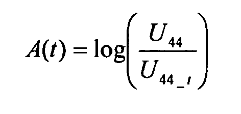
Neben der Kompensation von Temperaturschwankungen ermöglicht diese Vorgehensweise auch einen konstanten Messbereichs und ebenfalls eine gleich bleibende Signalqualität.In addition to the compensation of temperature fluctuations, this procedure also allows a constant measuring range and also a constant signal quality.
Während einer Therapie, also während einer einzigen Nierenersatzbehandlung, ist eine Alterung der Detektoren 44 und 45 zu vernachlässigen. Das Systems wird während der Nierenersatzbehandlung dann auf den Sollwert U45 am Detektor 45 geregelt, der unabhängig vom Dialysierflüssigkeitsfluss eine stabile und konstante emittierte elektromagnetische Strahlung ermöglicht. Damit kann der Temperaturdrift der Leuchtdiode 43 bzw. der Intensität I0 kompensiert werden. Der Stellwert der Regelung ist der elektrische Strom der Leuchtdiode 43, der proportional zur Intensität I0 der durch die Leuchtdiode 43 emittierten Strahlung ist. Eine reine Regelung auf den Detektor 44 durch einen Vorgabewert zu Beginn ist jedoch nicht sinnvoll, da Einflüsse während der Therapie nicht kompensiert werden können.During therapy, ie during a single renal replacement therapy, aging of the
Die Vorgabe des vordefinierten Sollwert im ersten Regelungsprozess dient zur Definition des Messbereichs der Elektronik und definiert gleichzeitig die Messauflösung der Absorption des Messsignals.The specification of the predefined setpoint value in the first control process serves to define the measuring range of the electronics and at the same time defines the measuring resolution of the absorption of the measuring signal.
In den Figuren nicht dargestellte Verstärkerschaltungen innerhalb der elektronischen Regelung 52 wandeln das Signal der Detektoren 44 und 45 in eine Messspannung um, für die Analog-Digital-Wandler mit einer Mikroprozessor-Messwertaufnahme zur Verfügung stehen. Diese Anpassung der Verstärkerschaltungen, welche nur vor jeder einzelnen Nierenersatzbehandlung erfolgen kann, könnte automatisch vor der Nierenersatzbehandlung parallel zu Regelung des Stroms der Leuchtdiode 43 erfolgen. Während der Behandlung ist allerdings nur eine Regelung des Stroms möglich.Amplifier circuits within the electronic controller 52, not shown in the figures, convert the signal from the
Mit Hilfe der Temperaturregelung wird für die Leuchtdiode 43 und die Detektoren 44 und 45 eine optimale Betriebstemperatur erreicht. Bei hohen Temperaturen muss der Strom als Stellgröße der Leuchtdiode 43 erhöht werden, um die emittierte elektromagnetische Strahlung bei steigenden Temperaturen bei einer konstanten Intensität zu halten. Umgekehrt muss bei sinkenden Temperaturen der Strom als Stellgröße der Leuchtdiode 43 gesenkt werden. Eine Erhöhung des Stroms ist jedoch nur im Betriebsbereich der Leuchtdiode 43 möglich und beschleunigt den Alterungsprozess. In einem Dialysegerät treten erfahrungsgemäß ernorme Temperaturschwankungen auf. Deshalb ist es sinnvoll Temperaturschwankungen durch eine Temperaturregelung 51 zu kompensieren, so dass die Vorrichtung in dem optimalen Temperaturbereich betrieben werden kann. Durch solche Maßnahmen wird auch der Alterungsprozess verlangsamt.With the aid of the temperature control, an optimum operating temperature is achieved for the light-emitting diode 43 and the
Ziel der Temperaturregelung ist, die Leuchtdiode 43 und die Detektoren 44 Σt 45 im optimalen Temperaturbereich zu betreiben bzw. schnell den optimalen Temperaturbereich für diese Komponenten zu erreichen, damit während der Therapie eine Änderung der Temperatur auf ein Minimum reduziert werden kann. Nach der Desinfektion kann es durch Erhitzung des Systems zu erhöhten Temperaturen an der Messeinrichtung 40 bzw. der Leuchtdiode 43 und/oder dem Detektorsystem 42 bzw. den Detektoren 44 und 45 kommen. Ferner hat beim Einschalten der Vorrichtung aus dem kalten Zustand die Eigenerwärmung des Systems eine Abkühlung zur Folge, wodurch zu Beginn eine sehr geringe Temperatur vorhanden ist. Daher ist es notwendig die Temperatur so schnell wie möglich in den Betriebsbereich der Komponenten zu bringen, während die Vorrichtung zur Nierenersatzbehandlung vorbereitet wird, um zu Beginn der Therapie bzw. während der Identifikation des System durch die oben beschriebene elektronische Regelung 52 bereits im Sollbereich der Temperatur zu sein. Damit ist es möglich auch sehr geringe Abweichungen der Detektoren 44 und 45 bezüglich eines Signaldrifts durch Temperaturänderungen auf ein Minimum zu reduzieren.The aim of the temperature control is to operate the light emitting diode 43 and the
Die Temperaturstabilisierung erfolgt mit einem Kühlkörper mit Wasserkühlung, der die Flusstemperatur der Dialysierflüssigkeit direkt mit dem Kühlkörper 43 der LED und/oder die Detektoren 44Σt45 koppelt. Die Wärmekapazität der Dialysierflüssigkeit ist deutlich höher als die des Kühlkörpers der Leuchtdiode 43 und definiert daher die Temperatur, was ohne zusätzlichen technischen Aufwand möglich ist. Damit ist es möglich die Temperatur näherungsweise konstant im Betriebsbereich der Komponenten zu halten und das System schnell in den optimalen Temperaturbereich zu bringen.The temperature stabilization is carried out with a cooling body with water cooling, which couples the flow temperature of the dialysis fluid directly to the heat sink 43 of the LED and / or the detectors 44Σt45. The heat capacity of the dialysis fluid is significantly higher than that of the heat sink of the light emitting diode 43 and therefore defines the temperature, which is possible without additional technical effort. This makes it possible to keep the temperature approximately constant in the operating range of the components and to bring the system quickly in the optimum temperature range.
Ohne enormen zusätzlichen Aufwand ist es jedoch nicht möglich die Temperatur so stabil zu halten, dass sie keinen weiteren Einfluss auf die Intensität der durch die Leuchtdiode 43 emittierte Strahlung hat. Daher muss parallel noch eine Stabilisierung der Leuchtintensität I0 mit der oben genannten elektronischen Regelung 52 erfolgen.However, without enormous additional effort, it is not possible to keep the temperature so stable that it has no further influence on the intensity of the light emitted by the light-emitting diode 43 has emitted radiation. Therefore, a stabilization of the luminous intensity I 0 must be carried out in parallel with the above-mentioned electronic control 52.
Eine Kühlung kann ebenfalls mit anderen aktiven und passiven Kühlmethoden durchgeführt werden. Als passive Kühlung kann die Leuchtdiode 43 bzw. die Detektoren 44 und 45 über das Gehäuse oder eine Wasserkühlung temperaturstabilisiert werden. Als aktive Kühlung ist der Einsatz eines Lüfters möglich, der die Temperatur abhängig von der Umgebungstemperatur regeln kann. Ebenso ist eine direkte Regelung mit einem Peltier-Element oder ähnlichen elektrothermischen Wandlern zurTemperaturstabilisierung möglich.Cooling can also be done with other active and passive cooling methods. As passive cooling, the light-emitting diode 43 or
- 1 --1 --
- Patientpatient
- 10 --10 -
- Dialysatordialyzer
- 11 --11 -
- Membranmembrane
- 12 --12 -
- Kammerchamber
- 13 --13 -
- Kammerchamber
- 14 --14 -
- Blutzuführleitungblood supply
- 15 --15 -
- Blutabführleitungblood discharge
- 20 --20 -
- ZulaufIntake
- 30 --30 -
- Ablaufprocedure
- 40 --40 -
- Messeinrichtungmeasuring device
- 41 --41 -
- Strahlungsquelleradiation source
- 42 --42 -
- Detektorsystemdetector system
- 43 --43 -
- Leuchtdiodeled
- 44 --44 -
- Detektordetector
- 45 --45 -
- Detektordetector
- 46 --46 -
- halbdurchlässiger Spiegelsemi-transparent mirror
- 50 --50 -
- Mittelmedium
- 51 --51 -
- Temperaturregelungtemperature control
- 52 --52 -
- elektronische Regelungelectronic regulation
- 53 --53 -
- Strahlengangbeam path
- 54 --54 -
- Teil der StrahlungPart of the radiation
- 55 --55 -
- verbrauchte Dialysierflüssigkeitused dialysis fluid
- 56 --56 -
- Teil der StrahlungPart of the radiation
- 57 --57 -
- Signalleitungsignal line
- 58 --58 -
- Signalleitungsignal line
- 59 --59 -
- Signalleitungsignal line
- 60 --60 -
- VentilValve
- 61 --61 -
- VentilValve
- 62 --62 -
- Bypassbypass
- 63 --63 -
- Pumpepump
Claims (15)
dadurch gekennzeichnet, dass
Mittel (50) vorgesehen sind, um auftretende Änderungen der Intensität der elektromagnetischen Strahlung der Strahlungsquelle (41) und/oder der Empfindlichkeit des Detektorsystems (42) zu kompensieren.Device for extracorporeal blood treatment with
characterized in that
Means (50) are provided to compensate for changes occurring in the intensity of the electromagnetic radiation of the radiation source (41) and / or the sensitivity of the detector system (42).
Priority Applications (12)
| Application Number | Priority Date | Filing Date | Title |
|---|---|---|---|
| PL09001890.4T PL2218472T5 (en) | 2009-02-11 | 2009-02-11 | Device for treating blood outside the body |
| ES09001890T ES2372563T5 (en) | 2009-02-11 | 2009-02-11 | Device for extracorporeal treatment of blood |
| DE202009017986U DE202009017986U1 (en) | 2009-02-11 | 2009-02-11 | Control and cooling of the UV sensor to compensate for a temperature dip to maintain the measuring range |
| AT09001890T ATE524205T1 (en) | 2009-02-11 | 2009-02-11 | DEVICE FOR EXTRACORPORATE BLOOD TREATMENT |
| EP09001890.4A EP2218472B2 (en) | 2009-02-11 | 2009-02-11 | Device for treating blood outside the body |
| RU2014133177/14A RU2594440C2 (en) | 2009-02-11 | 2010-02-05 | Device for extracorporeal blood purification and method of compensating for changes in intensity of electromagnetic radiation source in it |
| CN201080007333.7A CN102325555B (en) | 2009-02-11 | 2010-02-05 | The equipment of extracorporeal blood treatment |
| US13/148,371 US8834720B2 (en) | 2009-02-11 | 2010-02-05 | Apparatus for the extracorporeal treatment of blood |
| RU2011137416/14A RU2529692C2 (en) | 2009-02-11 | 2010-02-05 | Device for extracorporal blood purification |
| BRPI1008085A BRPI1008085B8 (en) | 2009-02-11 | 2010-02-05 | device for extracorporeal blood treatment |
| EP10704748A EP2396051A1 (en) | 2009-02-11 | 2010-02-05 | Apparatus for the extracorporeal treatment of blood |
| PCT/EP2010/000737 WO2010091826A1 (en) | 2009-02-11 | 2010-02-05 | Apparatus for the extracorporeal treatment of blood |
Applications Claiming Priority (1)
| Application Number | Priority Date | Filing Date | Title |
|---|---|---|---|
| EP09001890.4A EP2218472B2 (en) | 2009-02-11 | 2009-02-11 | Device for treating blood outside the body |
Publications (3)
| Publication Number | Publication Date |
|---|---|
| EP2218472A1 true EP2218472A1 (en) | 2010-08-18 |
| EP2218472B1 EP2218472B1 (en) | 2011-09-14 |
| EP2218472B2 EP2218472B2 (en) | 2022-03-16 |
Family
ID=40885966
Family Applications (2)
| Application Number | Title | Priority Date | Filing Date |
|---|---|---|---|
| EP09001890.4A Active EP2218472B2 (en) | 2009-02-11 | 2009-02-11 | Device for treating blood outside the body |
| EP10704748A Withdrawn EP2396051A1 (en) | 2009-02-11 | 2010-02-05 | Apparatus for the extracorporeal treatment of blood |
Family Applications After (1)
| Application Number | Title | Priority Date | Filing Date |
|---|---|---|---|
| EP10704748A Withdrawn EP2396051A1 (en) | 2009-02-11 | 2010-02-05 | Apparatus for the extracorporeal treatment of blood |
Country Status (10)
| Country | Link |
|---|---|
| US (1) | US8834720B2 (en) |
| EP (2) | EP2218472B2 (en) |
| CN (1) | CN102325555B (en) |
| AT (1) | ATE524205T1 (en) |
| BR (1) | BRPI1008085B8 (en) |
| DE (1) | DE202009017986U1 (en) |
| ES (1) | ES2372563T5 (en) |
| PL (1) | PL2218472T5 (en) |
| RU (2) | RU2529692C2 (en) |
| WO (1) | WO2010091826A1 (en) |
Cited By (5)
| Publication number | Priority date | Publication date | Assignee | Title |
|---|---|---|---|---|
| WO2012062257A1 (en) * | 2010-09-29 | 2012-05-18 | B. Braun Avitum Ag | Dialysate profiling controlled by uv monitoring |
| EP2790008A4 (en) * | 2011-12-05 | 2016-01-06 | Rion Co | Biological particle counter, biological particle counting method, dialysate monitoring system, and water purification monitoring system |
| CN106289522A (en) * | 2016-07-28 | 2017-01-04 | 田雨庭 | A kind of monochromator of Mixed design |
| EP2514447B1 (en) | 2009-12-14 | 2020-08-05 | Nikkiso Company Limited | Blood purification device |
| EP2514448B1 (en) | 2009-12-14 | 2021-03-10 | Nikkiso Company Limited | Blood purification apparatus |
Families Citing this family (31)
| Publication number | Priority date | Publication date | Assignee | Title |
|---|---|---|---|---|
| US8535522B2 (en) | 2009-02-12 | 2013-09-17 | Fresenius Medical Care Holdings, Inc. | System and method for detection of disconnection in an extracorporeal blood circuit |
| US9358331B2 (en) | 2007-09-13 | 2016-06-07 | Fresenius Medical Care Holdings, Inc. | Portable dialysis machine with improved reservoir heating system |
| US8105487B2 (en) | 2007-09-25 | 2012-01-31 | Fresenius Medical Care Holdings, Inc. | Manifolds for use in conducting dialysis |
| US8240636B2 (en) | 2009-01-12 | 2012-08-14 | Fresenius Medical Care Holdings, Inc. | Valve system |
| US9308307B2 (en) | 2007-09-13 | 2016-04-12 | Fresenius Medical Care Holdings, Inc. | Manifold diaphragms |
| US9199022B2 (en) | 2008-09-12 | 2015-12-01 | Fresenius Medical Care Holdings, Inc. | Modular reservoir assembly for a hemodialysis and hemofiltration system |
| US8597505B2 (en) | 2007-09-13 | 2013-12-03 | Fresenius Medical Care Holdings, Inc. | Portable dialysis machine |
| CA2706919C (en) | 2007-11-29 | 2018-03-06 | Fresenius Medical Care Holdings, Inc. | System and method for conducting hemodialysis and hemofiltration |
| WO2010042666A2 (en) | 2008-10-07 | 2010-04-15 | Xcorporeal, Inc. | Priming system and method for dialysis systems |
| WO2010042667A2 (en) | 2008-10-07 | 2010-04-15 | Xcorporeal, Inc. | Thermal flow meter |
| CN105056324B (en) | 2008-10-30 | 2019-01-01 | 弗雷塞尼斯医疗保健控股公司 | Modular portable dialysis system |
| AT510631B1 (en) * | 2010-10-20 | 2013-01-15 | Scan Messtechnik Ges M B H | SPECTROMETER |
| US9861733B2 (en) | 2012-03-23 | 2018-01-09 | Nxstage Medical Inc. | Peritoneal dialysis systems, devices, and methods |
| CA2830085A1 (en) | 2011-03-23 | 2012-09-27 | Nxstage Medical, Inc. | Peritoneal dialysis systems, devices, and methods |
| EP2510958B2 (en) * | 2011-04-11 | 2023-02-15 | Fresenius Medical Care Deutschland GmbH | Method and apparatus for monitoring a treatment of a patient, preferably for monitoring hemodialysis, hemodiafiltration and/or peritoneal dialysis |
| JP5965151B2 (en) * | 2012-01-16 | 2016-08-03 | リオン株式会社 | Bioparticle counter for dialysis, bioparticle counting method for dialysis, and dialysate monitoring system |
| EP2674103A1 (en) | 2012-06-15 | 2013-12-18 | Fresenius Medical Care Deutschland GmbH | Method and device for monitoring an extracorporeal blood treatment of a patient |
| WO2014018798A2 (en) | 2012-07-25 | 2014-01-30 | Nxstage Medical, Inc. | Fluid property measurement devices, methods, and systems |
| US9846085B2 (en) | 2012-07-25 | 2017-12-19 | Nxstage Medical, Inc. | Fluid property measurement devices, methods, and systems |
| US9201036B2 (en) | 2012-12-21 | 2015-12-01 | Fresenius Medical Care Holdings, Inc. | Method and system of monitoring electrolyte levels and composition using capacitance or induction |
| US9157786B2 (en) | 2012-12-24 | 2015-10-13 | Fresenius Medical Care Holdings, Inc. | Load suspension and weighing system for a dialysis machine reservoir |
| ES2717698T3 (en) * | 2013-05-17 | 2019-06-24 | Fresenius Medical Care Deutschland Gmbh | Device and procedure for the optimization of energy consumption in a medical device |
| US9354640B2 (en) | 2013-11-11 | 2016-05-31 | Fresenius Medical Care Holdings, Inc. | Smart actuator for valve |
| PL2995329T3 (en) | 2014-09-15 | 2017-07-31 | Gambro Lundia Ab | Apparatus for extracorporeal treatment of blood and method of control of a blood-warming device in an extracorporeal blood treatment apparatus |
| US11826545B2 (en) | 2016-09-08 | 2023-11-28 | Fresenius Medical Care Holdings, Inc. | Optical blood detection system |
| DE102016119259A1 (en) * | 2016-10-10 | 2018-04-12 | B. Braun Avitum Ag | Apparatus and method for recirculation measurement |
| DE102017003508A1 (en) * | 2017-04-11 | 2018-10-11 | Fresenius Medical Care Deutschland Gmbh | Apparatus for extracorporeal blood treatment and method for operating an extracorporeal blood treatment apparatus |
| GB201720405D0 (en) * | 2017-12-07 | 2018-01-24 | Biosafe Sa | A bioprocessing system |
| US11207454B2 (en) | 2018-02-28 | 2021-12-28 | Nxstage Medical, Inc. | Fluid preparation and treatment devices methods and systems |
| DE102019203318A1 (en) * | 2019-03-12 | 2020-09-17 | Robert Bosch Gmbh | Thermal regulation of a sensor device |
| DE102021113519A1 (en) * | 2021-05-26 | 2022-12-01 | B.Braun Avitum Ag | Optical sensor for determining a dialysis dose |
Citations (4)
| Publication number | Priority date | Publication date | Assignee | Title |
|---|---|---|---|---|
| WO1999023479A1 (en) * | 1997-10-31 | 1999-05-14 | Technical Chemicals & Products, Inc. | Reflectometer |
| WO1999062574A1 (en) * | 1998-06-04 | 1999-12-09 | Althin Medical Ab | Method for determining waste products in the dialysis liquid in dialysis treatment |
| DE102005063263A1 (en) * | 2005-12-30 | 2007-07-05 | Opsolution Mobile Gmbh | Measurement result generating method for use in e.g. transmissive spectroscopic application, involves processing compensation function representing dependency of distribution of lights by temperature of diode, within signal processing |
| EP2005982A1 (en) | 2007-06-20 | 2008-12-24 | B. Braun Avitum AG | Method for determining the reduction ratio or the Kt/V value of a kidney substitution treatment and apparatus for the realisation of the method |
Family Cites Families (18)
| Publication number | Priority date | Publication date | Assignee | Title |
|---|---|---|---|---|
| SE415397B (en) | 1978-06-02 | 1980-09-29 | Asea Ab | FIBEROPTICAL METDON |
| SE424022B (en) | 1980-10-21 | 1982-06-21 | Asea Ab | FIBER OPTICAL METDON FOR SPECTRAL ANALYSIS |
| DE4128458C2 (en) * | 1991-08-28 | 1994-02-10 | Siemens Ag | Method and device for determining the concentration of a component, in particular glucose, a liquid optically active substance, in particular the body fluid of a patient, by polarimetry |
| DE4235768A1 (en) * | 1992-10-24 | 1994-05-19 | Cho Ok Kyung | Modified semiconductor laser diode with integrated temperature control part |
| US5591344A (en) * | 1995-02-13 | 1997-01-07 | Aksys, Ltd. | Hot water disinfection of dialysis machines, including the extracorporeal circuit thereof |
| US5825399A (en) | 1996-02-28 | 1998-10-20 | Eastman Kodak Company | Data-dependent thermal compensation for an LED printhead |
| US6027256A (en) * | 1997-02-07 | 2000-02-22 | Coherent, Inc. | Composite laser diode enclosure and method for making the same |
| US6087182A (en) * | 1998-08-27 | 2000-07-11 | Abbott Laboratories | Reagentless analysis of biological samples |
| DE10051943B4 (en) * | 2000-10-19 | 2015-01-15 | Fresenius Medical Care Deutschland Gmbh | Method and device for pulse wave transit time determination and extracorporeal blood treatment device with such a device |
| US7002670B2 (en) * | 2002-06-12 | 2006-02-21 | Baxter International Inc. | Optical sensor and method for measuring concentration of a chemical constituent using its intrinsic optical absorbance |
| US20040000012A1 (en) | 2002-06-26 | 2004-01-01 | Borregaard Chemcell | Treatment of a mixture containing cellulose |
| US7326576B2 (en) * | 2003-04-09 | 2008-02-05 | Prescient Medical, Inc. | Raman spectroscopic monitoring of hemodialysis |
| EP1663346A1 (en) * | 2003-09-23 | 2006-06-07 | Gambro Lundia AB | An apparatus, a system and a method relating to hemodialysis, hemodiafiltration, hemofiltration or peritoneal dialysis |
| JP2006178349A (en) | 2004-12-24 | 2006-07-06 | Sanyo Electric Co Ltd | Rear projection video display device |
| RU2306955C2 (en) * | 2005-05-26 | 2007-09-27 | Государственное учреждение Российский научный центр хирургии РАМН (РНЦХ РАМН) | Method and device for biohemofiltration |
| DE102006029899B4 (en) * | 2006-06-29 | 2009-06-04 | Fresenius Medical Care Deutschland Gmbh | Spectroscopic detector and method for the determination of blood and biological markers in liquids |
| WO2008144577A1 (en) | 2007-05-18 | 2008-11-27 | Optiscan Biomedical Corporation | Fluid mixing systems and methods |
| SG10201800720YA (en) * | 2011-05-24 | 2018-03-28 | Deka Products Lp | Blood treatment systems and methods |
-
2009
- 2009-02-11 EP EP09001890.4A patent/EP2218472B2/en active Active
- 2009-02-11 ES ES09001890T patent/ES2372563T5/en active Active
- 2009-02-11 AT AT09001890T patent/ATE524205T1/en active
- 2009-02-11 PL PL09001890.4T patent/PL2218472T5/en unknown
- 2009-02-11 DE DE202009017986U patent/DE202009017986U1/en not_active Expired - Lifetime
-
2010
- 2010-02-05 EP EP10704748A patent/EP2396051A1/en not_active Withdrawn
- 2010-02-05 US US13/148,371 patent/US8834720B2/en active Active
- 2010-02-05 RU RU2011137416/14A patent/RU2529692C2/en active
- 2010-02-05 RU RU2014133177/14A patent/RU2594440C2/en active
- 2010-02-05 BR BRPI1008085A patent/BRPI1008085B8/en active IP Right Grant
- 2010-02-05 WO PCT/EP2010/000737 patent/WO2010091826A1/en active Application Filing
- 2010-02-05 CN CN201080007333.7A patent/CN102325555B/en active Active
Patent Citations (5)
| Publication number | Priority date | Publication date | Assignee | Title |
|---|---|---|---|---|
| WO1999023479A1 (en) * | 1997-10-31 | 1999-05-14 | Technical Chemicals & Products, Inc. | Reflectometer |
| WO1999062574A1 (en) * | 1998-06-04 | 1999-12-09 | Althin Medical Ab | Method for determining waste products in the dialysis liquid in dialysis treatment |
| EP1083948A1 (en) | 1998-06-04 | 2001-03-21 | Althin Medical Ab | Method for determining waste products in the dialysis liquid in dialysis treatment |
| DE102005063263A1 (en) * | 2005-12-30 | 2007-07-05 | Opsolution Mobile Gmbh | Measurement result generating method for use in e.g. transmissive spectroscopic application, involves processing compensation function representing dependency of distribution of lights by temperature of diode, within signal processing |
| EP2005982A1 (en) | 2007-06-20 | 2008-12-24 | B. Braun Avitum AG | Method for determining the reduction ratio or the Kt/V value of a kidney substitution treatment and apparatus for the realisation of the method |
Non-Patent Citations (1)
| Title |
|---|
| FRIDOLIN I ET AL: "ON-LINE MONITORING OF SOLUTES IN DIALYSATE USING ABSORPTION OF ULTRAVIOLET RADIATION: TECHNIQUE DESCRIPTION", INTERNATIONAL JOURNAL OF ARTIFICIAL ORGANS, MILAN, IT, vol. 25, no. 8, 1 August 2002 (2002-08-01), pages 748 - 761, XP008101248, ISSN: 0391-3988 * |
Cited By (10)
| Publication number | Priority date | Publication date | Assignee | Title |
|---|---|---|---|---|
| EP2514447B1 (en) | 2009-12-14 | 2020-08-05 | Nikkiso Company Limited | Blood purification device |
| EP2514448B1 (en) | 2009-12-14 | 2021-03-10 | Nikkiso Company Limited | Blood purification apparatus |
| WO2012062257A1 (en) * | 2010-09-29 | 2012-05-18 | B. Braun Avitum Ag | Dialysate profiling controlled by uv monitoring |
| CN103140248A (en) * | 2010-09-29 | 2013-06-05 | 贝朗爱敦股份公司 | Dialysate profiling controlled by uv monitoring |
| RU2551309C2 (en) * | 2010-09-29 | 2015-05-20 | Б. Браун Авитум Аг | Analysis of dialysate profile, controlled by uv-monitoring |
| CN103140248B (en) * | 2010-09-29 | 2016-05-04 | 贝朗爱敦股份公司 | By ultraviolet inspection control dislysate tendency |
| EP2790008A4 (en) * | 2011-12-05 | 2016-01-06 | Rion Co | Biological particle counter, biological particle counting method, dialysate monitoring system, and water purification monitoring system |
| US9267845B2 (en) | 2011-12-05 | 2016-02-23 | Rion Co., Ltd. | Apparatus for counting viable particles in liquid in real time, dialysis fluid monitoring system and purified water monitoring system using the apparatus, and method of counting viable particles in liquid in real time |
| EP3211402A1 (en) * | 2011-12-05 | 2017-08-30 | Rion Co., Ltd. | Viable particle counter and dialysis fluid monitoring system |
| CN106289522A (en) * | 2016-07-28 | 2017-01-04 | 田雨庭 | A kind of monochromator of Mixed design |
Also Published As
| Publication number | Publication date |
|---|---|
| ES2372563T3 (en) | 2012-01-23 |
| BRPI1008085B1 (en) | 2020-09-15 |
| ES2372563T5 (en) | 2022-06-14 |
| CN102325555B (en) | 2015-10-21 |
| RU2011137416A (en) | 2013-03-20 |
| PL2218472T3 (en) | 2012-04-30 |
| EP2396051A1 (en) | 2011-12-21 |
| WO2010091826A1 (en) | 2010-08-19 |
| DE202009017986U1 (en) | 2010-10-07 |
| BRPI1008085A2 (en) | 2016-03-15 |
| EP2218472B1 (en) | 2011-09-14 |
| RU2529692C2 (en) | 2014-09-27 |
| PL2218472T5 (en) | 2023-03-13 |
| US8834720B2 (en) | 2014-09-16 |
| RU2594440C2 (en) | 2016-08-20 |
| BRPI1008085B8 (en) | 2021-06-22 |
| CN102325555A (en) | 2012-01-18 |
| RU2014133177A (en) | 2016-02-27 |
| US20110309019A1 (en) | 2011-12-22 |
| EP2218472B2 (en) | 2022-03-16 |
| ATE524205T1 (en) | 2011-09-15 |
Similar Documents
| Publication | Publication Date | Title |
|---|---|---|
| EP2218472B1 (en) | Device for treating blood outside the body | |
| EP2605810B1 (en) | Apparatus for extracorporeal blood treatment | |
| EP2413991B1 (en) | Device for determining and controlling the concentration of at least one solute in a fluid circuit | |
| EP1835950B1 (en) | Device and method for detecting complications during an extracorporeal blood treatment | |
| DE69732442T2 (en) | Continuous closed loop decontamination system and method | |
| DE60206254T2 (en) | MONITORING AND CONTROL OF HYDROGEN PEROXIDE VAPOR PROCESSING TECHNIQUES THROUGH THE USE OF MEDIUM INFRARED SPECTROSCOPY | |
| EP2799097B1 (en) | Device for treating blood outside the body | |
| EP3431118B1 (en) | Device for providing isonatraemic dialysis | |
| EP2579910B1 (en) | Apparatus for extracorporeal blood treatment, comprising a measuring device for determining the luminescence of the spent dialysate | |
| EP2783715B1 (en) | Method for detecting recirculation in an arteriovenous shunt during ongoing haemodialysis and dialysis system | |
| EP2985045B1 (en) | Method for adjusting a blood flow in a dialysis device and dialysis device | |
| EP2416699B1 (en) | Device and method for measuring a blood constituent in blood for an extracorporeal blood treatment device | |
| EP0175352A2 (en) | Method and device for rapidly ascertaining the parameters of a sample medium | |
| WO2013079169A1 (en) | Method and device for determining a blood component | |
| DE2443435A1 (en) | BLOOD LEVEL DETECTOR | |
| EP2783716B1 (en) | Method and device for detecting recirculation in a shunt | |
| EP3955988B1 (en) | Recirculation measurement by means of diffusion equilibrium | |
| EP2767821A1 (en) | Photometric measuring device and method for measuring an optical absorbency of a fluid with a variable concentration of at least one light absorbent substance, and blood processing device with such a measuring device | |
| EP3141896B1 (en) | Method and system for operating a device for treating an aqueous fluid | |
| EP4132604B1 (en) | Optical sensor for determining a dialysis dose | |
| EP2746771B1 (en) | Device for determining waste products such as indoxyl sulphates in dialysis | |
| DE102009040104A1 (en) | Device for extracorporeal blood treatment | |
| EP3400977B1 (en) | Online linearization of an optical sensor | |
| EP0440208A1 (en) | Method and apparatus for improved continuous separation of sour milk into whey and curd |
Legal Events
| Date | Code | Title | Description |
|---|---|---|---|
| PUAI | Public reference made under article 153(3) epc to a published international application that has entered the european phase |
Free format text: ORIGINAL CODE: 0009012 |
|
| AK | Designated contracting states |
Kind code of ref document: A1 Designated state(s): AT BE BG CH CY CZ DE DK EE ES FI FR GB GR HR HU IE IS IT LI LT LU LV MC MK MT NL NO PL PT RO SE SI SK TR |
|
| AX | Request for extension of the european patent |
Extension state: AL BA RS |
|
| 17P | Request for examination filed |
Effective date: 20110210 |
|
| AKX | Designation fees paid |
Designated state(s): AT BE BG CH CY CZ DE DK EE ES FI FR GB GR HR HU IE IS IT LI LT LU LV MC MK MT NL NO PL PT RO SE SI SK TR |
|
| GRAP | Despatch of communication of intention to grant a patent |
Free format text: ORIGINAL CODE: EPIDOSNIGR1 |
|
| RIC1 | Information provided on ipc code assigned before grant |
Ipc: G01N 21/33 20060101ALI20110513BHEP Ipc: A61M 1/16 20060101AFI20110513BHEP Ipc: G01J 3/42 20060101ALI20110513BHEP |
|
| GRAS | Grant fee paid |
Free format text: ORIGINAL CODE: EPIDOSNIGR3 |
|
| GRAA | (expected) grant |
Free format text: ORIGINAL CODE: 0009210 |
|
| STAA | Information on the status of an ep patent application or granted ep patent |
Free format text: STATUS: THE PATENT HAS BEEN GRANTED |
|
| AK | Designated contracting states |
Kind code of ref document: B1 Designated state(s): AT BE BG CH CY CZ DE DK EE ES FI FR GB GR HR HU IE IS IT LI LT LU LV MC MK MT NL NO PL PT RO SE SI SK TR |
|
| REG | Reference to a national code |
Ref country code: GB Ref legal event code: FG4D Free format text: NOT ENGLISH |
|
| REG | Reference to a national code |
Ref country code: CH Ref legal event code: EP |
|
| REG | Reference to a national code |
Ref country code: IE Ref legal event code: FG4D Free format text: LANGUAGE OF EP DOCUMENT: GERMAN |
|
| REG | Reference to a national code |
Ref country code: DE Ref legal event code: R096 Ref document number: 502009001344 Country of ref document: DE Effective date: 20111201 |
|
| REG | Reference to a national code |
Ref country code: CH Ref legal event code: PFA Owner name: B. BRAUN AVITUM AG Free format text: B. BRAUN AVITUM AG#PL-LA-DE08P SCHWARZENBERGER WEG 73-79#34212 MELSUNGEN (DE) -TRANSFER TO- B. BRAUN AVITUM AG#AM BUSCHBERG 1#34212 MELSUNGEN (DE) |
|
| REG | Reference to a national code |
Ref country code: SE Ref legal event code: TRGR |
|
| REG | Reference to a national code |
Ref country code: NL Ref legal event code: VDEP Effective date: 20110914 |
|
| REG | Reference to a national code |
Ref country code: ES Ref legal event code: FG2A Ref document number: 2372563 Country of ref document: ES Kind code of ref document: T3 Effective date: 20120123 |
|
| PG25 | Lapsed in a contracting state [announced via postgrant information from national office to epo] |
Ref country code: NO Free format text: LAPSE BECAUSE OF FAILURE TO SUBMIT A TRANSLATION OF THE DESCRIPTION OR TO PAY THE FEE WITHIN THE PRESCRIBED TIME-LIMIT Effective date: 20111214 Ref country code: HR Free format text: LAPSE BECAUSE OF FAILURE TO SUBMIT A TRANSLATION OF THE DESCRIPTION OR TO PAY THE FEE WITHIN THE PRESCRIBED TIME-LIMIT Effective date: 20110914 Ref country code: LT Free format text: LAPSE BECAUSE OF FAILURE TO SUBMIT A TRANSLATION OF THE DESCRIPTION OR TO PAY THE FEE WITHIN THE PRESCRIBED TIME-LIMIT Effective date: 20110914 Ref country code: FI Free format text: LAPSE BECAUSE OF FAILURE TO SUBMIT A TRANSLATION OF THE DESCRIPTION OR TO PAY THE FEE WITHIN THE PRESCRIBED TIME-LIMIT Effective date: 20110914 |
|
| LTIE | Lt: invalidation of european patent or patent extension |
Effective date: 20110914 |
|
| PG25 | Lapsed in a contracting state [announced via postgrant information from national office to epo] |
Ref country code: LV Free format text: LAPSE BECAUSE OF FAILURE TO SUBMIT A TRANSLATION OF THE DESCRIPTION OR TO PAY THE FEE WITHIN THE PRESCRIBED TIME-LIMIT Effective date: 20110914 Ref country code: GR Free format text: LAPSE BECAUSE OF FAILURE TO SUBMIT A TRANSLATION OF THE DESCRIPTION OR TO PAY THE FEE WITHIN THE PRESCRIBED TIME-LIMIT Effective date: 20111215 Ref country code: SI Free format text: LAPSE BECAUSE OF FAILURE TO SUBMIT A TRANSLATION OF THE DESCRIPTION OR TO PAY THE FEE WITHIN THE PRESCRIBED TIME-LIMIT Effective date: 20110914 Ref country code: CY Free format text: LAPSE BECAUSE OF FAILURE TO SUBMIT A TRANSLATION OF THE DESCRIPTION OR TO PAY THE FEE WITHIN THE PRESCRIBED TIME-LIMIT Effective date: 20110914 |
|
| REG | Reference to a national code |
Ref country code: IE Ref legal event code: FD4D |
|
| PG25 | Lapsed in a contracting state [announced via postgrant information from national office to epo] |
Ref country code: IE Free format text: LAPSE BECAUSE OF FAILURE TO SUBMIT A TRANSLATION OF THE DESCRIPTION OR TO PAY THE FEE WITHIN THE PRESCRIBED TIME-LIMIT Effective date: 20110914 Ref country code: SK Free format text: LAPSE BECAUSE OF FAILURE TO SUBMIT A TRANSLATION OF THE DESCRIPTION OR TO PAY THE FEE WITHIN THE PRESCRIBED TIME-LIMIT Effective date: 20110914 Ref country code: CZ Free format text: LAPSE BECAUSE OF FAILURE TO SUBMIT A TRANSLATION OF THE DESCRIPTION OR TO PAY THE FEE WITHIN THE PRESCRIBED TIME-LIMIT Effective date: 20110914 Ref country code: IS Free format text: LAPSE BECAUSE OF FAILURE TO SUBMIT A TRANSLATION OF THE DESCRIPTION OR TO PAY THE FEE WITHIN THE PRESCRIBED TIME-LIMIT Effective date: 20120114 |
|
| REG | Reference to a national code |
Ref country code: PL Ref legal event code: T3 |
|
| PG25 | Lapsed in a contracting state [announced via postgrant information from national office to epo] |
Ref country code: EE Free format text: LAPSE BECAUSE OF FAILURE TO SUBMIT A TRANSLATION OF THE DESCRIPTION OR TO PAY THE FEE WITHIN THE PRESCRIBED TIME-LIMIT Effective date: 20110914 Ref country code: NL Free format text: LAPSE BECAUSE OF FAILURE TO SUBMIT A TRANSLATION OF THE DESCRIPTION OR TO PAY THE FEE WITHIN THE PRESCRIBED TIME-LIMIT Effective date: 20110914 Ref country code: PT Free format text: LAPSE BECAUSE OF FAILURE TO SUBMIT A TRANSLATION OF THE DESCRIPTION OR TO PAY THE FEE WITHIN THE PRESCRIBED TIME-LIMIT Effective date: 20120116 Ref country code: RO Free format text: LAPSE BECAUSE OF FAILURE TO SUBMIT A TRANSLATION OF THE DESCRIPTION OR TO PAY THE FEE WITHIN THE PRESCRIBED TIME-LIMIT Effective date: 20110914 |
|
| PLBI | Opposition filed |
Free format text: ORIGINAL CODE: 0009260 |
|
| 26 | Opposition filed |
Opponent name: FRESENIUS MEDICAL CARE DEUTSCHLAND GMBH Effective date: 20120612 |
|
| PLAX | Notice of opposition and request to file observation + time limit sent |
Free format text: ORIGINAL CODE: EPIDOSNOBS2 |
|
| PG25 | Lapsed in a contracting state [announced via postgrant information from national office to epo] |
Ref country code: DK Free format text: LAPSE BECAUSE OF FAILURE TO SUBMIT A TRANSLATION OF THE DESCRIPTION OR TO PAY THE FEE WITHIN THE PRESCRIBED TIME-LIMIT Effective date: 20110914 |
|
| BERE | Be: lapsed |
Owner name: B. BRAUN AVITUM A.G. Effective date: 20120228 |
|
| REG | Reference to a national code |
Ref country code: DE Ref legal event code: R026 Ref document number: 502009001344 Country of ref document: DE Effective date: 20120612 |
|
| PG25 | Lapsed in a contracting state [announced via postgrant information from national office to epo] |
Ref country code: MC Free format text: LAPSE BECAUSE OF NON-PAYMENT OF DUE FEES Effective date: 20120229 |
|
| PLBB | Reply of patent proprietor to notice(s) of opposition received |
Free format text: ORIGINAL CODE: EPIDOSNOBS3 |
|
| PG25 | Lapsed in a contracting state [announced via postgrant information from national office to epo] |
Ref country code: BE Free format text: LAPSE BECAUSE OF NON-PAYMENT OF DUE FEES Effective date: 20120228 |
|
| PG25 | Lapsed in a contracting state [announced via postgrant information from national office to epo] |
Ref country code: MK Free format text: LAPSE BECAUSE OF FAILURE TO SUBMIT A TRANSLATION OF THE DESCRIPTION OR TO PAY THE FEE WITHIN THE PRESCRIBED TIME-LIMIT Effective date: 20110914 |
|
| PG25 | Lapsed in a contracting state [announced via postgrant information from national office to epo] |
Ref country code: BG Free format text: LAPSE BECAUSE OF FAILURE TO SUBMIT A TRANSLATION OF THE DESCRIPTION OR TO PAY THE FEE WITHIN THE PRESCRIBED TIME-LIMIT Effective date: 20111214 |
|
| PG25 | Lapsed in a contracting state [announced via postgrant information from national office to epo] |
Ref country code: MT Free format text: LAPSE BECAUSE OF FAILURE TO SUBMIT A TRANSLATION OF THE DESCRIPTION OR TO PAY THE FEE WITHIN THE PRESCRIBED TIME-LIMIT Effective date: 20110914 |
|
| PG25 | Lapsed in a contracting state [announced via postgrant information from national office to epo] |
Ref country code: TR Free format text: LAPSE BECAUSE OF FAILURE TO SUBMIT A TRANSLATION OF THE DESCRIPTION OR TO PAY THE FEE WITHIN THE PRESCRIBED TIME-LIMIT Effective date: 20110914 |
|
| PG25 | Lapsed in a contracting state [announced via postgrant information from national office to epo] |
Ref country code: LU Free format text: LAPSE BECAUSE OF NON-PAYMENT OF DUE FEES Effective date: 20120211 |
|
| PG25 | Lapsed in a contracting state [announced via postgrant information from national office to epo] |
Ref country code: HU Free format text: LAPSE BECAUSE OF FAILURE TO SUBMIT A TRANSLATION OF THE DESCRIPTION OR TO PAY THE FEE WITHIN THE PRESCRIBED TIME-LIMIT Effective date: 20090211 |
|
| REG | Reference to a national code |
Ref country code: DE Ref legal event code: R082 Ref document number: 502009001344 Country of ref document: DE Representative=s name: WINTER, BRANDL, FUERNISS, HUEBNER, ROESS, KAIS, DE Ref country code: DE Ref legal event code: R082 Ref document number: 502009001344 Country of ref document: DE |
|
| REG | Reference to a national code |
Ref country code: AT Ref legal event code: MM01 Ref document number: 524205 Country of ref document: AT Kind code of ref document: T Effective date: 20140211 |
|
| PG25 | Lapsed in a contracting state [announced via postgrant information from national office to epo] |
Ref country code: AT Free format text: LAPSE BECAUSE OF NON-PAYMENT OF DUE FEES Effective date: 20140211 |
|
| REG | Reference to a national code |
Ref country code: FR Ref legal event code: PLFP Year of fee payment: 8 |
|
| PLCK | Communication despatched that opposition was rejected |
Free format text: ORIGINAL CODE: EPIDOSNREJ1 |
|
| APBM | Appeal reference recorded |
Free format text: ORIGINAL CODE: EPIDOSNREFNO |
|
| APBP | Date of receipt of notice of appeal recorded |
Free format text: ORIGINAL CODE: EPIDOSNNOA2O |
|
| APAH | Appeal reference modified |
Free format text: ORIGINAL CODE: EPIDOSCREFNO |
|
| PLAB | Opposition data, opponent's data or that of the opponent's representative modified |
Free format text: ORIGINAL CODE: 0009299OPPO |
|
| APBQ | Date of receipt of statement of grounds of appeal recorded |
Free format text: ORIGINAL CODE: EPIDOSNNOA3O |
|
| R26 | Opposition filed (corrected) |
Opponent name: FRESENIUS MEDICAL CARE DEUTSCHLAND GMBH Effective date: 20120612 |
|
| REG | Reference to a national code |
Ref country code: FR Ref legal event code: PLFP Year of fee payment: 9 |
|
| REG | Reference to a national code |
Ref country code: FR Ref legal event code: PLFP Year of fee payment: 10 |
|
| PLAB | Opposition data, opponent's data or that of the opponent's representative modified |
Free format text: ORIGINAL CODE: 0009299OPPO |
|
| R26 | Opposition filed (corrected) |
Opponent name: FRESENIUS MEDICAL CARE DEUTSCHLAND GMBH Effective date: 20120612 |
|
| APBU | Appeal procedure closed |
Free format text: ORIGINAL CODE: EPIDOSNNOA9O |
|
| PUAH | Patent maintained in amended form |
Free format text: ORIGINAL CODE: 0009272 |
|
| STAA | Information on the status of an ep patent application or granted ep patent |
Free format text: STATUS: PATENT MAINTAINED AS AMENDED |
|
| 27A | Patent maintained in amended form |
Effective date: 20220316 |
|
| AK | Designated contracting states |
Kind code of ref document: B2 Designated state(s): AT BE BG CH CY CZ DE DK EE ES FI FR GB GR HR HU IE IS IT LI LT LU LV MC MK MT NL NO PL PT RO SE SI SK TR |
|
| REG | Reference to a national code |
Ref country code: DE Ref legal event code: R102 Ref document number: 502009001344 Country of ref document: DE |
|
| REG | Reference to a national code |
Ref country code: ES Ref legal event code: DC2A Ref document number: 2372563 Country of ref document: ES Kind code of ref document: T5 Effective date: 20220614 |
|
| REG | Reference to a national code |
Ref country code: SE Ref legal event code: RPEO |
|
| P01 | Opt-out of the competence of the unified patent court (upc) registered |
Effective date: 20230929 |
|
| PGFP | Annual fee paid to national office [announced via postgrant information from national office to epo] |
Ref country code: ES Payment date: 20240319 Year of fee payment: 16 |
|
| PGFP | Annual fee paid to national office [announced via postgrant information from national office to epo] |
Ref country code: DE Payment date: 20240216 Year of fee payment: 16 Ref country code: GB Payment date: 20240222 Year of fee payment: 16 Ref country code: CH Payment date: 20240301 Year of fee payment: 16 |
|
| PGFP | Annual fee paid to national office [announced via postgrant information from national office to epo] |
Ref country code: SE Payment date: 20240221 Year of fee payment: 16 Ref country code: PL Payment date: 20240131 Year of fee payment: 16 Ref country code: IT Payment date: 20240229 Year of fee payment: 16 Ref country code: FR Payment date: 20240221 Year of fee payment: 16 |