EP2218302B1 - Bonden von thermoplasten - Google Patents
Bonden von thermoplasten Download PDFInfo
- Publication number
- EP2218302B1 EP2218302B1 EP08840048A EP08840048A EP2218302B1 EP 2218302 B1 EP2218302 B1 EP 2218302B1 EP 08840048 A EP08840048 A EP 08840048A EP 08840048 A EP08840048 A EP 08840048A EP 2218302 B1 EP2218302 B1 EP 2218302B1
- Authority
- EP
- European Patent Office
- Prior art keywords
- layer
- thermoplastic
- leading edge
- heater
- thermoplastic layer
- Prior art date
- Legal status (The legal status is an assumption and is not a legal conclusion. Google has not performed a legal analysis and makes no representation as to the accuracy of the status listed.)
- Active
Links
Images

Classifications
-
- H—ELECTRICITY
- H05—ELECTRIC TECHNIQUES NOT OTHERWISE PROVIDED FOR
- H05B—ELECTRIC HEATING; ELECTRIC LIGHT SOURCES NOT OTHERWISE PROVIDED FOR; CIRCUIT ARRANGEMENTS FOR ELECTRIC LIGHT SOURCES, IN GENERAL
- H05B3/00—Ohmic-resistance heating
- H05B3/20—Heating elements having extended surface area substantially in a two-dimensional [2D] plane, e.g. plate-heater
- H05B3/34—Heating elements having extended surface area substantially in a two-dimensional [2D] plane, e.g. plate-heater flexible, e.g. heating nets or webs
- H05B3/36—Heating elements having extended surface area substantially in a two-dimensional [2D] plane, e.g. plate-heater flexible, e.g. heating nets or webs heating conductor embedded in insulating material
-
- B—PERFORMING OPERATIONS; TRANSPORTING
- B64—AIRCRAFT; AVIATION; COSMONAUTICS
- B64D—EQUIPMENT FOR FITTING IN OR TO AIRCRAFT; FLIGHT SUITS; PARACHUTES; ARRANGEMENT OR MOUNTING OF POWER PLANTS OR PROPULSION TRANSMISSIONS IN AIRCRAFT
- B64D15/00—De-icing or preventing icing on exterior surfaces of aircraft
- B64D15/12—De-icing or preventing icing on exterior surfaces of aircraft by electric heating
-
- H—ELECTRICITY
- H05—ELECTRIC TECHNIQUES NOT OTHERWISE PROVIDED FOR
- H05B—ELECTRIC HEATING; ELECTRIC LIGHT SOURCES NOT OTHERWISE PROVIDED FOR; CIRCUIT ARRANGEMENTS FOR ELECTRIC LIGHT SOURCES, IN GENERAL
- H05B3/00—Ohmic-resistance heating
- H05B3/02—Details
- H05B3/06—Heater elements structurally combined with coupling elements or holders
-
- H—ELECTRICITY
- H05—ELECTRIC TECHNIQUES NOT OTHERWISE PROVIDED FOR
- H05B—ELECTRIC HEATING; ELECTRIC LIGHT SOURCES NOT OTHERWISE PROVIDED FOR; CIRCUIT ARRANGEMENTS FOR ELECTRIC LIGHT SOURCES, IN GENERAL
- H05B3/00—Ohmic-resistance heating
- H05B3/20—Heating elements having extended surface area substantially in a two-dimensional [2D] plane, e.g. plate-heater
- H05B3/22—Heating elements having extended surface area substantially in a two-dimensional [2D] plane, e.g. plate-heater non-flexible
- H05B3/28—Heating elements having extended surface area substantially in a two-dimensional [2D] plane, e.g. plate-heater non-flexible heating conductor embedded in insulating material
- H05B3/286—Heating elements having extended surface area substantially in a two-dimensional [2D] plane, e.g. plate-heater non-flexible heating conductor embedded in insulating material the insulating material being an organic material, e.g. plastic
-
- H—ELECTRICITY
- H05—ELECTRIC TECHNIQUES NOT OTHERWISE PROVIDED FOR
- H05B—ELECTRIC HEATING; ELECTRIC LIGHT SOURCES NOT OTHERWISE PROVIDED FOR; CIRCUIT ARRANGEMENTS FOR ELECTRIC LIGHT SOURCES, IN GENERAL
- H05B2203/00—Aspects relating to Ohmic resistive heating covered by group H05B3/00
- H05B2203/002—Heaters using a particular layout for the resistive material or resistive elements
- H05B2203/003—Heaters using a particular layout for the resistive material or resistive elements using serpentine layout
-
- H—ELECTRICITY
- H05—ELECTRIC TECHNIQUES NOT OTHERWISE PROVIDED FOR
- H05B—ELECTRIC HEATING; ELECTRIC LIGHT SOURCES NOT OTHERWISE PROVIDED FOR; CIRCUIT ARRANGEMENTS FOR ELECTRIC LIGHT SOURCES, IN GENERAL
- H05B2203/00—Aspects relating to Ohmic resistive heating covered by group H05B3/00
- H05B2203/013—Heaters using resistive films or coatings
-
- H—ELECTRICITY
- H05—ELECTRIC TECHNIQUES NOT OTHERWISE PROVIDED FOR
- H05B—ELECTRIC HEATING; ELECTRIC LIGHT SOURCES NOT OTHERWISE PROVIDED FOR; CIRCUIT ARRANGEMENTS FOR ELECTRIC LIGHT SOURCES, IN GENERAL
- H05B2203/00—Aspects relating to Ohmic resistive heating covered by group H05B3/00
- H05B2203/017—Manufacturing methods or apparatus for heaters
-
- Y—GENERAL TAGGING OF NEW TECHNOLOGICAL DEVELOPMENTS; GENERAL TAGGING OF CROSS-SECTIONAL TECHNOLOGIES SPANNING OVER SEVERAL SECTIONS OF THE IPC; TECHNICAL SUBJECTS COVERED BY FORMER USPC CROSS-REFERENCE ART COLLECTIONS [XRACs] AND DIGESTS
- Y10—TECHNICAL SUBJECTS COVERED BY FORMER USPC
- Y10T—TECHNICAL SUBJECTS COVERED BY FORMER US CLASSIFICATION
- Y10T156/00—Adhesive bonding and miscellaneous chemical manufacture
- Y10T156/10—Methods of surface bonding and/or assembly therefor
Definitions
- This invention relates to a heater mat and a method of making a heater mat.
- thermoelectric heater element such as those that can be used as part of a de-icing system for a leading edge of an aircraft
- a thermoelectric heater element and one or more layers of a dielectric material such as Kapton.
- the dielectric protects the thermoelectric heater element and can serve to electrically insulate it from a metallic surface (such as an inner surface of an aircraft leading edge) to which the heater mat is to be applied.
- Heater mats of this kind suffer from a number of problems.
- a first problem is that dielectric materials hitherto used in heater mats have limited operating temperatures.
- the maximum operating temperatures of hitherto used dielectrics limits the amount of heating power known heater mats can produce. Additionally, the limited temperatures that hitherto used dielectrics limits can withstand exacerbate problems associated with the development of "hot spots" in a heater mat (for example due to internal short circuits or other failures), potentially leading to catastrophic failure.
- thermoelectric heater element can deteriorate over time. This can lead to failure of the heater mat on exposure of the thermoelectric heater element to moisture, and/or can lead to short circuiting of the thermoelectric heater element on a metallic surface to which the heater mat is applied.
- an aircraft leading edge ice protection system according to claim 1.
- the thermoplastic layer can comprise Polyetheretherketone (PEEK).
- PEEK Polyetheretherketone
- Thermoplastics such as PEEK have excellent mechanical properties that make them resilient against the kinds of deterioration that can affect the kinds of dielectrics hitherto used in heater mats.
- Thermoplastics such as PEEK can also withstand higher temperatures than the hitherto employed dielectric materials, allowing heater mats according to an embodiment of the invention to output more heating power than known heater mats.
- Adhesives typically do not form a good bond with thermoplastic, making them unsuitable as a means for attaching a thermoplastic heater mat to a leading edge component. This problem is solved in accordance with of the invention by the provision of one or more adhesive receiving layers at a surface of the thermoplastic.
- a second adhesive receiving layer can be located on a surface of the thermoplastic layer, for example on a surface that is opposite the first surface of the thermoplastic layer.
- the heater mat can be sandwiched between (an adhered to) two components of an aircraft leading edge.
- the heater mat may itself be used in this way as a means of attaching components (such as a rib and a skin) of an aircraft leading edge together.
- the or each adhesive receiving layer is partially embedded within the thermoplastic layer such that it protrudes from a surface of the thermoplastic layer. This allows robust attachment of the adhesive receiving layer to the thermoplastic, while still allowing the adhesive receiving layer to receive an adhesive for attaching the heater mat to another object.
- a layer intermediate the thermoplastic and the or each adhesive receiving layer can be provided for attaching the or each adhesive receiving layer to the thermoplastic.
- the or each adhesive receiving layer can comprise a fibrous material.
- suitable fibrous materials include glass cloth, Kevlar, carbon fibre and S ceramic fibre.
- the heater mat comprises a stabilising layer embedded in the thermoplastic layer. This can improve the stability of, for example, a metal sprayed electrically resistive heater element and of the thermoplastic during the heating process.
- the heater element can be sprayed directly onto the stabilising layer using the metal spraying process described above.
- more than one such stabilising layer can be provided.
- the heater element can be located in between two stabilising layers.
- the stabilising layer can, for example, comprise a glass.
- the heater mat can be provided with a double-curved shape to conform with a corresponding double-curved surface of an aircraft leading edge component to which the heater mat is to be applied.
- This double curved shape can be achieved using a mould.
- the heater mat can be applied to an aircraft leading edge component using an adhesive that is applied to the first adhesive receiving layer.
- adhesive can be applied to each such layer - a further object such as a supporting rib of the leading edge component can then be attached to the heater mat.
- an aircraft leading edge component provided with an aircraft leading edge ice protection system of the kind described above.
- the aircraft leading edge component may, for example, comprise an aircraft wing.
- an aircraft comprising an aircraft leading edge component of the kind described above.
- an aircraft leading edge ice protection system includes a thermoelectric heater mat that includes a thermoplastic layer within which is embedded an electrically resistive heater element.
- the heater mat is provided with one or more adhesive receiving layers to facilitate attachment of the mat to a surface using an adhesive.
- Embodiments of this invention also provide methods of making such an ice protection system.
- thermoplastics are characterised by their material properties as a function of temperature.
- thermoplastic materials are plastic (deformable) in a temperature between an upper transition temperature T m and a lower transition temperature Tg. Above T m , thermoplastic materials melt to form a liquid. Below T g they enter a brittle, glassy state.
- thermoplastics typically include a mixture of amorphous and crystalline regions. It is the amorphous regions that contribute to the elasticity/deformability of a thermoplastic in this phase.
- T g and T m may not be well defined in practice, and freezing to the glassy state below T g and melting above T m may actually take place over a temperature range or window centred on T g and T m , respectively.
- thermoplastic materials exhibit good mechanical qualities and can operate at relatively high temperatures, due to their high melting points.
- suitable thermoplastics include polyarylsulphones and polyarylimides.
- thermoplastics have been found to constitute a significant improvement on the kinds of material previously used, the mechanical resilience and high temperature performance of the thermoplastic Polyetheretherketone (PEEK, and also known as polyketone) makes it particularly suitable for use in a heater mat of the kind described herein.
- PEEK thermoplastic Polyetheretherketone
- PEEK has a melting point T m ⁇ 350°C, which allows it to be used in heater mats that operate at relatively high temperatures.
- the typical operating temperature of a thermoelectric heater mat may be of the order of 30° C. Nevertheless, under some operating conditions (such as where short burst of heat are applied), the upper operating temperature may be as high as 260° C or more.
- PEEK has two glass transition temperatures (T g1 ⁇ 130-150°C;- T g2 ⁇ 260-290°C), depending on the cure cycle and formulation of the PEEK.
- a heater mat according to an embodiment of this invention is more mechanically robust than known heater mats.
- a heater mat according to an embodiment of the invention can also provide greater heating power than known heater mats due to the high temperature capability of thermoplastics such as PEEK.
- thermoplastics such as PEEK can allow the use of a heater mat according to an embodiment of the invention to be used to bond together structural, load bearing components (in particular, a supporting rib and a skin) of an aircraft leading edge.
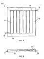
- Figures 1 and 2 show a top view and a side view (respectively) of an example of a heater mat 10 in accordance with an embodiment of the invention.
- Heater mats of this kind find particular application in the field of ice protection systems for aircraft, although other uses are envisaged.
- a heater mat according to an embodiment of the invention can be attached (e.g. fused or adhered) to an inner surface of a leading edge component of the aircraft. Heat produced by the heater mat is transferred to the leading edge, thereby preventing a build up of ice which would otherwise degrade the aerodynamic performance of the leading edge.
- the example heater mat 10 shown in Figure 1 includes an electrically resistive heater element 12.
- the heater element 12 may typically comprise a layer of electrically resistive material, such as a metal. In use, an electric current is passed through the heater element 12 to produce Joule heating.
- the heater element 12 can be made from any suitable electrically resistive material, typically a metal such as copper or aluminium. A typical thickness of the heater element can be approximately 0.1 mm in the case of a sprayed metal heater mat (see below). Other kinds of heater element (for example an element manufactured by plating) may be as thin as 0.001 mm..
- the heater element 12 is patterned in a series of interconnected strips, forming a current path.
- a different patterning can be selected in accordance with design requirements. Alternatively, the patterning may be omitted.
- the electrically resistive heater element 12 is embedded in a thermoplastic layer 16. As shown in Figure 2 , in this example, the heater element 10 is completely embedded in the thermoplastic layer 16. In other examples, portions of the heater element 12 may not be entirely embedded within the thermoplastic layer 16. For example, a portion of the heater element 12 may protrude from the thermoplastic layer 16 to allow the attachment of current carrying leads. In the present example, separate current carrying leads 14 are provided to allow connection of a completely embedded heater element to an external current supply (not shown). As illustrated in Figures 1 and 2 , the leads 14 in this example extend into the heater mat from a position at the periphery of the thermoplastic layer 16, to form terminations 15 with the heater element 12.
- the leads can be made from, for example, copper or any other suitable conductor.
- copper leads have been found to form an excellent electrical contact with a heater element embedded in a PEEK thermoplastic layer.
- a heater mat of the kind described herein can be applied (e.g. adhered) to a surface to which heating power is to be supplied.
- a surface is an inner surface of an aircraft leading edge component (for example the leading edge of a wing slat or engine nacelle).
- the heater element 12 is electrically insulated from the surface (which may be metallic) by the thermoplastic layer 16.
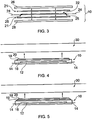
- Figure 3 illustrates an example of a process for making a heater mat 10 in accordance with an embodiment of the invention.
- the process illustrated in Figure 3 is suitable for construction of a heater mat 10 of the kind shown in Figure 1 .
- the heater mat 10 can be constructed by applying an electrically resistive heater element 22 to a first thermoplastic layer 28.
- the heater element 22 can be applied by a variety of methods, such as by a metal spraying process. If required, the heater element 22 can be patterned as described above in relation to Figure 1 . The patterning can be achieved using a masking and/or etching process.
- one or more stabilising layers 21 can be provided in the heater mat 10.
- the purpose of the stabilising layer(s) 21 is to stabilise the material making up the heater element 22 so that when the assembly is heated (as described below), migration of the heater element material is inhibited. It has also been found that the stabilising layer(s) can serve to enhance the thermal conductivity of the heater mat 10 during use.
- the stabilising layer(s) 21 can comprise a glass.
- the glass can be added as a thin layer 21 adjacent the heater element 22. Where more than one stabilising layer 21 is used, a layer of glass can be provided on either side of the heater element 22 as shown in the example of Figure 3 .
- the heater element 22 can be applied (e.g. using a metal spraying process) to a layer of glass 21 that is laid over the first thermoplastic layer 28.
- a second layer of glass 21 can optionally be laid of the sprayed metal heater element 12 and then the second layer of thermoplastic 26 can be laid over the second layer of glass 21.
- the resulting thermoplastic/stabiliser/heater/stabiliser/thermoplastic sandwich structure can then be heated as described below.
- a stabilising layer 21 such as a glass layer in the heater mat can reduce the flexibility of the mat. Accordingly, a thin layer of glass may be preferred, which can add stability during the manufacture process without having an overly adverse affect on the flexibility of the resulting heater mat.
- leads 24 can be provided to form terminations 25 with the heater element 22.
- the leads 24 can be formed using the same process as that used to provide the heater element itself. In the present example however, the leads 24 are provided as separate copper strips that are laid over the heater element 22 and the first thermoplastic layer 28.
- thermoplastic layer 26 can be applied to the assembly.
- the assembly is then heated to fuse the first (28) and second (26) layers of thermoplastic together.
- the heating can be applied by, for example, laying the assembly including the first and second thermoplastic layers on a heating plate (e.g. a metallic plate).
- a heating plate e.g. a metallic plate.
- the assembly is heated to a temperature above the melting point of the thermoplastic (e.g. when PEEK is used, the heating temperature is typically in the region of 360-380°C), to allow the fusing process to take place.
- the assembly is cooled below the glass transition temperature Tg, whereby the thermoplastic enters a glassy state. In some examples, the cooling can take place rapidly (quenching), to prevent unwanted crystallisation of the thermoplastic.
- thermoplastic layer 16 in Figure 1 a single thermoplastic layer within which the heater element 22 and optional leads 24 and stabilisation layer(s) 21 are embedded.
- the heating described above can be performed in a vacuum to prevent unwanted oxidisation.
- the process may be performed in an autoclave.
- the process can be performed by placing the assembly including then first (28) and second (26) layers of thermoplastic and the heater element 22 and leads 24 in a vacuum bag (not shown in Figure 3 ) prior to heating.
- the vacuum bag should be suitable for withstanding the desired heating temperature.
- the vacuum bag can be an aluminium vacuum bag.
- a heater mat 10 in accordance with an embodiment of the invention can be attached to a leading edge component of an aircraft, for example a wing slat.
- the heater mat 10 includes a thermoplastic outer surface.
- Thermoplastics such as PEEK are generally difficult to attach to a surface using an adhesive, since adhesives do not typically form a good bond with a PEEK surface.
- the heater mat 10 can be provided with one or more adhesive receiving layers. Examples of this are now described in relation to Figures 4 and 5 .
- the example heater mats 10 shown in Figures 4 and 5 are generally similar to the heater mat shown in Figure 1 , but each example further includes an adhesive receiving layer 18 as described above.
- the adhesive receiving layer(s) described herein can comprise a fibrous material.
- the fibrous material can be selected such that it can be effectively wetted by the thermoplastic of the thermoplastic layer.
- suitable fibrous materials include glass cloth, Kevlar, carbon fibre and S ceramic fibre.
- the adhesive receiving layer 18 is partially embedded within the thermoplastic layer 16 of the heater mat 10, and protrudes from surface of the heater mat 10.
- the protruding portion of the adhesive receiving layer 18 can thus receive an adhesive 20 (e.g. epoxy resin) for adhering the heater mat 10 to a surface 30.
- the adhesive receiving layer 18 can be added to the heater mat 10 during manufacture, by laying it over one of the layers of thermoplastic (e.g. the layer 26 or the layer 28 shown in Figure 3 ) prior to heating. During heating, the thermoplastic melts and partially receives the adhesive receiving layer 18, although a portion of the layer 18 is left to protrude from the surface of the heater mat 10 as described above.
- thermoplastic e.g. the layer 26 or the layer 28 shown in Figure 3
- an intermediate layer 19 is provided, for attaching the adhesive receiving layer 18 to the thermoplastic layer 16.
- the intermediate layer 19 typically comprises a material which forms a good bond with both the thermoplastic layer 16 and the adhesive receiving layer 18.
- the intermediate layer 19 may comprise a different thermoplastic to the thermoplastic making up the layer 16.
- the thermoplastic of the intermediate layer 19 may comprise a thermoplastic that makes a better bond with a given adhesive than does the thermoplastic of the layer 16.
- the layer 16 may comprise PEEK, while the intermediate layer 19 may comprise a polyarylsolphone.
- the heater mat 10 can be provided with more than one adhesive receiving layer.
- an adhesive receiving layer such as that described in relation to Figures 4 and 5 can be provided on both an upper and lower surface of the thermoplastic layer 16. This can allow the heater mat 10 to be adhered to the surface of an aircraft leading edge component while also allowing a further object (for example, further insulating/protective layers) to be adhered to the upper surface of the mat 10.
- one or more conducting/resistive layers can be adhered to the upper surface to form a damage/failure system. Such layers can be provided to detect electrical breakdown should the heater mat 10 suffer mechanical damage caused by outside influences (for example, mechanical failure of the structure it is attached to).
- a heater mat comprising a thermoplastic layer can be attached to a surface by heating the thermoplastic above T m , whereby the thermoplastic fuses to the surface.
- the surface which may typically be metallic
- the surface can be treated (e.g. roughened) beforehand, to improve the bond to the thermoplastic of the heater mat.
- thermoplastic layer of a heater mat can itself be used as a bonding agent, for assembling two or more parts of a leading edge structure.
- the parts to be assembled may typically comprise a skin of the leading edge and a supporting member such as a rib (e.g. an aerodynamic cardinal or rib), longeron or stringer.
- a rib e.g. an aerodynamic cardinal or rib
- the arrangement shown in Figure 6 allows the attachment of a supporting rib 40 to the inside surface of a leading edge 30 of an aircraft.
- the heater mat 10 is interposed between the rib 40 and the leading edge 30 to form the bond.
- the thermoplastic layer of the heater mat 10 has been fused (by heating the thermoplastic above its melting point T m ) to both the rib 40 and the leading edge 30.
- Bonds of this kind can, in some examples, replace the provision of conventional attachment means such as rivets.
- This has the additional advantage that no (typically metallic) rivets or such like are required to pass through a heater mat provided between the rib 40 and the leading edge 30, whereby possible short circuiting within the heater element is avoided.
- a heater mat 10 to provide a bond as shown in Figure 6 allows heating to be applied directly to the portion of the leading edge 30 below the rib 40, even though it is covered by, for example, a flange 42 of the rib 40.
- heater mats 10 have been provided over the flange 42, whereby heat produced by the heater mat is required to pass through the flange 42 before reaching the leading edge 30. Accordingly, the heating power produced in conventional arrangements is substantially reduced owing to the temperature gradient across the rib flange 42.
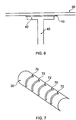
- Figure 7 schematically shows a portion of an aircraft wing slat.
- the leading edge 30 of the slat is provided with a plurality of spaced supporting ribs.
- the ribs include a plurality of cardinal ribs 70 and a plurality of aerodynamic ribs 72.
- the aerodynamic ribs 72 are spaced in between adjacent cardinal ribs 70.
- the ribs in conventional arrangements which are typically provided with flanges for attachment as discussed above, may inhibit access to many portions of the leading edge 30 for the purposes of ice-protection by heating.
- this problem can be solved, while simultaneously providing strong and robust bonding of the ribs 70, 72 to the leading edge 30.
- Leading edges structures in aircraft may typically comprise surfaces that are curved in more than one direction.
- a heater mat according to an embodiment of the invention can also be provided with a double curved shape. This can allow an ice-protection system including one or more heater mats of the kind described herein to apply even and effective heating across the surface of the leading edge.
- Figure 8 shows an example of a double curved object in conjunction with which a heater mat 10 according to an embodiment of the invention can be used.
- the double curved surface in this example is a portion of an aircraft wing slat 50. It is envisaged that heater mats according to this invention can be used with other kinds of object having a double curved surface.
- a heater mat 10 is applied to an inner surface 54 of the aircraft wing slat 50.
- the surface 54 is curved around the x-axis and the z-axis (which extends from the plane of the page). Accordingly, the surface 54 in this example is double curved.
- the heater mat 10 may be constructed in situ on the double curved surface.
- the heater mat may be constructed by applying a first thermoplastic layer to the double curved surface, then applying the heater element to the first thermoplastic layer (optionally, the first thermoplastic layer may be heated to fuse it to the surface, prior to the application of the heater element), then applying a second thermoplastic layer and heating the assembly. It should be noted that these methods may also be used to make flat heater mats in situ.
- the heater element may be applied using the methods described above (e.g. using a metal spraying process).
- each thermoplastic layer may be applied in a number of ways.
- each thermoplastic layer may be applied as a powder coating, which melts during the heating process.
- Alternative methods include flame spraying and dispersion coating.
- the thermoplastic can fuse directly to the surface 54.
- the thermoplastic can be heated to a temperature in the range 360-380°C.
- the thermoplastic On cooling (which may take place rapidly (quenching) as described above), the thermoplastic enters its glassy state, resulting in a double curved heater mat that follows the double curved shape of the surface 54.
- the heater mat can be constructed using a mould that corresponds to the intended shape.
- the moulded heater mat can then be applied to the double curved surface, using, for example, an adhesive.
- one or more adhesive receiving layers can be provided (e.g. a fibrous material such as glass cloth) to receive the adhesive.
- Adhesive receiving layers can be used in situations where it is not practical to construct the heater mat in situ (e.g. because vacuum conditions may be required). An example of this is illustrated in Figure 9 .
- thermoplastic 28 is applied to a mould section 62 bearing a double curved surface that corresponds to the intended shape.
- a second layer of thermoplastic 26 is also applied to a mould section 60 bearing a double curved surface that corresponds to the intended shape.
- the thermoplastic layers can, for example, be applied using powder coating, flame spraying or dispersion coating as described above in relation to Figure 8 .
- a heater element 22 can then be applied to one of the thermoplastic layers (in this example, the second thermoplastic layer 26), and any desired connection leads and stabilisation layers can be put in place.
- the resulting heater mat with its double curved shape can be removed from the mould and applied to the intended double curved surface as described above.
- stabilisation layers can be included in much the same way as is described above in relation to Figure 3 .
Landscapes
- Engineering & Computer Science (AREA)
- Aviation & Aerospace Engineering (AREA)
- Surface Heating Bodies (AREA)
- Resistance Heating (AREA)
- Adhesives Or Adhesive Processes (AREA)
- Carpets (AREA)
Claims (13)
- Ein Eisschutzsystem für eine Luftfahrzeuganströmflanke, das System umfassend:eine thermoelektrische Heizmatte (10), die an einer Anströmflankenkomponente eines Luftfahrzeugs anbringbar ist, die Heizmatte umfassend:ein elektrisches Widerstandsheizelement (12), das in einer thermoplastischen Lage (16) eingebettet ist, die thermoplastische Lage hat eine erste Oberfläche; undeine erste Klebstoff aufnehmende Lage (18), die auf der ersten Oberfläche der thermoplastischen Lage angeordnet ist;wobei die besagte erste Klebstoff aufnehmende Lage teilweise in der thermoplastischen Lage eingebettet ist und zumindest ein Teil davon aus der besagten Oberfläche der thermoplastischen Lage hervorsteht;wobei die Heizmatte weiter eine stabilisierende Lage (21) umfasst, die in der thermoplastischen Lage eingebettet ist.
- Das Eisschutzsystem für eine Luftfahrzeuganströmflanke nach Anspruch 1, umfassend eine zweite Klebstoff aufnehmende Lage, die an einer Oberfläche der thermoplastischen Lage angeordnet ist, und wobei die zweite Klebstoff aufnehmende Lage auf einer Oberfläche der thermoplastischen Lage angeordnet ist, die zu der ersten Oberfläche gegenüberliegend ist.
- Das Eisschutzsystem für eine Luftfahrzeuganströmflanke nach Anspruch 2, wobei die zweite Klebstoff aufnehmende Lage teilweise in der thermoplastischen Lage eingebettet ist und ein Teil davon aus der Oberfläche der thermoplastischen Lage, die zu der ersten Oberfläche gegenüberliegend ist, hervorsteht.
- Das Eisschutzsystem für eine Luftfahrzeuganströmflanke nach irgendeinem der vorhergehenden Ansprüche, wobei die oder jede Klebstoff aufnehmende Lage Fasermaterial umfasst.
- Eine Baugruppe, umfassend eine Luftfahrzeuganströmflankenkomponente (30) und das Eisschutzsystem für eine Luftfahrzeuganströmflanke einem der vorhergehenden Ansprüche.
- Die Baugruppe nach Anspruch 5, wobei die Luftfahrzeuganströmflankenkomponente eine Anströmflanke einer Luftfahrzeugtragfläche umfasst.
- Ein Luftfahrzeug, umfassend die Baugruppe nach Anspruch 5 oder Anspruch 6.
- Ein Verfahren zur Herstellung eines Eisschutzsystems für eine Luftfahrzeuganströmflanke, das Verfahren umfassend:Herstellen eines thermoelektrischen Heizmatte (10) durch Einbetten eines elektrischen Widerstandheizelements (12) in eine thermoplastische Lage (16), die thermoplastische Lage aufweisend eine erste Oberfläche; undAnordnen einer ersten Klebstoff aufnehmenden Lage (18) auf der ersten Oberfläche der thermoplastischen Lage,wobei das Anordnen der besagten ersten Klebstoff aufnehmenden Lage teilweises Einbetten der besagten zweiten Klebstofflage in der thermoplastischen Lage, sodass zumindest ein Teil davon aus einer Oberfläche der thermoplastischen Lage hervorsteht,wobei das Herstellen der Heizmatte ein Hinzufügen einer stabilisierenden Lage (21) zu der Matte umfasst.
- Das Verfahren nach Anspruch 8, umfassend:Anordnen einer zweiten Klebstoff aufnehmenden Lage auf einer Oberfläche der thermoplastischen Lage, undAnordnen der zweiten Klebstoff aufnehmenden Lage auf der Oberfläche der thermoplastischen Lage, die der ersten Oberfläche gegenüberliegend ist.
- Das Verfahren nach Anspruch 9, wobei das besagte Anordnen der zweiten Klebstoff aufnehmenden Lage ein teilweises Einbetten der besagten zweiten Klebstoff aufnehmenden Lage in die thermoplastische Lage umfasst, sodass es aus der Oberfläche der thermoplastischen Lage, die der ersten Oberfläche gegenüberliegend ist, hervorsteht.
- Das Verfahren nach einem der Ansprüche 8 bis 10, wobei die oder jede Klebstoff aufnehmende Lage Fasermaterial umfasst.
- Das Verfahren nach einem der Ansprüche 8 bis 11 weiter umfassend:Aufbringen eines Klebstoffs auf der ersten Klebstoff aufnehmenden Lage (18); undVerwenden des Klebstoffs, um die Heizmatte an der Anströmflankenkomponente (30) für ein Luftfahrzeug anzubringen; undAufbringen eines Klebstoffs auf die zweite Klebstoff aufnehmende Lage; undVerwenden des Klebstoffs, um einen weiteren Gegenstand (40) an der Heizmatte anzubringen;wobei der weitere Gegenstand eine Stützrippe der Anströmflankenkomponente ist.
- Das Verfahren nach einem der Ansprüche 8 bis 12, wobei das Herstellen der Heizmatte das Verwenden einer Form zum Produzieren einer geformten thermoplastischen Lage umfasst, aufweisend eine doppelt gekrümmte Form, die zu einer doppelt gekrümmten Oberfläche einer Luftfahrzeuganströmflankenkomponente entspricht, auf welche die Heizmatte aufzubringen ist.
Applications Claiming Priority (2)
| Application Number | Priority Date | Filing Date | Title |
|---|---|---|---|
| GB0720415.9A GB2453769B (en) | 2007-10-18 | 2007-10-18 | An aircraft leading edge thermoplastic heating mat |
| PCT/GB2008/003500 WO2009050460A1 (en) | 2007-10-18 | 2008-10-15 | Bonding of thermoplastics |
Publications (2)
| Publication Number | Publication Date |
|---|---|
| EP2218302A1 EP2218302A1 (de) | 2010-08-18 |
| EP2218302B1 true EP2218302B1 (de) | 2012-04-25 |
Family
ID=38814073
Family Applications (1)
| Application Number | Title | Priority Date | Filing Date |
|---|---|---|---|
| EP08840048A Active EP2218302B1 (de) | 2007-10-18 | 2008-10-15 | Bonden von thermoplasten |
Country Status (6)
| Country | Link |
|---|---|
| US (1) | US8523113B2 (de) |
| EP (1) | EP2218302B1 (de) |
| AT (1) | ATE555634T1 (de) |
| ES (1) | ES2384747T3 (de) |
| GB (1) | GB2453769B (de) |
| WO (1) | WO2009050460A1 (de) |
Cited By (1)
| Publication number | Priority date | Publication date | Assignee | Title |
|---|---|---|---|---|
| EP4426055A3 (de) * | 2023-02-13 | 2024-09-25 | Goodrich Corporation | Mehrschichtige struktur mit kohlenstoffnanoröhrchenheizern |
Families Citing this family (21)
| Publication number | Priority date | Publication date | Assignee | Title |
|---|---|---|---|---|
| GB2477337B (en) | 2010-01-29 | 2011-12-07 | Gkn Aerospace Services Ltd | Electrical apparatus |
| GB2477338B (en) * | 2010-01-29 | 2011-12-07 | Gkn Aerospace Services Ltd | Electrothermal heater |
| GB2477340B (en) | 2010-01-29 | 2011-12-07 | Gkn Aerospace Services Ltd | Electrothermal heater mat |
| DE102012002132A1 (de) | 2012-02-03 | 2013-08-08 | Airbus Operations Gmbh | Vereisungsschutzsystem für ein Flugzeug und Verfahren zum Betreiben eines Vereisungsschutzsystems |
| US8998144B2 (en) * | 2012-02-06 | 2015-04-07 | Textron Innovations Inc. | Thermal insulation barrier for an aircraft de-icing heater |
| US9193466B2 (en) | 2012-07-13 | 2015-11-24 | Mra Systems, Inc. | Aircraft ice protection system and method |
| CN105523186B (zh) * | 2015-12-11 | 2018-08-14 | 中国人民解放军国防科学技术大学 | 一种用于除湿/霜/冰的合成热射流激励器及应用 |
| CA3056400A1 (en) | 2017-02-06 | 2018-08-09 | Kjell Lindskog | Method and arrangement related to heating of wings in wind power plants or other devices |
| GB2566550B (en) | 2017-09-19 | 2022-07-13 | Gkn Aerospace Services Ltd | Electrothermal heater mat and method of manufacture thereof |
| CN110198574B (zh) * | 2018-02-27 | 2022-08-09 | 新疆金风科技股份有限公司 | 防雷电热融冰装置及其制造方法、叶片和风力发电机组 |
| GB2574184B (en) * | 2018-03-29 | 2020-12-02 | Gkn Aerospace Services Ltd | Ice removal system |
| BR112020021755B1 (pt) * | 2018-04-24 | 2022-07-05 | Qarbon Aerospace (Foundation), Llc | Aeroestrutura aquecida |
| KR102356284B1 (ko) | 2018-05-03 | 2022-02-09 | 카본 에어로스페이스 (파운데이션), 엘엘씨 | 국부적인 절연 층을 갖는 열가소성 항공기 구조물 및 항공기 구조물을 형성하기 위한 방법 |
| US11273897B2 (en) | 2018-07-03 | 2022-03-15 | Goodrich Corporation | Asymmetric surface layer for floor panels |
| US11376811B2 (en) | 2018-07-03 | 2022-07-05 | Goodrich Corporation | Impact and knife cut resistant pre-impregnated woven fabric for aircraft heated floor panels |
| US10920994B2 (en) | 2018-07-03 | 2021-02-16 | Goodrich Corporation | Heated floor panels |
| US10875623B2 (en) | 2018-07-03 | 2020-12-29 | Goodrich Corporation | High temperature thermoplastic pre-impregnated structure for aircraft heated floor panel |
| US10899427B2 (en) | 2018-07-03 | 2021-01-26 | Goodrich Corporation | Heated floor panel with impact layer |
| US20220117045A1 (en) * | 2019-02-01 | 2022-04-14 | Kjell Lindskog | Apparatus and method for a heating mat |
| TW202450366A (zh) * | 2023-04-24 | 2024-12-16 | 美商瓦特洛威電子製造公司 | 用於薄壁基板的單片層狀加熱器 |
| FR3161900A1 (fr) | 2024-05-02 | 2025-11-07 | Safran Aerosystems | Tapis de protection contre le givre, ensemble comprenant un tel tapis et un procédé de fabrication d’un tel tapis |
Family Cites Families (10)
| Publication number | Priority date | Publication date | Assignee | Title |
|---|---|---|---|---|
| FR2202810B1 (de) * | 1972-10-16 | 1975-03-28 | Kleber Colombes | |
| US4875644A (en) * | 1988-10-14 | 1989-10-24 | The B. F. Goodrich Company | Electro-repulsive separation system for deicing |
| EP0633836B1 (de) * | 1992-03-30 | 1997-02-19 | United Technologies Corporation | Heizvorrichtung zum thermoplastischen schweissen |
| US5412181A (en) | 1993-12-27 | 1995-05-02 | The B. F. Goodrich Company | Variable power density heating using stranded resistance wire |
| EP0680878B1 (de) | 1994-04-13 | 1999-12-22 | The B.F. Goodrich Company | Elektrothermisches System zur Enteisung |
| FR2736500A1 (fr) | 1995-07-03 | 1997-01-10 | Gouthez Philippe | Element chauffant a matrice thermoplastique |
| JPH10199664A (ja) * | 1997-01-16 | 1998-07-31 | Asahi Corp | 電熱板補護シート |
| CN1183805C (zh) | 1999-12-10 | 2005-01-05 | 热离子体系国际公司 | 热塑性层状织物加热器及其制造方法 |
| DE10254622A1 (de) | 2002-11-22 | 2004-09-02 | Hueck Folien Gesellschaft M.B.H. | Hochbelastbar, beständige, flexible Folie |
| GB2438389A (en) * | 2006-05-23 | 2007-11-28 | Gkn Aerospace Transparency Sys | Heating system for leading edge of aircraft |
-
2007
- 2007-10-18 GB GB0720415.9A patent/GB2453769B/en active Active
-
2008
- 2008-10-15 US US12/738,371 patent/US8523113B2/en active Active
- 2008-10-15 ES ES08840048T patent/ES2384747T3/es active Active
- 2008-10-15 EP EP08840048A patent/EP2218302B1/de active Active
- 2008-10-15 WO PCT/GB2008/003500 patent/WO2009050460A1/en not_active Ceased
- 2008-10-15 AT AT08840048T patent/ATE555634T1/de active
Cited By (1)
| Publication number | Priority date | Publication date | Assignee | Title |
|---|---|---|---|---|
| EP4426055A3 (de) * | 2023-02-13 | 2024-09-25 | Goodrich Corporation | Mehrschichtige struktur mit kohlenstoffnanoröhrchenheizern |
Also Published As
| Publication number | Publication date |
|---|---|
| GB0720415D0 (en) | 2007-11-28 |
| US8523113B2 (en) | 2013-09-03 |
| GB2453769A (en) | 2009-04-22 |
| GB2453769B (en) | 2012-09-05 |
| US20100308173A1 (en) | 2010-12-09 |
| EP2218302A1 (de) | 2010-08-18 |
| ATE555634T1 (de) | 2012-05-15 |
| WO2009050460A1 (en) | 2009-04-23 |
| ES2384747T3 (es) | 2012-07-11 |
Similar Documents
| Publication | Publication Date | Title |
|---|---|---|
| EP2218302B1 (de) | Bonden von thermoplasten | |
| EP2213139B1 (de) | Strukturbondungsanordnung | |
| US8006934B2 (en) | Heating architecture for a composite fairing | |
| US8981266B2 (en) | Electrical apparatus | |
| US4737618A (en) | Heating element for a defrosting device for a wing structure, such a device and a process for obtaining same | |
| US7789620B2 (en) | Heater assembly for deicing and/or anti-icing a component | |
| US8807483B2 (en) | Electrothermal heater mat | |
| US10252806B2 (en) | Electrothermal heater mat | |
| US20120298803A1 (en) | Electrothermal heater | |
| JP2021151865A (ja) | 一体型の加熱要素を備えた複合航空機構造 | |
| US8993940B2 (en) | Dielectric component with electrical connection | |
| EP2390182B1 (de) | Flugzeugheizsystem | |
| JP2000356358A (ja) | 特に航空機内の床面プレート用のプレート構成部材 | |
| EP0633836B1 (de) | Heizvorrichtung zum thermoplastischen schweissen | |
| GB2453933A (en) | Aircraft leading edge ice protection system comprising a thermoplastic heater mat | |
| US20090188904A1 (en) | Fault Tolerant Heater Circuit | |
| US12162245B2 (en) | Resin film |
Legal Events
| Date | Code | Title | Description |
|---|---|---|---|
| PUAI | Public reference made under article 153(3) epc to a published international application that has entered the european phase |
Free format text: ORIGINAL CODE: 0009012 |
|
| 17P | Request for examination filed |
Effective date: 20100518 |
|
| AK | Designated contracting states |
Kind code of ref document: A1 Designated state(s): AT BE BG CH CY CZ DE DK EE ES FI FR GB GR HR HU IE IS IT LI LT LU LV MC MT NL NO PL PT RO SE SI SK TR |
|
| AX | Request for extension of the european patent |
Extension state: AL BA MK RS |
|
| DAX | Request for extension of the european patent (deleted) | ||
| REG | Reference to a national code |
Ref country code: DE Ref legal event code: R079 Ref document number: 602008015256 Country of ref document: DE Free format text: PREVIOUS MAIN CLASS: H05B0003360000 Ipc: H05B0003280000 |
|
| GRAP | Despatch of communication of intention to grant a patent |
Free format text: ORIGINAL CODE: EPIDOSNIGR1 |
|
| RIC1 | Information provided on ipc code assigned before grant |
Ipc: H05B 3/36 20060101ALI20111005BHEP Ipc: H05B 3/28 20060101AFI20111005BHEP Ipc: B64D 15/12 20060101ALI20111005BHEP |
|
| GRAS | Grant fee paid |
Free format text: ORIGINAL CODE: EPIDOSNIGR3 |
|
| GRAA | (expected) grant |
Free format text: ORIGINAL CODE: 0009210 |
|
| AK | Designated contracting states |
Kind code of ref document: B1 Designated state(s): AT BE BG CH CY CZ DE DK EE ES FI FR GB GR HR HU IE IS IT LI LT LU LV MC MT NL NO PL PT RO SE SI SK TR |
|
| REG | Reference to a national code |
Ref country code: GB Ref legal event code: FG4D |
|
| REG | Reference to a national code |
Ref country code: CH Ref legal event code: EP |
|
| REG | Reference to a national code |
Ref country code: AT Ref legal event code: REF Ref document number: 555634 Country of ref document: AT Kind code of ref document: T Effective date: 20120515 |
|
| REG | Reference to a national code |
Ref country code: IE Ref legal event code: FG4D |
|
| REG | Reference to a national code |
Ref country code: SE Ref legal event code: TRGR |
|
| REG | Reference to a national code |
Ref country code: DE Ref legal event code: R096 Ref document number: 602008015256 Country of ref document: DE Effective date: 20120621 |
|
| REG | Reference to a national code |
Ref country code: ES Ref legal event code: FG2A Ref document number: 2384747 Country of ref document: ES Kind code of ref document: T3 Effective date: 20120711 |
|
| REG | Reference to a national code |
Ref country code: NL Ref legal event code: T3 |
|
| REG | Reference to a national code |
Ref country code: AT Ref legal event code: MK05 Ref document number: 555634 Country of ref document: AT Kind code of ref document: T Effective date: 20120425 |
|
| LTIE | Lt: invalidation of european patent or patent extension |
Effective date: 20120425 |
|
| PG25 | Lapsed in a contracting state [announced via postgrant information from national office to epo] |
Ref country code: FI Free format text: LAPSE BECAUSE OF FAILURE TO SUBMIT A TRANSLATION OF THE DESCRIPTION OR TO PAY THE FEE WITHIN THE PRESCRIBED TIME-LIMIT Effective date: 20120425 Ref country code: NO Free format text: LAPSE BECAUSE OF FAILURE TO SUBMIT A TRANSLATION OF THE DESCRIPTION OR TO PAY THE FEE WITHIN THE PRESCRIBED TIME-LIMIT Effective date: 20120725 Ref country code: CY Free format text: LAPSE BECAUSE OF FAILURE TO SUBMIT A TRANSLATION OF THE DESCRIPTION OR TO PAY THE FEE WITHIN THE PRESCRIBED TIME-LIMIT Effective date: 20120425 Ref country code: LT Free format text: LAPSE BECAUSE OF FAILURE TO SUBMIT A TRANSLATION OF THE DESCRIPTION OR TO PAY THE FEE WITHIN THE PRESCRIBED TIME-LIMIT Effective date: 20120425 Ref country code: PL Free format text: LAPSE BECAUSE OF FAILURE TO SUBMIT A TRANSLATION OF THE DESCRIPTION OR TO PAY THE FEE WITHIN THE PRESCRIBED TIME-LIMIT Effective date: 20120425 Ref country code: IS Free format text: LAPSE BECAUSE OF FAILURE TO SUBMIT A TRANSLATION OF THE DESCRIPTION OR TO PAY THE FEE WITHIN THE PRESCRIBED TIME-LIMIT Effective date: 20120825 |
|
| PG25 | Lapsed in a contracting state [announced via postgrant information from national office to epo] |
Ref country code: LV Free format text: LAPSE BECAUSE OF FAILURE TO SUBMIT A TRANSLATION OF THE DESCRIPTION OR TO PAY THE FEE WITHIN THE PRESCRIBED TIME-LIMIT Effective date: 20120425 Ref country code: GR Free format text: LAPSE BECAUSE OF FAILURE TO SUBMIT A TRANSLATION OF THE DESCRIPTION OR TO PAY THE FEE WITHIN THE PRESCRIBED TIME-LIMIT Effective date: 20120726 Ref country code: SI Free format text: LAPSE BECAUSE OF FAILURE TO SUBMIT A TRANSLATION OF THE DESCRIPTION OR TO PAY THE FEE WITHIN THE PRESCRIBED TIME-LIMIT Effective date: 20120425 Ref country code: HR Free format text: LAPSE BECAUSE OF FAILURE TO SUBMIT A TRANSLATION OF THE DESCRIPTION OR TO PAY THE FEE WITHIN THE PRESCRIBED TIME-LIMIT Effective date: 20120425 Ref country code: PT Free format text: LAPSE BECAUSE OF FAILURE TO SUBMIT A TRANSLATION OF THE DESCRIPTION OR TO PAY THE FEE WITHIN THE PRESCRIBED TIME-LIMIT Effective date: 20120827 |
|
| PG25 | Lapsed in a contracting state [announced via postgrant information from national office to epo] |
Ref country code: AT Free format text: LAPSE BECAUSE OF FAILURE TO SUBMIT A TRANSLATION OF THE DESCRIPTION OR TO PAY THE FEE WITHIN THE PRESCRIBED TIME-LIMIT Effective date: 20120425 Ref country code: CZ Free format text: LAPSE BECAUSE OF FAILURE TO SUBMIT A TRANSLATION OF THE DESCRIPTION OR TO PAY THE FEE WITHIN THE PRESCRIBED TIME-LIMIT Effective date: 20120425 Ref country code: RO Free format text: LAPSE BECAUSE OF FAILURE TO SUBMIT A TRANSLATION OF THE DESCRIPTION OR TO PAY THE FEE WITHIN THE PRESCRIBED TIME-LIMIT Effective date: 20120425 Ref country code: SK Free format text: LAPSE BECAUSE OF FAILURE TO SUBMIT A TRANSLATION OF THE DESCRIPTION OR TO PAY THE FEE WITHIN THE PRESCRIBED TIME-LIMIT Effective date: 20120425 Ref country code: EE Free format text: LAPSE BECAUSE OF FAILURE TO SUBMIT A TRANSLATION OF THE DESCRIPTION OR TO PAY THE FEE WITHIN THE PRESCRIBED TIME-LIMIT Effective date: 20120425 Ref country code: DK Free format text: LAPSE BECAUSE OF FAILURE TO SUBMIT A TRANSLATION OF THE DESCRIPTION OR TO PAY THE FEE WITHIN THE PRESCRIBED TIME-LIMIT Effective date: 20120425 |
|
| PLBE | No opposition filed within time limit |
Free format text: ORIGINAL CODE: 0009261 |
|
| STAA | Information on the status of an ep patent application or granted ep patent |
Free format text: STATUS: NO OPPOSITION FILED WITHIN TIME LIMIT |
|
| 26N | No opposition filed |
Effective date: 20130128 |
|
| REG | Reference to a national code |
Ref country code: DE Ref legal event code: R097 Ref document number: 602008015256 Country of ref document: DE Effective date: 20130128 |
|
| PG25 | Lapsed in a contracting state [announced via postgrant information from national office to epo] |
Ref country code: MC Free format text: LAPSE BECAUSE OF NON-PAYMENT OF DUE FEES Effective date: 20121031 |
|
| REG | Reference to a national code |
Ref country code: CH Ref legal event code: PL |
|
| GBPC | Gb: european patent ceased through non-payment of renewal fee |
Effective date: 20121015 |
|
| REG | Reference to a national code |
Ref country code: IE Ref legal event code: MM4A |
|
| PG25 | Lapsed in a contracting state [announced via postgrant information from national office to epo] |
Ref country code: CH Free format text: LAPSE BECAUSE OF NON-PAYMENT OF DUE FEES Effective date: 20121031 Ref country code: IE Free format text: LAPSE BECAUSE OF NON-PAYMENT OF DUE FEES Effective date: 20121015 Ref country code: LI Free format text: LAPSE BECAUSE OF NON-PAYMENT OF DUE FEES Effective date: 20121031 Ref country code: BG Free format text: LAPSE BECAUSE OF FAILURE TO SUBMIT A TRANSLATION OF THE DESCRIPTION OR TO PAY THE FEE WITHIN THE PRESCRIBED TIME-LIMIT Effective date: 20120725 |
|
| REG | Reference to a national code |
Ref country code: GB Ref legal event code: S28 Free format text: APPLICATION FILED |
|
| PG25 | Lapsed in a contracting state [announced via postgrant information from national office to epo] |
Ref country code: MT Free format text: LAPSE BECAUSE OF FAILURE TO SUBMIT A TRANSLATION OF THE DESCRIPTION OR TO PAY THE FEE WITHIN THE PRESCRIBED TIME-LIMIT Effective date: 20120425 |
|
| REG | Reference to a national code |
Ref country code: GB Ref legal event code: S28 Free format text: RESTORATION ALLOWED Effective date: 20131219 |
|
| PG25 | Lapsed in a contracting state [announced via postgrant information from national office to epo] |
Ref country code: TR Free format text: LAPSE BECAUSE OF FAILURE TO SUBMIT A TRANSLATION OF THE DESCRIPTION OR TO PAY THE FEE WITHIN THE PRESCRIBED TIME-LIMIT Effective date: 20120425 |
|
| PG25 | Lapsed in a contracting state [announced via postgrant information from national office to epo] |
Ref country code: LU Free format text: LAPSE BECAUSE OF NON-PAYMENT OF DUE FEES Effective date: 20121015 |
|
| PG25 | Lapsed in a contracting state [announced via postgrant information from national office to epo] |
Ref country code: HU Free format text: LAPSE BECAUSE OF FAILURE TO SUBMIT A TRANSLATION OF THE DESCRIPTION OR TO PAY THE FEE WITHIN THE PRESCRIBED TIME-LIMIT Effective date: 20081015 |
|
| REG | Reference to a national code |
Ref country code: FR Ref legal event code: PLFP Year of fee payment: 8 |
|
| REG | Reference to a national code |
Ref country code: FR Ref legal event code: PLFP Year of fee payment: 9 |
|
| PG25 | Lapsed in a contracting state [announced via postgrant information from national office to epo] |
Ref country code: GB Free format text: THE PATENT HAS BEEN ANNULLED BY A DECISION OF A NATIONAL AUTHORITY Effective date: 20121015 |
|
| PGFP | Annual fee paid to national office [announced via postgrant information from national office to epo] |
Ref country code: ES Payment date: 20160913 Year of fee payment: 9 |
|
| PGFP | Annual fee paid to national office [announced via postgrant information from national office to epo] |
Ref country code: NL Payment date: 20161010 Year of fee payment: 9 |
|
| PGFP | Annual fee paid to national office [announced via postgrant information from national office to epo] |
Ref country code: SE Payment date: 20161011 Year of fee payment: 9 Ref country code: IT Payment date: 20161024 Year of fee payment: 9 |
|
| REG | Reference to a national code |
Ref country code: FR Ref legal event code: PLFP Year of fee payment: 10 |
|
| REG | Reference to a national code |
Ref country code: SE Ref legal event code: EUG |
|
| REG | Reference to a national code |
Ref country code: NL Ref legal event code: MM Effective date: 20171101 |
|
| PG25 | Lapsed in a contracting state [announced via postgrant information from national office to epo] |
Ref country code: NL Free format text: LAPSE BECAUSE OF NON-PAYMENT OF DUE FEES Effective date: 20171101 |
|
| PG25 | Lapsed in a contracting state [announced via postgrant information from national office to epo] |
Ref country code: SE Free format text: LAPSE BECAUSE OF NON-PAYMENT OF DUE FEES Effective date: 20171016 |
|
| REG | Reference to a national code |
Ref country code: FR Ref legal event code: PLFP Year of fee payment: 11 |
|
| PG25 | Lapsed in a contracting state [announced via postgrant information from national office to epo] |
Ref country code: IT Free format text: LAPSE BECAUSE OF NON-PAYMENT OF DUE FEES Effective date: 20171015 |
|
| REG | Reference to a national code |
Ref country code: ES Ref legal event code: FD2A Effective date: 20181221 |
|
| PG25 | Lapsed in a contracting state [announced via postgrant information from national office to epo] |
Ref country code: ES Free format text: LAPSE BECAUSE OF NON-PAYMENT OF DUE FEES Effective date: 20171016 |
|
| REG | Reference to a national code |
Ref country code: DE Ref legal event code: R082 Ref document number: 602008015256 Country of ref document: DE Representative=s name: KARO IP PATENTANWAELTE PARTG MBB, DE Ref country code: DE Ref legal event code: R082 Ref document number: 602008015256 Country of ref document: DE Ref country code: DE Ref legal event code: R082 Ref document number: 602008015256 Country of ref document: DE Representative=s name: KARO IP PATENTANWAELTE KAHLHOEFER ROESSLER KRE, DE |
|
| REG | Reference to a national code |
Ref country code: DE Ref legal event code: R082 Ref document number: 602008015256 Country of ref document: DE Representative=s name: KARO IP PATENTANWAELTE PARTG MBB, DE Ref country code: DE Ref legal event code: R082 Ref document number: 602008015256 Country of ref document: DE Representative=s name: KARO IP PATENTANWAELTE KAHLHOEFER ROESSLER KRE, DE |
|
| P01 | Opt-out of the competence of the unified patent court (upc) registered |
Effective date: 20230526 |
|
| PGFP | Annual fee paid to national office [announced via postgrant information from national office to epo] |
Ref country code: BE Payment date: 20250917 Year of fee payment: 18 Ref country code: GB Payment date: 20250828 Year of fee payment: 18 |
|
| PGFP | Annual fee paid to national office [announced via postgrant information from national office to epo] |
Ref country code: FR Payment date: 20250908 Year of fee payment: 18 |
|
| PGFP | Annual fee paid to national office [announced via postgrant information from national office to epo] |
Ref country code: DE Payment date: 20250902 Year of fee payment: 18 |