EP2216990A2 - Cabinet structure for display apparatus - Google Patents
Cabinet structure for display apparatus Download PDFInfo
- Publication number
- EP2216990A2 EP2216990A2 EP10152414A EP10152414A EP2216990A2 EP 2216990 A2 EP2216990 A2 EP 2216990A2 EP 10152414 A EP10152414 A EP 10152414A EP 10152414 A EP10152414 A EP 10152414A EP 2216990 A2 EP2216990 A2 EP 2216990A2
- Authority
- EP
- European Patent Office
- Prior art keywords
- liquid crystal
- cabinet
- convex
- curved
- press rib
- Prior art date
- Legal status (The legal status is an assumption and is not a legal conclusion. Google has not performed a legal analysis and makes no representation as to the accuracy of the status listed.)
- Granted
Links
- 239000004973 liquid crystal related substance Substances 0.000 claims abstract description 136
- 238000003825 pressing Methods 0.000 claims description 3
- 238000000034 method Methods 0.000 description 5
- 239000011347 resin Substances 0.000 description 4
- 229920005989 resin Polymers 0.000 description 4
- 238000010586 diagram Methods 0.000 description 3
- 238000004519 manufacturing process Methods 0.000 description 3
- 239000007788 liquid Substances 0.000 description 2
- 230000000694 effects Effects 0.000 description 1
- 230000004048 modification Effects 0.000 description 1
- 238000012986 modification Methods 0.000 description 1
- 125000006850 spacer group Chemical group 0.000 description 1
Images

Classifications
-
- H—ELECTRICITY
- H04—ELECTRIC COMMUNICATION TECHNIQUE
- H04N—PICTORIAL COMMUNICATION, e.g. TELEVISION
- H04N5/00—Details of television systems
- H04N5/64—Constructional details of receivers, e.g. cabinets or dust covers
Definitions
- the present invention relates to a cabinet structure for a display apparatus such as a liquid crystal television.
- a conventional cabinet structure for a display apparatus such as a liquid crystal television is such that a liquid crystal module provided with a liquid crystal panel is fitted in a box-shaped cabinet composed of a front cabinet and a rear cabinet.
- a front cabinet In the front cabinet, there is provided an open window portion through which a display screen of the liquid crystal panel is exposed.
- the liquid crystal module is built as a unit provided with components such as a liquid crystal panel, a drive circuit for driving the liquid crystal panel, a tuner for receiving a broadcast signal, and a circuit board having, for example, a control circuit for controlling various parts mounted thereon.
- a liquid crystal module is screwed to a fitting boss provided in the front cabinet.
- a press rib provided on the front-cabinet side is pressed against a bezel provided along the outer circumferential edge of the display screen of the liquid crystal panel, and then the liquid crystal module is screwed to the fitting boss.
- the front cabinet is made of resin, and thus deformation such as warp or flexure may occur in the front cabinet. Defo rmation occurred in the front cabinet leads to undulation in the length direction of the press rib, which causes a gap to occur between the liquid crystal module and the press rib. Such a gap causes vibration noise. A gap between the liquid crystal module and the press rib will cause a gap to occur between the liquid crystal panel and the front cabinet, and this deteriorates the appearance. Furthermore, vibration noise annoys the audience, and thus further deteriorates the commercial value of the apparatus.
- a cabinet structure in which cabinet deformation and vibration noise are prevented by providing moment force generation means that is integrally formed with a front cabinet to generate a moment force to bring an open window portion on the front-cabinet side into an intimate contact with the liquid crystal-panel side in the fabrication process, to thereby improve the appearance of the front cabinet and the display screen of the liquid crystal panel when they are assembled together see, for example, Patent Literature 1
- a display apparatus structured such that an end of a press rib is formed narrower toward the end such that the press rib and a liquid crystal module are in an intimate contact with each other in a line-contact manner, to thereby prevent a gap from occurring between the liquid crystal module and the press rib to cause vibration noise see, for example, Patent Literature 2.
- Patent Literature 1 JP-A-2007-293129
- Patent Literature 2 JP-A-2008-309890
- the press rib in a shape that is narrower toward its end (tapered toward its end) and bring the press rib into an intimate contact with the liquid crystal module, but with respect to display apparatuses such as liquid crystal televisions that have been increasing in size, it is difficult to follow the modification of a wide front cabinet and bring a press rib into a uniform contact with the wide front cabinet by using a method of simply bringing the press rib into an intimate contact with the front cabinet in a line-contact manner.
- a simpler cabinet structure is needed in which the gap between the front cabinet and the liquid crystal panel is made uniform such that a preferable appearance of the liquid crystal panel and the front cabinet can be achieved when they are assembled together, and such that, even when the cabinet structure is applied to a display apparatus having a large display screen, vibration noise can be effectively prevented from occurring where the front cabinet and the liquid crystal module are in contact with each other.
- an object of the present invention is to provide a simpler cabinet structure for a display apparatus that is capable of achieving a preferable appearance of the display screen of the liquid crystal panel and the cabinet when they are assembled together, and that is also capable of effectively preventing the occurrence of vibration noise.
- a cabinet structure for a display apparatus is provided with: a liquid crystal module provided with a liquid crystal panel; a front cabinet provided with an open window portion through which a display screen of the liquid crystal panel is exposed; and a rear cabinet that is joined to the front cabinet to form a cabinet main body in which the liquid crystal module is accommodated.
- the cabinet structure is characterized in that a press rib is provided in four sides of the front cabinet surrounding the open window portion of the front cabinet so as to be in contact with a bezel provided along an outer circumferential edge of the liquid crystal panel, that the liquid crystal module is fitted with the press rib pressed against the bezel, and that the press rib is formed as a convex-curved press rib in which a contact portion at which the convex-curved press rib is in contact with the bezel is curved along a length direction of the convex-curved press rib to be convex.
- the above described cabinet structure for a display apparatus be further provided with: a plurality of fitting bosses provided at predetermined intervals outside the press rib on a rear surface of the front cabinet; and a fitting member provided on a side of the liquid crystal module to protrude therefrom to be engaged with the fitting bosses.
- the liquid crystal module is fixed to the front cabinet by fixing the fitting member to the fitting bosses by screwing screws engaged in the fitting member into screw holes formed in the fitting bosses, with the convex-curved press rib pressed against the bezel by strongly pressing a middle portion of the convex-curved press rib in a length direction thereof.
- a cabinet structure for a display apparatus can be obtained that is capable of realizing a preferable appearance after assembly and that is also capable of preventing the occurrence of vibration noise, even when the structure is applied to a display apparatus having a large-screened liquid crystal panel.
- the convex-curved press rib be curved to a degree that does not cause strain in the display screen of the liquid crystal panel.
- this structure no strain occurs in the display screen even if the middle portion of the convex-curved press rib in the length direction thereof is strongly pressed against the bezel, and thus can be realized a cabinet structure for a liquid crystal panel that has a preferable appearance and that is free from vibration noise.
- a contact portion of the open window portion at which the open window portion is in contact with the liquid crystal panel be formed as a curved window portion that is curved to a same degree as the convex-curved press rib.
- a contact portion of the convex-curved press rib be tapered toward an end thereof.
- a liquid crystal module is fitted to a front cabinet that is provided with an opening portion through which a display screen of the liquid crystal panel is exposed, a press rib is provided in four sides surrounding the open window portion of the front cabinet so as to be in contact with a bezel provided along an outer circumferential edge of the liquid crystal panel, and the press rib is formed as a convex-curved press rib curved along a length direction thereof to be convex.
- the display apparatus 1 of this embodiment is a display apparatus using a liquid crystal panel, and is provided with, as shown in Fig. 1 , a front cabinet 2 and a liquid crystal module 3 that forms a display screen by exposing a liquid crystal panel 31 through an open window portion of the front cabinet 2.
- a rear cabinet (not shown) is fitted to the rear side of the front cabinet 2.
- the display apparatus 1 has a cabinet structure provided with the liquid crystal module 3 provided with the liquid crystal panel 31, a front cabinet 2 provided with an open window portion through which the display screen of the liquid crystal panel 31 is exposed, and a rear cabinet that is united with the front cabinet 2 to form the cabinet main body in which the liquid crystal module 3 is accommodated.
- the liquid crystal module 3 is built as a unit provided with, in addition to the liquid crystal panel 31, a drive circuit for driving the liquid crystal panel 31, a tuner for receiving a broadcast signal, a circuit board on which, for example, a control circuit for controlling various portions is mounted, and the like. Furtherm ore, a bezel is provided along an outer circumferential edge of the liquid crystal panel 31, and a press rib that is in contact with the bezel is provided in four sides of the front cabinet 2 surrounding the open window portion of the front cabinet 2. A description will be given of this cabinet structure with reference to Figs 2 , 3A, 3B, and 3C .
- Fig. 2 is a sectional view taken along line II-II of Fig. 1 , showing that the front cabinet 2 and the liquid crystal module 3 are fixed to each other in a state in which the press rib 4 provided in the four sides surrounding the open window portion of the front cabinet 2 is in contact with the bezel 32 provided along the outer circumferential edge of the liquid crystal panel 31.
- the cabinet structure of this embodiment is one for a display apparatus that helps achieve a preferable appearance of the liquid crystal panel 31 and the cabinet when they are assembled together, and that even helps prevent occurrence of vibration noise.
- the press rib 4 is formed as a convex-curved press rib whose contact portion 41 at which the press rib 4 is in contact with the bezel 32 is curved along the length direction of the convex-curved press rib to be convex.
- the liquid crystal module 3 may be fitted to the cabinet main body by using an engagement method or by using a screw-fixing method as will be described later, as long as the liquid crystal module 3 is fixed to the cabinet main body in a state in which the bezel 32 is pressed against the convex-curved press rib 4 provided in the front cabinet 2.
- the screw-fixing method is preferable because it facilitates the fitting operation, and also because the fastening force can be adjusted by using a washer or a spacer having a proper thickness.
- the press rib 4 is curved along the length direction thereof to be convex (see Figs. 3A and 3B ), and the convex-curved portion is pressed against the bezel 32.
- the bezel 32 formed in a straight-line manner in the liquid crystal module 3 and the press rib 4 are in contact with each other not in a straight line-straight line contact manner but in a straight line-curved line contact manner.
- the middle portion of the press rib 4 in the length direction thereof can be securely pressed against the bezel 32.
- the convex-curved portion here is preferably curved to a degree that does not cause strain in the display screen of the liquid crystal panel 31, and in this embodiment, the convex-curved portion is convex such that a convex height H1 is on the order of 0.5 mm with respect to a 22-inch liquid crystal panel.
- the convex-curved press rib 4 be curved such that the convex height H1 is not greater than 1 mm, and with respect to a large-screened liquid crystal panel, since large warp or large strain occurs in the front cabinet 2 that is a resin product, it is preferable that the convex-curved press rib 4 be curved such that the convex height H1 is a little large; for example, the convex height H1 is preferably on the order of 0.8 mm for a 32-inch liquid crystal panel.
- the contact portion 21 of the open window portion of the front cabinet 2 at which the front cabinet 2 is in contact with the liquid crystal panel 31 be formed as a curved window portion that is curved to the same degree as the convex-curved press rib 4.
- a circumferential surface of the contact portion 21 of the front cabinet 2 and a circumferential surface of the contact portion 41 of the press rib 4 are parallel to each other.
- the gap between the open window portion and the liquid crystal panel is uniform, and this leads to a cabinet structure for a liquid crystal panel having a preferable appearance.
- a convex height H2 of the contact portion 21 is also set to be on the order of 0.5 mm, such that the circumferential surface of the contact portion 21 of the front cabinet 2 and the circumferential surface of the contact portion 41 of the press rib 4 are substantially parallel to each other.
- the contact portion 41 of the convex-curved press rib 4 be tapered toward an end thereof.
- the tapered contact portion 41 is pressed against the bezel 32 in a line-contact manner, and thus the press rib 4 can be easily brought into a close contact with the liquid crystal module 3. This makes it possible, even with the convex-curved press rib, to bring the liquid crystal panel into a close, gapless contact with the press rib 4 in the length direction of the press rib 4.
- the liquid crystal module 3 can be fixed to the front cabinet 2 via a fitting member provided on a side of the liquid crystal module 3.
- a fitting member provided on a side of the liquid crystal module 3.
- a plurality of fitting members are provided protruding from sides of the liquid crystal module 3, and these protruding fitting members are fixed, with screws, to fitting bosses provided in the front cabinet 2. This structure will be described with reference to Figs. 3A, 3B, and 3C .
- a plurality of fitting bosses 5 for fitting the liquid crystal module 3 are provided in the four sides of the front cabinet 2 surrounding the open window portion to be located outside the press rib 4.
- the fitting bosses 5 screw holes into which screws 7 are to be screwed are formed, and the fitting members 6 protruding from the sides of the liquid crystal module 3 are fixed to the fitting bosses 5 with the screws 7.
- the fitting boss 5 be provided in plurality at predetermined intervals on a rear surface of the front cabinet 2; for example, at four positions in four corners in the four sides of the front cabinet 2 surrounding the open window portion. Or, as shown in Fig. 1 , two positions in the middle of the longer sides of the front cabinet 2 may be added to the four positions in the four corners such that the fitting bosses 5 are provided at six positions.
- fitting bosses 5 are fixed to the fitting members 6, with the convex-curved press rib 4 pressed against the bezel 32, by strongly pressing the middle portion of the convex-curved press rib 4 in the length direction thereof and screwing screws 7 engaged in the fitting members 6 into screw holes formed in the fitting bosses 5.
- the press rib 4 is formed as the convex-curved press rib whose middle portion in the length direction protrudes (for example, such that the convex height H1 is 0.5 mm as shown in Fig. 3B ), the middle portion of the press rib 4 first comes in contact with the liquid crystal module 3, and a structure is realized in which a gap is less likely to occur.
- the press rib 4 is formed as the convex-curved press rib whose middle portion in the length direction protrudes, even if deformation such as warp occurs in the cabinet which is made of resin, a gap is less likely to occur at the middle portion of a fitting portion at which the liquid crystal module 3 and the front cabinet 2 are fitted to each other.
- the contact portion 21, at which the open window portion of the front cabinet 2 is in contact with the liquid crystal panel 31, as a curved window portion that is curved to the same degree as the contact portion 41 of the press rib 4, that is, with the convex height H2 set to 0.5 mm the gap between the open window portion and the liquid crystal panel 31 can be made uniform.
- a cabinet structure can be obtained that is capable of realizing a preferable appearance after assembly and that is also capable of preventing vibration noise, by using a simple structure in which the contact portion with respect to the liquid crystal module 3 is formed in a convex-curved shape.
- the liquid crystal module is fitted to the front cabinet in a state in which the convex-curved press rib that is curved along the length direction to be convex is pressed against the bezel of the liquid crystal module.
- the middle portion of the convex-curved press rib is pressed against the bezel, allowing no gap to occur at the fitting portion where the liquid crystal module and the front cabinet are fitted to each other. This helps achieve a structure where vibration noise is less likely to occur.
- the gap between the liquid crystal panel and the open window portion of the front cabinet can be made uniform, a preferable appearance can be achieved.
- a cabinet structure can be obtained that is capable of realizing a preferable assembly appearance and that is also capable of preventing occurrence of vibration noise, simply by forming the press rib in a convex-curved shape.
- the cabinet structure for a display apparatus can be preferably applied to display apparatuses that use liquid crystal panels, which have been increasing in size.
- the cabinet structure which is simple and thus can be easily put into commercial production, is preferable for production of liquid crystal display apparatuses, for which a large demand exists.
Landscapes
- Engineering & Computer Science (AREA)
- Multimedia (AREA)
- Signal Processing (AREA)
- Devices For Indicating Variable Information By Combining Individual Elements (AREA)
- Liquid Crystal (AREA)
Abstract
Description
- The present invention relates to a cabinet structure for a display apparatus such as a liquid crystal television.
- A conventional cabinet structure for a display apparatus such as a liquid crystal television is such that a liquid crystal module provided with a liquid crystal panel is fitted in a box-shaped cabinet composed of a front cabinet and a rear cabinet. In the front cabinet, there is provided an open window portion through which a display screen of the liquid crystal panel is exposed.
- The liquid crystal module is built as a unit provided with components such as a liquid crystal panel, a drive circuit for driving the liquid crystal panel, a tuner for receiving a broadcast signal, and a circuit board having, for example, a control circuit for controlling various parts mounted thereon. Such a liquid crystal module is screwed to a fitting boss provided in the front cabinet.
- In fitting the liquid crystal module in the front cabinet, a press rib provided on the front-cabinet side is pressed against a bezel provided along the outer circumferential edge of the display screen of the liquid crystal panel, and then the liquid crystal module is screwed to the fitting boss.
- The front cabinet is made of resin, and thus deformation such as warp or flexure may occur in the front cabinet. Defo rmation occurred in the front cabinet leads to undulation in the length direction of the press rib, which causes a gap to occur between the liquid crystal module and the press rib. Such a gap causes vibration noise. A gap between the liquid crystal module and the press rib will cause a gap to occur between the liquid crystal panel and the front cabinet, and this deteriorates the appearance. Furthermore, vibration noise annoys the audience, and thus further deteriorates the commercial value of the apparatus.
- To cope with this, there have already been filed patent applications for the following inventions: a cabinet structure in which cabinet deformation and vibration noise are prevented by providing moment force generation means that is integrally formed with a front cabinet to generate a moment force to bring an open window portion on the front-cabinet side into an intimate contact with the liquid crystal-panel side in the fabrication process, to thereby improve the appearance of the front cabinet and the display screen of the liquid crystal panel when they are assembled together (see, for example, Patent Literature 1); and a display apparatus structured such that an end of a press rib is formed narrower toward the end such that the press rib and a liquid crystal module are in an intimate contact with each other in a line-contact manner, to thereby prevent a gap from occurring between the liquid crystal module and the press rib to cause vibration noise (see, for example, Patent Literature 2).
- Patent Literature 1:
JP-A-2007-293129
Patent Literature 2:JP-A-2008-309890 - It is possible, in fitting the liquid crystal module to the front cabinet, to generate a moment force to bring the open window portion on the front-cabinet side into an intimate contact with the liquid crystal-panel side, but, if the liquid crystal panel is pressed too strongly, strain may occur in the liquid crystal screen. Furthermore, since the moment force generation means needs to be disposed in a predetermined position, the structure cannot be a simple one. Hence, there has been a need for a simpler cabinet structure capable of improving the appearance of the display screen of a liquid crystal panel and a cabinet when they are assembled together, and also capable of preventing occurrence of vibration noise.
- Also, it is possible to form the press rib in a shape that is narrower toward its end (tapered toward its end) and bring the press rib into an intimate contact with the liquid crystal module, but with respect to display apparatuses such as liquid crystal televisions that have been increasing in size, it is difficult to follow the modification of a wide front cabinet and bring a press rib into a uniform contact with the wide front cabinet by using a method of simply bringing the press rib into an intimate contact with the front cabinet in a line-contact manner.
- Thus, a simpler cabinet structure is needed in which the gap between the front cabinet and the liquid crystal panel is made uniform such that a preferable appearance of the liquid crystal panel and the front cabinet can be achieved when they are assembled together, and such that, even when the cabinet structure is applied to a display apparatus having a large display screen, vibration noise can be effectively prevented from occurring where the front cabinet and the liquid crystal module are in contact with each other.
- In view of the above problems, an object of the present invention is to provide a simpler cabinet structure for a display apparatus that is capable of achieving a preferable appearance of the display screen of the liquid crystal panel and the cabinet when they are assembled together, and that is also capable of effectively preventing the occurrence of vibration noise.
- To achieve the above object, according to the present invention, a cabinet structure for a display apparatus is provided with: a liquid crystal module provided with a liquid crystal panel; a front cabinet provided with an open window portion through which a display screen of the liquid crystal panel is exposed; and a rear cabinet that is joined to the front cabinet to form a cabinet main body in which the liquid crystal module is accommodated. The cabinet structure is characterized in that a press rib is provided in four sides of the front cabinet surrounding the open window portion of the front cabinet so as to be in contact with a bezel provided along an outer circumferential edge of the liquid crystal panel, that the liquid crystal module is fitted with the press rib pressed against the bezel, and that the press rib is formed as a convex-curved press rib in which a contact portion at which the convex-curved press rib is in contact with the bezel is curved along a length direction of the convex-curved press rib to be convex.
- With this structure, when the liquid crystal panel, which is flat, is fitted to the front cabinet, a middle portion of the convex-curved press rib in a length direction thereof is strongly pressed against the bezel without nonuniformity in gap width. As a result, the gap between the liquid crystal panel and the open window portion of the front cabinet is uniform, which contributes to a preferable appearance. Furthermore, since the middle portion of the convex-curved press rib in the length direction thereof is strongly pressed against and fixed to the bezel, vibration noise is less likely to occur at a contact portion where the front cabinet and the liquid crystal module are in contact with each other. Thus, a cabinet structure for a display apparatus can be obtained that is capable of realizing a preferable appearance after assembly and that is also capable of preventing the occurrence of vibration noise even when the structure is applied to a display apparatus having a large-screened liquid crystal panel.
- According to the present invention, it is preferable that the above described cabinet structure for a display apparatus be further provided with: a plurality of fitting bosses provided at predetermined intervals outside the press rib on a rear surface of the front cabinet; and a fitting member provided on a side of the liquid crystal module to protrude therefrom to be engaged with the fitting bosses. Here, the liquid crystal module is fixed to the front cabinet by fixing the fitting member to the fitting bosses by screwing screws engaged in the fitting member into screw holes formed in the fitting bosses, with the convex-curved press rib pressed against the bezel by strongly pressing a middle portion of the convex-curved press rib in a length direction thereof. With this structure, since the screwing is achieved in a state in which the convex-curved press rib is pressed against the bezel of the liquid crystal module, no gap occurs at a fitting portion where the liquid crystal module and the front cabinet are fitted to each other, even if deformation such as warp occurs in the cabinet which is made of resin, and this leads to a cabinet structure that has a preferable appearance and that is free from vibration noise. Thus, a cabinet structure for a display apparatus can be obtained that is capable of realizing a preferable appearance after assembly and that is also capable of preventing the occurrence of vibration noise, even when the structure is applied to a display apparatus having a large-screened liquid crystal panel.
- According to the present invention, in the above cabinet structure for a display apparatus, it is preferable that the convex-curved press rib be curved to a degree that does not cause strain in the display screen of the liquid crystal panel. With this structure, no strain occurs in the display screen even if the middle portion of the convex-curved press rib in the length direction thereof is strongly pressed against the bezel, and thus can be realized a cabinet structure for a liquid crystal panel that has a preferable appearance and that is free from vibration noise.
- According to the present invention, in the above cabinet structure for a display apparatus, it is preferable that a contact portion of the open window portion at which the open window portion is in contact with the liquid crystal panel be formed as a curved window portion that is curved to a same degree as the convex-curved press rib. With this structure, a gap between the open window portion and the liquid crystal panel is uniform, and this helps realize a cabinet structure for a liquid crystal panel that has a preferable appearance.
- According to the present invention, in the above cabinet structure for a display apparatus, it is preferable that a contact portion of the convex-curved press rib be tapered toward an end thereof. With this structure, the press rib can be easily brought into a close contact with the liquid crystal module, and thus, even when the press rib is formed as a convex-curved press rib, the liquid crystal panel can be brought into a close contact with the press rib without a gap in the length direction of the press rib.
- According to the present invention, a liquid crystal module is fitted to a front cabinet that is provided with an opening portion through which a display screen of the liquid crystal panel is exposed, a press rib is provided in four sides surrounding the open window portion of the front cabinet so as to be in contact with a bezel provided along an outer circumferential edge of the liquid crystal panel, and the press rib is formed as a convex-curved press rib curved along a length direction thereof to be convex. Thus, when the flat liquid crystal panel, which is flat, is fitted to the front cabinet, they can be fixed to each other with a middle portion of the convex-curved press rib strongly pressed against the bezel. As a result, no gap occurs at a fitting portion at which the liquid crystal module and the front cabinet are fitted to each other, and a gap between the liquid crystal panel and the open window portion of the front cabinet is uniform. This helps obtain a cabinet structure for a display apparatus that prevents vibration noise and realizes a preferable appearance.
-
-
Fig. 1 is a front view showing an example of a display apparatus provided with a cabinet structure according to the present invention; -
Fig. 2 is an enlarged sectional view taken along line II-II inFig. 1 , showing a principal part of a cabinet structure for a display apparatus according to the present invention; -
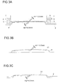
Fig. 3A is a schematic diagram for illustrating how a liquid crystal module and a convex-curved press rib are in contact with each other; -
Fig. 3B is a schematic diagram for illustrating a convex-curved press rib; and -
Fig. 3C is a schematic diagram for illustrating an open window portion of a front cabinet. - Hereinafter, embodiments of the present invention will be described with reference to the drawings. The same components will be identified by common reference signs, and detailed description of them will be omitted if possible.
- The
display apparatus 1 of this embodiment is a display apparatus using a liquid crystal panel, and is provided with, as shown inFig. 1 , afront cabinet 2 and aliquid crystal module 3 that forms a display screen by exposing aliquid crystal panel 31 through an open window portion of thefront cabinet 2. In addition, a rear cabinet (not shown) is fitted to the rear side of thefront cabinet 2. Th at is, thedisplay apparatus 1 has a cabinet structure provided with theliquid crystal module 3 provided with theliquid crystal panel 31, afront cabinet 2 provided with an open window portion through which the display screen of theliquid crystal panel 31 is exposed, and a rear cabinet that is united with thefront cabinet 2 to form the cabinet main body in which theliquid crystal module 3 is accommodated. - The
liquid crystal module 3 is built as a unit provided with, in addition to theliquid crystal panel 31, a drive circuit for driving theliquid crystal panel 31, a tuner for receiving a broadcast signal, a circuit board on which, for example, a control circuit for controlling various portions is mounted, and the like. Furtherm ore, a bezel is provided along an outer circumferential edge of theliquid crystal panel 31, and a press rib that is in contact with the bezel is provided in four sides of thefront cabinet 2 surrounding the open window portion of thefront cabinet 2. A description will be given of this cabinet structure with reference toFigs 2 ,3A, 3B, and 3C . -
Fig. 2 is a sectional view taken along line II-II ofFig. 1 , showing that thefront cabinet 2 and theliquid crystal module 3 are fixed to each other in a state in which thepress rib 4 provided in the four sides surrounding the open window portion of thefront cabinet 2 is in contact with thebezel 32 provided along the outer circumferential edge of theliquid crystal panel 31. - The cabinet structure of this embodiment is one for a display apparatus that helps achieve a preferable appearance of the
liquid crystal panel 31 and the cabinet when they are assembled together, and that even helps prevent occurrence of vibration noise. Thepress rib 4 is formed as a convex-curved press rib whosecontact portion 41 at which thepress rib 4 is in contact with thebezel 32 is curved along the length direction of the convex-curved press rib to be convex. - The
liquid crystal module 3 may be fitted to the cabinet main body by using an engagement method or by using a screw-fixing method as will be described later, as long as theliquid crystal module 3 is fixed to the cabinet main body in a state in which thebezel 32 is pressed against the convex-curved press rib 4 provided in thefront cabinet 2. How ever, the screw-fixing method is preferable because it facilitates the fitting operation, and also because the fastening force can be adjusted by using a washer or a spacer having a proper thickness. - The
press rib 4 is curved along the length direction thereof to be convex (seeFigs. 3A and 3B ), and the convex-curved portion is pressed against thebezel 32. Thus, thebezel 32 formed in a straight-line manner in theliquid crystal module 3 and thepress rib 4 are in contact with each other not in a straight line-straight line contact manner but in a straight line-curved line contact manner. As a result, the middle portion of thepress rib 4 in the length direction thereof can be securely pressed against thebezel 32. The convex-curved portion here is preferably curved to a degree that does not cause strain in the display screen of theliquid crystal panel 31, and in this embodiment, the convex-curved portion is convex such that a convex height H1 is on the order of 0.5 mm with respect to a 22-inch liquid crystal panel. With this structure, no distortion or no strain occurs in the display screen of theliquid crystal panel 31 even if the middle portion of the convex-curved press rib 4 in the length direction thereof is strongly pressed against thebezel 32, and this results in a cabinet structure for the liquid crystal module that is free from vibration noise. - As described above, by curving the convex-
curved press rib 4 to a degree that does not cause strain in the display screen of the liquid crystal panel 31 (with H1 not greater than 1 mm, preferably on the order of 0.5 mm), it is possible to prevent strain from occurring in the display screen even if the middle portion of the convex-curved press rib 4 in the length direction thereof is strongly pressed against thebezel 32, and this helps obtain a cabinet structure for a liquid crystal panel that is free from vibration noise. - It is preferable that the convex-
curved press rib 4 be curved such that the convex height H1 is not greater than 1 mm, and with respect to a large-screened liquid crystal panel, since large warp or large strain occurs in thefront cabinet 2 that is a resin product, it is preferable that the convex-curved press rib 4 be curved such that the convex height H1 is a little large; for example, the convex height H1 is preferably on the order of 0.8 mm for a 32-inch liquid crystal panel. - Also, in the above structure, it is preferable that the
contact portion 21 of the open window portion of thefront cabinet 2 at which thefront cabinet 2 is in contact with theliquid crystal panel 31 be formed as a curved window portion that is curved to the same degree as the convex-curved press rib 4. With this structure, a circumferential surface of thecontact portion 21 of thefront cabinet 2 and a circumferential surface of thecontact portion 41 of thepress rib 4 are parallel to each other. Thus, the gap between the open window portion and the liquid crystal panel is uniform, and this leads to a cabinet structure for a liquid crystal panel having a preferable appearance. To achieve this, for example, in a case in which the convex height H1 of thecontact portion 41 of thepress rib 4 is 0.5 mm, a convex height H2 of thecontact portion 21 is also set to be on the order of 0.5 mm, such that the circumferential surface of thecontact portion 21 of thefront cabinet 2 and the circumferential surface of thecontact portion 41 of thepress rib 4 are substantially parallel to each other. - Furthermore, in the above structure, it is preferable that the
contact portion 41 of the convex-curved press rib 4 be tapered toward an end thereof. With this structure, the taperedcontact portion 41 is pressed against thebezel 32 in a line-contact manner, and thus thepress rib 4 can be easily brought into a close contact with theliquid crystal module 3. This makes it possible, even with the convex-curved press rib, to bring the liquid crystal panel into a close, gapless contact with thepress rib 4 in the length direction of thepress rib 4. - The
liquid crystal module 3 can be fixed to thefront cabinet 2 via a fitting member provided on a side of theliquid crystal module 3. In this embodiment, a plurality of fitting members are provided protruding from sides of theliquid crystal module 3, and these protruding fitting members are fixed, with screws, to fitting bosses provided in thefront cabinet 2. This structure will be described with reference toFigs. 3A, 3B, and 3C . - As shown in
Fig. 3A , a plurality offitting bosses 5 for fitting theliquid crystal module 3 are provided in the four sides of thefront cabinet 2 surrounding the open window portion to be located outside thepress rib 4. In thefitting bosses 5, screw holes into which screws 7 are to be screwed are formed, and thefitting members 6 protruding from the sides of theliquid crystal module 3 are fixed to thefitting bosses 5 with thescrews 7. - It is preferable that the
fitting boss 5 be provided in plurality at predetermined intervals on a rear surface of thefront cabinet 2; for example, at four positions in four corners in the four sides of thefront cabinet 2 surrounding the open window portion. Or, as shown inFig. 1 , two positions in the middle of the longer sides of thefront cabinet 2 may be added to the four positions in the four corners such that thefitting bosses 5 are provided at six positions. - Also, the
fitting bosses 5 are fixed to thefitting members 6, with the convex-curved press rib 4 pressed against thebezel 32, by strongly pressing the middle portion of the convex-curved press rib 4 in the length direction thereof and screwingscrews 7 engaged in thefitting members 6 into screw holes formed in thefitting bosses 5. - Since the
front cabinet 2 and theliquid crystal module 3 are fixed to each other with screws at least at the four corners in the four sides via thefitting bosses 5 and thefitting members 6, the four corners of theliquid crystal module 3 can be fixed without rattle. Also, since thepress rib 4 is formed as the convex-curved press rib whose middle portion in the length direction protrudes (for example, such that the convex height H1 is 0.5 mm as shown inFig. 3B ), the middle portion of thepress rib 4 first comes in contact with theliquid crystal module 3, and a structure is realized in which a gap is less likely to occur. - Thus, even when the four corners are fixed with screws, the fixation is achieved with the middle portion of the
press rib 4 in the length direction thereof pressed against theliquid crystal module 3, and this results in a structure in which vibration noise is less likely to occur even if vibration is applied to theliquid crystal module 3. Furt hermore, when the six positions including the four positions in the four corners and the two positions in the middle portions of the longer sides are fixed with screws, even if the liquid crystal panel is a large-sized horizontally-long one, since the two middle portions are securely fixed, it is possible to effectively prevent vibration noise from occurring where thefront cabinet 2 and theliquid crystal module 3 are in contact with each other. - Also, since the
press rib 4 is formed as the convex-curved press rib whose middle portion in the length direction protrudes, even if deformation such as warp occurs in the cabinet which is made of resin, a gap is less likely to occur at the middle portion of a fitting portion at which theliquid crystal module 3 and thefront cabinet 2 are fitted to each other. Here, as shown inFig. 3C , by forming thecontact portion 21, at which the open window portion of thefront cabinet 2 is in contact with theliquid crystal panel 31, as a curved window portion that is curved to the same degree as thecontact portion 41 of thepress rib 4, that is, with the convex height H2 set to 0.5 mm, the gap between the open window portion and theliquid crystal panel 31 can be made uniform. This results in a preferable appearance. Thus, even with a liquid crystal panel having a large screen size, a cabinet structure can be obtained that is capable of realizing a preferable appearance after assembly and that is also capable of preventing vibration noise, by using a simple structure in which the contact portion with respect to theliquid crystal module 3 is formed in a convex-curved shape. - As described above, with the cabinet structure according to the present invention, the liquid crystal module is fitted to the front cabinet in a state in which the convex-curved press rib that is curved along the length direction to be convex is pressed against the bezel of the liquid crystal module. This makes it possible to fix the flat liquid crystal panel to the front cabinet with the middle portion of the convex-curved press rib in the length direction thereof strongly pressed against the bezel. Thus, the middle portion of the convex-curved press rib is pressed against the bezel, allowing no gap to occur at the fitting portion where the liquid crystal module and the front cabinet are fitted to each other. This helps achieve a structure where vibration noise is less likely to occur. Furthermore, since the gap between the liquid crystal panel and the open window portion of the front cabinet can be made uniform, a preferable appearance can be achieved. Thus, even with a liquid crystal panel having a large screen size, a cabinet structure can be obtained that is capable of realizing a preferable assembly appearance and that is also capable of preventing occurrence of vibration noise, simply by forming the press rib in a convex-curved shape.
- Furthermore, as a result of making the convex-curved press rib curve to a degree that does not cause strain in the display screen of the liquid crystal panel and making the contact portion of the open window portion at which it is in contact with the liquid crystal panel curve to the same degree as the convex-curved press rib, no strain occurs in the display screen even when the middle portion of the press rib is strongly pressed against the bezel, which leads to a vibration-noise-free cabinet structure, and moreover, the gap between the open window portion and the liquid crystal panel is uniform, which helps realize a cabinet structure for a liquid crystal panel having a preferable appearance.
- Thus, the cabinet structure for a display apparatus according to the present invention can be preferably applied to display apparatuses that use liquid crystal panels, which have been increasing in size. Fu rthermore, the cabinet structure, which is simple and thus can be easily put into commercial production, is preferable for production of liquid crystal display apparatuses, for which a large demand exists.
-
- 1
- display apparatus
- 2
- front cabinet
- 21
- contact portion
- 3
- liquid crystal module
- 31
- liquid crystal panel
- 32
- bezel
- 4
- press rib (convex-curved press rib)
- 41
- contact portion
- 5
- fitting boss
- 6
- fitting member
- H1
- convex height (contact portion 41)
- H2
- convex height (contact portion 21)
Claims (5)
- A cabinet structure for a display apparatus, comprising:a liquid crystal module provided with a liquid crystal panel;a front cabinet provided with an open window portion through which a display screen of the liquid crystal panel is exposed; anda rear cabinet that is joined to the front cabinet to form a cabinet main body in which the liquid crystal module is accommodated,characterized in
that a press rib is provided in four sides of the front cabinet surrounding the open window portion of the front cabinet so as to be in contact with a bezel provided along an outer circumferential edge of the liquid crystal panel,
that the liquid crystal module is fitted, with the press rib pressed against the bezel, and
that the press rib is formed as a convex-curved press rib in which a contact portion at which the convex-curved press rib is in contact with the bezel is curved along a length direction of the convex-curved press rib to be convex. - The cabinet structure for a display apparatus according to claim 1, further comprising:a plurality of fitting bosses provided at predetermined intervals outside the press rib on a rear surface of the front cabinet; anda fitting member provided on a side of the liquid crystal module to protrude therefrom to be engaged with the fitting bosses,wherein
the liquid crystal module is fixed to the front cabinet by fixing the fitting member to the fitting bosses by screwing screws engaged in the fitting member into screw holes formed in the fitting bosses, with the convex-curved press rib pressed against the bezel by strongly pressing a middle portion of the convex-curved press rib in a length direction thereof. - The cabinet structure for a display apparatus according to claim 1 or 2,
wherein the convex-curved press rib is curved to a degree that does not cause strain in the display screen of the liquid crystal panel. - The cabinet structure for a display apparatus according to any one of claims 1 to 3,
wherein a contact portion of the open window portion at which the open window portion is in contact with the liquid crystal panel is formed as a curved window portion that is curved to a same degree as the convex-curved press rib. - The cabinet structure for a display apparatus according to any one of claims 1 to 4,
wherein a contact portion of the convex-curved press rib is tapered toward an end thereof.
Applications Claiming Priority (1)
| Application Number | Priority Date | Filing Date | Title |
|---|---|---|---|
| JP2009025602A JP2010181665A (en) | 2009-02-06 | 2009-02-06 | Cabinet structure for display apparatus |
Publications (3)
| Publication Number | Publication Date |
|---|---|
| EP2216990A2 true EP2216990A2 (en) | 2010-08-11 |
| EP2216990A3 EP2216990A3 (en) | 2011-07-27 |
| EP2216990B1 EP2216990B1 (en) | 2013-05-15 |
Family
ID=42124288
Family Applications (1)
| Application Number | Title | Priority Date | Filing Date |
|---|---|---|---|
| EP10152414.8A Not-in-force EP2216990B1 (en) | 2009-02-06 | 2010-02-02 | Cabinet structure for display apparatus |
Country Status (3)
| Country | Link |
|---|---|
| US (1) | US8294845B2 (en) |
| EP (1) | EP2216990B1 (en) |
| JP (1) | JP2010181665A (en) |
Families Citing this family (1)
| Publication number | Priority date | Publication date | Assignee | Title |
|---|---|---|---|---|
| US9913015B2 (en) | 2013-06-20 | 2018-03-06 | Rain Case, LLC | Enclosure device for a video display |
Citations (2)
| Publication number | Priority date | Publication date | Assignee | Title |
|---|---|---|---|---|
| JP2007293129A (en) | 2006-04-26 | 2007-11-08 | Sharp Corp | Cabinet structure of display device |
| JP2008309890A (en) | 2007-06-12 | 2008-12-25 | Funai Electric Co Ltd | Thin display |
Family Cites Families (5)
| Publication number | Priority date | Publication date | Assignee | Title |
|---|---|---|---|---|
| JPH0973071A (en) * | 1995-07-03 | 1997-03-18 | Denso Corp | Liquid crystal device |
| US7529082B2 (en) * | 2004-04-16 | 2009-05-05 | Funai Electric Co., Ltd. | Plasma television, flat panel display fixing structure, flat panel television, and method of assembling flat panel television |
| JP2005345855A (en) * | 2004-06-04 | 2005-12-15 | Pioneer Electronic Corp | Display device and plasma display device |
| KR100815612B1 (en) * | 2006-12-04 | 2008-03-21 | 서상일 | TV's waterproof structure |
| JP4893302B2 (en) * | 2006-12-28 | 2012-03-07 | 船井電機株式会社 | Panel type television and display panel mounting structure |
-
2009
- 2009-02-06 JP JP2009025602A patent/JP2010181665A/en active Pending
-
2010
- 2010-02-02 EP EP10152414.8A patent/EP2216990B1/en not_active Not-in-force
- 2010-02-04 US US12/700,364 patent/US8294845B2/en not_active Expired - Fee Related
Patent Citations (2)
| Publication number | Priority date | Publication date | Assignee | Title |
|---|---|---|---|---|
| JP2007293129A (en) | 2006-04-26 | 2007-11-08 | Sharp Corp | Cabinet structure of display device |
| JP2008309890A (en) | 2007-06-12 | 2008-12-25 | Funai Electric Co Ltd | Thin display |
Also Published As
| Publication number | Publication date |
|---|---|
| EP2216990B1 (en) | 2013-05-15 |
| US8294845B2 (en) | 2012-10-23 |
| US20100201905A1 (en) | 2010-08-12 |
| JP2010181665A (en) | 2010-08-19 |
| EP2216990A3 (en) | 2011-07-27 |
Similar Documents
| Publication | Publication Date | Title |
|---|---|---|
| JP5201964B2 (en) | Image display device | |
| JP5245418B2 (en) | Thin display device | |
| US8594360B2 (en) | Mounting structure for speaker and flat panel display | |
| JP2008242334A (en) | Liquid crystal module and liquid crystal display device including the liquid crystal module | |
| EP1940162A2 (en) | Panel type TV and display panel fitting structure | |
| US7658456B2 (en) | Television and rib structure | |
| US20160309598A1 (en) | Display apparatus | |
| JP4525723B2 (en) | Thin monitor device shield structure | |
| JP2006235425A (en) | Thin display device and method of assembling thin display device | |
| EP2216990B1 (en) | Cabinet structure for display apparatus | |
| JP2009159084A (en) | Display device | |
| JP6061711B2 (en) | Display device | |
| JP2010072366A (en) | Display device | |
| JP4823370B2 (en) | Electronics | |
| JP4304515B2 (en) | Assembly structure, assembly method, and plasma television | |
| JP3115175U (en) | Liquid crystal television and display device housing structure | |
| JP5573796B2 (en) | Display panel decoration panel mounting structure | |
| KR101810990B1 (en) | Manufacturing method of an edge frame insert press for a display panel | |
| JP2011035577A (en) | Speaker device and speaker installation structure | |
| EP2581783B1 (en) | Display | |
| JP6409913B2 (en) | Display device | |
| JP2005208384A (en) | Liquid crystal display | |
| CN222169867U (en) | Drawer type television frame mounting structure | |
| JP2012253094A (en) | Electronic apparatus | |
| WO2018235770A1 (en) | Display device and television receiver |
Legal Events
| Date | Code | Title | Description |
|---|---|---|---|
| PUAI | Public reference made under article 153(3) epc to a published international application that has entered the european phase |
Free format text: ORIGINAL CODE: 0009012 |
|
| AK | Designated contracting states |
Kind code of ref document: A2 Designated state(s): AT BE BG CH CY CZ DE DK EE ES FI FR GB GR HR HU IE IS IT LI LT LU LV MC MK MT NL NO PL PT RO SE SI SK SM TR |
|
| AX | Request for extension of the european patent |
Extension state: AL BA RS |
|
| PUAL | Search report despatched |
Free format text: ORIGINAL CODE: 0009013 |
|
| AK | Designated contracting states |
Kind code of ref document: A3 Designated state(s): AT BE BG CH CY CZ DE DK EE ES FI FR GB GR HR HU IE IS IT LI LT LU LV MC MK MT NL NO PL PT RO SE SI SK SM TR |
|
| AX | Request for extension of the european patent |
Extension state: AL BA RS |
|
| 17P | Request for examination filed |
Effective date: 20120120 |
|
| 17Q | First examination report despatched |
Effective date: 20120228 |
|
| GRAP | Despatch of communication of intention to grant a patent |
Free format text: ORIGINAL CODE: EPIDOSNIGR1 |
|
| GRAS | Grant fee paid |
Free format text: ORIGINAL CODE: EPIDOSNIGR3 |
|
| GRAA | (expected) grant |
Free format text: ORIGINAL CODE: 0009210 |
|
| AK | Designated contracting states |
Kind code of ref document: B1 Designated state(s): AT BE BG CH CY CZ DE DK EE ES FI FR GB GR HR HU IE IS IT LI LT LU LV MC MK MT NL NO PL PT RO SE SI SK SM TR |
|
| REG | Reference to a national code |
Ref country code: GB Ref legal event code: FG4D Ref country code: CH Ref legal event code: EP |
|
| REG | Reference to a national code |
Ref country code: AT Ref legal event code: REF Ref document number: 612620 Country of ref document: AT Kind code of ref document: T Effective date: 20130615 |
|
| REG | Reference to a national code |
Ref country code: IE Ref legal event code: FG4D |
|
| REG | Reference to a national code |
Ref country code: DE Ref legal event code: R096 Ref document number: 602010007022 Country of ref document: DE Effective date: 20130711 |
|
| REG | Reference to a national code |
Ref country code: AT Ref legal event code: MK05 Ref document number: 612620 Country of ref document: AT Kind code of ref document: T Effective date: 20130515 |
|
| REG | Reference to a national code |
Ref country code: LT Ref legal event code: MG4D |
|
| REG | Reference to a national code |
Ref country code: NL Ref legal event code: VDEP Effective date: 20130515 |
|
| PG25 | Lapsed in a contracting state [announced via postgrant information from national office to epo] |
Ref country code: AT Free format text: LAPSE BECAUSE OF FAILURE TO SUBMIT A TRANSLATION OF THE DESCRIPTION OR TO PAY THE FEE WITHIN THE PRESCRIBED TIME-LIMIT Effective date: 20130515 Ref country code: LT Free format text: LAPSE BECAUSE OF FAILURE TO SUBMIT A TRANSLATION OF THE DESCRIPTION OR TO PAY THE FEE WITHIN THE PRESCRIBED TIME-LIMIT Effective date: 20130515 Ref country code: NO Free format text: LAPSE BECAUSE OF FAILURE TO SUBMIT A TRANSLATION OF THE DESCRIPTION OR TO PAY THE FEE WITHIN THE PRESCRIBED TIME-LIMIT Effective date: 20130815 Ref country code: ES Free format text: LAPSE BECAUSE OF FAILURE TO SUBMIT A TRANSLATION OF THE DESCRIPTION OR TO PAY THE FEE WITHIN THE PRESCRIBED TIME-LIMIT Effective date: 20130826 Ref country code: SE Free format text: LAPSE BECAUSE OF FAILURE TO SUBMIT A TRANSLATION OF THE DESCRIPTION OR TO PAY THE FEE WITHIN THE PRESCRIBED TIME-LIMIT Effective date: 20130515 Ref country code: IS Free format text: LAPSE BECAUSE OF FAILURE TO SUBMIT A TRANSLATION OF THE DESCRIPTION OR TO PAY THE FEE WITHIN THE PRESCRIBED TIME-LIMIT Effective date: 20130915 Ref country code: PT Free format text: LAPSE BECAUSE OF FAILURE TO SUBMIT A TRANSLATION OF THE DESCRIPTION OR TO PAY THE FEE WITHIN THE PRESCRIBED TIME-LIMIT Effective date: 20130916 Ref country code: SI Free format text: LAPSE BECAUSE OF FAILURE TO SUBMIT A TRANSLATION OF THE DESCRIPTION OR TO PAY THE FEE WITHIN THE PRESCRIBED TIME-LIMIT Effective date: 20130515 Ref country code: GR Free format text: LAPSE BECAUSE OF FAILURE TO SUBMIT A TRANSLATION OF THE DESCRIPTION OR TO PAY THE FEE WITHIN THE PRESCRIBED TIME-LIMIT Effective date: 20130816 Ref country code: FI Free format text: LAPSE BECAUSE OF FAILURE TO SUBMIT A TRANSLATION OF THE DESCRIPTION OR TO PAY THE FEE WITHIN THE PRESCRIBED TIME-LIMIT Effective date: 20130515 |
|
| PG25 | Lapsed in a contracting state [announced via postgrant information from national office to epo] |
Ref country code: BG Free format text: LAPSE BECAUSE OF FAILURE TO SUBMIT A TRANSLATION OF THE DESCRIPTION OR TO PAY THE FEE WITHIN THE PRESCRIBED TIME-LIMIT Effective date: 20130815 Ref country code: PL Free format text: LAPSE BECAUSE OF FAILURE TO SUBMIT A TRANSLATION OF THE DESCRIPTION OR TO PAY THE FEE WITHIN THE PRESCRIBED TIME-LIMIT Effective date: 20130515 Ref country code: HR Free format text: LAPSE BECAUSE OF FAILURE TO SUBMIT A TRANSLATION OF THE DESCRIPTION OR TO PAY THE FEE WITHIN THE PRESCRIBED TIME-LIMIT Effective date: 20130515 |
|
| PG25 | Lapsed in a contracting state [announced via postgrant information from national office to epo] |
Ref country code: LV Free format text: LAPSE BECAUSE OF FAILURE TO SUBMIT A TRANSLATION OF THE DESCRIPTION OR TO PAY THE FEE WITHIN THE PRESCRIBED TIME-LIMIT Effective date: 20130515 |
|
| PG25 | Lapsed in a contracting state [announced via postgrant information from national office to epo] |
Ref country code: SK Free format text: LAPSE BECAUSE OF FAILURE TO SUBMIT A TRANSLATION OF THE DESCRIPTION OR TO PAY THE FEE WITHIN THE PRESCRIBED TIME-LIMIT Effective date: 20130515 Ref country code: CZ Free format text: LAPSE BECAUSE OF FAILURE TO SUBMIT A TRANSLATION OF THE DESCRIPTION OR TO PAY THE FEE WITHIN THE PRESCRIBED TIME-LIMIT Effective date: 20130515 Ref country code: DK Free format text: LAPSE BECAUSE OF FAILURE TO SUBMIT A TRANSLATION OF THE DESCRIPTION OR TO PAY THE FEE WITHIN THE PRESCRIBED TIME-LIMIT Effective date: 20130515 Ref country code: EE Free format text: LAPSE BECAUSE OF FAILURE TO SUBMIT A TRANSLATION OF THE DESCRIPTION OR TO PAY THE FEE WITHIN THE PRESCRIBED TIME-LIMIT Effective date: 20130515 Ref country code: BE Free format text: LAPSE BECAUSE OF FAILURE TO SUBMIT A TRANSLATION OF THE DESCRIPTION OR TO PAY THE FEE WITHIN THE PRESCRIBED TIME-LIMIT Effective date: 20130515 |
|
| PG25 | Lapsed in a contracting state [announced via postgrant information from national office to epo] |
Ref country code: IT Free format text: LAPSE BECAUSE OF FAILURE TO SUBMIT A TRANSLATION OF THE DESCRIPTION OR TO PAY THE FEE WITHIN THE PRESCRIBED TIME-LIMIT Effective date: 20130515 Ref country code: NL Free format text: LAPSE BECAUSE OF FAILURE TO SUBMIT A TRANSLATION OF THE DESCRIPTION OR TO PAY THE FEE WITHIN THE PRESCRIBED TIME-LIMIT Effective date: 20130515 Ref country code: RO Free format text: LAPSE BECAUSE OF FAILURE TO SUBMIT A TRANSLATION OF THE DESCRIPTION OR TO PAY THE FEE WITHIN THE PRESCRIBED TIME-LIMIT Effective date: 20130515 |
|
| PLBE | No opposition filed within time limit |
Free format text: ORIGINAL CODE: 0009261 |
|
| STAA | Information on the status of an ep patent application or granted ep patent |
Free format text: STATUS: NO OPPOSITION FILED WITHIN TIME LIMIT |
|
| 26N | No opposition filed |
Effective date: 20140218 |
|
| REG | Reference to a national code |
Ref country code: DE Ref legal event code: R097 Ref document number: 602010007022 Country of ref document: DE Effective date: 20140218 |
|
| PG25 | Lapsed in a contracting state [announced via postgrant information from national office to epo] |
Ref country code: LU Free format text: LAPSE BECAUSE OF FAILURE TO SUBMIT A TRANSLATION OF THE DESCRIPTION OR TO PAY THE FEE WITHIN THE PRESCRIBED TIME-LIMIT Effective date: 20140202 Ref country code: MC Free format text: LAPSE BECAUSE OF FAILURE TO SUBMIT A TRANSLATION OF THE DESCRIPTION OR TO PAY THE FEE WITHIN THE PRESCRIBED TIME-LIMIT Effective date: 20130515 |
|
| REG | Reference to a national code |
Ref country code: CH Ref legal event code: PL |
|
| PG25 | Lapsed in a contracting state [announced via postgrant information from national office to epo] |
Ref country code: LI Free format text: LAPSE BECAUSE OF NON-PAYMENT OF DUE FEES Effective date: 20140228 Ref country code: CH Free format text: LAPSE BECAUSE OF NON-PAYMENT OF DUE FEES Effective date: 20140228 |
|
| REG | Reference to a national code |
Ref country code: IE Ref legal event code: MM4A |
|
| PG25 | Lapsed in a contracting state [announced via postgrant information from national office to epo] |
Ref country code: IE Free format text: LAPSE BECAUSE OF NON-PAYMENT OF DUE FEES Effective date: 20140202 |
|
| REG | Reference to a national code |
Ref country code: FR Ref legal event code: PLFP Year of fee payment: 7 |
|
| PG25 | Lapsed in a contracting state [announced via postgrant information from national office to epo] |
Ref country code: MT Free format text: LAPSE BECAUSE OF FAILURE TO SUBMIT A TRANSLATION OF THE DESCRIPTION OR TO PAY THE FEE WITHIN THE PRESCRIBED TIME-LIMIT Effective date: 20130515 |
|
| PG25 | Lapsed in a contracting state [announced via postgrant information from national office to epo] |
Ref country code: SM Free format text: LAPSE BECAUSE OF FAILURE TO SUBMIT A TRANSLATION OF THE DESCRIPTION OR TO PAY THE FEE WITHIN THE PRESCRIBED TIME-LIMIT Effective date: 20130515 |
|
| PGFP | Annual fee paid to national office [announced via postgrant information from national office to epo] |
Ref country code: DE Payment date: 20160127 Year of fee payment: 7 |
|
| PGFP | Annual fee paid to national office [announced via postgrant information from national office to epo] |
Ref country code: FR Payment date: 20160108 Year of fee payment: 7 Ref country code: GB Payment date: 20160127 Year of fee payment: 7 |
|
| PG25 | Lapsed in a contracting state [announced via postgrant information from national office to epo] |
Ref country code: CY Free format text: LAPSE BECAUSE OF FAILURE TO SUBMIT A TRANSLATION OF THE DESCRIPTION OR TO PAY THE FEE WITHIN THE PRESCRIBED TIME-LIMIT Effective date: 20130515 |
|
| PG25 | Lapsed in a contracting state [announced via postgrant information from national office to epo] |
Ref country code: HU Free format text: LAPSE BECAUSE OF FAILURE TO SUBMIT A TRANSLATION OF THE DESCRIPTION OR TO PAY THE FEE WITHIN THE PRESCRIBED TIME-LIMIT; INVALID AB INITIO Effective date: 20100202 Ref country code: TR Free format text: LAPSE BECAUSE OF FAILURE TO SUBMIT A TRANSLATION OF THE DESCRIPTION OR TO PAY THE FEE WITHIN THE PRESCRIBED TIME-LIMIT Effective date: 20130515 |
|
| REG | Reference to a national code |
Ref country code: DE Ref legal event code: R119 Ref document number: 602010007022 Country of ref document: DE |
|
| GBPC | Gb: european patent ceased through non-payment of renewal fee |
Effective date: 20170202 |
|
| REG | Reference to a national code |
Ref country code: FR Ref legal event code: ST Effective date: 20171031 |
|
| PG25 | Lapsed in a contracting state [announced via postgrant information from national office to epo] |
Ref country code: FR Free format text: LAPSE BECAUSE OF NON-PAYMENT OF DUE FEES Effective date: 20170228 Ref country code: DE Free format text: LAPSE BECAUSE OF NON-PAYMENT OF DUE FEES Effective date: 20170901 |
|
| PG25 | Lapsed in a contracting state [announced via postgrant information from national office to epo] |
Ref country code: GB Free format text: LAPSE BECAUSE OF NON-PAYMENT OF DUE FEES Effective date: 20170202 |
|
| PG25 | Lapsed in a contracting state [announced via postgrant information from national office to epo] |
Ref country code: MK Free format text: LAPSE BECAUSE OF FAILURE TO SUBMIT A TRANSLATION OF THE DESCRIPTION OR TO PAY THE FEE WITHIN THE PRESCRIBED TIME-LIMIT Effective date: 20130515 |