EP2216918A2 - Method and arrangement for noise variance and sir estimation - Google Patents
Method and arrangement for noise variance and sir estimation Download PDFInfo
- Publication number
- EP2216918A2 EP2216918A2 EP10164117A EP10164117A EP2216918A2 EP 2216918 A2 EP2216918 A2 EP 2216918A2 EP 10164117 A EP10164117 A EP 10164117A EP 10164117 A EP10164117 A EP 10164117A EP 2216918 A2 EP2216918 A2 EP 2216918A2
- Authority
- EP
- European Patent Office
- Prior art keywords
- noise variance
- signal
- detector
- sir
- producing
- Prior art date
- Legal status (The legal status is an assumption and is not a legal conclusion. Google has not performed a legal analysis and makes no representation as to the accuracy of the status listed.)
- Withdrawn
Links
Images


Classifications
-
- H—ELECTRICITY
- H04—ELECTRIC COMMUNICATION TECHNIQUE
- H04B—TRANSMISSION
- H04B17/00—Monitoring; Testing
- H04B17/30—Monitoring; Testing of propagation channels
- H04B17/309—Measuring or estimating channel quality parameters
- H04B17/336—Signal-to-interference ratio [SIR] or carrier-to-interference ratio [CIR]
-
- H—ELECTRICITY
- H04—ELECTRIC COMMUNICATION TECHNIQUE
- H04B—TRANSMISSION
- H04B1/00—Details of transmission systems, not covered by a single one of groups H04B3/00 - H04B13/00; Details of transmission systems not characterised by the medium used for transmission
- H04B1/69—Spread spectrum techniques
- H04B1/707—Spread spectrum techniques using direct sequence modulation
Definitions
- This invention relates to noise variance and signal/interference ratio (SIR) estimation, and particularly though not exclusively to such estimation in wireless communication receivers.
- SIR signal/interference ratio
- BPSK Binary Phase Shift Key
- QPSK Quadrature Phase Shift Key
- the second noise variance signal is produced by applying to the first noise variance signal a function substantially equal to the detector's transfer function.
- the first noise variance signal is derived from a midamble portion of the received signal.
- an estimate of total power at the detector output is produced from the second noise variance signal and an SIR signal representative of SIR in the received signal.
- a typical, standard UTRAN system 100 is conveniently considered as comprising: a terminal/user equipment domain 110; a UMTS Terrestrial Radio Access Network domain 120; and a Core Network domain 130.
- terminal equipment (TE) 112 is connected to mobile equipment (ME) 114 via the wired or wireless R interface.
- the ME 114 is also connected to a user service identity module (USIM) 116; the ME 114 and the USIM 116 together are considered as a user equipment (UE) 118.
- the UE 118 communicates data with a Node B (base station) 122 in the radio access network domain 120 via the wireless Uu interface.
- the Node B 122 communicates with a radio network controller (RNC) 124 via the lub interface.
- RNC radio network controller
- the RNC 124 communicates with other RNC's (not shown) via the lur interface.
- the Node B 122 and the RNC 124 together form the UTRAN 126.
- the RNC 124 communicates with a serving GPRS service node (SGSN) 132 in the core network domain 130 via the lu interface.
- SGSN serving GPRS service node
- GGSN gateway GPRS support node
- HLR home location register
- the GGSN 134 communicates with public data network 138 via the Gi interface.
- the elements RNC 124, SGSN 132 and GGSN 134 are conventionally provided as discrete and separate units (on their own respective software/hardware platforms) divided across the radio access network domain 120 and the core network domain 130, as shown in the FIG. 2 .
- the RNC 124 is the UTRAN element responsible for the control and allocation of resources for numerous Node B's 122; typically 50 to 100 Node B's may be controlled by one RNC.
- the RNC also provides reliable delivery of user traffic over the air interfaces. RNC's communicate with each other via the lur interface.
- the SGSN 132 is the UMTS Core Network element responsible for Session Control and interface to the HLR.
- the SGSN keeps track of the location of an individual UE and performs security functions and access control.
- the SGSN is a large centralised controller for many RNCs.
- the GGSN 134 is the UMTS Core Network element responsible for concentrating and tunnelling user data within the core packet network to the ultimate destination (e.g., internet service provider - ISP).
- the physical layer of UTRA TDD mode provides physical channels that carry transport channels from the MAC (Medium Access Control) sub-layer of UMTS Layer 2.
- a physical channel is defined by frequency, timeslot, channelisation code, burst type, and radio frame allocation.
- UMTS Layer 2 in each time slot, three burst structures (as shown generically in FIG. 2 ) can be supported, each consisting of two data fields (210, 230), a midamble (220) and a guard period (240).
- the data fields contain the data symbols from the transport channels, after the processes of coding, multiplexing, interleaving, and modulation.
- the midamble field contains the training sequence, which is used in a number of Layer 1 algorithms, such as channel estimation.
- the guard period, GP is used to accommodate any timing inaccuracies, from propagation delays, channel dispersion, and power ramping in the transmitter.
- the different burst types and their associated field lengths in chips are given in the table below: Burst Type Data Field 1 Data Field 2 Midamble L m GP Burst Type 1 976 976 512 96 Burst Type 2 1104 1104 256 96 Burst Type 3 976 880 512 192
- T denotes transposition
- f (.) denotes the transfer function of the detector
- the vector r contains the desired symbols
- the vector z contains noise plus interference.
- E (.) is the statistical average
- ⁇ z 2 E ⁇ z n + k - 1 ⁇ Q 2 is the noise variance at the output of the detector
- 2 ) is the signal power for the k th sequence.
- the following preferred embodiments of the present invention do not suffer from such a bias term and therefore do not require a look-up table to correct for the aforementioned problem.
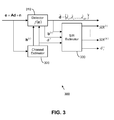
- a new technique for estimating the SIR at the output of a detector 310 uses an estimate of the detector input noise variance (derived in channel estimator 320) to provide an estimate of the detector output noise variance (derived in SIR estimator 330).
- the detector input noise variance is derived from the midamble portion of the burst using locally reconstructed replicas of the transmitted signal which are removed from the received set of samples providing a residual term that contains the noise of the channel.
- the SIR estimator 330 by deriving the transfer function of the detector an estimate of the detector output noise variance is estimated.
- the estimated output noise variance then allows an improved estimate of the SIR ( SIR (1) ... SIR ( K ) ) at the detected output.
- the SIR at the output of the detector is used for deriving soft decision quantisation levels for application to channel decoding algorithms.
- CDMA Code Division Multiple Access
- SCD single user detector
- MOD multiuser detector
- the technique described here is based on first estimating the noise variance at the input to the detector and then mapping the input noise variance to the output noise variance using the transfer function of the detector.
- the process of estimating the noise variance at the input to the detector is carried out using the midamble portion of the burst.
- e ( e 1 , e 2 ,..., e LB ) T
- L B is the burst length
- ⁇ ⁇ 2 E ⁇ e W ⁇ e W + 1 ... e X - e ⁇ W ⁇ e ⁇ W + 1 ... e ⁇ X 2
- X ⁇ L m and the starting position is W since the first W -1 samples from the midamble portion of the burst are corrupted by the data portion of the burst.
- denotes vector norm
- ⁇ 2 represents the noise variance at the input of the MUD.
- f( ⁇ 2 ) represents the noise transfer function of the detector.
- G is replaced with Q
- f ( ⁇ 2 ) is the noise transfer function of the detector.
- noise variance and SIR estimation may be carried out in software running on a processor (not shown - e.g., in User Equipment such as 118 or a Node B such as 122), and that the software may be provided as a computer program element carried on any suitable data carrier (also not shown) such as a magnetic or optical computer disc.
- noise variance and SIR estimation may alternatively be carried out in hardware, for example in the form of an integrated circuit (not shown) such as an FPGA (Field Programmable Gate Array) or ASIC (Application Specific Integrated Circuit).
- an integrated circuit not shown
- FPGA Field Programmable Gate Array
- ASIC Application Specific Integrated Circuit
Abstract
Description
- This invention relates to noise variance and signal/interference ratio (SIR) estimation, and particularly though not exclusively to such estimation in wireless communication receivers. It will be understood that, as used herein, the terms 'noise' and 'interference' are to be considered synonymous, with each encompassing both noise and interference.
- In the field of this invention it is known that many parts of a wireless communications receiver often require an estimation of noise variance and/or SIR. This is needed for purposes of power control, threshold determination for various algorithms, quantisation of soft-decision information for channel decoding purposes to name but a few.
- For BPSK (Binary Phase Shift Key) and QPSK (Quadrature Phase Shift Key) modulation the conventional method for estimating the SIR at the output of a detector relies on estimating output noise variance using the following equality known (for example) from the publication by Papoulis and Pillai, entitled 'Probability, Random Variables and Stochastic Processes', 3rd Ed. 1991,


- This yields the following result:

- However, this approach has the disadvantage(s) that the accuracy of this method at low SIR is poor since it suffers from a bias term. An analysis of the bias term and a correction method has been suggested in
GB patent application no. 0128475.1 US 2002/ 057735 A1 discloses a method for performing channel equalization in a radio receiver by determining noise power after prefiltering by estimating a noise covariance matrix. - A need therefore exists for a method and arrangement for noise variance and SIR estimation wherein the abovementioned disadvantage(s) may be alleviated.
- In accordance with embodiments of the present invention there is provided a method for noise variance estimation, a communication unit in a form of user equipment or base station, computer program product, communication system and an integrated circuit as claimed in the claims.
- In one embodiment, the second noise variance signal is produced by applying to the first noise variance signal a function substantially equal to the detector's transfer function.
- In one embodiment, the first noise variance signal is derived from a midamble portion of the received signal.
- In one embodiment, an estimate of total power at the detector output is produced from the second noise variance signal and an SIR signal representative of SIR in the received signal.
- One method and arrangement for noise variance and SIR estimation incorporating the present invention will now be described, by way of example only, with reference to the accompanying drawings, in which:
-
FIG. 1 shows a block schematic diagram illustrating a 3GPP radio communication system in which the present invention may be used; -
FIG. 2 shows a block schematic diagram illustrating a generic burst structure employed in the system ofFIG. 1 ; and -
FIG. 3 shows a block schematic diagram illustrating a detector arrangement incorporating a noise variance and SIR estimator utilising the present invention. - The following embodiment of the present invention will be described in the context of a 3GPP (3rd Generation Partnership Project) UMTS (Universal Mobile Telecommunication System) Radio Access Network (UTRAN) system operating in TDD mode. Referring firstly to
FIG. 1 , a typical, standard UTRANsystem 100 is conveniently considered as comprising: a terminal/user equipment domain 110; a UMTS Terrestrial Radio Access Networkdomain 120; and aCore Network domain 130. - In the terminal/
user equipment domain 110, terminal equipment (TE) 112 is connected to mobile equipment (ME) 114 via the wired or wireless R interface. TheME 114 is also connected to a user service identity module (USIM) 116; theME 114 and the USIM 116 together are considered as a user equipment (UE) 118. The UE 118 communicates data with a Node B (base station) 122 in the radioaccess network domain 120 via the wireless Uu interface. Within the radioaccess network domain 120, the Node B 122 communicates with a radio network controller (RNC) 124 via the lub interface. TheRNC 124 communicates with other RNC's (not shown) via the lur interface. The NodeB 122 and the RNC 124 together form the UTRAN 126. The RNC 124 communicates with a serving GPRS service node (SGSN) 132 in thecore network domain 130 via the lu interface. Within thecore network domain 130, the SGSN 132 communicates with a gateway GPRS support node (GGSN) 134 via the Gn interface; the SGSN 132 and the GGSN 134 communicate with a home location register (HLR)server 136 via the Gr interface and the Gc interface respectively. The GGSN 134 communicates withpublic data network 138 via the Gi interface. - Thus, the
elements RNC 124, SGSN 132 and GGSN 134 are conventionally provided as discrete and separate units (on their own respective software/hardware platforms) divided across the radioaccess network domain 120 and thecore network domain 130, as shown in theFIG. 2 . - The
RNC 124 is the UTRAN element responsible for the control and allocation of resources for numerous Node B's 122; typically 50 to 100 Node B's may be controlled by one RNC. The RNC also provides reliable delivery of user traffic over the air interfaces. RNC's communicate with each other via the lur interface. - The SGSN 132 is the UMTS Core Network element responsible for Session Control and interface to the HLR. The SGSN keeps track of the location of an individual UE and performs security functions and access control. The SGSN is a large centralised controller for many RNCs.
- The GGSN 134 is the UMTS Core Network element responsible for concentrating and tunnelling user data within the core packet network to the ultimate destination (e.g., internet service provider - ISP).
- Such a UTRAN system and its operation are described more fully in the 3GPP technical specification documents 3GPP TS 25.401, 3GPP TS 23.060, and related documents, available from the 3GPP website at www.3gpp.org, and need not be described in more detail herein.
- The physical layer of UTRA TDD mode provides physical channels that carry transport channels from the MAC (Medium Access Control) sub-layer of
UMTS Layer 2. A physical channel is defined by frequency, timeslot, channelisation code, burst type, and radio frame allocation. In UMTSLayer 2, in each time slot, three burst structures (as shown generically inFIG. 2 ) can be supported, each consisting of two data fields (210, 230), a midamble (220) and a guard period (240). - The data fields contain the data symbols from the transport channels, after the processes of coding, multiplexing, interleaving, and modulation. The midamble field contains the training sequence, which is used in a number of
Layer 1 algorithms, such as channel estimation. The guard period, GP, is used to accommodate any timing inaccuracies, from propagation delays, channel dispersion, and power ramping in the transmitter. The different burst types and their associated field lengths in chips are given in the table below:Burst Type Data Field 1 Data Field 2Midamble Lm GP Burst Type 1 976 976 512 96 Burst Type 21104 1104 256 96 Burst Type 3 976 880 512 192 - The received sequence in the data payload areas of the burst is given by


- The output of the detector is given by


- Expanding P (k) produces

- Under the assumption that the noise is uncorrelated with the signal vector r, the average power for the kth sequence becomes


- The conventional method for estimating the SIR relies on estimating the detector output noise variance using the following equality mentioned above:


- As discussed above, the accuracy of this approach at low SIR is poor since it suffers from a bias term, which may be corrected by use of a look-up table.
- As will be discussed in greater detail below, the following preferred embodiments of the present invention do not suffer from such a bias term and therefore do not require a look-up table to correct for the aforementioned problem.
- Referring now to
FIG. 3 , in detector arrangement 300 (which may be used inNode B 122 or User Equipment 118) a new technique for estimating the SIR at the output of adetector 310 uses an estimate of the detector input noise variance (derived in channel estimator 320) to provide an estimate of the detector output noise variance (derived in SIR estimator 330). In thechannel estimator 320 the detector input noise variance is derived from the midamble portion of the burst using locally reconstructed replicas of the transmitted signal which are removed from the received set of samples providing a residual term that contains the noise of the channel. In theSIR estimator 330, by deriving the transfer function of the detector an estimate of the detector output noise variance is estimated. - The estimated output noise variance then allows an improved estimate of the SIR (SIR (1) ... SIR (K)) at the detected output. Typically, the SIR at the output of the detector is used for deriving soft decision quantisation levels for application to channel decoding algorithms.
- In the following description, two types of CDMA (Code Division Multiple Access) detector are considered, namely single user detector (SUD) and multiuser detector (MUD). It will be understood that the invention is also applicable to other types of detector such as a RAKE receiver.
- The technique described here is based on first estimating the noise variance at the input to the detector and then mapping the input noise variance to the output noise variance using the transfer function of the detector.
- The process of estimating the noise variance at the input to the detector is carried out using the midamble portion of the burst. Considering the received sequence of chip spaced samples e = (e 1,e 2,...,eLB ) T , where LB is the burst length, a locally reconstructed version for the midamble portion of the burst is defined as follows:


- Under the assumption that the noise is white with variance σ2, the Minimum Mean Squared Error (MMSE) block linear equalizer solution to symbol estimation is given (as known from the publication of Klein, Kaleh and Baier entitled 'Zero Forcing and Minimum Mean-Square-Error Equalization for Mutliuser Detection in Code-Division Multiple-Access Channels' in IEEE Trans VT, VOL.45, No.2, May 1996, pp276-287) by


- From equation (2), the noise variance seen at the output of the MUD is given by


- Using the new estimate for the output noise variance, the SIR at the output of the MUD for the kth sequence is defined by


- It is clear from the above set of equations that when σ̂2 = σ2 we have the following

- It will therefore be understood that the accuracy of the above technique is directly related to the quality of the noise variance estimate, σ̂2, at the input of the MUD.
- For the single user detector case the received sequence is written as

- The matrix H has dimensions (NQ + W -1)×NQ and its elements are given by


- For Minimum Mean Squared Error (MMSE) symbol estimation and under the assumption that the noise is white with variance σ2, the output of the SUD is given by


- From equation (4), the noise variance seen at the output of the SUD is given by

- By replacing σ2 with the estimate of the SUD input noise variance σ̂2, we have a direct method for estimating the SUD output noise
variance 


- It is clear from the above set of equations that when σ̂2 = σ2 we have the following

- It will therefore be understood that the accuracy of the above technique is directly related to the quality of the noise variance estimate, σ̂2, at the input of the SUD.
- It will be appreciated that the method described above for noise variance and SIR estimation may be carried out in software running on a processor (not shown - e.g., in User Equipment such as 118 or a Node B such as 122), and that the software may be provided as a computer program element carried on any suitable data carrier (also not shown) such as a magnetic or optical computer disc.
- It will be also be appreciated that the arrangement described above for noise variance and SIR estimation may alternatively be carried out in hardware, for example in the form of an integrated circuit (not shown) such as an FPGA (Field Programmable Gate Array) or ASIC (Application Specific Integrated Circuit).
- It will be understood that the method and arrangement for noise variance and SIR estimation described above provides the following advantages that the accuracy of this technique is not poor at low SIR, since it does not suffer from a bias term, nor does it require correction therefor using a look-up table. An additional advantage is that any increase in estimation variance resulting from bias correction may be avoided.
Claims (15)
- A method for noise variance estimation of a detected signal, the method comprising:receiving a signal and producing therefrom in a detector (310) a detected signal; andproducing from the received signal a first noise variance signal representative of noise variance in the received signal;the method characterised by:producing from the detected signal and the first noise variance signal a second noise variance signal representative of noise variance estimation in the received signal.
- The method of claim 1 wherein the step of producing the second noise variance signal comprises applying a function equal to the detector's transfer function to the first noise variance signal.
- The method of claim 1 or claim 2 wherein the step of producing the first noise variance signal comprises deriving the first noise variance signal from a midamble portion of the received signal.
- The method of any preceding claim further comprising:producing from the second noise variance signal and an estimate of total power at the detector output a signal-to-interference ratio (SIR) signal representative of SIR in the received signal.
- The method of any preceding claim wherein the detector is or comprises at least one from a group consisting of: a CDMA multi-user detector, a CDMA single-user detector, a CDMA RAKE receiver.
- The method of any preceding claim wherein the received signal is a wireless UMTS air interface signal.
- A communication unit comprising a receiver (300) capable of noise variance estimation of a detected signal, the receiver comprising:a detector (310) for receiving a signal and detecting therein a detected signal; andfirst noise variance logic (330) for producing from the received signal a first noise variance signal representative of noise variance in the received signal;the receiver characterised by:second noise variance logic (330) for producing from the detected signal and the first noise variance signal a second noise variance signal representative of noise variance estimation in the received signal.
- The communication unit of claim 7 wherein the second noise variance logic is arranged to apply a function equal to the detector's transfer function to the first noise variance signal to produce the second noise variance signal.
- The communication unit of claim 7 or claim 8 wherein the first noise variance logic is arranged to derive the first noise variance signal from a midamble portion of the received signal.
- The communication unit of any of preceding claims 7 to 9 further comprising:signal-to-interference ratio (SIR) estimation logic for producing from the second noise variance signal and an estimate of total power at the detector output an SIR signal representative of SIR in the received signal.
- The communication unit of any of preceding claims 7 to 10 wherein the detector is or comprises at least one from a group consisting of: a CDMA multi-user detector, a CDMA single-user detector, a CDMA RAKE receiver.
- The communication unit of any of preceding claims 7 to 11 wherein the communication unit is one of: a user equipment, a base station.
- A computer program product comprising program code for noise variance estimation of a detected signal, the computer program product comprising program code for:receiving a signal and producing therefrom in a detector a detected signal; andproducing from the received signal a first noise variance signal representative of noise variance in the received signal;the program code characterised by:producing from the detected signal and the first noise variance signal a second noise variance signal representative of noise variance estimation in the received signal.
- A communication system comprising a communication unit of any of preceding claims 7 to 12 arranged to provide for noise variance estimation of a detected signal.
- An integrated circuit comprising a detector for receiving a signal and detecting therein a detected signal;
first noise variance means for producing from the received signal a first noise variance signal representative of noise variance in the received signal;
the integrated circuit characterised by:second noise variance means for producing from the detected signal and the first noise variance signal a second noise variance signal representative of noise variance estimation in the received signal.
Applications Claiming Priority (2)
| Application Number | Priority Date | Filing Date | Title |
|---|---|---|---|
| GB0318529A GB2404822B (en) | 2003-08-07 | 2003-08-07 | Method and arrangement for noise variance and sir estimation |
| EP04767979A EP1661273B1 (en) | 2003-08-07 | 2004-08-05 | Method and arrangement for noise variance and sir estimation |
Related Parent Applications (1)
| Application Number | Title | Priority Date | Filing Date |
|---|---|---|---|
| EP04767979.0 Division | 2004-08-05 |
Publications (1)
| Publication Number | Publication Date |
|---|---|
| EP2216918A2 true EP2216918A2 (en) | 2010-08-11 |
Family
ID=27839808
Family Applications (2)
| Application Number | Title | Priority Date | Filing Date |
|---|---|---|---|
| EP10164117A Withdrawn EP2216918A2 (en) | 2003-08-07 | 2004-08-05 | Method and arrangement for noise variance and sir estimation |
| EP04767979A Not-in-force EP1661273B1 (en) | 2003-08-07 | 2004-08-05 | Method and arrangement for noise variance and sir estimation |
Family Applications After (1)
| Application Number | Title | Priority Date | Filing Date |
|---|---|---|---|
| EP04767979A Not-in-force EP1661273B1 (en) | 2003-08-07 | 2004-08-05 | Method and arrangement for noise variance and sir estimation |
Country Status (7)
| Country | Link |
|---|---|
| US (1) | US7590388B2 (en) |
| EP (2) | EP2216918A2 (en) |
| AT (1) | ATE474387T1 (en) |
| DE (1) | DE602004028133D1 (en) |
| ES (1) | ES2348301T3 (en) |
| GB (1) | GB2404822B (en) |
| WO (1) | WO2005015790A1 (en) |
Families Citing this family (11)
| Publication number | Priority date | Publication date | Assignee | Title |
|---|---|---|---|---|
| US20040110508A1 (en) * | 2002-09-20 | 2004-06-10 | Jacobus Haartsen | Methods and electronic devices for wireless ad-hoc network communications using receiver determined channels and transmitted reference signals |
| GB2404822B (en) | 2003-08-07 | 2007-07-11 | Ipwireless Inc | Method and arrangement for noise variance and sir estimation |
| US7782987B2 (en) | 2004-03-12 | 2010-08-24 | Telefonaktiebolaget Lm Ericsson (Publ) | Method and apparatus for received signal quality estimation |
| US7421045B2 (en) * | 2005-03-18 | 2008-09-02 | Interdigital Technology Corporation | Method and apparatus for computing SIR of time varying signals in a wireless communication system |
| US7603092B2 (en) * | 2006-06-19 | 2009-10-13 | Motorola, Inc. | Estimation of CINR and RSSI in a wireless communication system |
| FI20075272A0 (en) * | 2007-04-19 | 2007-04-19 | Nokia Corp | Receiver and Receiving Method |
| US8767952B2 (en) * | 2007-12-17 | 2014-07-01 | Broadcom Corporation | Method and system for utilizing a single connection for efficient delivery of power and multimedia information |
| WO2009118700A1 (en) * | 2008-03-26 | 2009-10-01 | Nxp B.V. | System and method for high performance finite-sample-based noise variance estimation for td-scdma |
| US20110319045A1 (en) * | 2010-05-05 | 2011-12-29 | Wenjun Li | Linear interference cancellation receiver |
| US8554151B2 (en) * | 2010-12-03 | 2013-10-08 | Qualcomm Incorporated | Method and apparatus for data aided channel quality estimation |
| TWI607633B (en) * | 2016-01-19 | 2017-12-01 | 瑞昱半導體股份有限公司 | Noise variance estimation circuit and method for wireless communication |
Citations (1)
| Publication number | Priority date | Publication date | Assignee | Title |
|---|---|---|---|---|
| US20020057735A1 (en) | 2000-04-06 | 2002-05-16 | Olli Piirainen | Optimizing of channel equalizer |
Family Cites Families (95)
| Publication number | Priority date | Publication date | Assignee | Title |
|---|---|---|---|---|
| GB128475A (en) | 1918-09-17 | 1919-06-26 | Abraham Barraclough | Car Stopping and Holding Mechanism. |
| US5214675A (en) * | 1991-07-02 | 1993-05-25 | Motorola, Inc. | System and method for calculating channel gain and noise variance of a communication channel |
| US5278871A (en) * | 1992-03-19 | 1994-01-11 | Motorola, Inc. | Method and apparatus for estimating signal weighting parameters in a receiver |
| US5406593A (en) * | 1993-08-20 | 1995-04-11 | General Electric Company | Adaptive phase-locked loop employing channel state information estimation from received signal phase angles |
| US5351274A (en) * | 1993-08-20 | 1994-09-27 | General Electric Company | Post detection selection combining diversity receivers for mobile and indoor radio channels |
| US5343496A (en) * | 1993-09-24 | 1994-08-30 | Bell Communications Research, Inc. | Interference suppression in CDMA systems |
| JP2993554B2 (en) * | 1994-05-12 | 1999-12-20 | エヌ・ティ・ティ移動通信網株式会社 | Transmission power control method and communication device using the transmission power control method |
| FR2731571A1 (en) * | 1995-03-08 | 1996-09-13 | Philips Electronique Lab | COMMUNICATION SYSTEM EQUIPPED WITH MEANS FOR TESTING A TRANSMISSION CHANNEL AND TEST METHOD |
| US5648983A (en) * | 1995-04-24 | 1997-07-15 | Lucent Technologies Inc. | CDMA rake receiver with sub-chip resolution |
| US6181739B1 (en) * | 1995-11-22 | 2001-01-30 | Telefonaktiebolaget Lm Ericsson (Publ) | Signal-to-noise ratio determination using digital signal processing |
| US5987069A (en) * | 1996-12-24 | 1999-11-16 | Gte Government Systems Corporation | Method and apparatus for variably allocating upstream and downstream communication spectra |
| US6167039A (en) * | 1997-12-17 | 2000-12-26 | Telefonaktiebolget Lm Ericsson | Mobile station having plural antenna elements and interference suppression |
| US6078796A (en) * | 1998-01-29 | 2000-06-20 | Motorola, Inc. | Method and apparatus for receiving a wideband signal using multiple automatic gain controllers |
| US6292519B1 (en) * | 1998-03-11 | 2001-09-18 | Telefonaktiebolaget Lm Ericsson (Publ) | Correction of signal-to-interference ratio measurements |
| US6370397B1 (en) * | 1998-05-01 | 2002-04-09 | Telefonaktiebolaget Lm Ericsson (Publ) | Search window delay tracking in code division multiple access communication systems |
| US6731622B1 (en) * | 1998-05-01 | 2004-05-04 | Telefonaktiebolaget Lm Ericsson (Publ) | Multipath propagation delay determining means using periodically inserted pilot symbols |
| US6157820A (en) * | 1998-06-12 | 2000-12-05 | Ericsson Inc. | Pilot strength measurement and multipath delay searcher for CDMA receiver |
| EP0966113B1 (en) * | 1998-06-19 | 2003-12-10 | Motorola Semiconducteurs S.A. | Method and apparatus for performing equalisation in a radio receiver |
| AU1232499A (en) * | 1998-10-26 | 2000-05-15 | Nokia Corporation | Channel estimation in a cellular communication system |
| US6373878B1 (en) * | 1998-11-02 | 2002-04-16 | Telefonaktiebolaget Lm Ericsson (Publ) | Using a fast AGC as part of SIR calculation |
| JP3327227B2 (en) * | 1998-11-11 | 2002-09-24 | 三菱マテリアル株式会社 | Wireless communication system and recording medium |
| FR2789534B1 (en) * | 1999-02-04 | 2001-06-08 | Cit Alcatel | METHOD OF ESTIMATING THE SIGNAL TO NOISE RATIO OF A DIGITAL SIGNAL RECEIVED BY A RADIO COMMUNICATION RECEIVER |
| US6542562B1 (en) * | 1999-02-09 | 2003-04-01 | Telefonaktiebolaget Lm Ericsson (Publ) | Approximated MMSE-based channel estimator in a mobile communication system |
| CA2260336A1 (en) * | 1999-02-15 | 2000-08-15 | Robert Inkol | Modulation recognition system |
| US7151761B1 (en) * | 1999-03-19 | 2006-12-19 | Telefonaktiebolaget L M Ericsson (Publ) | Code reservation for interference measurement in a CDMA radiocommunication system |
| US6377607B1 (en) * | 1999-05-13 | 2002-04-23 | Qualcomm Incorporated | System and method for performing accurate demodulation of turbo-encoded signals via pilot assisted coherent demodulation |
| WO2000077946A1 (en) * | 1999-06-11 | 2000-12-21 | Nokia Corporation | Method and apparatus for performing interference estimation |
| DE69906262T2 (en) * | 1999-07-01 | 2003-12-04 | Alcatel Sa | Adaptive path finder in a CDMA receiver |
| US6891897B1 (en) * | 1999-07-23 | 2005-05-10 | Nortel Networks Limited | Space-time coding and channel estimation scheme, arrangement and method |
| US6463105B1 (en) * | 1999-09-13 | 2002-10-08 | Ericsson Inc. | Methods and systems for estimation of the carrier to interference ratio for a wireless communication channel |
| ES2160087B1 (en) * | 2000-02-18 | 2003-03-01 | Mier Comunicaciones S A | PROCEDURE FOR REPETITION OF SIGNALS IN INSOFREQUENCY AND REPEATER OF SIGNS IN ISOFREQUENCY. |
| US6600772B1 (en) * | 2000-03-21 | 2003-07-29 | Interdigital Communications Corporation | Combined closed loop/open loop power control in a time division duplex communication system |
| KR100327385B1 (en) * | 2000-07-18 | 2002-03-13 | Lg Electronics Inc | Spatio-temporal three-dimensional noise filter |
| GB2365282B (en) * | 2000-07-19 | 2004-02-11 | Ericsson Telefon Ab L M | Communications system |
| AU2001282755A1 (en) * | 2000-08-04 | 2002-02-18 | Telefonaktiebolaget Lm Ericsson (Publ) | Spreading factor detector |
| GB0031834D0 (en) * | 2000-12-29 | 2001-02-14 | Nokia Networks Oy | Parameter estimation for adaptive antenna system |
| FR2819357B1 (en) * | 2001-01-09 | 2016-02-12 | Thomson Csf | AUTODIDACTIVE METHOD AND RECEIVER FOR DETERMINING SPATIO-TEMPORAL PARAMETERS OF A PROPAGATION CHANNEL |
| US6707864B2 (en) * | 2001-01-25 | 2004-03-16 | Interdigital Technology Corporation | Simplified block linear equalizer with block space time transmit diversity |
| US6980602B1 (en) * | 2001-01-31 | 2005-12-27 | Comsys Communication & Signal Processing Ltd. | Normalization of equalizer soft output for channels with varying noise power |
| US6885654B2 (en) * | 2001-02-06 | 2005-04-26 | Interdigital Technology Corporation | Low complexity data detection using fast fourier transform of channel correlation matrix |
| US6882619B1 (en) * | 2001-02-21 | 2005-04-19 | At&T Corp. | Interference suppressing OFDM method for wireless communications |
| TWI233556B (en) * | 2001-03-26 | 2005-06-01 | Japan Science & Tech Corp | Filter apparatus, reception apparatus, transmission apparatus, diffusion modulation apparatus, pseudo-random number sequence output apparatus, filter method, reception method, transmission method |
| ATE297613T1 (en) * | 2001-04-24 | 2005-06-15 | Nokia Corp | METHOD AND DEVICE FOR ESTIMATING THE SOUND RATIO OF A SIGNAL |
| US6625203B2 (en) * | 2001-04-30 | 2003-09-23 | Interdigital Technology Corporation | Fast joint detection |
| US7453933B2 (en) * | 2001-05-04 | 2008-11-18 | Lucent Technologies Inc. | Method of estimating a signal-to-interference+noise ratio (SINR) using data samples |
| US7184497B2 (en) * | 2001-05-04 | 2007-02-27 | Lucent Technologies Inc. | Method of estimating a signal-to-interference+noise ratio (SINR) |
| US8611311B2 (en) * | 2001-06-06 | 2013-12-17 | Qualcomm Incorporated | Method and apparatus for canceling pilot interference in a wireless communication system |
| US20050013350A1 (en) * | 2001-06-06 | 2005-01-20 | Coralli Alessandro Vanelli | Method and apparatus for canceling pilot interference in a wireless communication system |
| US7228146B2 (en) * | 2001-06-26 | 2007-06-05 | Nxp B.V. | Estimating Eb/Nt in a CDMA system using power control bits |
| CN1156179C (en) * | 2001-09-03 | 2004-06-30 | 信息产业部电信传输研究所 | Dynamic regulation method and device of channel estimation everage region |
| US6816470B2 (en) * | 2001-09-18 | 2004-11-09 | Interdigital Technology Corporation | Method and apparatus for interference signal code power and noise variance estimation |
| CA2405322A1 (en) * | 2001-09-28 | 2003-03-28 | Telecommunications Research Laboratories | Channel code decoding for the cdma forward link |
| US7039135B2 (en) * | 2001-10-11 | 2006-05-02 | D.S.P.C. Technologies Ltd. | Interference reduction using low complexity antenna array |
| US7349667B2 (en) * | 2001-10-19 | 2008-03-25 | Texas Instruments Incorporated | Simplified noise estimation and/or beamforming for wireless communications |
| GB2382748A (en) * | 2001-11-28 | 2003-06-04 | Ipwireless Inc | Signal to noise plus interference ratio (SNIR) estimation with corection factor |
| US6973296B2 (en) * | 2001-12-04 | 2005-12-06 | Intersil Americas Inc. | Soft decision gain compensation for receive filter attenuation |
| CA2415170C (en) * | 2001-12-28 | 2008-07-15 | Ntt Docomo, Inc. | Receiver, transmitter, communication system, and method of communication |
| US7369523B2 (en) * | 2002-02-20 | 2008-05-06 | Texas Instruments Incorporated | Data signal demodulation in a communication system |
| US7190665B2 (en) * | 2002-04-19 | 2007-03-13 | Texas Instruments Incorporated | Blind crosstalk cancellation for multicarrier modulation |
| US6757321B2 (en) * | 2002-05-22 | 2004-06-29 | Interdigital Technology Corporation | Segment-wise channel equalization based data estimation |
| US7184713B2 (en) * | 2002-06-20 | 2007-02-27 | Qualcomm, Incorporated | Rate control for multi-channel communication systems |
| US6928104B2 (en) * | 2002-07-18 | 2005-08-09 | Interdigital Technology Corporation | Scaling using gain factors for use in data detection for wireless code division multiple access communication systems |
| US7440524B2 (en) * | 2002-08-13 | 2008-10-21 | Mediatek, Inc. | Channel estimation in a wireless transmission system |
| US7349379B2 (en) * | 2002-08-13 | 2008-03-25 | Texas Instruments Incorporated | Channel normalization |
| AU2003256426A1 (en) * | 2002-08-20 | 2004-03-11 | Interdigital Technology Corporation | Efficient joint detection |
| US7372402B2 (en) * | 2002-08-30 | 2008-05-13 | Telfonaktiebolaget Lm Ericsson (Publ) | Method for enhancing the measuring accuracy in an antenna array |
| US7408978B2 (en) * | 2002-09-09 | 2008-08-05 | Interdigital Technology Corporation | Extended algorithm data estimator |
| US7010019B2 (en) * | 2002-09-18 | 2006-03-07 | Telefonaktiebolaget Lm Ericsson (Publ) | Assessment of delay estimation quality using interference estimates |
| US7606293B2 (en) * | 2002-10-25 | 2009-10-20 | Gct Semiconductor, Inc. | Bidirectional turbo ISI canceller-based DSSS receiver for high-speed wireless LAN |
| US7277474B2 (en) * | 2002-11-05 | 2007-10-02 | Analog Devices, Inc. | Finger allocation for a path searcher in a multipath receiver |
| CN1833389B (en) * | 2002-11-22 | 2011-01-05 | 美商内数位科技公司 | Channel gain estimation in a rake receiver using complex weight generation (cwg) algorithms |
| WO2004049661A1 (en) * | 2002-11-22 | 2004-06-10 | Telefonaktiebolaget Lm Ericsson (Publ) | Calculation of soft decision values using reliability information of the amplitude |
| US20040120300A1 (en) * | 2002-12-02 | 2004-06-24 | Board Of Regents, The University Of Texas System | System, method and apparatus for parallel information transmission in wireless communication systems |
| US7286514B2 (en) * | 2002-12-10 | 2007-10-23 | New Jersey Institute Of Technology | Method for phase noise suppression for OFDM based WLANs |
| CN1723629A (en) * | 2003-01-10 | 2006-01-18 | 美商内数位科技公司 | Generalized two-stage data estimation |
| US7088978B2 (en) * | 2003-02-07 | 2006-08-08 | Ericsson Inc. | System and method for interference cancellation in a wireless communication receiver |
| US7386057B2 (en) * | 2003-02-20 | 2008-06-10 | Nec Corporation | Iterative soft interference cancellation and filtering for spectrally efficient high-speed transmission in MIMO systems |
| US7042967B2 (en) * | 2003-03-03 | 2006-05-09 | Interdigital Technology Corporation | Reduced complexity sliding window based equalizer |
| US7031284B2 (en) * | 2003-03-03 | 2006-04-18 | Interdigital Technology Corporation | Wireless communication method and apparatus for optimizing multi-user detection |
| US7200190B2 (en) * | 2003-06-30 | 2007-04-03 | Motorola, Inc. | Unbiased signal to interference ratio in wireless communications devices and methods therefor |
| US7154966B2 (en) * | 2003-06-30 | 2006-12-26 | Telefonaktiebolaget L M Ericsson (Publ) | Method and system for M-QAM detection in communication systems |
| GB2404822B (en) | 2003-08-07 | 2007-07-11 | Ipwireless Inc | Method and arrangement for noise variance and sir estimation |
| US7457379B2 (en) * | 2003-10-16 | 2008-11-25 | Broadcom Corporation | Adaptive multi-step combined DC offset compensation for EDGE 8-PSK |
| US7173973B2 (en) * | 2003-10-31 | 2007-02-06 | Nokia Corporation | Multiple-antenna partially coherent constellations for multi-carrier systems |
| US20050102600A1 (en) * | 2003-11-10 | 2005-05-12 | Anand Anandakumar | High data rate communication system for wireless applications |
| US7813457B2 (en) * | 2003-12-29 | 2010-10-12 | Intel Corporation | Device, system and method for detecting and handling co-channel interference |
| US7386030B2 (en) * | 2004-02-17 | 2008-06-10 | Texas Instruments Incorporated | Automatic threshold selection method for improving the detection of a wireless signal |
| US7782987B2 (en) * | 2004-03-12 | 2010-08-24 | Telefonaktiebolaget Lm Ericsson (Publ) | Method and apparatus for received signal quality estimation |
| US7457367B2 (en) * | 2004-07-07 | 2008-11-25 | University Of Utah Research Foundation | Detector and method for estimating data probability in a multi-channel receiver |
| US20060089559A1 (en) * | 2004-08-26 | 2006-04-27 | Riccardo Barbieri | Realtime monitoring and analysis of heart-beat dynamics |
| FR2881590B1 (en) * | 2005-01-31 | 2007-04-06 | Agence Spatiale Europeenne | METHOD FOR DIGITAL PACKET COMMUNICATION THROUGH A TRANSMISSION CHANNEL SHARED BY A PLURALITY OF USERS |
| US7580445B2 (en) * | 2005-08-22 | 2009-08-25 | Nec Laboratories America, Inc. | Nonlinear precoding in code-division multiple access communication system |
| US9071344B2 (en) * | 2005-08-22 | 2015-06-30 | Qualcomm Incorporated | Reverse link interference cancellation |
| US7474640B2 (en) * | 2005-09-28 | 2009-01-06 | Intel Corporation | System, method and device of interference mitigation in wireless communication |
| US7787892B2 (en) * | 2005-10-05 | 2010-08-31 | Via Technologies, Inc. | Method and apparatus for adaptive multi-stage multi-threshold detection of paging indicators in wireless communication systems |
-
2003
- 2003-08-07 GB GB0318529A patent/GB2404822B/en not_active Expired - Fee Related
-
2004
- 2004-08-05 WO PCT/GB2004/003368 patent/WO2005015790A1/en active Application Filing
- 2004-08-05 ES ES04767979T patent/ES2348301T3/en active Active
- 2004-08-05 AT AT04767979T patent/ATE474387T1/en not_active IP Right Cessation
- 2004-08-05 EP EP10164117A patent/EP2216918A2/en not_active Withdrawn
- 2004-08-05 EP EP04767979A patent/EP1661273B1/en not_active Not-in-force
- 2004-08-05 US US10/567,317 patent/US7590388B2/en active Active
- 2004-08-05 DE DE602004028133T patent/DE602004028133D1/en active Active
Patent Citations (1)
| Publication number | Priority date | Publication date | Assignee | Title |
|---|---|---|---|---|
| US20020057735A1 (en) | 2000-04-06 | 2002-05-16 | Olli Piirainen | Optimizing of channel equalizer |
Non-Patent Citations (1)
| Title |
|---|
| "Zero Forcing and Minimum Mean-Square-Error Equalization for Mutliuser Detection in Code-Division Multiple-Access Channels", IEEE TRANS VT, vol. 45, no. 2, May 1996 (1996-05-01), pages 276 - 287 |
Also Published As
| Publication number | Publication date |
|---|---|
| US7590388B2 (en) | 2009-09-15 |
| GB2404822A (en) | 2005-02-09 |
| ES2348301T3 (en) | 2010-12-02 |
| GB0318529D0 (en) | 2003-09-10 |
| WO2005015790A1 (en) | 2005-02-17 |
| EP1661273B1 (en) | 2010-07-14 |
| ATE474387T1 (en) | 2010-07-15 |
| US20070207741A1 (en) | 2007-09-06 |
| EP1661273A1 (en) | 2006-05-31 |
| DE602004028133D1 (en) | 2010-08-26 |
| GB2404822B (en) | 2007-07-11 |
Similar Documents
| Publication | Publication Date | Title |
|---|---|---|
| EP1332565B1 (en) | Single user detection | |
| US7920537B2 (en) | Method and arrangement for mitigation of intercell interference in a cellular communication system | |
| US7609750B2 (en) | Segment-wise channel equalization based data estimation | |
| EP1661273B1 (en) | Method and arrangement for noise variance and sir estimation | |
| CN100568746C (en) | Coding/decoding method and equipment | |
| US20060098600A1 (en) | Decreasing computational complexity of TD-SCDMA measurement process | |
| EP1513270B1 (en) | Method for estimating the Doppler spread in radio mobile telecommunication systems | |
| US20020191577A1 (en) | Iterative fast fourier transform error correction | |
| EP1428338B1 (en) | Method and apparatus for interference signal code power and noise variance estimation | |
| JP2003046412A (en) | Demodulator, demodulation method and communication device | |
| US20050047376A1 (en) | Method of determining an acquisition indicator bit in a communication system | |
| EP1156592A2 (en) | A reception method and a CDMA receiver |
Legal Events
| Date | Code | Title | Description |
|---|---|---|---|
| PUAI | Public reference made under article 153(3) epc to a published international application that has entered the european phase |
Free format text: ORIGINAL CODE: 0009012 |
|
| AC | Divisional application: reference to earlier application |
Ref document number: 1661273 Country of ref document: EP Kind code of ref document: P |
|
| AK | Designated contracting states |
Kind code of ref document: A2 Designated state(s): AT BE BG CH CY CZ DE DK EE ES FI FR GB GR HU IE IT LI LU MC NL PL PT RO SE SI SK TR |
|
| RAP1 | Party data changed (applicant data changed or rights of an application transferred) |
Owner name: WIRELESS TECHNOLOGY SOLUTIONS LLC |
|
| RAP1 | Party data changed (applicant data changed or rights of an application transferred) |
Owner name: IP WIRELESS, INC. |
|
| RAP1 | Party data changed (applicant data changed or rights of an application transferred) |
Owner name: NVIDIA CORPORATION |
|
| STAA | Information on the status of an ep patent application or granted ep patent |
Free format text: STATUS: THE APPLICATION HAS BEEN WITHDRAWN |
|
| 18W | Application withdrawn |
Effective date: 20141111 |