EP2216883A1 - Rotary machine rotor - Google Patents
Rotary machine rotor Download PDFInfo
- Publication number
- EP2216883A1 EP2216883A1 EP08855456A EP08855456A EP2216883A1 EP 2216883 A1 EP2216883 A1 EP 2216883A1 EP 08855456 A EP08855456 A EP 08855456A EP 08855456 A EP08855456 A EP 08855456A EP 2216883 A1 EP2216883 A1 EP 2216883A1
- Authority
- EP
- European Patent Office
- Prior art keywords
- rotor
- permanent magnets
- rotating electrical
- electrical machine
- blank
- Prior art date
- Legal status (The legal status is an assumption and is not a legal conclusion. Google has not performed a legal analysis and makes no representation as to the accuracy of the status listed.)
- Granted
Links
Images







Classifications
-
- H—ELECTRICITY
- H02—GENERATION; CONVERSION OR DISTRIBUTION OF ELECTRIC POWER
- H02K—DYNAMO-ELECTRIC MACHINES
- H02K1/00—Details of the magnetic circuit
- H02K1/06—Details of the magnetic circuit characterised by the shape, form or construction
- H02K1/22—Rotating parts of the magnetic circuit
- H02K1/27—Rotor cores with permanent magnets
- H02K1/2706—Inner rotors
- H02K1/272—Inner rotors the magnetisation axis of the magnets being perpendicular to the rotor axis
- H02K1/274—Inner rotors the magnetisation axis of the magnets being perpendicular to the rotor axis the rotor consisting of two or more circumferentially positioned magnets
- H02K1/2753—Inner rotors the magnetisation axis of the magnets being perpendicular to the rotor axis the rotor consisting of two or more circumferentially positioned magnets the rotor consisting of magnets or groups of magnets arranged with alternating polarity
- H02K1/276—Magnets embedded in the magnetic core, e.g. interior permanent magnets [IPM]
- H02K1/2766—Magnets embedded in the magnetic core, e.g. interior permanent magnets [IPM] having a flux concentration effect
-
- H—ELECTRICITY
- H02—GENERATION; CONVERSION OR DISTRIBUTION OF ELECTRIC POWER
- H02K—DYNAMO-ELECTRIC MACHINES
- H02K2201/00—Specific aspects not provided for in the other groups of this subclass relating to the magnetic circuits
- H02K2201/06—Magnetic cores, or permanent magnets characterised by their skew
Definitions
- the present invention relates to a rotor for a rotating electrical machine, and particularly, to a rotor for a rotating electrical machine, capable of suppressing demagnetization of permanent magnets without deteriorating motor characteristics, being highly reliable, and being manufactured at low cost.
- rotatingelectrical machines for vehicles such as hybrid cars are strongly required to suppress exhaust gas, reduce fuel consumption, and improve efficiency. They are also required to reduce installation spaces, fit in limited spaces, and provide high torque and high output. To achieve them, rotating electrical machines of high energy density that need large current and magnetomotive force are expected. Realizing such rotating electrical machines, however, involves various problems.
- a rotating electrical machine with a rotor in which permanent magnets of high magnetic energy product are embedded produces large electromagnetic exciting force to cause vibration and noise.
- a rotating electrical machine for a hybrid vehicle is particularly required to realize quietness in a cabin and reduce noise to the outside.
- Patent Document 1 describes a rotor for a reluctance-type rotating electrical machine that achieves an effect similar to a skew effect, to reduce torque ripples, vibration, and noise.
- This rotor for a reluctance-type rotating electrical machine includes a rotor core formed by laminating many annular core materials whose outer circumferential parts are provided with alternating magnetic irregularities, an inner circumferential part of the rotor core being provided with an axially extending key, and a rotary shaft inserted into the inner circumferential part of the rotor core and having a key groove on an outer circumferential part thereof.
- the rotor core is divided into a plurality of blocks.
- the core materials that form one block are structured such that the magnetic irregularities are shifted by a predetermined angle toward one of a rotation direction and counter rotation direction with respect to a center line passing through the key.
- the core materials of each adjacent block are formed such that the magnetic irregularities are shifted by a predetermined angle toward the other of the rotation direction and counter rotation direction with respect to the center line passing through the key.
- Figure 15 is a diametrical sectional view of the rotor described in the Patent Document 1.
- a pair of magnet insertion holes 5 each substantially having a rectangular shape is formed such that a distance between the holes 5 gradually extends toward an outer circumference.
- Permanent magnets 6 are inserted into the magnet insertion holes 5 and are fixed thereto with an adhesive or a filler.
- a hollow 7 is formed between the pair of permanent magnets 6.
- the hollow 7 is substantially triangular with two sides being in parallel with the pair of permanent magnets 6 and one side extending along the outer circumference.
- a section including a pair of the magnet insertion holes 5, a pair of the permanent magnets 6, and the hollow 7 is a magnetic recess (q-axis, inter-pole section) 8 where magnetic flux hardly passes and a section between adj acent magnetic recesses 8 is a magnetic projection (d-axis, pole section) 9 where magnetic flux easily passes.
- the magnetic recesses 8 and magnetic projections 9 are alternately formed at intervals of predetermined angles.
- two axially extending keys 30 and 31 are formed at intervals of 180 degrees.
- a center line Lo passing through the centers of the keys 30 and 31 passes thorough the magnetic projections 9.
- the center line Lo deviates by an angle of ⁇ from a center line Loa passing through the centers of the magnetic projections 9.
- the center line Loa is present at a position shifted from the center line Lo by the angle ⁇ in a direction (clockwise direction) opposite to a rotation direction X.
- the center line Loa and a center line Lb that is adjacent to the center line Loa and passes through the centers of the magnetic recesses 8 form a predetermined angle of ⁇ .
- Figure 16 is a partial top view of the rotor described in the Patent Document 1.
- the rotor has the rotor core formed by laminating many annular core materials such as silicon steel plates.
- the rotor core is divided into four blocks 3 and 4 having an equal thickness, the four blocks being stackedtogether.
- the blocks 3 and 4 have center lines Lb and Lc having linear loci that are zigzagged without forming a prior-art-like straight line.
- the rotor provides an effect similar to a skew effect provided by a rotor for a squirrel-cage induction motor. Deviations of the center lines Lb and Lc must be ⁇ 0 (equally shifted in "+" and "-" directions).
- the rotor is arranged in a stator which is not illustrated and around which a stator coil is wound, to thereby form the rotating electrical machine.
- the rotor has the magnetic recess (q-axis) that hardly passes magnetic flux and the magnetic projection (d-axis) that easily passes magnetic flux. Spaces above the magnetic recess and projection accumulate different amounts of magnetic energy when a current is passed through the stator coil and the magnetic energy variation generates reluctance torque.
- the rotor also has the permanent magnets 6. Magnetic attraction and repulsion between the permanent magnets 6 and the magnetic poles of the stator generate torque. As a result, the rotor rotates in the stator.
- magnetic flux at ends of each permanent magnet embedded in the rotor similarly acts with respect to the stator coil. Namely, with respect to a current passing through the stator coil, the magnetic flux at ends of each permanent magnet acts to cancel, in terms of direction and amount, an action of leakage flux of the permanent magnet, thereby suppressing axial vibration.
- a locus of a center line passing through magnetic recesses in at least one block is shifted from that of each adjacent block, to provide an effect similar to the skew effect of a rotor for a squirrel-cage induction motor and reduce torque ripples, vibration, and noise.
- the rotating electrical machine that is compact and provides high output and high energy density has other problems in addition to the above-mentioned vibration and noise.
- the rotating electrical machine needs large current and magnetomotive force to provide high torque and high output.
- the large current passing through the armature coil applies an armature reactive magnetic field to the permanent magnets, thereby causing a problem of demagnetization of the permanent magnets.
- FIG 17 is an external view illustrating a rotor for a permanent-magnet rotating electrical machine according to the related art.
- the rotor 1 has a rotor core 2 and permanent magnets 6.
- the rotor core 2 has easy axes of magnetization and hard axes of magnetization.
- the rotor core 2 is formed by laminating electromagnetic steel plates having permanent magnet embedding holes in which the permanent magnets 6 are embedded along the easy axes of magnetization.
- the permanent magnets 6 arranged in the permanent magnet embedding holes are magnetized to cancel magnetic flux of armature current passing through adjacent inter-pole sections. Namely, the two permanent magnets 6 on each side of a pole section have the same magnetization direction and the two permanent magnets 6 on each side of an inter-pole section have opposite magnetic directions with respect to a circumferential direction of the rotor 1.
- the rotor core 2 described in the Patent Document 1 and illustrated in Fig. 17 is divided into a plurality (two in Fig. 17 ) of blocks that are stacked together.
- the rotor core 2 divided into the blocks has magnetic poles 17 that are shifted from each other, and with the bound stepped skew, reduces torque ripples, vibration, and noise.
- a divisional skew plane 16 indicates a divisional plane of the rotor core 2 consisting of the stacked blocks.
- Figure 18 is an axially sectioned perspective view of the rotor for a permanent-magnet rotating electrical machine according to the related art.
- end faces of the permanent magnet 6 are in contact with the rotor core 2. Accordingly, a demagnetizing field from the rotor core 2 due to an armature reaction acts on the end faces and corners of the permanent magnet 6. These locations are vulnerable to demagnetization, and therefore, cause demagnetization of the permanent magnet 6.
- Figure 19 is a magnetic flux density distribution of the permanent magnet 6 of the permanent-magnet rotating electrical machine according to the related art. As illustrated in Fig. 19 , the permanent magnet 6 has a demagnetization location 18 on an end face thereof.
- FIG. 20 is an axial sectional view of a rotor for a permanent-magnet rotating electrical machine according to a related art.
- a rotor core 2 without skew is axially divided to avoid eddy current and secure strength.
- a permanent magnet 6 is axially divided. If the permanent magnet 6 is magnetized in advance (premagnetized magnet), the permanent magnet 6 produces a gap 15 because it axially repulses at the divisional plane when assembled.
- Figure 21 is an enlarged axial section illustrating the rotor for a permanent-magnet rotating electrical machine according to the related art. If the rotating electrical machine is operated with the gap 15 produced between the two permanent magnets 6, the rotor core 2 applies demagnetizing field flux 26 due to an armature reaction to an end face (demagnetization occurring location 27) of the permanent magnet 6 that is vulnerable to demagnetization. The end face (demagnetization occurring location 27) of the permanent magnet 6 facing the gap 15 easily causes demagnetization.
- FIG 22 is a view illustrating a permanent magnet demagnetization state of the permanent-magnet rotating electrical machine according to the related art.
- Demagnetization locations 28 are locations on the permanent magnet 6 that are vulnerable to demagnetization.
- Patent Document 1 Japanese Unexamined Patent Application Publication No. 2005-51897
- an object of the present invention is to provide a rotor for a rotating electrical machine, capable of suppressing demagnetization of permanent magnets without deteriorating motor characteristics and being low-cost and highly reliable.
- the present invention provides a rotor for a rotating electrical machine, having a plurality of rotor cores that are stacked together and a plurality of permanent magnets axially divided by the rotor cores and circumferentially arranged on each of the rotor cores, to circumferentially form magnetic irregularities. Between adjacent ones of the rotor cores, there is arranged a rotor blank made of nonmagnetic material.
- the rotor for a rotating electrical machine according to the present invention can suppress demagnetization of the permanent magnets without deteriorating motor characteristics even if there is a gap between the permanent magnets at a divisional plane of the rotor.
- the present invention provides a rotor for a rotating electrical machine, having a plurality of rotor cores that are stacked together and a plurality of permanent magnets axially divided by the rotor cores and circumferentially arranged on each of the rotor cores, to circumferentially form magnetic irregularities.
- the plurality of permanent magnets are circumferentially shifted rotor core by rotor core by a predetermined angle, to form a skew structure and are spaced from the axially facing rotor cores.
- the rotor for a rotating electrical machine according to the present invention can suppress demagnetization of the permanent magnets without deteriorating motor characteristics even when the permanent magnets of the rotor form the skew structure.
- Embodiment 1 a configuration of Embodiment 1 will be explained with reference to Figs. 1 to 3 .
- the embodiment is described in connection with a permanent-magnet, reluctance-type rotating electrical machine having an 8-pole rotor, the present invention is executable on any rotating electrical machine employing permanent magnets without regard to the number of poles.
- the same or equivalent structural elements as those of the related art of Figs. 15 to 22 are represented with the same reference marks, to omit repetition of explanation.
- a stator 10 includes a stator core 11 and an armature coil 12.
- the stator core 11 is a lamination of electromagnetic steel plates, and on inner circumferential side thereof, there are stator slots accommodating the armature coil 12 and stator teeth 13 facing a rotor 1.
- the rotor 1 is arranged on an inner side of the stator 10 and has rotor cores 2 and permanent magnets 6. Between the rotor 1 and the stator teeth 13, there is a gap (air gap).
- the rotor 1 for the rotating electrical machine includes a plurality of the rotor cores 2 that are stacked together. On each of the rotor cores 2, a plurality of the permanent magnets 6 are circumferentially arranged. The permanent magnets 6 are axially divided by the rotor cores and circumferentially form magnetic irregularities. As illustrated in Fig. 3 , a plane that axially divides the permanent magnets 6 is provided with a rotor blank 14a.
- the rotor 1 is constituted with a plurality of the rotor cores 2 each being a block and the permanent magnets 6 are axially divided by the blocks. Each rotor core block is formed with an electromagnetic steel plate or a plurality of electromagnetic steel plates that are laminated.
- the rotor 1 has permanent magnet embedding holes along easy axes of magnetization and the permanent magnets 6 are embedded in the holes and are fixed thereto with an adhesive, to form eight magnetic projection poles and magnetic irregularities on an outer circumferential face.
- the permanent magnets 6 are inserted into the permanent magnet embedding holes in such a way as to cancel magnetic flux of armature current that crosses magnetic flux passing through a pole section and generating reluctance torque and suppress a leakage magnetic field at an end of a magnetic pole.
- the permanent magnets 6 on each side of a pole section have the same magnetization direction and the permanent magnets 6 on each side of an inter-pole section have opposite magnetization directions with respect to a circumferential direction of the rotor 1.
- the rotor 1 circumferentially has the magnetic irregularities, and due to a rotating magnetic field produced by a current passing through the armature coil 12 of the stator core 11, rotates around a rotor shaft.
- Each rotor core 2 consists of a lamination of electromagnetic steel plates and alternately has easy axes of magnetization and hard axes of magnetization in a circumferential direction around a rotation axis.
- the rotor core 2 is constituted by laminating the electromagnetic steel plates each having the permanent magnet embedding holes that are formed to receive the permanent magnets on a side face of a magnetic pole to generate reluctance torque according to a direction (easy axis of magnetization) of magnetic flux that passes through the magnetic pole and generates the reluctance torque.
- the rotor blank 14a is arranged between adjacent block-like rotor cores 2 and is made of nonmagnetic material. As illustrated in Figs. 1(a) and 1(b) , the rotor blank 14a has permanent magnet holes 29a at positions where the permanent magnets 6 are axially close to each other.
- the permanent magnets 6a and 6b that face each other on each side of the permanent magnet hole 29a form a gap 15.
- the permanent magnets 6a and 6b are those among the plurality of permanent magnets 6. This is also true in the below-mentioned embodiments.
- the nonmagnetic material is, for example, copper or stainless steel.
- the permanent magnet 6 is axially divided by the rotor cores 2 into the permanent magnets 6a and 6b.
- the gap 15 corresponds to the permanent magnet hole 29a of the rotor blank 14a.
- the divisional plane of the rotor cores 2 and permanent magnets 6 is provided with the rotor blank 14a made of nonmagnetic material.
- demagnetizing magnetic field flux applied by armature reaction from the nonmagnetic material of the rotor blank 14a to end faces of the permanent magnets 6a and 6b is very weak, unlike the related art explained with reference to Fig. 21 . Accordingly, the end faces of the permanent magnets 6a and 6b facing the gap 15 hardly cause demagnetization compared with the related art.
- the rotor for a rotating electrical machine according to Embodiment 1 of the present invention has the gap 15 between the permanent magnets 6a and 6b on the divisional plane of the rotor cores 2. Even with the gap, the embodiment can suppress demagnetization of the permanent magnets 6a and 6b without deteriorating motor characteristics and improve reliability. This is particularly effective when the permanent magnets 6a and 6b are magnetized in advance (premagnetized magnets), to unavoidably cause the gap 15.
- the embodiment only inserts the rotor blank 14a made of nonmagnetic material along the divisional plane of the rotor cores 2, to realize a simple structure and suppress demagnetization at low cost.
- FIGs. 4(a) and 4(b) With reference to Figs. 4(a) and 4(b) , a rotating electrical machine according to Embodiment 2 of the present invention will be explained.
- Figs. 4(a) and 4(b) the same or equivalent structural elements as those of Fig. 1 are represented with the same reference marks, to omit repetition of explanation.
- a rotor 1 has a plurality of rotor cores 2 that are stacked together and a plurality of permanent magnets 6 that are axially divided by the rotor cores 2 and are circumferentially arranged on each rotor core 2, to circumferentially form magnetic irregularities.
- a plane that axially divides the permanent magnets 6 is provided with a rotor blank 14b made of nonmagnetic material.
- Embodiment 2 differs from Embodiment 1 in that a permanent magnet hole 29b of the rotor blank 14b is filled with nonmagnetic material. As illustrated in Fig. 4(a) , there is no gap between the permanent magnets 6a and 6b and the nonmagnetic material of the rotor blank 14b is present there. In other words, the rotor blank 14b is made of nonmagnetic material without a gap at a position where the permanent magnets 6a and 6b axially meet.
- the permanent magnets 6a and 6b are fixed to the nonmagnetic material interposed between them. Unlike the related art and Embodiment 1, there is no gap 15, and therefore, it is easy to axially position the permanent magnets 6. If there is the gap 15, there is a possibility that the positions of the permanent magnets 6a and 6b are shifted toward the gap 15. According to this embodiment, the permanent magnets 6 never axially move or displace because the nonmagnetic material is present at the divisional plane.
- the rotor for a rotating electrical machine places the nonmagnetic material along the divisional plane of the rotor cores 2 between and around the permanent magnets 6a and 6b. Accordingly, the embodiment can suppress demagnetization of the permanent magnets 6a and 6b without deteriorating motor characteristics and improve reliability. This is particularly effective when the permanent magnets 6a and 6b are magnetized in advance (premagnetized magnets), to inevitably create the gap 15.
- Embodiment 2 is achievable only by inserting the rotor blank 14a made of nonmagnetic material along the divisional plane of the rotor cores 2. This is a simple structure that can suppress demagnetization at low cost.
- the permanent magnets 6 are easily and accurately set at axial positions because there is no gap 15 on the divisional plane. This results in simplifying assembling steps including fine adjustment of the positions of the permanent magnets, reducing costs, and improving reliability.
- a rotor 1 has a plurality of rotor cores 2 that are stacked together and a plurality of permanent magnets that are axially divided by the rotor cores 2 and are circumferentially arranged on each rotor core 2, to circumferentially form magnetic irregularities.
- the divisional plane (divisional skew plane 16) that axially divides the permanent magnets 6 has a rotor blank 14c.
- the rotor cores 2 are stacked together like the related art explained with reference to Fig. 17 .
- the block-like rotor cores 2 are arranged in such a way that magnetic poles are circumferentially shifted from each other, to provide the rotor 1 with bound stepped skews.
- the rotor blank 14c is arranged between adjacent ones (divisional skew plane 16) of the block-like rotor cores 2 that are stacked together.
- the permanent magnets 6 each form a skew structure (stepped skew) having a predetermined circumferential skew angle for each rotor core 2.
- Each permanent magnet 6 is spaced from the rotor core 2 that axially faces the permanent magnet 6.
- the rotor blank 14c has a permanent magnet hole 29c at a position where the axially adjacent permanent magnets 6 meet. Accordingly, as illustrated in Fig. 6 , the permanent magnet hole 29c is larger than the permanent magnet holes 29a and 29b, to accept both the adjacent permanent magnets 6 that form a skew structure. More precisely, as illustrated in Fig. 7 , the permanent magnet hole 29c of the rotor blank 14c is sized to accept the permanent magnets 6c and 6e adjacent to one face of the rotor blank 14c, as well as the permanent magnets 6d and 6f adjacent to the other face of the rotor blank 14c. As illustrated in Figs.
- the permanent magnets 6c and 6d are in contact with each other in the permanent magnet hole 29c.
- the contact position is a permanent magnet contact part 20a illustrated in Fig. 7 .
- the permanent magnets 6e and 6f are in contact with each other in the permanent magnet hole 29c.
- the contact position is a permanent magnet contact part 20b illustrated in Fig. 7 .
- the permanent magnets 6 that axially face each other partly get in contact with each other (permanent magnet contact part 20a or 20b). However, they are spaced from the axially facing rotor cores 2, to form a gap 19.
- the rotor blank 14c according to Embodiment 3 is made of nonmagnetic material.
- the remaining configuration of Embodiment 3 is the same as Embodiment 1 and repetition of explanation is omitted.
- the permanent magnets 6 that axially face each other are spaced from the rotor cores 2 that axially face the permanent magnets, to form the gap 19.
- the gap 19 prevents a demagnetizing field that is caused by an armature reaction and is applied at the divisional skew plane 16 from the rotor cores 2 to end faces of the permanent magnets 6.
- the rotor blank 14c according to Embodiment 3 is made of nonmagnetic material. It may be made of the same material as the rotor cores 2. In this case, it must have the permanent magnet hole 29c conforming to the permanent magnets 6 that axially adj oin. Because of the permanent magnet hole 29c, the permanent magnets 6 can form the gap 19 at the divisional skew plane 16 with respect to the axially-opposing rotor cores 2. If there is no permanent magnet hole 29c, the permanent magnets 6 are axially in contact with the rotor blank 14c whose material is the same as that of the rotor cores 2, demagnetization will not be suppressed.
- the rotor blank 14c made of nonmagnetic material according to Embodiment 3 can suppress a demagnetizing field that is caused by an armature reaction and is applied from the rotor cores 2 to end faces of the permanent magnets 6.
- the rotor for a rotating electrical machine separates the permanent magnets 6 that axially face each other from the rotor cores 2 that axially face the permanent magnets 6, to form the gap 19. This prevents a demagnetizing field acting on the permanent magnets 6, thereby suppressing the demagnetization of the permanent magnets 6 and improving reliability. This is particularly effective when the permanent magnets 6 are magnetized after assembling (postmagnetizedmagnets) and when askew structure is employed.
- the rotor blank 14c arranged along the division skew plate 16 can be made of the same material as the rotor cores 2. This reduces material cost.
- the rotor blank 14c arranged along the divisional skew plane 16 may be made of nonmagnetic material. This further reduces a demagnetizing field acting on the permanent magnets 6, thereby suppressing the demagnetization of the permanent magnets 6 and further improving reliability.
- Embodiment 4 differs from Embodiment 3 in that, as illustrated in Fig. 10 , a rotor blank 14d has no permanent magnet holes. Accordingly, as illustrated in Fig. 9 , a divisional skew plane 16 is entirely covered with the rotor blank 14d made of nonmagnetic material without gaps.
- each of a plurality of permanent magnets 6 has a skew structure with a predetermined circumferential angle with respect to each rotor core 2 and is spaced from the facing rotor core 2, like Embodiment 3.
- the rotor blank 14d is made of nonmagnetic material instead of the same material as the rotor cores 2.
- the remaining configuration of Embodiment 4 is the same as Embodiment 3, and therefore, repetition of explanation is omitted.
- the permanent magnets 6 that axially face each other are spaced from the axially facing rotor cores 2 by the rotor blank 14d made of nonmagnetic material interposed between them.
- the rotor blank 14d suppresses a demagnetizing field that is caused by an armature reaction at the divisional skew plane 16 and is applied from the rotor cores 2 to end faces of the permanent magnets 6.
- the permanent magnets 6 are fixed with the rotor blank 14d made of nonmagnetic material interposed along the divisional skew plane 16. Accordingly, like Embodiment 2, Embodiment 4 allows the permanent magnets 6 to be easily positioned in an axial direction.
- the rotor for a rotating electrical machine spaces the permanent magnets 6 that axially face each other from the rotor cores 2 that axially face the permanent magnets 6 by the rotor blank 14d made of nonmagnetic material interposed between them.
- This prevents a demagnetizing field acting on the permanent magnets 6, thereby suppress ing the demagnetization of the permanent magnets 6 and improving reliability.
- This is particularly effective when the permanent magnets 6 are magnetized after assembling (postmagnetized magnets) and when a skew structure is employed.
- the rotor blank 14d arranged along the divisional skew plane 16 is made of nonmagnetic material, to reduce a demagnetizing field acting on the permanent magnets 6, thereby suppressing the demagnetization of the permanent magnets 6 and further improving reliability.
- a rotor 1 illustrated in Fig. 11 a plurality of rotor cores 2 are stacked together, and on each rotor core 2, magnetic poles 23 are positioned as illustrated.
- Each rotor core 2 has the magnetic poles 23 like Embodiments 3 and 4.
- a rotor blank 14e has magnetic sections 21 and nonmagnetic sections 22.
- the rotor blank 14e is made of magnetic material (magnetic sections 21) at positions of the magnetic poles 23 of the axially adjacent rotor cores 2 and nonmagnetic material (nonmagnetic sections 22) at nonmagnetic parts including positions where axially adjacent permanent magnets are present.
- the rotor blank 14e is made of magnetic material at positions the magnetic poles of the two axially adjacent rotor cores 2 circumferentially overlap each other on each side of the rotor blank 14e.
- the magnetic sections 21 are at positions where the magnetic poles of the two adjacent rotor cores 2 circumferentially overlap each other on each side of the rotor blank 14e and correspond to sectors that include hatched part and extend toward the center of the rotor blank 14e.
- the rotor blank 14e may have permanent magnet holes at locations where the permanent magnets adjoin. According to Embodiment 5, there are no permanent magnet holes and the parts in question are made of nonmagnetic material.
- the permanent magnets 6 are circumferentially shifted rotor core by rotor core by a predetermined angle, to form a skew structure and are spaced from the rotor cores 2 that axially face the permanent magnets 6, like Embodiments 3 and 4.
- the rotor 1 for a rotating electrical machine has a cooling path to cool the sections made of nonmagnetic material of the rotor blank 14e.
- the cooling path is made by arranging a groove on a divisional skew plane 16 at, for example, gaps between the permanent magnets.
- the remaining configuration thereof is the same as Embodiment 4 and repetition of explanation is omitted.
- Embodiment 5 operation of Embodiment 5 with the above-mentioned configuration will be explained.
- the permanent magnets 6 that axially face each other are spaced from the rotor cores 2 that axially face the permanent magnets by the nonmagnetic sections 22 of the rotor blank 14e interposed between them.
- the rotor blank 14e suppresses a demagnetizing field that is caused by an armature reaction at the divisional skew plane 16 and is applied from the rotor cores 2 to end faces of the permanent magnets 6.
- Embodiment 5 allows the permanent magnets 6 to be easily positioned in an axial direction.
- the rotor blank 14e has the magnetic sections 21 made of magnetic material at the magnetic poles, to form magnetic irregularities and provide reluctance torque.
- the cooling path provided for the nonmagnetic sections 22 of the rotor blank 14e is used to pass a coolant such as air and oil, to enhance the cooling of the end faces of the permanent magnets 6 on, for example, the divisional skew plane 16, thereby lowering the temperature of the permanent magnets 6.
- the rotor for a rotating electrical machine spaces the permanent magnets 6 that axially face each other from the rotor cores 2 that axially face the permanent magnets 6 by the nonmagnetic sections 22 of the rotor blank 14e interposed between them. This blocks a demagnetizing field acting on the permanent magnets 6, thereby suppressing the demagnetization of the permanent magnets 6 and improving reliability.
- nonmagnetic sections 22 of the rotor blank 14e on the divisional skew plane 16 are made of nonmagnetic material, to further reduce the demagnetizing field acting on the permanent magnets 6, thereby suppressing the demagnetization of the permanent magnets 6 and improving reliability.
- the rotor blank 14e has the magnetic sections 21 made of magnetic material at positions corresponding to the magneticpoles, to form magnetic irregularities, provide reluctance torque, and improve the torque and output of the rotating electrical machine.
- the cooling path provided for the nonmagnetic sections 22 of the rotor blank 14e enhances the cooling of the end faces of the permanent magnets 6 on the divisional skew plane 16, thereby lowering the temperature of the permanent magnets 6, securing the coercive force (demagnetization resistivity) thereof, and improving reliability.
- Figure 13 is an axial section of a rotor for a rotating electrical machine according to Embodiment 6 of the present invention.
- the rotor 1 in Fig. 13 has no skew structure, it may have a skew structure.
- This embodiment differs from Embodiments 1 to 5 in that it has no rotor blank. However, it may have a rotor blank.
- a plurality of permanent magnets 6 are each made of a demagnetization resistive magnet (high-coercive-force permanent magnet 24) at an end face that faces a divisional plane. Namely, the high-coercive-force permanent magnet 24 forms a part of the permanent magnet 6.
- the remaining configuration of this embodiment is the same as Embodiments 1 to 5 and repetition of explanation is omitted.
- each of the permanent magnets 6 that axially face each other has the magnet (high-coercive-force permanent magnet 24) having demagnetization resistivity at an end facing the divisional plane.
- the rotating electrical machine When the rotating electrical machine is operated, improved demagnetization resistivity is demonstrated against a demagnetizing field that is caused by an armature reaction and is applied from rotor cores 2 at the divisional plane.
- a not-illustrated cooling unit (for example, the above-mentioned cooling path) may be arranged to cool the end face of each permanent magnet 6 facing the divisional plane.
- the not-illustrated cooling path passes a coolant such as air and oil, to enhance the cooling of the end faces of the permanent magnets 6 facing the divisional plane, thereby lowering the temperature of the permanent magnets 6.
- the rotor for a rotating electrical machine provides each end of each of the permanent magnets 6 that axially face each other with a magnet (high-coercive-force permanent magnet 24) having demagnetization resistivity.
- a demagnetizing field acting on the permanent magnets 6 the embodiment can improve the demagnetization resistivity of the permanent magnets 6, suppress demagnetization thereof, and improve reliability.
- the not-illustrated cooling unit is arranged to cool the end face of each permanent magnet 6 facing the divisional plane, it enhances the cooling of the end faces of the permanent magnets 6 facing the divisional plane, thereby lowering the temperature of the permanent magnets 6, securing the coercive force (demagnetization resistivity) thereof, and improving reliability.
- Figure 14 is an axial section of a rotor for a rotating electrical machine according to Embodiment 7 of the present invention.
- the rotor 1 in Fig. 14 has no skew structure, it may have a skew structure.
- This embodiment differs from Embodiments 1 to 5 in that it has no rotor blank. However, it may have a rotor blank.
- Each of permanent magnets 6 has an end face (permanent magnet 25) facing a divisional plane made of a thick magnet (permanent magnet 25) that is thicker in a radial direction of the rotor than the remaining part (permanent magnet 6).
- the permanent magnet 6 includes the thick magnet (permanent magnet 25) at the end facing the divisional plane, and at the remaining part, has a normal thickness.
- the remaining configuration of this embodiment is the same as Embodiment 6, and therefore, repetition of explanation is omitted.
- each end facing the divisional plane of each of the permanent magnets 6 that axially face each other is provided with the thick magnet (permanent magnet 25).
- the rotating electrical machine When the rotating electrical machine is operated, high magnetic force that is present at the divisional plane resists against a demagnetizing field that is caused by an armature reaction and is applied from the rotor cores 2, thereby improving demagnetization resistivity.
- the rotors for rotating electrical machines according to the present invention are applicable to rotating electrical machines and vehicles that employ the rotating electrical machines as driving sources.
Landscapes
- Engineering & Computer Science (AREA)
- Power Engineering (AREA)
- Permanent Field Magnets Of Synchronous Machinery (AREA)
- Iron Core Of Rotating Electric Machines (AREA)
- Permanent Magnet Type Synchronous Machine (AREA)
Abstract
Description
- The present invention relates to a rotor for a rotating electrical machine, and particularly, to a rotor for a rotating electrical machine, capable of suppressing demagnetization of permanent magnets without deteriorating motor characteristics, being highly reliable, and being manufactured at low cost.
- In recent years, permanent magnets have keenly be studied and developed to provide permanent magnets having high magnetic energy product for promoting compactness and high output of rotating electrical machines. In particular, rotatingelectrical machines for vehicles such as hybrid cars are strongly required to suppress exhaust gas, reduce fuel consumption, and improve efficiency. They are also required to reduce installation spaces, fit in limited spaces, and provide high torque and high output. To achieve them, rotating electrical machines of high energy density that need large current and magnetomotive force are expected. Realizing such rotating electrical machines, however, involves various problems.
- For example, a rotating electrical machine with a rotor in which permanent magnets of high magnetic energy product are embedded produces large electromagnetic exciting force to cause vibration and noise. A rotating electrical machine for a hybrid vehicle is particularly required to realize quietness in a cabin and reduce noise to the outside. These issues must be solved.
- Japanese Unexamined Patent Application Publication No.
2005-51897 -
Figure 15 is a diametrical sectional view of the rotor described in thePatent Document 1. In an outer circumferential part of ablock 3, a pair ofmagnet insertion holes 5 each substantially having a rectangular shape is formed such that a distance between theholes 5 gradually extends toward an outer circumference.Permanent magnets 6 are inserted into themagnet insertion holes 5 and are fixed thereto with an adhesive or a filler. In the vicinity of the outer circumference of theblock 3, a hollow 7 is formed between the pair ofpermanent magnets 6. The hollow 7 is substantially triangular with two sides being in parallel with the pair ofpermanent magnets 6 and one side extending along the outer circumference. - In the
block 3, a section including a pair of themagnet insertion holes 5, a pair of thepermanent magnets 6, and the hollow 7 is a magnetic recess (q-axis, inter-pole section) 8 where magnetic flux hardly passes and a section between adj acentmagnetic recesses 8 is a magnetic projection (d-axis, pole section) 9 where magnetic flux easily passes. Themagnetic recesses 8 and magnetic projections 9 are alternately formed at intervals of predetermined angles. On an inner circumference of theblock 3, two axially extendingkeys - In the
block 3, a center line Lo passing through the centers of thekeys magnetic recesses 8 form a predetermined angle of θ. -
Figure 16 is a partial top view of the rotor described in thePatent Document 1. The rotor has the rotor core formed by laminating many annular core materials such as silicon steel plates. The rotor core is divided into fourblocks Fig. 16 , theblocks - The rotor is arranged in a stator which is not illustrated and around which a stator coil is wound, to thereby form the rotating electrical machine. In the rotating electrical machine, the rotor has the magnetic recess (q-axis) that hardly passes magnetic flux and the magnetic projection (d-axis) that easily passes magnetic flux. Spaces above the magnetic recess and projection accumulate different amounts of magnetic energy when a current is passed through the stator coil and the magnetic energy variation generates reluctance torque. The rotor also has the
permanent magnets 6. Magnetic attraction and repulsion between thepermanent magnets 6 and the magnetic poles of the stator generate torque. As a result, the rotor rotates in the stator. - At this time, magnetic flux at ends of each permanent magnet embedded in the rotor similarly acts with respect to the stator coil. Namely, with respect to a current passing through the stator coil, the magnetic flux at ends of each permanent magnet acts to cancel, in terms of direction and amount, an action of leakage flux of the permanent magnet, thereby suppressing axial vibration.
- In this way, according to the rotor for a reluctance-type rotating electrical machine described in the
Patent Document 1, a locus of a center line passing through magnetic recesses in at least one block is shifted from that of each adjacent block, to provide an effect similar to the skew effect of a rotor for a squirrel-cage induction motor and reduce torque ripples, vibration, and noise. - However, the rotating electrical machine that is compact and provides high output and high energy density has other problems in addition to the above-mentioned vibration and noise. The rotating electrical machine needs large current and magnetomotive force to provide high torque and high output. The large current passing through the armature coil applies an armature reactive magnetic field to the permanent magnets, thereby causing a problem of demagnetization of the permanent magnets.
-
Figure 17 is an external view illustrating a rotor for a permanent-magnet rotating electrical machine according to the related art. Therotor 1 has arotor core 2 andpermanent magnets 6. Therotor core 2 has easy axes of magnetization and hard axes of magnetization. To create magnetic irregularities, therotor core 2 is formed by laminating electromagnetic steel plates having permanent magnet embedding holes in which thepermanent magnets 6 are embedded along the easy axes of magnetization. Thepermanent magnets 6 arranged in the permanent magnet embedding holes are magnetized to cancel magnetic flux of armature current passing through adjacent inter-pole sections. Namely, the twopermanent magnets 6 on each side of a pole section have the same magnetization direction and the twopermanent magnets 6 on each side of an inter-pole section have opposite magnetic directions with respect to a circumferential direction of therotor 1. - The
rotor core 2 described in thePatent Document 1 and illustrated inFig. 17 is divided into a plurality (two inFig. 17 ) of blocks that are stacked together. Therotor core 2 divided into the blocks hasmagnetic poles 17 that are shifted from each other, and with the bound stepped skew, reduces torque ripples, vibration, and noise. As illustrated inFig. 17 , adivisional skew plane 16 indicates a divisional plane of therotor core 2 consisting of the stacked blocks. -
Figure 18 is an axially sectioned perspective view of the rotor for a permanent-magnet rotating electrical machine according to the related art. As illustrated inFig. 18 , end faces of thepermanent magnet 6 are in contact with therotor core 2. Accordingly, a demagnetizing field from therotor core 2 due to an armature reaction acts on the end faces and corners of thepermanent magnet 6. These locations are vulnerable to demagnetization, and therefore, cause demagnetization of thepermanent magnet 6.Figure 19 is a magnetic flux density distribution of thepermanent magnet 6 of the permanent-magnet rotating electrical machine according to the related art. As illustrated inFig. 19 , thepermanent magnet 6 has ademagnetization location 18 on an end face thereof. - A rotating electrical machine without skew also has problems mentioned below.
Figure 20 is an axial sectional view of a rotor for a permanent-magnet rotating electrical machine according to a related art. Arotor core 2 without skew is axially divided to avoid eddy current and secure strength. As illustrated inFig. 20 , apermanent magnet 6 is axially divided. If thepermanent magnet 6 is magnetized in advance (premagnetized magnet), thepermanent magnet 6 produces agap 15 because it axially repulses at the divisional plane when assembled. -
Figure 21 is an enlarged axial section illustrating the rotor for a permanent-magnet rotating electrical machine according to the related art. If the rotating electrical machine is operated with thegap 15 produced between the twopermanent magnets 6, therotor core 2 applies demagnetizingfield flux 26 due to an armature reaction to an end face (demagnetization occurring location 27) of thepermanent magnet 6 that is vulnerable to demagnetization.
The end face (demagnetization occurring location 27) of thepermanent magnet 6 facing thegap 15 easily causes demagnetization. -
Figure 22 is a view illustrating a permanent magnet demagnetization state of the permanent-magnet rotating electrical machine according to the related art.Demagnetization locations 28 are locations on thepermanent magnet 6 that are vulnerable to demagnetization. - To prevent demagnetization, there is an idea of thickening the magnets. The material cost of the permanent magnets occupies 30% to 40% of the cost of the rotating electrical machine, and therefore, the quantity of the permanent magnets must be minimized in terms of cost.
[Patent Document 1] Japanese Unexamined Patent Application Publication No.2005-51897 - In consideration of the problems of the related art, an object of the present invention is to provide a rotor for a rotating electrical machine, capable of suppressing demagnetization of permanent magnets without deteriorating motor characteristics and being low-cost and highly reliable.
- The present invention provides a rotor for a rotating electrical machine, having a plurality of rotor cores that are stacked together and a plurality of permanent magnets axially divided by the rotor cores and circumferentially arranged on each of the rotor cores, to circumferentially form magnetic irregularities. Between adjacent ones of the rotor cores, there is arranged a rotor blank made of nonmagnetic material.
- The rotor for a rotating electrical machine according to the present invention can suppress demagnetization of the permanent magnets without deteriorating motor characteristics even if there is a gap between the permanent magnets at a divisional plane of the rotor.
- Also, the present invention provides a rotor for a rotating electrical machine, having a plurality of rotor cores that are stacked together and a plurality of permanent magnets axially divided by the rotor cores and circumferentially arranged on each of the rotor cores, to circumferentially form magnetic irregularities. The plurality of permanent magnets are circumferentially shifted rotor core by rotor core by a predetermined angle, to form a skew structure and are spaced from the axially facing rotor cores.
- The rotor for a rotating electrical machine according to the present invention can suppress demagnetization of the permanent magnets without deteriorating motor characteristics even when the permanent magnets of the rotor form the skew structure.
-
- [
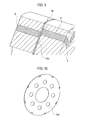
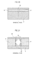
Fig. 1 ] Figure is an axial section of a rotor for a rotating electrical machine according toEmbodiment 1 of the present invention and an external view of a rotor blank. - [
Fig. 2] Figure 2 is an external view of the rotating electrical machine according toEmbodiment 1 of the present invention. - [
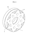
Fig. 3] Figure 3 is an external view of the rotor for the rotating electrical machine according toEmbodiment 1 of the present invention. - [
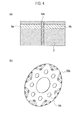
Fig. 4] Figure 4 is an axial section of a rotor for a rotating electrical machine according toEmbodiment 2 of the present invention and an external view of a rotor blank. - [
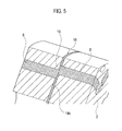
Fig. 5] Figure 5 is an axially sectioned perspective view of a rotor for a rotating electrical machine according toEmbodiment 3 of the present invention. - [
Fig. 6] Figure 6 is an external view of a rotor blank according toEmbodiment 3 of the present invention. - [
Fig. 7] Figure 7 is an enlarged view of the rotor blank according toEmbodiment 3 of the present invention. - [
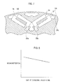
Fig. 8] Figure 8 is a view illustrating a relationship between a gap on a divisional skew plane in the rotor for a rotating electrical machine according toEmbodiment 3 of the present invention. - [
Fig. 9] Figure 9 is an axially sectioned perspective view of a rotor for a rotating electrical machine according toEmbodiment 4 of the present invention. - [
Fig. 10] Figure 10 is an external view of a rotor blank according toEmbodiment 4 of the present invention. - [
Fig. 11] Figure 11 is an external view of a rotor for a rotating electrical machine according toEmbodiment 5 of the present invention. - [
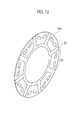
Fig. 12] Figure 12 is an external view of a rotor blank according toEmbodiment 5 of the present invention. - [
Fig. 13] Figure 13 is an axial section of a rotor for a rotating electrical machine according toEmbodiment 6 of the present invention. - [
Fig. 14] Figure 14 is an axial section of a rotor for a rotating electrical machine according to Embodiment 7 of the present invention. - [
Fig. 15] Figure 15 is a diametrical section of a rotor for a rotating electrical machine according to a related art. - [
Fig. 16] Figure 16 is a partial top view of the rotor for a rotating electrical machine according to the related art. - [
Fig. 17] Figure 17 is an external view of a rotor for a permanent-magnet rotating electrical machine according to the related art. - [
Fig. 18] Figure 18 is an axially sectioned perspective view of the rotor for a permanent-magnet rotating electrical machine according to the related art. - [
Fig. 19] Figure 19 is a view illustrating a magnetic flux density distribution of permanent magnets of the permanent-magnet rotating electrical machine according to the related art. - [
Fig. 20] Figure 20 is an axial section of the rotor for the permanent-magnet rotating electrical machine according to the related art. - [
Fig. 21] Figure 21 is an enlarged axial section of the rotor for the permanent-magnet rotating electrical machine according to the related art. - [
Fig. 22] Figure 22 is a view illustrating a permanent magnet demagnetization state of the permanent-magnet rotating electrical machine according to the related art. - Embodiments of the present invention will be explained in detail with reference to the drawings.
- First, a configuration of
Embodiment 1 will be explained with reference toFigs. 1 to 3 . Although the embodiment is described in connection with a permanent-magnet, reluctance-type rotating electrical machine having an 8-pole rotor, the present invention is executable on any rotating electrical machine employing permanent magnets without regard to the number of poles. The same or equivalent structural elements as those of the related art ofFigs. 15 to 22 are represented with the same reference marks, to omit repetition of explanation. - As illustrated in
Fig. 2 , astator 10 includes astator core 11 and anarmature coil 12. Thestator core 11 is a lamination of electromagnetic steel plates, and on inner circumferential side thereof, there are stator slots accommodating thearmature coil 12 andstator teeth 13 facing arotor 1. Therotor 1 is arranged on an inner side of thestator 10 and hasrotor cores 2 andpermanent magnets 6. Between therotor 1 and thestator teeth 13, there is a gap (air gap). - The
rotor 1 for the rotating electrical machine includes a plurality of therotor cores 2 that are stacked together. On each of therotor cores 2, a plurality of thepermanent magnets 6 are circumferentially arranged. Thepermanent magnets 6 are axially divided by the rotor cores and circumferentially form magnetic irregularities. As illustrated inFig. 3 , a plane that axially divides thepermanent magnets 6 is provided with a rotor blank 14a. Therotor 1 is constituted with a plurality of therotor cores 2 each being a block and thepermanent magnets 6 are axially divided by the blocks. Each rotor core block is formed with an electromagnetic steel plate or a plurality of electromagnetic steel plates that are laminated. - The
rotor 1 has permanent magnet embedding holes along easy axes of magnetization and thepermanent magnets 6 are embedded in the holes and are fixed thereto with an adhesive, to form eight magnetic projection poles and magnetic irregularities on an outer circumferential face. Thepermanent magnets 6 are inserted into the permanent magnet embedding holes in such a way as to cancel magnetic flux of armature current that crosses magnetic flux passing through a pole section and generating reluctance torque and suppress a leakage magnetic field at an end of a magnetic pole. Namely, thepermanent magnets 6 on each side of a pole section have the same magnetization direction and thepermanent magnets 6 on each side of an inter-pole section have opposite magnetization directions with respect to a circumferential direction of therotor 1. - In this way, the
rotor 1 circumferentially has the magnetic irregularities, and due to a rotating magnetic field produced by a current passing through thearmature coil 12 of thestator core 11, rotates around a rotor shaft. - Each
rotor core 2 consists of a lamination of electromagnetic steel plates and alternately has easy axes of magnetization and hard axes of magnetization in a circumferential direction around a rotation axis. To produce the magnetic irregularities, therotor core 2 is constituted by laminating the electromagnetic steel plates each having the permanent magnet embedding holes that are formed to receive the permanent magnets on a side face of a magnetic pole to generate reluctance torque according to a direction (easy axis of magnetization) of magnetic flux that passes through the magnetic pole and generates the reluctance torque. - The rotor blank 14a is arranged between adjacent block-
like rotor cores 2 and is made of nonmagnetic material. As illustrated inFigs. 1(a) and 1(b) , the rotor blank 14a haspermanent magnet holes 29a at positions where thepermanent magnets 6 are axially close to each other. Thepermanent magnets permanent magnet hole 29a form agap 15. Thepermanent magnets permanent magnets 6. This is also true in the below-mentioned embodiments. The nonmagnetic material is, for example, copper or stainless steel. - As illustrated in
Fig. 1(a) , thepermanent magnet 6 is axially divided by therotor cores 2 into thepermanent magnets axial gap 15. Since the rotor blank 14a is placed on the divisional plane, thegap 15 corresponds to thepermanent magnet hole 29a of the rotor blank 14a. When thepermanent magnets permanent magnets gap 15 at the divisional plane. - Next, operation of the embodiment with the above-mentioned configuration will be explained. As illustrated in
Fig. 1(a) , the divisional plane of therotor cores 2 andpermanent magnets 6 is provided with the rotor blank 14a made of nonmagnetic material. When the rotating electrical machine is operated with thegap 15 being present between the twopermanent magnets permanent magnets Fig. 21 . Accordingly, the end faces of thepermanent magnets gap 15 hardly cause demagnetization compared with the related art. - As mentioned above, the rotor for a rotating electrical machine according to
Embodiment 1 of the present invention has thegap 15 between thepermanent magnets rotor cores 2. Even with the gap, the embodiment can suppress demagnetization of thepermanent magnets permanent magnets gap 15. - The embodiment only inserts the rotor blank 14a made of nonmagnetic material along the divisional plane of the
rotor cores 2, to realize a simple structure and suppress demagnetization at low cost. - With reference to
Figs. 4(a) and 4(b) , a rotating electrical machine according toEmbodiment 2 of the present invention will be explained. InFigs. 4(a) and 4(b) , the same or equivalent structural elements as those ofFig. 1 are represented with the same reference marks, to omit repetition of explanation. - Basically, the configuration is the same as that of
Embodiment 1. Arotor 1 has a plurality ofrotor cores 2 that are stacked together and a plurality ofpermanent magnets 6 that are axially divided by therotor cores 2 and are circumferentially arranged on eachrotor core 2, to circumferentially form magnetic irregularities. A plane that axially divides thepermanent magnets 6 is provided with a rotor blank 14b made of nonmagnetic material. -
Embodiment 2 differs fromEmbodiment 1 in that apermanent magnet hole 29b of the rotor blank 14b is filled with nonmagnetic material. As illustrated inFig. 4(a) , there is no gap between thepermanent magnets permanent magnets - Next, operation of
Embodiment 2 with the above-mentioned configuration will be explained. As illustrated inFig. 4(a) , the divisional plane of therotor cores 2 andpermanent magnets 6 is provided with the rotor blank 14b made of nonmagnetic material. The gap between the twopermanent magnets permanent magnets Fig. 21 andEmbodiment 1. Accordingly, the end faces of thepermanent magnets - When assembling, the
permanent magnets Embodiment 1, there is nogap 15, and therefore, it is easy to axially position thepermanent magnets 6. If there is thegap 15, there is a possibility that the positions of thepermanent magnets gap 15. According to this embodiment, thepermanent magnets 6 never axially move or displace because the nonmagnetic material is present at the divisional plane. - As mentioned above, the rotor for a rotating electrical machine according to
Embodiment 2 of the present invention places the nonmagnetic material along the divisional plane of therotor cores 2 between and around thepermanent magnets
Accordingly, the embodiment can suppress demagnetization of thepermanent magnets permanent magnets gap 15. LikeEmbodiment 1,Embodiment 2 is achievable only by inserting the rotor blank 14a made of nonmagnetic material along the divisional plane of therotor cores 2. This is a simple structure that can suppress demagnetization at low cost. - Even if an adhesive to fix the
permanent magnets 6 to therotor cores 2 deteriorates or even during the assembling of the premagnetizedpermanent magnets 6, thepermanent magnets 6 are easily and accurately set at axial positions because there is nogap 15 on the divisional plane. This results in simplifying assembling steps including fine adjustment of the positions of the permanent magnets, reducing costs, and improving reliability. - With reference to
Figs. 5 to 8 , a configuration ofEmbodiment 3 of the present invention will be explained. The same or equivalent structural elements as those of the related art ofFigs. 15 to 22 and Embodiments 1 and 2 ofFigs. 1 to 4 are represented with the same reference marks, to omit repetition of explanation. - A
rotor 1 has a plurality ofrotor cores 2 that are stacked together and a plurality of permanent magnets that are axially divided by therotor cores 2 and are circumferentially arranged on eachrotor core 2, to circumferentially form magnetic irregularities. As illustrated inFig. 5 , the divisional plane (divisional skew plane 16) that axially divides thepermanent magnets 6 has a rotor blank 14c. - According to
Embodiment 3, therotor cores 2 are stacked together like the related art explained with reference toFig. 17 . The block-like rotor cores 2 are arranged in such a way that magnetic poles are circumferentially shifted from each other, to provide therotor 1 with bound stepped skews. As illustrated inFig. 5 , the rotor blank 14c is arranged between adjacent ones (divisional skew plane 16) of the block-like rotor cores 2 that are stacked together. Namely, thepermanent magnets 6 each form a skew structure (stepped skew) having a predetermined circumferential skew angle for eachrotor core 2. Eachpermanent magnet 6 is spaced from therotor core 2 that axially faces thepermanent magnet 6. - The rotor blank 14c has a
permanent magnet hole 29c at a position where the axially adjacentpermanent magnets 6 meet. Accordingly, as illustrated inFig. 6 , thepermanent magnet hole 29c is larger than thepermanent magnet holes permanent magnets 6 that form a skew structure. More precisely, as illustrated inFig. 7 , thepermanent magnet hole 29c of the rotor blank 14c is sized to accept thepermanent magnets permanent magnets Figs. 5 and7 , thepermanent magnets permanent magnet hole 29c. The contact position is a permanentmagnet contact part 20a illustrated inFig. 7 . Similarly, thepermanent magnets permanent magnet hole 29c. The contact position is a permanentmagnet contact part 20b illustrated inFig. 7 . - As illustrated in
Fig. 5 , thepermanent magnets 6 that axially face each other partly get in contact with each other (permanentmagnet contact part rotor cores 2, to form agap 19. - The rotor blank 14c according to
Embodiment 3 is made of nonmagnetic material. The remaining configuration ofEmbodiment 3 is the same asEmbodiment 1 and repetition of explanation is omitted. - Next, operation of
Embodiment 3 with the above-mentioned configuration will be explained. As mentioned above, thepermanent magnets 6 that axially face each other are spaced from therotor cores 2 that axially face the permanent magnets, to form thegap 19. When the rotating electrical machine is operated, thegap 19 prevents a demagnetizing field that is caused by an armature reaction and is applied at thedivisional skew plane 16 from therotor cores 2 to end faces of thepermanent magnets 6. As illustrated inFig. 8 , the larger thegap 19 at thedivisional skew plane 16, the more the demagnetization at the end faces of thepermanent magnets 6 is suppressed. - The rotor blank 14c according to
Embodiment 3 is made of nonmagnetic material. It may be made of the same material as therotor cores 2. In this case, it must have thepermanent magnet hole 29c conforming to thepermanent magnets 6 that axially adj oin. Because of thepermanent magnet hole 29c, thepermanent magnets 6 can form thegap 19 at thedivisional skew plane 16 with respect to the axially-opposingrotor cores 2. If there is nopermanent magnet hole 29c, thepermanent magnets 6 are axially in contact with the rotor blank 14c whose material is the same as that of therotor cores 2, demagnetization will not be suppressed. The rotor blank 14c made of nonmagnetic material according toEmbodiment 3 can suppress a demagnetizing field that is caused by an armature reaction and is applied from therotor cores 2 to end faces of thepermanent magnets 6. - As mentioned above, the rotor for a rotating electrical machine according to
Embodiment 3 of the present invention separates thepermanent magnets 6 that axially face each other from therotor cores 2 that axially face thepermanent magnets 6, to form thegap 19. This prevents a demagnetizing field acting on thepermanent magnets 6, thereby suppressing the demagnetization of thepermanent magnets 6 and improving reliability. This is particularly effective when thepermanent magnets 6 are magnetized after assembling (postmagnetizedmagnets) and when askew structure is employed. - The rotor blank 14c arranged along the
division skew plate 16 can be made of the same material as therotor cores 2. This reduces material cost. The rotor blank 14c arranged along thedivisional skew plane 16 may be made of nonmagnetic material. This further reduces a demagnetizing field acting on thepermanent magnets 6, thereby suppressing the demagnetization of thepermanent magnets 6 and further improving reliability. - With reference to
Figs. 9 and 10 , a configuration ofEmbodiment 4 of the present invention will be explained.Embodiment 4 differs fromEmbodiment 3 in that, as illustrated inFig. 10 , a rotor blank 14d has no permanent magnet holes. Accordingly, as illustrated inFig. 9 , adivisional skew plane 16 is entirely covered with the rotor blank 14d made of nonmagnetic material without gaps. - However, each of a plurality of
permanent magnets 6 has a skew structure with a predetermined circumferential angle with respect to eachrotor core 2 and is spaced from the facingrotor core 2, likeEmbodiment 3. This is because the rotor blank 14d is made of nonmagnetic material instead of the same material as therotor cores 2. The remaining configuration ofEmbodiment 4 is the same asEmbodiment 3, and therefore, repetition of explanation is omitted. - Operation of the embodiment with the above-mentioned configuration will be explained. As stated above, the
permanent magnets 6 that axially face each other are spaced from the axially facingrotor cores 2 by the rotor blank 14d made of nonmagnetic material interposed between them. When a rotating electrical machine is operated, the rotor blank 14d suppresses a demagnetizing field that is caused by an armature reaction at thedivisional skew plane 16 and is applied from therotor cores 2 to end faces of thepermanent magnets 6. When assembling therotor 1, thepermanent magnets 6 are fixed with the rotor blank 14d made of nonmagnetic material interposed along thedivisional skew plane 16. Accordingly, likeEmbodiment 2,Embodiment 4 allows thepermanent magnets 6 to be easily positioned in an axial direction. - In this way, the rotor for a rotating electrical machine according to
Embodiment 4 of the present invention spaces thepermanent magnets 6 that axially face each other from therotor cores 2 that axially face thepermanent magnets 6 by the rotor blank 14d made of nonmagnetic material interposed between them. This prevents a demagnetizing field acting on thepermanent magnets 6, thereby suppress ing the demagnetization of thepermanent magnets 6 and improving reliability. This is particularly effective when thepermanent magnets 6 are magnetized after assembling (postmagnetized magnets) and when a skew structure is employed.
The rotor blank 14d arranged along thedivisional skew plane 16 is made of nonmagnetic material, to reduce a demagnetizing field acting on thepermanent magnets 6, thereby suppressing the demagnetization of thepermanent magnets 6 and further improving reliability. - Even if an adhesive to fix the
permanent magnets 6 to therotor cores 2 deteriorates or even during the assembling of the premagnetizedpermanent magnets 6, the axial positioning of thepermanent magnets 6 is easily and accurately carried out because thedivisional skew plane 16 is provided with the rotary blank 14d made of nonmagnetic material. This results in simplifying assembling steps including fine adjustment of the positions of thepermanent magnets 6, reducing costs, and improving reliability. - With reference to
Figs. 11 and12 ,Embodiment 5 of the present invention will be explained. InFigs. 11 and12 , the same or equivalent structural elements as those of the related art andEmbodiments 1 to 4 are represented with the same reference marks, to omit repetition of explanation. - In a
rotor 1 illustrated inFig. 11 , a plurality ofrotor cores 2 are stacked together, and on eachrotor core 2,magnetic poles 23 are positioned as illustrated. Eachrotor core 2 has themagnetic poles 23 likeEmbodiments Embodiments Fig. 12 , a rotor blank 14e hasmagnetic sections 21 andnonmagnetic sections 22. - The rotor blank 14e is made of magnetic material (magnetic sections 21) at positions of the
magnetic poles 23 of the axiallyadjacent rotor cores 2 and nonmagnetic material (nonmagnetic sections 22) at nonmagnetic parts including positions where axially adjacent permanent magnets are present. - More precisely, the rotor blank 14e is made of magnetic material at positions the magnetic poles of the two axially
adjacent rotor cores 2 circumferentially overlap each other on each side of the rotor blank 14e. As illustrated inFig. 11 , themagnetic sections 21 are at positions where the magnetic poles of the twoadjacent rotor cores 2 circumferentially overlap each other on each side of the rotor blank 14e and correspond to sectors that include hatched part and extend toward the center of the rotor blank 14e. - The rotor blank 14e may have permanent magnet holes at locations where the permanent magnets adjoin. According to
Embodiment 5, there are no permanent magnet holes and the parts in question are made of nonmagnetic material. - The
permanent magnets 6 are circumferentially shifted rotor core by rotor core by a predetermined angle, to form a skew structure and are spaced from therotor cores 2 that axially face thepermanent magnets 6, likeEmbodiments - The
rotor 1 for a rotating electrical machine according to this embodiment has a cooling path to cool the sections made of nonmagnetic material of the rotor blank 14e. The cooling path is made by arranging a groove on adivisional skew plane 16 at, for example, gaps between the permanent magnets. The remaining configuration thereof is the same asEmbodiment 4 and repetition of explanation is omitted. - Next, operation of
Embodiment 5 with the above-mentioned configuration will be explained. As mentioned above, thepermanent magnets 6 that axially face each other are spaced from therotor cores 2 that axially face the permanent magnets by thenonmagnetic sections 22 of the rotor blank 14e interposed between them. When the rotating electrical machine is operated, the rotor blank 14e suppresses a demagnetizing field that is caused by an armature reaction at thedivisional skew plane 16 and is applied from therotor cores 2 to end faces of thepermanent magnets 6. - When assembling the
rotor 1, thepermanent magnets 6 are fixed with thenonmagnetic sections 22 of the rotor blank 14e interposed along thedivisional skew plane 16. Accordingly, likeEmbodiment 4,Embodiment 5 allows thepermanent magnets 6 to be easily positioned in an axial direction. The rotor blank 14e has themagnetic sections 21 made of magnetic material at the magnetic poles, to form magnetic irregularities and provide reluctance torque. The cooling path provided for thenonmagnetic sections 22 of the rotor blank 14e is used to pass a coolant such as air and oil, to enhance the cooling of the end faces of thepermanent magnets 6 on, for example, thedivisional skew plane 16, thereby lowering the temperature of thepermanent magnets 6. - In this way, the rotor for a rotating electrical machine according to
Embodiment 5 of the present invention spaces thepermanent magnets 6 that axially face each other from therotor cores 2 that axially face thepermanent magnets 6 by thenonmagnetic sections 22 of the rotor blank 14e interposed between them. This blocks a demagnetizing field acting on thepermanent magnets 6, thereby suppressing the demagnetization of thepermanent magnets 6 and improving reliability. - Further, the
nonmagnetic sections 22 of the rotor blank 14e on thedivisional skew plane 16 are made of nonmagnetic material, to further reduce the demagnetizing field acting on thepermanent magnets 6, thereby suppressing the demagnetization of thepermanent magnets 6 and improving reliability. - Even if an adhesive to fix the
permanent magnets 6 to therotor cores 2 deteriorates or even during the assembling of the premagnetizedpermanent magnets 6, the axial positioning of thepermanent magnets 6 is easily and accurately carried out because thedivisional skew plane 16 is provided with thenonmagnetic sections 22 of the rotary blank 14e. This results in simplifying assembling steps including fine adjustment of the positions of thepermanent magnets 6, reducingcosts, and improving reliability. - The rotor blank 14e has the
magnetic sections 21 made of magnetic material at positions corresponding to the magneticpoles, to form magnetic irregularities, provide reluctance torque, and improve the torque and output of the rotating electrical machine. - The cooling path provided for the
nonmagnetic sections 22 of the rotor blank 14e enhances the cooling of the end faces of thepermanent magnets 6 on thedivisional skew plane 16, thereby lowering the temperature of thepermanent magnets 6, securing the coercive force (demagnetization resistivity) thereof, and improving reliability. -
Figure 13 is an axial section of a rotor for a rotating electrical machine according toEmbodiment 6 of the present invention. Although therotor 1 inFig. 13 has no skew structure, it may have a skew structure. This embodiment differs fromEmbodiments 1 to 5 in that it has no rotor blank. However, it may have a rotor blank. A plurality ofpermanent magnets 6 are each made of a demagnetization resistive magnet (high-coercive-force permanent magnet 24) at an end face that faces a divisional plane. Namely, the high-coercive-forcepermanent magnet 24 forms a part of thepermanent magnet 6. The remaining configuration of this embodiment is the same asEmbodiments 1 to 5 and repetition of explanation is omitted. - Next, operation of the embodiment with the above-mentioned configuration will be explained. As explained above, each of the
permanent magnets 6 that axially face each other has the magnet (high-coercive-force permanent magnet 24) having demagnetization resistivity at an end facing the divisional plane. When the rotating electrical machine is operated, improved demagnetization resistivity is demonstrated against a demagnetizing field that is caused by an armature reaction and is applied fromrotor cores 2 at the divisional plane. - A not-illustrated cooling unit (for example, the above-mentioned cooling path) may be arranged to cool the end face of each
permanent magnet 6 facing the divisional plane. In this case, the not-illustrated cooling path passes a coolant such as air and oil, to enhance the cooling of the end faces of thepermanent magnets 6 facing the divisional plane, thereby lowering the temperature of thepermanent magnets 6. - In this way, the rotor for a rotating electrical machine according to
Embodiment 6 of the present invention provides each end of each of thepermanent magnets 6 that axially face each other with a magnet (high-coercive-force permanent magnet 24) having demagnetization resistivity. Without regard to a demagnetizing field acting on thepermanent magnets 6, the embodiment can improve the demagnetization resistivity of thepermanent magnets 6, suppress demagnetization thereof, and improve reliability. - If the not-illustrated cooling unit is arranged to cool the end face of each
permanent magnet 6 facing the divisional plane, it enhances the cooling of the end faces of thepermanent magnets 6 facing the divisional plane, thereby lowering the temperature of thepermanent magnets 6, securing the coercive force (demagnetization resistivity) thereof, and improving reliability. -
Figure 14 is an axial section of a rotor for a rotating electrical machine according to Embodiment 7 of the present invention. Although therotor 1 inFig. 14 has no skew structure, it may have a skew structure. This embodiment differs fromEmbodiments 1 to 5 in that it has no rotor blank. However, it may have a rotor blank. Each ofpermanent magnets 6 has an end face (permanent magnet 25) facing a divisional plane made of a thick magnet (permanent magnet 25) that is thicker in a radial direction of the rotor than the remaining part (permanent magnet 6). Namely, thepermanent magnet 6 includes the thick magnet (permanent magnet 25) at the end facing the divisional plane, and at the remaining part, has a normal thickness. The remaining configuration of this embodiment is the same asEmbodiment 6, and therefore, repetition of explanation is omitted. - Next, operation of the embodiment with the above-mentioned configuration will be explained. Each end facing the divisional plane of each of the
permanent magnets 6 that axially face each other is provided with the thick magnet (permanent magnet 25). When the rotating electrical machine is operated, high magnetic force that is present at the divisional plane resists against a demagnetizing field that is caused by an armature reaction and is applied from therotor cores 2, thereby improving demagnetization resistivity. - In this way, the rotor for a rotating electrical machine according to Embodiment 7 forms each end facing the divisional plane of each of the permanent magnets that axially face each other with the thick magnet (permanent magnet 25), to increase magnetic force acting against a demagnetizing field on the
permanent magnets 6, heighten the demagnetization resistivity of thepermanent magnets 6 at the divisional plane and end faces thereof, suppress demagnetization, and improve reliability. - The rotors for rotating electrical machines according to the present invention are applicable to rotating electrical machines and vehicles that employ the rotating electrical machines as driving sources.
Claims (17)
- A rotor for a rotating electrical machine, comprising:a plurality of rotor cores each formed by laminating many steel plates, the plurality of rotor cores being arranged in a rotation axis direction, to constitute the rotor;a plurality of permanent magnets axially divided by the rotor cores and circumferentially arranged on each of the rotor cores, to circumferentially form magnetic irregularities; anda rotor blank made of nonmagnetic material arranged between those of the rotor cores that are adjacent to each other in the rotation axis direction.
- The rotor for a rotating electrical machine as set forth in claim 1, wherein:the rotor blank has permanent magnet holes at positions where the permanent magnets adjoin each other in the rotation axis direction, the permanent magnets that face each other on each side of the permanent magnet hole forming a gap.
- The rotor for a rotating electrical machine as set forth in claim 1, wherein:the rotor blank is made of nonmagnetic material without forming gaps at positions where the permanent magnets adjoin each other in the rotation axis direction.
- The rotor for a rotating electrical machine as set forth in any one of claims 1 to 3, wherein:each of the permanent magnets includes, at an end thereof that faces a divisional plane, a demagnetization resistive magnet.
- The rotor for a rotating electrical machine as set forth in any one of claims 1 to 3, wherein:each of the permanent magnets includes, at an end thereof that faces a divisional plane, a magnet that is thicker in a radial direction of the rotor than the remaining part of the permanent magnet.
- The rotor for a rotating electrical machine as set forth in any one of claims 1 to 3, comprising:a cooling unit to cool a divisional-plane-facing end of each of the permanent magnets.
- A rotor for a rotating electrical machine, comprising:a plurality of rotor cores each formed by laminating many steel plates, the plurality of rotor cores being arranged in a rotation axis direction, to constitute the rotor; anda plurality of permanent magnets axially divided by the rotor cores and circumferentially arranged on each of the rotor cores, to circumferentially form magnetic irregularities,the permanent magnets being circumferentially shifted rotor core by rotor core by a predetermined angle, to form a skew structure and being spaced from the rotor cores that face the permanent magnets in the rotation axis direction.
- The rotor for a rotating electrical machine as set forth in claim 7, comprising:a rotor blank arranged between those of the rotor cores that are adjacent to each other in the rotation axis direction.
- The rotor for a rotating electrical machine as set forth in claim 8, wherein:the rotor blank is made of nonmagnetic material.
- The rotor for a rotating electrical machine as set forth in claim 8 or 9, wherein:the rotor blank has permanent magnet holes at positions where the permanent magnets adjoin each other in the rotation axis direction.
- The rotor for a rotating electrical machine as set forth in claim 8 or 9, wherein:the rotor blank is made of magnetic material at positions of magnetic poles of the rotor cores that are adjacent to each other in the rotation axis direction and nonmagnetic material at parts other than the positions made of magnetic material, including parts where the permanent magnets adjoin each other in the rotation axis direction.
- The rotor for a rotating electrical machine as set forth in claim 11, wherein:the rotor blank is made of magnetic material at positions where magnetic poles of two of the rotor cores that face each other in the rotation axis direction on each side of the rotor blank circumferentially overlap each other.
- The rotor for a rotating electrical machine as set forth in claim 10, comprising:a cooling path to cool the parts of the rotor blank made of nonmagnetic material.
- The rotor for a rotating electrical machine as set forth in claim 12, comprising:a cooling path to cool the parts of the rotor blank made of nonmagnetic material.
- The rotor for a rotating electrical machine as set forth in claim 7 or 8, wherein:each of the permanent magnets includes, at an end thereof that faces a divisional plane, a demagnetization resistive magnet.
- The rotor for a rotating electrical machine as set forth in claim 7 or 8, wherein:each of the permanent magnets includes, at an end thereof that faces a divisional plane, a magnet that is thicker in a radial direction of the rotor than the remaining part of the permanent magnet.
- The rotor for a rotating electrical machine as set forth in claim 7 or 8, comprising:a cooling unit to cool a divisional-plane-facing end of each of the permanent magnets.
Applications Claiming Priority (2)
| Application Number | Priority Date | Filing Date | Title |
|---|---|---|---|
| JP2007307943A JP5238231B2 (en) | 2007-11-28 | 2007-11-28 | Rotating electrical machine rotor |
| PCT/JP2008/071294 WO2009069575A1 (en) | 2007-11-28 | 2008-11-25 | Rotary machine rotor |
Publications (3)
| Publication Number | Publication Date |
|---|---|
| EP2216883A1 true EP2216883A1 (en) | 2010-08-11 |
| EP2216883A4 EP2216883A4 (en) | 2016-08-24 |
| EP2216883B1 EP2216883B1 (en) | 2019-06-05 |
Family
ID=40678471
Family Applications (1)
| Application Number | Title | Priority Date | Filing Date |
|---|---|---|---|
| EP08855456.3A Active EP2216883B1 (en) | 2007-11-28 | 2008-11-25 | Rotor for a rotating electrical machine |
Country Status (5)
| Country | Link |
|---|---|
| US (1) | US8362668B2 (en) |
| EP (1) | EP2216883B1 (en) |
| JP (1) | JP5238231B2 (en) |
| CN (1) | CN101855808B (en) |
| WO (1) | WO2009069575A1 (en) |
Cited By (3)
| Publication number | Priority date | Publication date | Assignee | Title |
|---|---|---|---|---|
| EP2983273A4 (en) * | 2013-04-01 | 2016-12-28 | Fuji Electric Co Ltd | ROTATING PERMANENT MAGNET ELECTRICAL MACHINE |
| WO2024126259A1 (en) * | 2022-12-12 | 2024-06-20 | Zf Friedrichshafen Ag | Laminated rotor core with inclination, method for producing the laminated rotor core, and rotor having the laminated rotor core |
| EP4322375A4 (en) * | 2021-06-29 | 2025-05-21 | Zhejiang Founder Motor Co., Ltd | ROTOR UNIT, ROTOR AND MOTOR STRUCTURE |
Families Citing this family (44)
| Publication number | Priority date | Publication date | Assignee | Title |
|---|---|---|---|---|
| JP5581013B2 (en) * | 2009-06-23 | 2014-08-27 | 株式会社三井ハイテック | Rotor core |
| JP5454023B2 (en) * | 2009-09-07 | 2014-03-26 | ダイキン工業株式会社 | Electric motor |
| US8564168B2 (en) | 2010-05-24 | 2013-10-22 | Remy Technologies, L.L.C. | Rotor lamination assembly |
| JP5331761B2 (en) * | 2010-08-09 | 2013-10-30 | 株式会社日立製作所 | Permanent magnet rotating electric machine |
| JP2012125034A (en) * | 2010-12-08 | 2012-06-28 | Hitachi Ltd | Permanent magnet type rotary electric machine and manufacturing method for rotor thereof |
| JP5729090B2 (en) * | 2011-03-31 | 2015-06-03 | ダイキン工業株式会社 | Rotor and rotating electrical machine |
| JP2013031336A (en) * | 2011-07-29 | 2013-02-07 | Sim-Drive Co Ltd | Permanent magnet type synchronous motor |
| CN102412687A (en) * | 2011-11-30 | 2012-04-11 | 西安久和能源科技有限公司 | Megawatt-level water-cooling high-speed permanent magnet generator |
| FR2987184B1 (en) * | 2012-02-20 | 2016-07-29 | Moteurs Leroy-Somer | ROTOR OF ROTATING ELECTRIC MACHINE WITH FLOW CONCENTRATION. |
| JP5486036B2 (en) * | 2012-04-11 | 2014-05-07 | ファナック株式会社 | Electric motor having a rotor structure for preventing problems due to distortion caused by temperature change and method for manufacturing the same |
| JP2014072995A (en) * | 2012-09-28 | 2014-04-21 | Suzuki Motor Corp | Ipm type electric rotary machine |
| US9641033B2 (en) * | 2013-09-06 | 2017-05-02 | General Electric Company | Electric machine having offset rotor sections |
| US9906108B2 (en) | 2012-11-01 | 2018-02-27 | General Electric Company | Sensorless electric machine |
| US9871418B2 (en) | 2012-11-01 | 2018-01-16 | General Electric Company | Sensorless electric machine |
| JP2014128116A (en) * | 2012-12-26 | 2014-07-07 | Toyota Industries Corp | Permanent magnet embedded rotary electric machine |
| CN105009417B (en) * | 2013-01-28 | 2018-05-01 | 三菱电机株式会社 | Permanent magnet type rotating electric machine |
| US10199889B2 (en) * | 2013-06-20 | 2019-02-05 | Otis Elevator Company | Electric machine having rotor with slanted permanent magnets |
| JP5774081B2 (en) * | 2013-12-09 | 2015-09-02 | 三菱電機株式会社 | Rotating electric machine |
| JP2015177706A (en) * | 2014-03-18 | 2015-10-05 | 日産自動車株式会社 | Rotor structure of rotary electric machine |
| EP3026798B1 (en) | 2014-11-25 | 2020-10-14 | Black & Decker Inc. | Brushless motor for a power tool |
| JP6101733B2 (en) * | 2015-04-20 | 2017-03-22 | 本田技研工業株式会社 | Rotating electrical machine rotor |
| US10673291B2 (en) * | 2015-06-17 | 2020-06-02 | Mitsubishi Electric Corporation | Permanent-magnet electric motor |
| JP6661939B2 (en) | 2015-09-29 | 2020-03-11 | ダイキン工業株式会社 | Rotor |
| US10328566B2 (en) | 2015-10-14 | 2019-06-25 | Black & Decker Inc. | Brushless motor system for power tools |
| JP6597184B2 (en) * | 2015-10-29 | 2019-10-30 | アイシン精機株式会社 | Permanent magnet type motor |
| US10541577B2 (en) * | 2016-01-13 | 2020-01-21 | Ford Global Technologies, Llc | Utilization of magnetic fields in electric machines having skewed rotor sections and separators with cutouts |
| US20170201137A1 (en) * | 2016-01-13 | 2017-07-13 | Ford Global Technologies, Llc | Utilization of Magnetic Fields in Electric Machines |
| US10931155B2 (en) * | 2016-05-25 | 2021-02-23 | Mitsubishi Electric Corporation | Rotor, electric motor, compressor, air conditioner, and method for manufacturing electric motor |
| CN106059223B (en) * | 2016-05-25 | 2018-06-15 | 东南大学 | A kind of complementary type magnetic gear double-rotor machine |
| JP6832935B2 (en) * | 2016-08-22 | 2021-02-24 | 三菱電機株式会社 | Consequential pole type rotor, electric motor and air conditioner |
| JP6410776B2 (en) * | 2016-10-06 | 2018-10-24 | 本田技研工業株式会社 | Rotor manufacturing method |
| JP2018067978A (en) * | 2016-10-17 | 2018-04-26 | 日立オートモティブシステムズ株式会社 | Rotating electric machine and method of manufacturing rotating electric machine |
| JP6630690B2 (en) * | 2017-02-22 | 2020-01-15 | 本田技研工業株式会社 | Rotating electric machine rotor |
| JP6755840B2 (en) * | 2017-08-22 | 2020-09-16 | 株式会社東芝 | Rotating machine |
| US10256688B1 (en) * | 2017-10-10 | 2019-04-09 | Zero E Technologies, Llc | Electric machine rotor cooling systems and methods |
| US10505416B2 (en) * | 2017-11-09 | 2019-12-10 | Ford Global Technologies, Llc | Patterned offset pole rotor |
| JP7056743B2 (en) * | 2018-08-16 | 2022-04-19 | 三菱電機株式会社 | Rotating electric machine |
| JP7099936B2 (en) * | 2018-11-15 | 2022-07-12 | 株式会社三井ハイテック | Iron core products and manufacturing methods for iron core products |
| JP7108529B2 (en) * | 2018-12-26 | 2022-07-28 | 本田技研工業株式会社 | Rotating electric machine |
| JP6896029B2 (en) * | 2019-08-19 | 2021-06-30 | 三菱電機株式会社 | Rotating machine |
| US12266977B2 (en) | 2020-04-15 | 2025-04-01 | Panasonic Intellectual Property Management Co., Ltd. | Rotor and electric motor |
| JP7478104B2 (en) * | 2021-01-08 | 2024-05-02 | 株式会社アイシン | Rotor core |
| US11742734B2 (en) * | 2021-07-19 | 2023-08-29 | Abb Schweiz Ag | Permanent magnet machine and rotor therefor |
| DE102023115829A1 (en) * | 2023-06-16 | 2024-12-19 | Schaeffler Technologies AG & Co. KG | rotor and electric machine |
Family Cites Families (16)
| Publication number | Priority date | Publication date | Assignee | Title |
|---|---|---|---|---|
| DE2843375A1 (en) * | 1978-10-05 | 1980-04-24 | Bosch Gmbh Robert | Arc-shaped permanent magnet for small motor - has ends made narrower by using adjacent regions of high remanence and high coercive force |
| US6259180B1 (en) * | 1996-07-02 | 2001-07-10 | Schlenker Enterprises, Ltd. | Motor including embedded permanent magnet rotor and method for making the same |
| JPH08340651A (en) * | 1995-06-12 | 1996-12-24 | Toshiba Corp | Permanent magnet and permanent magnet type rotating electrical machine |
| JP2000308287A (en) * | 1999-04-19 | 2000-11-02 | Matsushita Electric Ind Co Ltd | Permanent magnet embedded type reluctance motor |
| DE60327743D1 (en) * | 2002-03-08 | 2009-07-09 | Lawrence P Zepp | BRUSHLESS PERMANENT MAGNETIC MOTOR OR ROTARY CURRENT GENERATOR WITH VARIABLE ROTOR / STATOR ALIGNMENT Z |
| KR100567130B1 (en) * | 2002-03-20 | 2006-03-31 | 다이킨 고교 가부시키가이샤 | Permanent magnet motor and compressor using it |
| JP2004248422A (en) * | 2003-02-14 | 2004-09-02 | Moric Co Ltd | Field magnet type rotary electric equipment |
| JP2004343915A (en) * | 2003-05-16 | 2004-12-02 | Nissan Motor Co Ltd | Electric motor |
| JP4070674B2 (en) | 2003-07-31 | 2008-04-02 | 株式会社東芝 | Reluctance rotor |
| JP2005057865A (en) * | 2003-08-01 | 2005-03-03 | Nissan Motor Co Ltd | Rotor structure |
| JP2005218228A (en) * | 2004-01-29 | 2005-08-11 | Asmo Co Ltd | Magnet-embedded motor |
| JP4491260B2 (en) * | 2004-03-15 | 2010-06-30 | 学校法人東京理科大学 | Rotor for bearingless motor and bearingless motor |
| JP4515236B2 (en) * | 2004-11-26 | 2010-07-28 | 本田技研工業株式会社 | Embedded magnet type rotor |
| JP4010319B2 (en) * | 2005-02-09 | 2007-11-21 | ダイキン工業株式会社 | Core and rotor, motor and compressor |
| JP4855125B2 (en) * | 2006-04-07 | 2012-01-18 | 株式会社三井ハイテック | Manufacturing method of rotor laminated core |
| KR101243670B1 (en) * | 2007-03-08 | 2013-03-18 | 엘지전자 주식회사 | Rotor of motor |
-
2007
- 2007-11-28 JP JP2007307943A patent/JP5238231B2/en active Active
-
2008
- 2008-11-25 WO PCT/JP2008/071294 patent/WO2009069575A1/en not_active Ceased
- 2008-11-25 US US12/745,108 patent/US8362668B2/en active Active
- 2008-11-25 CN CN200880115872.5A patent/CN101855808B/en active Active
- 2008-11-25 EP EP08855456.3A patent/EP2216883B1/en active Active
Non-Patent Citations (1)
| Title |
|---|
| See references of WO2009069575A1 * |
Cited By (5)
| Publication number | Priority date | Publication date | Assignee | Title |
|---|---|---|---|---|
| EP2983273A4 (en) * | 2013-04-01 | 2016-12-28 | Fuji Electric Co Ltd | ROTATING PERMANENT MAGNET ELECTRICAL MACHINE |
| US10158265B2 (en) | 2013-04-01 | 2018-12-18 | Fuji Electric Co., Ltd. | Embedded permanent magnet type rotating electric machine |
| EP4322375A4 (en) * | 2021-06-29 | 2025-05-21 | Zhejiang Founder Motor Co., Ltd | ROTOR UNIT, ROTOR AND MOTOR STRUCTURE |
| US12620856B2 (en) | 2021-06-29 | 2026-05-05 | Zhejiang Founder Motor Co., Ltd | Rotor unit, rotor, and motor structure |
| WO2024126259A1 (en) * | 2022-12-12 | 2024-06-20 | Zf Friedrichshafen Ag | Laminated rotor core with inclination, method for producing the laminated rotor core, and rotor having the laminated rotor core |
Also Published As
| Publication number | Publication date |
|---|---|
| CN101855808A (en) | 2010-10-06 |
| US8362668B2 (en) | 2013-01-29 |
| EP2216883B1 (en) | 2019-06-05 |
| US20100301697A1 (en) | 2010-12-02 |
| CN101855808B (en) | 2013-03-13 |
| JP2009136040A (en) | 2009-06-18 |
| WO2009069575A1 (en) | 2009-06-04 |
| EP2216883A4 (en) | 2016-08-24 |
| JP5238231B2 (en) | 2013-07-17 |
Similar Documents
| Publication | Publication Date | Title |
|---|---|---|
| US8362668B2 (en) | Rotor for rotating electrical machine | |
| US11277045B2 (en) | Radially embedded permanent magnet rotor and methods thereof | |
| CN108075585B (en) | Rotating electrical machine | |
| EP3457534B1 (en) | Rotating electric machine | |
| JP5502571B2 (en) | Permanent magnet rotating electric machine | |
| US9099905B2 (en) | Radially embedded permanent magnet rotor and methods thereof | |
| JP5813254B2 (en) | Permanent magnet rotating electric machine | |
| US10020698B2 (en) | Multi-gap type rotary electric machine including inner and outer stators and a rotor with inner and outer magnets | |
| US20140103771A1 (en) | Radially embedded permanent magnet rotor and methods thereof | |
| US20140103770A1 (en) | Permanent magnet rotor and methods thereof | |
| US20140103772A1 (en) | Radially embedded permanent magnet rotor and methods thereof | |
| CN103872868A (en) | Multi-gap type rotary electric machine | |
| JP2007104888A (en) | Rotary electric machine | |
| JP2011050216A (en) | Motor | |
| JPWO2017212575A1 (en) | Permanent magnet motor | |
| JP7318138B1 (en) | Rotors and Rotating Electric Machines | |
| JP2005057865A (en) | Rotor structure | |
| US12537404B2 (en) | Rotor | |
| CN113206564A (en) | Rotating electrical machine | |
| KR20160057766A (en) | Rotor structure of wrsm motor | |
| KR101150595B1 (en) | Rotor for synchronous reluctance motor | |
| CN117378126A (en) | Rotor and electric motor | |
| JP2007110868A (en) | Permanent magnet type motor | |
| JP2024136191A (en) | Rotating Electric Machine | |
| CN122055883A (en) | Rotor, motor, and method for manufacturing rotor |
Legal Events
| Date | Code | Title | Description |
|---|---|---|---|
| PUAI | Public reference made under article 153(3) epc to a published international application that has entered the european phase |
Free format text: ORIGINAL CODE: 0009012 |
|
| 17P | Request for examination filed |
Effective date: 20100512 |
|
| AK | Designated contracting states |
Kind code of ref document: A1 Designated state(s): AT BE BG CH CY CZ DE DK EE ES FI FR GB GR HR HU IE IS IT LI LT LU LV MC MT NL NO PL PT RO SE SI SK TR |
|
| AX | Request for extension of the european patent |
Extension state: AL BA MK RS |
|
| DAX | Request for extension of the european patent (deleted) | ||
| RA4 | Supplementary search report drawn up and despatched (corrected) |
Effective date: 20160726 |
|
| RIC1 | Information provided on ipc code assigned before grant |
Ipc: H02K 1/27 20060101ALI20160718BHEP Ipc: H02K 1/32 20060101ALI20160718BHEP Ipc: H02K 21/14 20060101ALI20160718BHEP Ipc: H02K 1/22 20060101AFI20160718BHEP |
|
| STAA | Information on the status of an ep patent application or granted ep patent |
Free format text: STATUS: EXAMINATION IS IN PROGRESS |
|
| 17Q | First examination report despatched |
Effective date: 20181126 |
|
| GRAP | Despatch of communication of intention to grant a patent |
Free format text: ORIGINAL CODE: EPIDOSNIGR1 |
|
| STAA | Information on the status of an ep patent application or granted ep patent |
Free format text: STATUS: GRANT OF PATENT IS INTENDED |
|
| INTG | Intention to grant announced |
Effective date: 20190320 |
|
| RIN1 | Information on inventor provided before grant (corrected) |
Inventor name: ITO, WATARU Inventor name: TOKUMASU, TADASHI Inventor name: MATSUBARA, MASAKTSU Inventor name: TAKABATAKE, MIKIO Inventor name: HASHIBA, YUTAKA Inventor name: SAKAI, KAZUTO Inventor name: ARATA, MASANORI Inventor name: TAKAHASHI, NORIO |
|
| GRAS | Grant fee paid |
Free format text: ORIGINAL CODE: EPIDOSNIGR3 |
|
| GRAA | (expected) grant |
Free format text: ORIGINAL CODE: 0009210 |
|
| STAA | Information on the status of an ep patent application or granted ep patent |
Free format text: STATUS: THE PATENT HAS BEEN GRANTED |
|
| AK | Designated contracting states |
Kind code of ref document: B1 Designated state(s): AT BE BG CH CY CZ DE DK EE ES FI FR GB GR HR HU IE IS IT LI LT LU LV MC MT NL NO PL PT RO SE SI SK TR |
|
| REG | Reference to a national code |
Ref country code: GB Ref legal event code: FG4D |
|
| RIN1 | Information on inventor provided before grant (corrected) |
Inventor name: HASHIBA, YUTAKA Inventor name: ARATA, MASANORI Inventor name: TAKABATAKE, MIKIO Inventor name: ITO, WATARU Inventor name: MATSUBARA, MASAKATSU Inventor name: TOKUMASU, TADASHI Inventor name: TAKAHASHI, NORIO Inventor name: SAKAI, KAZUTO |
|
| REG | Reference to a national code |
Ref country code: CH Ref legal event code: EP |
|
| REG | Reference to a national code |
Ref country code: AT Ref legal event code: REF Ref document number: 1140977 Country of ref document: AT Kind code of ref document: T Effective date: 20190615 |
|
| REG | Reference to a national code |
Ref country code: IE Ref legal event code: FG4D |
|
| REG | Reference to a national code |
Ref country code: DE Ref legal event code: R096 Ref document number: 602008060297 Country of ref document: DE |
|
| REG | Reference to a national code |
Ref country code: NL Ref legal event code: MP Effective date: 20190605 |
|
| REG | Reference to a national code |
Ref country code: LT Ref legal event code: MG4D |
|
| PG25 | Lapsed in a contracting state [announced via postgrant information from national office to epo] |
Ref country code: ES Free format text: LAPSE BECAUSE OF FAILURE TO SUBMIT A TRANSLATION OF THE DESCRIPTION OR TO PAY THE FEE WITHIN THE PRESCRIBED TIME-LIMIT Effective date: 20190605 Ref country code: SE Free format text: LAPSE BECAUSE OF FAILURE TO SUBMIT A TRANSLATION OF THE DESCRIPTION OR TO PAY THE FEE WITHIN THE PRESCRIBED TIME-LIMIT Effective date: 20190605 Ref country code: NO Free format text: LAPSE BECAUSE OF FAILURE TO SUBMIT A TRANSLATION OF THE DESCRIPTION OR TO PAY THE FEE WITHIN THE PRESCRIBED TIME-LIMIT Effective date: 20190905 Ref country code: HR Free format text: LAPSE BECAUSE OF FAILURE TO SUBMIT A TRANSLATION OF THE DESCRIPTION OR TO PAY THE FEE WITHIN THE PRESCRIBED TIME-LIMIT Effective date: 20190605 Ref country code: LT Free format text: LAPSE BECAUSE OF FAILURE TO SUBMIT A TRANSLATION OF THE DESCRIPTION OR TO PAY THE FEE WITHIN THE PRESCRIBED TIME-LIMIT Effective date: 20190605 Ref country code: FI Free format text: LAPSE BECAUSE OF FAILURE TO SUBMIT A TRANSLATION OF THE DESCRIPTION OR TO PAY THE FEE WITHIN THE PRESCRIBED TIME-LIMIT Effective date: 20190605 |
|
| PG25 | Lapsed in a contracting state [announced via postgrant information from national office to epo] |
Ref country code: LV Free format text: LAPSE BECAUSE OF FAILURE TO SUBMIT A TRANSLATION OF THE DESCRIPTION OR TO PAY THE FEE WITHIN THE PRESCRIBED TIME-LIMIT Effective date: 20190605 Ref country code: BG Free format text: LAPSE BECAUSE OF FAILURE TO SUBMIT A TRANSLATION OF THE DESCRIPTION OR TO PAY THE FEE WITHIN THE PRESCRIBED TIME-LIMIT Effective date: 20190905 Ref country code: GR Free format text: LAPSE BECAUSE OF FAILURE TO SUBMIT A TRANSLATION OF THE DESCRIPTION OR TO PAY THE FEE WITHIN THE PRESCRIBED TIME-LIMIT Effective date: 20190906 |
|
| REG | Reference to a national code |
Ref country code: AT Ref legal event code: MK05 Ref document number: 1140977 Country of ref document: AT Kind code of ref document: T Effective date: 20190605 |
|
| PG25 | Lapsed in a contracting state [announced via postgrant information from national office to epo] |
Ref country code: PT Free format text: LAPSE BECAUSE OF FAILURE TO SUBMIT A TRANSLATION OF THE DESCRIPTION OR TO PAY THE FEE WITHIN THE PRESCRIBED TIME-LIMIT Effective date: 20191007 Ref country code: SK Free format text: LAPSE BECAUSE OF FAILURE TO SUBMIT A TRANSLATION OF THE DESCRIPTION OR TO PAY THE FEE WITHIN THE PRESCRIBED TIME-LIMIT Effective date: 20190605 Ref country code: EE Free format text: LAPSE BECAUSE OF FAILURE TO SUBMIT A TRANSLATION OF THE DESCRIPTION OR TO PAY THE FEE WITHIN THE PRESCRIBED TIME-LIMIT Effective date: 20190605 Ref country code: NL Free format text: LAPSE BECAUSE OF FAILURE TO SUBMIT A TRANSLATION OF THE DESCRIPTION OR TO PAY THE FEE WITHIN THE PRESCRIBED TIME-LIMIT Effective date: 20190605 Ref country code: AT Free format text: LAPSE BECAUSE OF FAILURE TO SUBMIT A TRANSLATION OF THE DESCRIPTION OR TO PAY THE FEE WITHIN THE PRESCRIBED TIME-LIMIT Effective date: 20190605 Ref country code: CZ Free format text: LAPSE BECAUSE OF FAILURE TO SUBMIT A TRANSLATION OF THE DESCRIPTION OR TO PAY THE FEE WITHIN THE PRESCRIBED TIME-LIMIT Effective date: 20190605 Ref country code: RO Free format text: LAPSE BECAUSE OF FAILURE TO SUBMIT A TRANSLATION OF THE DESCRIPTION OR TO PAY THE FEE WITHIN THE PRESCRIBED TIME-LIMIT Effective date: 20190605 |
|
| PG25 | Lapsed in a contracting state [announced via postgrant information from national office to epo] |
Ref country code: IS Free format text: LAPSE BECAUSE OF FAILURE TO SUBMIT A TRANSLATION OF THE DESCRIPTION OR TO PAY THE FEE WITHIN THE PRESCRIBED TIME-LIMIT Effective date: 20191005 |
|
| REG | Reference to a national code |
Ref country code: DE Ref legal event code: R097 Ref document number: 602008060297 Country of ref document: DE |
|
| PG25 | Lapsed in a contracting state [announced via postgrant information from national office to epo] |
Ref country code: TR Free format text: LAPSE BECAUSE OF FAILURE TO SUBMIT A TRANSLATION OF THE DESCRIPTION OR TO PAY THE FEE WITHIN THE PRESCRIBED TIME-LIMIT Effective date: 20190605 |
|
| PLBE | No opposition filed within time limit |
Free format text: ORIGINAL CODE: 0009261 |
|
| STAA | Information on the status of an ep patent application or granted ep patent |
Free format text: STATUS: NO OPPOSITION FILED WITHIN TIME LIMIT |
|
| PG25 | Lapsed in a contracting state [announced via postgrant information from national office to epo] |
Ref country code: PL Free format text: LAPSE BECAUSE OF FAILURE TO SUBMIT A TRANSLATION OF THE DESCRIPTION OR TO PAY THE FEE WITHIN THE PRESCRIBED TIME-LIMIT Effective date: 20190605 Ref country code: DK Free format text: LAPSE BECAUSE OF FAILURE TO SUBMIT A TRANSLATION OF THE DESCRIPTION OR TO PAY THE FEE WITHIN THE PRESCRIBED TIME-LIMIT Effective date: 20190605 |
|
| 26N | No opposition filed |
Effective date: 20200306 |
|
| PG25 | Lapsed in a contracting state [announced via postgrant information from national office to epo] |
Ref country code: SI Free format text: LAPSE BECAUSE OF FAILURE TO SUBMIT A TRANSLATION OF THE DESCRIPTION OR TO PAY THE FEE WITHIN THE PRESCRIBED TIME-LIMIT Effective date: 20190605 |
|
| REG | Reference to a national code |
Ref country code: CH Ref legal event code: PL |
|
| PG25 | Lapsed in a contracting state [announced via postgrant information from national office to epo] |
Ref country code: MC Free format text: LAPSE BECAUSE OF FAILURE TO SUBMIT A TRANSLATION OF THE DESCRIPTION OR TO PAY THE FEE WITHIN THE PRESCRIBED TIME-LIMIT Effective date: 20190605 Ref country code: LU Free format text: LAPSE BECAUSE OF NON-PAYMENT OF DUE FEES Effective date: 20191125 Ref country code: LI Free format text: LAPSE BECAUSE OF NON-PAYMENT OF DUE FEES Effective date: 20191130 Ref country code: CH Free format text: LAPSE BECAUSE OF NON-PAYMENT OF DUE FEES Effective date: 20191130 |
|
| REG | Reference to a national code |
Ref country code: BE Ref legal event code: MM Effective date: 20191130 |
|
| GBPC | Gb: european patent ceased through non-payment of renewal fee |
Effective date: 20191125 |
|
| PG25 | Lapsed in a contracting state [announced via postgrant information from national office to epo] |
Ref country code: IE Free format text: LAPSE BECAUSE OF NON-PAYMENT OF DUE FEES Effective date: 20191125 Ref country code: GB Free format text: LAPSE BECAUSE OF NON-PAYMENT OF DUE FEES Effective date: 20191125 |
|
| PG25 | Lapsed in a contracting state [announced via postgrant information from national office to epo] |
Ref country code: BE Free format text: LAPSE BECAUSE OF NON-PAYMENT OF DUE FEES Effective date: 20191130 |
|
| PG25 | Lapsed in a contracting state [announced via postgrant information from national office to epo] |
Ref country code: CY Free format text: LAPSE BECAUSE OF FAILURE TO SUBMIT A TRANSLATION OF THE DESCRIPTION OR TO PAY THE FEE WITHIN THE PRESCRIBED TIME-LIMIT Effective date: 20190605 |
|
| PG25 | Lapsed in a contracting state [announced via postgrant information from national office to epo] |
Ref country code: HU Free format text: LAPSE BECAUSE OF FAILURE TO SUBMIT A TRANSLATION OF THE DESCRIPTION OR TO PAY THE FEE WITHIN THE PRESCRIBED TIME-LIMIT; INVALID AB INITIO Effective date: 20081125 Ref country code: MT Free format text: LAPSE BECAUSE OF FAILURE TO SUBMIT A TRANSLATION OF THE DESCRIPTION OR TO PAY THE FEE WITHIN THE PRESCRIBED TIME-LIMIT Effective date: 20190605 |
|
| PGFP | Annual fee paid to national office [announced via postgrant information from national office to epo] |
Ref country code: FR Payment date: 20250930 Year of fee payment: 18 |
|
| PGFP | Annual fee paid to national office [announced via postgrant information from national office to epo] |
Ref country code: DE Payment date: 20250930 Year of fee payment: 18 |
|
| PGFP | Annual fee paid to national office [announced via postgrant information from national office to epo] |
Ref country code: IT Payment date: 20251022 Year of fee payment: 18 |