EP2216536A2 - Rückschlagventil - Google Patents
Rückschlagventil Download PDFInfo
- Publication number
- EP2216536A2 EP2216536A2 EP09176024A EP09176024A EP2216536A2 EP 2216536 A2 EP2216536 A2 EP 2216536A2 EP 09176024 A EP09176024 A EP 09176024A EP 09176024 A EP09176024 A EP 09176024A EP 2216536 A2 EP2216536 A2 EP 2216536A2
- Authority
- EP
- European Patent Office
- Prior art keywords
- valve
- housing
- check valve
- closure member
- check
- Prior art date
- Legal status (The legal status is an assumption and is not a legal conclusion. Google has not performed a legal analysis and makes no representation as to the accuracy of the status listed.)
- Granted
Links
Images
Classifications
-
- F—MECHANICAL ENGINEERING; LIGHTING; HEATING; WEAPONS; BLASTING
- F16—ENGINEERING ELEMENTS AND UNITS; GENERAL MEASURES FOR PRODUCING AND MAINTAINING EFFECTIVE FUNCTIONING OF MACHINES OR INSTALLATIONS; THERMAL INSULATION IN GENERAL
- F16K—VALVES; TAPS; COCKS; ACTUATING-FLOATS; DEVICES FOR VENTING OR AERATING
- F16K15/00—Check valves
- F16K15/14—Check valves with flexible valve members
- F16K15/16—Check valves with flexible valve members with tongue-shaped laminae
-
- F—MECHANICAL ENGINEERING; LIGHTING; HEATING; WEAPONS; BLASTING
- F02—COMBUSTION ENGINES; HOT-GAS OR COMBUSTION-PRODUCT ENGINE PLANTS
- F02M—SUPPLYING COMBUSTION ENGINES IN GENERAL WITH COMBUSTIBLE MIXTURES OR CONSTITUENTS THEREOF
- F02M26/00—Engine-pertinent apparatus for adding exhaust gases to combustion-air, main fuel or fuel-air mixture, e.g. by exhaust gas recirculation [EGR] systems
- F02M26/02—EGR systems specially adapted for supercharged engines
- F02M26/09—Constructional details, e.g. structural combinations of EGR systems and supercharger systems; Arrangement of the EGR and supercharger systems with respect to the engine
- F02M26/10—Constructional details, e.g. structural combinations of EGR systems and supercharger systems; Arrangement of the EGR and supercharger systems with respect to the engine having means to increase the pressure difference between the exhaust and intake system, e.g. venturis, variable geometry turbines, check valves using pressure pulsations or throttles in the air intake or exhaust system
-
- F—MECHANICAL ENGINEERING; LIGHTING; HEATING; WEAPONS; BLASTING
- F02—COMBUSTION ENGINES; HOT-GAS OR COMBUSTION-PRODUCT ENGINE PLANTS
- F02M—SUPPLYING COMBUSTION ENGINES IN GENERAL WITH COMBUSTIBLE MIXTURES OR CONSTITUENTS THEREOF
- F02M26/00—Engine-pertinent apparatus for adding exhaust gases to combustion-air, main fuel or fuel-air mixture, e.g. by exhaust gas recirculation [EGR] systems
- F02M26/13—Arrangement or layout of EGR passages, e.g. in relation to specific engine parts or for incorporation of accessories
- F02M26/40—Arrangement or layout of EGR passages, e.g. in relation to specific engine parts or for incorporation of accessories with timing means in the recirculation passage, e.g. cyclically operating valves or regenerators; with arrangements involving pressure pulsations
Definitions
- the invention relates to a check valve for gas-carrying lines in the field of internal combustion engines with a housing having at least one valve seat with a valve opening, a valve plate member and a valve stop member, wherein the valve plate member is formed as a leaf spring element.
- check valve From the DE 199 53 198 A1 Such a check valve is known.
- This type of check valves is used in particular in the field of exhaust gas recirculation, wherein the pressure in the charge air line can be greater than the pressure in the exhaust gas recirculation line and accordingly a penetration of charge air into the exhaust gas recirculation line to be prevented.
- the assembly effort is high, especially in multi-flow such check valves.
- the invention is therefore an object of the invention to provide a check valve, which requires a much lower installation costs and is therefore less expensive to manufacture.
- valve plate element and the valve stop element are designed as a one-piece valve closure member.
- the valve closure member is designed as a stamped and bent part.
- the valve closure member may have an elastomer coating.
- at least the region of the valve seat of the housing may have a thermally loadable elastomer coating in order to ensure a good seal in the closed state.
- the housing may have a clamping groove in which the valve closure member is mounted positively and non-positively.
- the valve closure member may also be non-positively connect the valve closure member via the valve stop member, for example by a rivet, screw, etc. to the housing.
- the housing has connecting pins.
- the housing may have a circumferential sealing member which on the one hand ensures a sealing effect between a gas-carrying line and the check valve and on the other hand supports the check valve damping in the gas-carrying line. It is also possible that the housing has a plurality of valve openings.
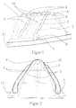
- FIG. 1 shows a perspective view of an inventive check valve 1, which is designed as a four-flow check valve, ie with four valve openings 2.
- the check valve 1 is installed in the present case in an exhaust gas recirculation line, not shown, and is intended to ensure that when the charge air pressure is greater than the average exhaust pressure, the exhaust gas recirculation line is quickly closed to prevent charge air from entering the exhaust gas recirculation line.
- individual exhaust gas recirculation lines of course interact with individual charge air lines.
- the check valve according to the invention has a housing 3, which in the present case has four valve openings 2, which each form a valve seat. These valve openings can be closed by a valve closure member 4.
- the valve closure member 4 is performed according to the invention as a stamped and bent part and includes both valve plate elements 5, which can close the respective valve openings 2 at too high a charge air pressure, as well as valve stop elements 6, which limit the deflection of the valve plate elements 5.
- the valve closure member 4 is mounted with a transition section 7 in a clamping groove 8 and also connected non-positively via screws 9 with connecting pin 10 of the housing 3.
- a circumferential sealing member 11 is provided.
- the housing 3 can be made of aluminum or a thermoset, for example, wherein the region of the valve seats is coated with a thermally resilient elastomer to ensure optimum sealing.
- FIG. 2 The check valve 1 according to the invention is shown once more in a sectional view.
- the check valve 1 is here in an open position, ie in a position in which the valve plate element 5 is lifted from the valve opening 2 and the associated valve seat and abuts against the stop element 6.
Landscapes
- Engineering & Computer Science (AREA)
- General Engineering & Computer Science (AREA)
- Mechanical Engineering (AREA)
- Chemical & Material Sciences (AREA)
- Combustion & Propulsion (AREA)
- Check Valves (AREA)
Abstract
Description
- Die Erfindung betrifft ein Rückschlagventil für gasführende Leitungen im Bereich von Brennkraftmaschinen mit einem Gehäuse, das mindestens einen Ventilsitz mit einer Ventilöffnung, ein Ventilplattenelement und ein Ventilanschlagelement aufweist, wobei das Ventilplattenelement als Blattfederelement ausgebildet ist.
- Aus der
DE 199 53 198 A1 ist ein derartiges Rückschlagventil bekannt. Diese Art von Rückschlagventilen wird insbesondere im Bereich der Abgasrückführung eingesetzt, wobei der Druck in der Ladeluftleitung größer als der Druck in der Abgasrückführleitung sein kann und dementsprechend ein Eindringen von Ladeluft in die Abgasrückführleitung verhindert werden soll. Trotz der geringen Bauteileanzahl ist der Montageaufwand vor allem bei mehrflutigen derartigen Rückschlagventilen hoch. - Daher liegt der Erfindung die Aufgabe zugrunde, ein Rückschlagventil zu verschaffen, das einen wesentlich geringeren Montageaufwand benötigt und dementsprechend kostengünstiger in der Herstellung ist.
- Diese Aufgabe wird bei einem gattungsgemäßen Rückschlagventil dadurch gelöst, dass das Ventilplattenelement und das Ventilanschlagelement als einteiliges Ventilverschlussorgan ausgeführt sind. Auf diese Weise wird eine besonders einfache und damit kostengünstige Montage des Rückschlagventils gewährleistet. Als besonders vorteilhaft hat es sich erwiesen, dass das Ventilverschlussorgan als Stanz-Biegeteil ausgeführt ist. Hierbei kann das Ventilverschlussorgan eine Elastomerbeschichtung aufweisen. Daüberhinaus kann auch zumindest der Bereich des Ventilsitzes des Gehäuses eine thermisch belastbare Elastomerbeschichtung aufweisen, um eine gute Abdichtung im geschlossenen Zustand zu gewährleisten.
- Um die Montage noch weiter zu vereinfachen, kann das Gehäuse eine Klemmnut besitzen, in der das Ventilverschlussorgan form- und kraftschlüssig gelagert ist. Darüber hinaus ist es auch möglich, das Ventilverschlussorgan über das Ventilanschlagelement kraftschlüssig, zum Beispiel durch eine Niet-, Schraubverbindung, etc. mit dem Gehäuse zu verbinden. In diesem Fall ist es besonders vorteilhaft, wenn das Gehäuse Anschlusszapfen aufweist.
- Auch kann das Gehäuse ein umlaufendes Abdichtorgan aufweisen, das einerseits eine Dichtwirkung zwischen einer gasführenden Leitung und dem Rückschlagventil gewährleistet und andererseits das Rückschlagventil dämpfend in der gasführenden Leitung lagert. Auch ist es möglich, dass das Gehäuse mehrere Ventilöffnungen aufweist.
- Ein Ausführungsbeispiel der Erfindung ist in der Zeichnung dargestellt und wird nachfolgend beschrieben.
-
- Figur 1:
- eine perspektivische Ansicht eines vierflutigen Rückschlagventils,
- Figur 2:
- eine Schnittansicht des Rückschlagventils aus
Figur 1 . -
Figur 1 zeigt in perspektivischer Ansicht ein erfindungsgemäßes Rückschlagventil 1, das als vierflutiges Rückschlagventil, also mit vier Ventilöffnungen 2 ausgebildet ist. Das Rückschlagventil 1 ist im vorliegenden Fall in einer nicht näher dargestellten Abgasrückführleitung eingebaut und soll gewährleisten, dass wenn der Ladeluftdruck größer ist als der mittlere Abgasdruck die Abgasrückführleitung schnell geschlossen wird, um zu verhindern, dass Ladeluft in die Abgasrückführleitung gelangt. Hierzu können, wenn gewünscht, einzelne Abgasrückführleitungen natürlich mit einzelnen Ladeluftleitungen zusammenwirken. - Das erfindungsgemäße Rückschlagventil besitzt ein Gehäuse 3, das im vorliegenden Fall vier Ventilöffnungen 2 aufweist, die jeweils einen Ventilsitz bilden. Diese Ventilöffnungen sind durch ein Ventilverschlussorgan 4 verschließbar. Das Ventilverschlussorgan 4 ist erfindungsgemäß als Stanzbiegeteil ausgeführt und umfasst sowohl Ventilplattenelemente 5, die die jeweiligen Ventilöffnungen 2 bei einem zu hohen Ladeluftdruck verschließen können, als auch Ventilanschlagelemente 6, die den Ausschlag der Ventilplattenelemente 5 begrenzen. Das Ventilverschlussorgan 4 ist mit einem Übergangsabschnitt 7 in einer Klemmnut 8 gelagert und zudem noch über Schrauben 9 mit Anschlusszapfen 10 des Gehäuses 3 kraftschlüssig verbunden. Um nun eine gute Dichtwirkung des Rückschlagventils 1 zwischen der Abgasrückführleitung und dem Gehäuse 3 zu erzielen, und des Weiteren das Gehäuse 3 dämpfend in der Abgasrückführleitung zu lagern, ist ein umlaufendes Abdichtorgan 11 vorgesehen. Darüberhinaus kann das Gehäuse 3 beispielsweise aus Aluminium oder einem Duroplast hergestellt sein, wobei der Bereich der Ventilsitze mit einem thermisch belastbaren Elastomer beschichtet ist, um eine optimale Abdichtung zu gewährleisten.
-
Figur 2 zeigt nun noch einmal in einer Schnittansicht das erfindungsgemäße Rückschlagventil 1. Besonders gut zu erkennen ist hierbei die Befestigung des Ventilverschlussorgans 4 über Schraube 9 in den Anschlusszapfen 10. Das Rückschlagventil 1 ist hier in einer geöffneten Position, also in einer Position in der das Ventilplattenelement 5 von der Ventilöffnung 2 und dem damit verbundenen Ventilsitz abgehoben ist und gegen das Anschlagselement 6 anliegt.
Claims (9)
- Rückschlagventil (1) für gasführende Leitungen im Bereich von Brennkraftmaschinen mit einem Gehäuse (3), das mindestens einen Ventilsitz mit einer Ventilöffnung (2), ein Ventilplattenelement (5) und ein Ventilanschlagelement (6) aufweist, wobei das Ventilplattenelement (5) als Blattfederelement ausgebildet ist, dadurch gekennzeichnet, dass das Ventilplattenelement (5) und das Ventilanschlagelement (6) als einteiliges Ventilverschlussorgan (4) ausgeführt sind.
- Rückschlagventil nach Anspruch 1, dadurch gekennzeichnet, dass das Ventilverschlussorgan (4) als Stanz-Biegeteil ausgeführt ist.
- Rückschlagventil nach Anspruch 1 oder 2, dadurch gekennzeichnet, dass das Ventilverschlussorgan (4) eine Elastomerbeschichtung aufweist.
- Rückschlagventil nach einem der vorhergehenden Ansprüche, dadurch gekennzeichnet, dass zumindest der Bereich des Ventilsitzes des Gehäuses (3) eine thermisch belastbare Elastomerbeschichtung aufweist.
- Rückschlagventil nach einem der vorhergehenden Ansprüche, dadurch gekennzeichnet, dass das Gehäuse eine Klemmnut (8) besitzt, in der das Ventilverschlussorgan form- und kraftschlüssig gelagert ist.
- Rückschlagventil nach einem der vorhergehenden Ansprüche, dadurch gekennzeichnet, dass das Ventilverschlussorgan (4) über das Ventilanschlagelement kraftschlüssig, zum Beispiel durch eine Niet-, Schraubverbindung (9), etc. mit dem Gehäuse (3) verbunden ist.
- Rückschlagventil nach Anspruch 6, dadurch gekennzeichnet, dass das Gehäuse (3) Anschlusszapfen (10) aufweist.
- Rückschlagventil nach einem der vorhergehenden Ansprüche, dadurch gekennzeichnet, dass das Gehäuse (3) ein umlaufendes Abdichtorgan (11) aufweist.
- Rückschlagventil nach einem der vorhergehenden Ansprüche, dadurch gekennzeichnet, dass das Gehäuse (3) mehrere Ventilöffnungen (2) aufweist.
Applications Claiming Priority (1)
| Application Number | Priority Date | Filing Date | Title |
|---|---|---|---|
| DE102009007609A DE102009007609A1 (de) | 2009-02-05 | 2009-02-05 | Rückschlagventil |
Publications (4)
| Publication Number | Publication Date |
|---|---|
| EP2216536A2 true EP2216536A2 (de) | 2010-08-11 |
| EP2216536A3 EP2216536A3 (de) | 2013-05-29 |
| EP2216536A8 EP2216536A8 (de) | 2013-07-17 |
| EP2216536B1 EP2216536B1 (de) | 2016-08-03 |
Family
ID=42102579
Family Applications (1)
| Application Number | Title | Priority Date | Filing Date |
|---|---|---|---|
| EP09176024.9A Active EP2216536B1 (de) | 2009-02-05 | 2009-11-16 | Rückschlagventil |
Country Status (2)
| Country | Link |
|---|---|
| EP (1) | EP2216536B1 (de) |
| DE (1) | DE102009007609A1 (de) |
Families Citing this family (5)
| Publication number | Priority date | Publication date | Assignee | Title |
|---|---|---|---|---|
| DE102010005136B3 (de) * | 2010-01-19 | 2011-07-21 | Pierburg GmbH, 41460 | Rückschlagventil für eine Verbrennungskraftmaschine und Verfahren zur Herstellung eines derartigen Rückschlagventils |
| DE102010005116B4 (de) | 2010-01-19 | 2015-12-31 | Pierburg Gmbh | Rückschlagventil für eine Verbrennungskraftmaschine und Verfahren zur Herstellung eines derartigen Rückschlagventils |
| DE102010005117B4 (de) | 2010-01-19 | 2014-02-13 | Pierburg Gmbh | Rückschlagventil für eine Verbrennungskraftmaschine und Verfahren zur Herstellung eines derartigen Rückschlagventils |
| DE102011009214A1 (de) * | 2011-01-22 | 2012-07-26 | Volkswagen Ag | Rückschlagventil |
| DE102012105971B4 (de) | 2012-07-04 | 2016-02-18 | Pierburg Gmbh | Rückschlagventilvorrichtung für eine Verbrennungskraftmaschine |
Citations (3)
| Publication number | Priority date | Publication date | Assignee | Title |
|---|---|---|---|---|
| US2599499A (en) | 1945-02-16 | 1952-06-03 | Goetaverken Ab | Spring plate valve |
| DE19953198A1 (de) | 1999-11-05 | 2001-05-10 | Pierburg Ag | Rückschlagventil für eine Abgasrückführleitung |
| US20060219300A1 (en) | 2005-03-29 | 2006-10-05 | Tassinari Steven M | Reed valve assembly |
Family Cites Families (3)
| Publication number | Priority date | Publication date | Assignee | Title |
|---|---|---|---|---|
| GB190618175A (en) * | 1906-08-13 | 1907-06-13 | Johann Stumpf | Improvements in and relating to Spring Valves. |
| US1697004A (en) * | 1922-02-21 | 1929-01-01 | Gutermuth Max Friedrich | Automatically-acting spring flap valve |
| US5373867A (en) * | 1993-09-28 | 1994-12-20 | Eyvind Boyesen | Reed valve mechanism |
-
2009
- 2009-02-05 DE DE102009007609A patent/DE102009007609A1/de not_active Ceased
- 2009-11-16 EP EP09176024.9A patent/EP2216536B1/de active Active
Patent Citations (3)
| Publication number | Priority date | Publication date | Assignee | Title |
|---|---|---|---|---|
| US2599499A (en) | 1945-02-16 | 1952-06-03 | Goetaverken Ab | Spring plate valve |
| DE19953198A1 (de) | 1999-11-05 | 2001-05-10 | Pierburg Ag | Rückschlagventil für eine Abgasrückführleitung |
| US20060219300A1 (en) | 2005-03-29 | 2006-10-05 | Tassinari Steven M | Reed valve assembly |
Also Published As
| Publication number | Publication date |
|---|---|
| EP2216536A8 (de) | 2013-07-17 |
| EP2216536A3 (de) | 2013-05-29 |
| DE102009007609A1 (de) | 2010-08-12 |
| EP2216536B1 (de) | 2016-08-03 |
Similar Documents
| Publication | Publication Date | Title |
|---|---|---|
| DE102014118492B4 (de) | Abgasklappenantrieb | |
| DE112010002024T5 (de) | Turbolader | |
| EP2606233B1 (de) | VENTIL EINER KOLBENPUMPE MIT EINEM SCHLIEßKÖRPER | |
| EP2216536B1 (de) | Rückschlagventil | |
| DE102014226701A1 (de) | Ladeeinrichtung | |
| DE102014015946A1 (de) | Kühlkanalabdeckung sowie mit einer Kühlkanalabdeckung versehener Kolben | |
| DE102013220685A1 (de) | Ventil | |
| EP2870350B1 (de) | Rückschlagventilvorrichtung für eine verbrennungskraftmaschine | |
| DE102014108997A1 (de) | Hochtemperaturventil für eine Verbrennungskraftmaschine | |
| EP2526266B1 (de) | Rückschlagventil für eine verbrennungskraftmaschine und verfahren zur herstellung eines derartigen rückschlagventils | |
| DE112013005589T5 (de) | Schubumluftventil eines Abgasturbolader-Verdichters | |
| DE112012006385T5 (de) | Entlastungsventil für einen Motor mit Turbolader | |
| DE102011050263A1 (de) | Ventilvorrichtung für eine Verbrennungskraftmaschine | |
| DE102010005136B3 (de) | Rückschlagventil für eine Verbrennungskraftmaschine und Verfahren zur Herstellung eines derartigen Rückschlagventils | |
| DE102013209960A1 (de) | Ölfilter/Ölmodul | |
| DE102013212076A1 (de) | Betätigungshebel in Form eines Schlepp-, Schwenk- oder Kipphebels mit Stufenbolzen | |
| DE102015117920B4 (de) | Nockenwellenanordnung bei einer Brennkraftmaschine | |
| DE102010005117B4 (de) | Rückschlagventil für eine Verbrennungskraftmaschine und Verfahren zur Herstellung eines derartigen Rückschlagventils | |
| DE102008051339B3 (de) | Klappenventil für eine Verbrennungskraftmaschine | |
| DE202016101010U1 (de) | Stellventil | |
| DE102013112018B4 (de) | Ventilsystem für Verbrennungskraftmaschinen | |
| EP3546717B1 (de) | Dichtung für abgassystem | |
| DE102013200399A1 (de) | Zentralschraube mit einem Ventil für einen Nockenwellenversteller | |
| DE102009033411B4 (de) | Klappenventil für eine Verbrennungskraftmaschine | |
| DE102016119176A1 (de) | Dichtung zur Anordnung zwischen zwei miteinander verbindbaren, wenigstens einen durchgehenden Fluidkanal ausbildenden Bauteilen und Bauteilanordnung mit Dichtung |
Legal Events
| Date | Code | Title | Description |
|---|---|---|---|
| PUAI | Public reference made under article 153(3) epc to a published international application that has entered the european phase |
Free format text: ORIGINAL CODE: 0009012 |
|
| AK | Designated contracting states |
Kind code of ref document: A2 Designated state(s): AT BE BG CH CY CZ DE DK EE ES FI FR GB GR HR HU IE IS IT LI LT LU LV MC MK MT NL NO PL PT RO SE SI SK SM TR |
|
| AX | Request for extension of the european patent |
Extension state: AL BA RS |
|
| PUAL | Search report despatched |
Free format text: ORIGINAL CODE: 0009013 |
|
| AK | Designated contracting states |
Kind code of ref document: A3 Designated state(s): AT BE BG CH CY CZ DE DK EE ES FI FR GB GR HR HU IE IS IT LI LT LU LV MC MK MT NL NO PL PT RO SE SI SK SM TR |
|
| AX | Request for extension of the european patent |
Extension state: AL BA RS |
|
| RIC1 | Information provided on ipc code assigned before grant |
Ipc: F16K 15/16 20060101ALI20130424BHEP Ipc: F02M 25/07 20060101AFI20130424BHEP |
|
| RAP1 | Party data changed (applicant data changed or rights of an application transferred) |
Owner name: PIERBURG GMBH |
|
| 17P | Request for examination filed |
Effective date: 20131126 |
|
| RBV | Designated contracting states (corrected) |
Designated state(s): AT BE BG CH CY CZ DE DK EE ES FI FR GB GR HR HU IE IS IT LI LT LU LV MC MK MT NL NO PL PT RO SE SI SK SM TR |
|
| 17Q | First examination report despatched |
Effective date: 20150806 |
|
| REG | Reference to a national code |
Ref country code: DE Ref legal event code: R079 Ref document number: 502009012900 Country of ref document: DE Free format text: PREVIOUS MAIN CLASS: F02M0025070000 Ipc: F02M0026100000 |
|
| GRAP | Despatch of communication of intention to grant a patent |
Free format text: ORIGINAL CODE: EPIDOSNIGR1 |
|
| RIC1 | Information provided on ipc code assigned before grant |
Ipc: F16K 15/16 20060101ALI20160223BHEP Ipc: F02M 26/40 20160101ALI20160223BHEP Ipc: F02M 26/10 20160101AFI20160223BHEP |
|
| INTG | Intention to grant announced |
Effective date: 20160323 |
|
| GRAP | Despatch of communication of intention to grant a patent |
Free format text: ORIGINAL CODE: EPIDOSNIGR1 |
|
| GRAS | Grant fee paid |
Free format text: ORIGINAL CODE: EPIDOSNIGR3 |
|
| GRAA | (expected) grant |
Free format text: ORIGINAL CODE: 0009210 |
|
| INTG | Intention to grant announced |
Effective date: 20160608 |
|
| AK | Designated contracting states |
Kind code of ref document: B1 Designated state(s): AT BE BG CH CY CZ DE DK EE ES FI FR GB GR HR HU IE IS IT LI LT LU LV MC MK MT NL NO PL PT RO SE SI SK SM TR |
|
| REG | Reference to a national code |
Ref country code: GB Ref legal event code: FG4D Free format text: NOT ENGLISH |
|
| REG | Reference to a national code |
Ref country code: CH Ref legal event code: EP Ref country code: AT Ref legal event code: REF Ref document number: 817501 Country of ref document: AT Kind code of ref document: T Effective date: 20160815 |
|
| REG | Reference to a national code |
Ref country code: IE Ref legal event code: FG4D Free format text: LANGUAGE OF EP DOCUMENT: GERMAN |
|
| REG | Reference to a national code |
Ref country code: DE Ref legal event code: R096 Ref document number: 502009012900 Country of ref document: DE |
|
| REG | Reference to a national code |
Ref country code: NL Ref legal event code: MP Effective date: 20160803 |
|
| REG | Reference to a national code |
Ref country code: LT Ref legal event code: MG4D |
|
| PG25 | Lapsed in a contracting state [announced via postgrant information from national office to epo] |
Ref country code: IS Free format text: LAPSE BECAUSE OF FAILURE TO SUBMIT A TRANSLATION OF THE DESCRIPTION OR TO PAY THE FEE WITHIN THE PRESCRIBED TIME-LIMIT Effective date: 20161203 Ref country code: FI Free format text: LAPSE BECAUSE OF FAILURE TO SUBMIT A TRANSLATION OF THE DESCRIPTION OR TO PAY THE FEE WITHIN THE PRESCRIBED TIME-LIMIT Effective date: 20160803 Ref country code: NL Free format text: LAPSE BECAUSE OF FAILURE TO SUBMIT A TRANSLATION OF THE DESCRIPTION OR TO PAY THE FEE WITHIN THE PRESCRIBED TIME-LIMIT Effective date: 20160803 Ref country code: IT Free format text: LAPSE BECAUSE OF FAILURE TO SUBMIT A TRANSLATION OF THE DESCRIPTION OR TO PAY THE FEE WITHIN THE PRESCRIBED TIME-LIMIT Effective date: 20160803 Ref country code: NO Free format text: LAPSE BECAUSE OF FAILURE TO SUBMIT A TRANSLATION OF THE DESCRIPTION OR TO PAY THE FEE WITHIN THE PRESCRIBED TIME-LIMIT Effective date: 20161103 Ref country code: HR Free format text: LAPSE BECAUSE OF FAILURE TO SUBMIT A TRANSLATION OF THE DESCRIPTION OR TO PAY THE FEE WITHIN THE PRESCRIBED TIME-LIMIT Effective date: 20160803 Ref country code: LT Free format text: LAPSE BECAUSE OF FAILURE TO SUBMIT A TRANSLATION OF THE DESCRIPTION OR TO PAY THE FEE WITHIN THE PRESCRIBED TIME-LIMIT Effective date: 20160803 |
|
| PG25 | Lapsed in a contracting state [announced via postgrant information from national office to epo] |
Ref country code: LV Free format text: LAPSE BECAUSE OF FAILURE TO SUBMIT A TRANSLATION OF THE DESCRIPTION OR TO PAY THE FEE WITHIN THE PRESCRIBED TIME-LIMIT Effective date: 20160803 Ref country code: SE Free format text: LAPSE BECAUSE OF FAILURE TO SUBMIT A TRANSLATION OF THE DESCRIPTION OR TO PAY THE FEE WITHIN THE PRESCRIBED TIME-LIMIT Effective date: 20160803 Ref country code: ES Free format text: LAPSE BECAUSE OF FAILURE TO SUBMIT A TRANSLATION OF THE DESCRIPTION OR TO PAY THE FEE WITHIN THE PRESCRIBED TIME-LIMIT Effective date: 20160803 Ref country code: GR Free format text: LAPSE BECAUSE OF FAILURE TO SUBMIT A TRANSLATION OF THE DESCRIPTION OR TO PAY THE FEE WITHIN THE PRESCRIBED TIME-LIMIT Effective date: 20161104 Ref country code: BE Free format text: LAPSE BECAUSE OF NON-PAYMENT OF DUE FEES Effective date: 20161130 Ref country code: PT Free format text: LAPSE BECAUSE OF FAILURE TO SUBMIT A TRANSLATION OF THE DESCRIPTION OR TO PAY THE FEE WITHIN THE PRESCRIBED TIME-LIMIT Effective date: 20161205 Ref country code: PL Free format text: LAPSE BECAUSE OF FAILURE TO SUBMIT A TRANSLATION OF THE DESCRIPTION OR TO PAY THE FEE WITHIN THE PRESCRIBED TIME-LIMIT Effective date: 20160803 |
|
| PG25 | Lapsed in a contracting state [announced via postgrant information from national office to epo] |
Ref country code: RO Free format text: LAPSE BECAUSE OF FAILURE TO SUBMIT A TRANSLATION OF THE DESCRIPTION OR TO PAY THE FEE WITHIN THE PRESCRIBED TIME-LIMIT Effective date: 20160803 Ref country code: EE Free format text: LAPSE BECAUSE OF FAILURE TO SUBMIT A TRANSLATION OF THE DESCRIPTION OR TO PAY THE FEE WITHIN THE PRESCRIBED TIME-LIMIT Effective date: 20160803 |
|
| REG | Reference to a national code |
Ref country code: DE Ref legal event code: R097 Ref document number: 502009012900 Country of ref document: DE |
|
| PG25 | Lapsed in a contracting state [announced via postgrant information from national office to epo] |
Ref country code: BG Free format text: LAPSE BECAUSE OF FAILURE TO SUBMIT A TRANSLATION OF THE DESCRIPTION OR TO PAY THE FEE WITHIN THE PRESCRIBED TIME-LIMIT Effective date: 20161103 Ref country code: SM Free format text: LAPSE BECAUSE OF FAILURE TO SUBMIT A TRANSLATION OF THE DESCRIPTION OR TO PAY THE FEE WITHIN THE PRESCRIBED TIME-LIMIT Effective date: 20160803 Ref country code: CZ Free format text: LAPSE BECAUSE OF FAILURE TO SUBMIT A TRANSLATION OF THE DESCRIPTION OR TO PAY THE FEE WITHIN THE PRESCRIBED TIME-LIMIT Effective date: 20160803 Ref country code: SK Free format text: LAPSE BECAUSE OF FAILURE TO SUBMIT A TRANSLATION OF THE DESCRIPTION OR TO PAY THE FEE WITHIN THE PRESCRIBED TIME-LIMIT Effective date: 20160803 Ref country code: DK Free format text: LAPSE BECAUSE OF FAILURE TO SUBMIT A TRANSLATION OF THE DESCRIPTION OR TO PAY THE FEE WITHIN THE PRESCRIBED TIME-LIMIT Effective date: 20160803 |
|
| PLBE | No opposition filed within time limit |
Free format text: ORIGINAL CODE: 0009261 |
|
| STAA | Information on the status of an ep patent application or granted ep patent |
Free format text: STATUS: NO OPPOSITION FILED WITHIN TIME LIMIT |
|
| REG | Reference to a national code |
Ref country code: CH Ref legal event code: PL |
|
| 26N | No opposition filed |
Effective date: 20170504 |
|
| GBPC | Gb: european patent ceased through non-payment of renewal fee |
Effective date: 20161116 |
|
| PG25 | Lapsed in a contracting state [announced via postgrant information from national office to epo] |
Ref country code: CH Free format text: LAPSE BECAUSE OF NON-PAYMENT OF DUE FEES Effective date: 20161130 Ref country code: LI Free format text: LAPSE BECAUSE OF NON-PAYMENT OF DUE FEES Effective date: 20161130 |
|
| REG | Reference to a national code |
Ref country code: IE Ref legal event code: MM4A |
|
| REG | Reference to a national code |
Ref country code: FR Ref legal event code: ST Effective date: 20170731 |
|
| PG25 | Lapsed in a contracting state [announced via postgrant information from national office to epo] |
Ref country code: SI Free format text: LAPSE BECAUSE OF FAILURE TO SUBMIT A TRANSLATION OF THE DESCRIPTION OR TO PAY THE FEE WITHIN THE PRESCRIBED TIME-LIMIT Effective date: 20160803 |
|
| PG25 | Lapsed in a contracting state [announced via postgrant information from national office to epo] |
Ref country code: LU Free format text: LAPSE BECAUSE OF NON-PAYMENT OF DUE FEES Effective date: 20161130 |
|
| PG25 | Lapsed in a contracting state [announced via postgrant information from national office to epo] |
Ref country code: FR Free format text: LAPSE BECAUSE OF NON-PAYMENT OF DUE FEES Effective date: 20161130 |
|
| PG25 | Lapsed in a contracting state [announced via postgrant information from national office to epo] |
Ref country code: GB Free format text: LAPSE BECAUSE OF NON-PAYMENT OF DUE FEES Effective date: 20161116 Ref country code: IE Free format text: LAPSE BECAUSE OF NON-PAYMENT OF DUE FEES Effective date: 20161116 |
|
| REG | Reference to a national code |
Ref country code: AT Ref legal event code: MM01 Ref document number: 817501 Country of ref document: AT Kind code of ref document: T Effective date: 20161116 |
|
| PG25 | Lapsed in a contracting state [announced via postgrant information from national office to epo] |
Ref country code: AT Free format text: LAPSE BECAUSE OF NON-PAYMENT OF DUE FEES Effective date: 20161116 |
|
| REG | Reference to a national code |
Ref country code: BE Ref legal event code: MM Effective date: 20161130 |
|
| PG25 | Lapsed in a contracting state [announced via postgrant information from national office to epo] |
Ref country code: CY Free format text: LAPSE BECAUSE OF FAILURE TO SUBMIT A TRANSLATION OF THE DESCRIPTION OR TO PAY THE FEE WITHIN THE PRESCRIBED TIME-LIMIT Effective date: 20160803 Ref country code: HU Free format text: LAPSE BECAUSE OF FAILURE TO SUBMIT A TRANSLATION OF THE DESCRIPTION OR TO PAY THE FEE WITHIN THE PRESCRIBED TIME-LIMIT; INVALID AB INITIO Effective date: 20091116 |
|
| PG25 | Lapsed in a contracting state [announced via postgrant information from national office to epo] |
Ref country code: MC Free format text: LAPSE BECAUSE OF FAILURE TO SUBMIT A TRANSLATION OF THE DESCRIPTION OR TO PAY THE FEE WITHIN THE PRESCRIBED TIME-LIMIT Effective date: 20160803 Ref country code: TR Free format text: LAPSE BECAUSE OF FAILURE TO SUBMIT A TRANSLATION OF THE DESCRIPTION OR TO PAY THE FEE WITHIN THE PRESCRIBED TIME-LIMIT Effective date: 20160803 Ref country code: MK Free format text: LAPSE BECAUSE OF FAILURE TO SUBMIT A TRANSLATION OF THE DESCRIPTION OR TO PAY THE FEE WITHIN THE PRESCRIBED TIME-LIMIT Effective date: 20160803 |
|
| PG25 | Lapsed in a contracting state [announced via postgrant information from national office to epo] |
Ref country code: MT Free format text: LAPSE BECAUSE OF FAILURE TO SUBMIT A TRANSLATION OF THE DESCRIPTION OR TO PAY THE FEE WITHIN THE PRESCRIBED TIME-LIMIT Effective date: 20160803 |
|
| REG | Reference to a national code |
Ref country code: DE Ref legal event code: R082 Ref document number: 502009012900 Country of ref document: DE Representative=s name: TERPATENT PARTGMBB, DE Ref country code: DE Ref legal event code: R082 Ref document number: 502009012900 Country of ref document: DE Representative=s name: TERPATENT PATENTANWAELTE TER SMITTEN EBERLEIN-, DE |
|
| PGFP | Annual fee paid to national office [announced via postgrant information from national office to epo] |
Ref country code: DE Payment date: 20251119 Year of fee payment: 17 |
|
| REG | Reference to a national code |
Ref country code: DE Ref legal event code: R082 Ref document number: 502009012900 Country of ref document: DE |