EP2216521A1 - Internal combustion engine exhaust gas control apparatus - Google Patents
Internal combustion engine exhaust gas control apparatus Download PDFInfo
- Publication number
- EP2216521A1 EP2216521A1 EP10153091A EP10153091A EP2216521A1 EP 2216521 A1 EP2216521 A1 EP 2216521A1 EP 10153091 A EP10153091 A EP 10153091A EP 10153091 A EP10153091 A EP 10153091A EP 2216521 A1 EP2216521 A1 EP 2216521A1
- Authority
- EP
- European Patent Office
- Prior art keywords
- filter
- filter regeneration
- exhaust gas
- amount
- condition
- Prior art date
- Legal status (The legal status is an assumption and is not a legal conclusion. Google has not performed a legal analysis and makes no representation as to the accuracy of the status listed.)
- Granted
Links
- 238000002485 combustion reaction Methods 0.000 title claims description 69
- 238000011069 regeneration method Methods 0.000 claims abstract description 256
- 239000013618 particulate matter Substances 0.000 claims abstract description 254
- 230000008929 regeneration Effects 0.000 claims abstract description 229
- 238000000034 method Methods 0.000 claims abstract description 96
- 230000008569 process Effects 0.000 claims abstract description 96
- 230000009467 reduction Effects 0.000 claims description 20
- 230000008859 change Effects 0.000 claims description 17
- 230000007423 decrease Effects 0.000 claims description 11
- 230000007257 malfunction Effects 0.000 claims description 10
- 230000004044 response Effects 0.000 claims description 6
- 239000007789 gas Substances 0.000 description 76
- 239000000446 fuel Substances 0.000 description 57
- 239000007924 injection Substances 0.000 description 45
- 238000002347 injection Methods 0.000 description 45
- 239000003921 oil Substances 0.000 description 17
- 238000009825 accumulation Methods 0.000 description 14
- 238000011144 upstream manufacturing Methods 0.000 description 12
- 238000010790 dilution Methods 0.000 description 8
- 239000012895 dilution Substances 0.000 description 8
- 239000003054 catalyst Substances 0.000 description 7
- 239000010705 motor oil Substances 0.000 description 7
- 238000007254 oxidation reaction Methods 0.000 description 5
- 101150057833 THEG gene Proteins 0.000 description 3
- 239000002826 coolant Substances 0.000 description 3
- 238000003745 diagnosis Methods 0.000 description 3
- 230000007246 mechanism Effects 0.000 description 3
- 230000003647 oxidation Effects 0.000 description 3
- 230000001172 regenerating effect Effects 0.000 description 3
- 238000010586 diagram Methods 0.000 description 2
- 238000007865 diluting Methods 0.000 description 2
- 231100000572 poisoning Toxicity 0.000 description 2
- 230000000607 poisoning effect Effects 0.000 description 2
- OKTJSMMVPCPJKN-UHFFFAOYSA-N Carbon Chemical compound [C] OKTJSMMVPCPJKN-UHFFFAOYSA-N 0.000 description 1
- UGFAIRIUMAVXCW-UHFFFAOYSA-N Carbon monoxide Chemical compound [O+]#[C-] UGFAIRIUMAVXCW-UHFFFAOYSA-N 0.000 description 1
- NINIDFKCEFEMDL-UHFFFAOYSA-N Sulfur Chemical compound [S] NINIDFKCEFEMDL-UHFFFAOYSA-N 0.000 description 1
- 238000003915 air pollution Methods 0.000 description 1
- 238000013459 approach Methods 0.000 description 1
- QVGXLLKOCUKJST-UHFFFAOYSA-N atomic oxygen Chemical compound [O] QVGXLLKOCUKJST-UHFFFAOYSA-N 0.000 description 1
- 229910052799 carbon Inorganic materials 0.000 description 1
- 229910002091 carbon monoxide Inorganic materials 0.000 description 1
- 230000003197 catalytic effect Effects 0.000 description 1
- 238000010276 construction Methods 0.000 description 1
- 238000001816 cooling Methods 0.000 description 1
- 230000003247 decreasing effect Effects 0.000 description 1
- 239000002828 fuel tank Substances 0.000 description 1
- 230000006870 function Effects 0.000 description 1
- 229930195733 hydrocarbon Natural products 0.000 description 1
- 150000002430 hydrocarbons Chemical class 0.000 description 1
- 239000000203 mixture Substances 0.000 description 1
- 238000012986 modification Methods 0.000 description 1
- 230000004048 modification Effects 0.000 description 1
- 229910052760 oxygen Inorganic materials 0.000 description 1
- 239000001301 oxygen Substances 0.000 description 1
- 239000004071 soot Substances 0.000 description 1
- 229910052717 sulfur Inorganic materials 0.000 description 1
- 239000011593 sulfur Substances 0.000 description 1
Images


Classifications
-
- F—MECHANICAL ENGINEERING; LIGHTING; HEATING; WEAPONS; BLASTING
- F01—MACHINES OR ENGINES IN GENERAL; ENGINE PLANTS IN GENERAL; STEAM ENGINES
- F01N—GAS-FLOW SILENCERS OR EXHAUST APPARATUS FOR MACHINES OR ENGINES IN GENERAL; GAS-FLOW SILENCERS OR EXHAUST APPARATUS FOR INTERNAL COMBUSTION ENGINES
- F01N3/00—Exhaust or silencing apparatus having means for purifying, rendering innocuous, or otherwise treating exhaust
- F01N3/02—Exhaust or silencing apparatus having means for purifying, rendering innocuous, or otherwise treating exhaust for cooling, or for removing solid constituents of, exhaust
- F01N3/021—Exhaust or silencing apparatus having means for purifying, rendering innocuous, or otherwise treating exhaust for cooling, or for removing solid constituents of, exhaust by means of filters
- F01N3/023—Exhaust or silencing apparatus having means for purifying, rendering innocuous, or otherwise treating exhaust for cooling, or for removing solid constituents of, exhaust by means of filters using means for regenerating the filters, e.g. by burning trapped particles
-
- F—MECHANICAL ENGINEERING; LIGHTING; HEATING; WEAPONS; BLASTING
- F01—MACHINES OR ENGINES IN GENERAL; ENGINE PLANTS IN GENERAL; STEAM ENGINES
- F01N—GAS-FLOW SILENCERS OR EXHAUST APPARATUS FOR MACHINES OR ENGINES IN GENERAL; GAS-FLOW SILENCERS OR EXHAUST APPARATUS FOR INTERNAL COMBUSTION ENGINES
- F01N11/00—Monitoring or diagnostic devices for exhaust-gas treatment apparatus, e.g. for catalytic activity
- F01N11/002—Monitoring or diagnostic devices for exhaust-gas treatment apparatus, e.g. for catalytic activity the diagnostic devices measuring or estimating temperature or pressure in, or downstream of the exhaust apparatus
-
- F—MECHANICAL ENGINEERING; LIGHTING; HEATING; WEAPONS; BLASTING
- F01—MACHINES OR ENGINES IN GENERAL; ENGINE PLANTS IN GENERAL; STEAM ENGINES
- F01N—GAS-FLOW SILENCERS OR EXHAUST APPARATUS FOR MACHINES OR ENGINES IN GENERAL; GAS-FLOW SILENCERS OR EXHAUST APPARATUS FOR INTERNAL COMBUSTION ENGINES
- F01N9/00—Electrical control of exhaust gas treating apparatus
- F01N9/002—Electrical control of exhaust gas treating apparatus of filter regeneration, e.g. detection of clogging
-
- F—MECHANICAL ENGINEERING; LIGHTING; HEATING; WEAPONS; BLASTING
- F01—MACHINES OR ENGINES IN GENERAL; ENGINE PLANTS IN GENERAL; STEAM ENGINES
- F01N—GAS-FLOW SILENCERS OR EXHAUST APPARATUS FOR MACHINES OR ENGINES IN GENERAL; GAS-FLOW SILENCERS OR EXHAUST APPARATUS FOR INTERNAL COMBUSTION ENGINES
- F01N2900/00—Details of electrical control or of the monitoring of the exhaust gas treating apparatus
- F01N2900/06—Parameters used for exhaust control or diagnosing
- F01N2900/0601—Parameters used for exhaust control or diagnosing being estimated
-
- F—MECHANICAL ENGINEERING; LIGHTING; HEATING; WEAPONS; BLASTING
- F01—MACHINES OR ENGINES IN GENERAL; ENGINE PLANTS IN GENERAL; STEAM ENGINES
- F01N—GAS-FLOW SILENCERS OR EXHAUST APPARATUS FOR MACHINES OR ENGINES IN GENERAL; GAS-FLOW SILENCERS OR EXHAUST APPARATUS FOR INTERNAL COMBUSTION ENGINES
- F01N2900/00—Details of electrical control or of the monitoring of the exhaust gas treating apparatus
- F01N2900/06—Parameters used for exhaust control or diagnosing
- F01N2900/16—Parameters used for exhaust control or diagnosing said parameters being related to the exhaust apparatus, e.g. particulate filter or catalyst
- F01N2900/1606—Particle filter loading or soot amount
-
- F—MECHANICAL ENGINEERING; LIGHTING; HEATING; WEAPONS; BLASTING
- F01—MACHINES OR ENGINES IN GENERAL; ENGINE PLANTS IN GENERAL; STEAM ENGINES
- F01N—GAS-FLOW SILENCERS OR EXHAUST APPARATUS FOR MACHINES OR ENGINES IN GENERAL; GAS-FLOW SILENCERS OR EXHAUST APPARATUS FOR INTERNAL COMBUSTION ENGINES
- F01N2900/00—Details of electrical control or of the monitoring of the exhaust gas treating apparatus
- F01N2900/06—Parameters used for exhaust control or diagnosing
- F01N2900/16—Parameters used for exhaust control or diagnosing said parameters being related to the exhaust apparatus, e.g. particulate filter or catalyst
- F01N2900/1611—Particle filter ash amount
-
- Y—GENERAL TAGGING OF NEW TECHNOLOGICAL DEVELOPMENTS; GENERAL TAGGING OF CROSS-SECTIONAL TECHNOLOGIES SPANNING OVER SEVERAL SECTIONS OF THE IPC; TECHNICAL SUBJECTS COVERED BY FORMER USPC CROSS-REFERENCE ART COLLECTIONS [XRACs] AND DIGESTS
- Y02—TECHNOLOGIES OR APPLICATIONS FOR MITIGATION OR ADAPTATION AGAINST CLIMATE CHANGE
- Y02T—CLIMATE CHANGE MITIGATION TECHNOLOGIES RELATED TO TRANSPORTATION
- Y02T10/00—Road transport of goods or passengers
- Y02T10/10—Internal combustion engine [ICE] based vehicles
- Y02T10/40—Engine management systems
Definitions
- the invention relates to an exhaust gas control apparatus that purifies exhaust gas from an internal combustion engine (hereinafter also simply referred to as "engine”). More particularly, the invention relates to an internal combustion engine exhaust gas control apparatus that purifies exhaust gas from a diesel engine using a particulate filter.
- engine an internal combustion engine
- Exhaust gas that is discharged when driving an internal combustion engine such as a petrol engine or a diesel engine contains matter that is not desirable to discharge into the atmosphere as it is.
- exhaust gas from a diesel engine contains particulate matter (hereinafter also simply referred to as "PM") of which carbon is the main component, soot, and soluble organic fraction (SOF), and the like, all of which cause air pollution.
- PM particulate matter
- SOF soluble organic fraction
- One known apparatus that purifies PM in exhaust gas is an exhaust gas control apparatus that reduces the amount of emissions discharged into the atmosphere by providing a particulate filter in an exhaust passage of a diesel engine and trapping PM in exhaust gas that passes through the exhaust passage.
- DPFs Diesel Particulate Filters
- DPNR Diesel Particulate-NOx Reduction system
- filter When trapping PM using a particulate filter (hereinafter also simply referred to as "filter”), the filter will become clogged when a large amount of trapped PM has accumulated. When this happens, pressure loss of the exhaust gas that passes through the filter increases, which causes the exhaust gas back pressure in the engine to increase. As a result, engine output and fuel efficiency both decrease.
- filter particulate filter
- the filter is regenerated by oxidising (burning off) the PM on the filter by increasing the catalyst bed temperature. More specifically, the filter is regenerated, for example, by increasing the temperature (i.e., the exhaust gas temperature) of an oxidation catalyst (CCO) upstream of the filter (i.e., on the upstream side of the exhaust gas flow) by additionally injecting a small amount of fuel (in a post injection) after a main fuel injection (a main injection), and then oxidising (burning off) the PM that has accumulated on the filter by executing a filter regenerating post injection (see Japanese Patent Application Publication No. 2008-202573 ( JP-A-2008-202573 ), for example).
- CCO oxidation catalyst
- filter regeneration With this kind of filter regeneration control (hereinafter also referred to as "filter regeneration"), the amount of PM accumulated on the filter is estimated, and when that estimated PM accumulated amount reaches a predetermined value, it is determined that it is time to regenerate the filter and filter regeneration is executed (see Japanese Patent Application Publication No. 2008-202573 ( JP-A-2008-202573 ) and JP-A-2004-218508 ( JP-A-2004-218508 ), for example).
- One way to estimate the PM accumulated amount is to provide a differential pressure sensor that detects the differential pressure between the pressure upstream of the filter and the pressure downstream of the filter (i.e., the differential pressure of the pressures in front and in back of the filter), and estimating the PM accumulated amount from the output signal of that differential pressure sensor (this estimation process will be referred to as the process for estimating the PM amount based on the differential pressure) (see JP-A-2004-218508 , for example).
- Another way to estimate the PM accumulated amount is to estimate it referring to a map or the like based on the engine operating state (such as the engine speed, the fuel injection quantity, the exhaust gas temperature and the like) (this estimation process will be referred to as the process for estimating the PM amount based on the engine operating state) (see JP-A-2008-202573 , for example).
- filter regeneration control starts. For example, control is performed that ends filter regeneration when the PM accumulated amount estimated based on the engine operating state falls to an end-regeneration determining value.
- the reason for performing the two estimation processes i.e., the process for estimating the PM amount based on the engine operating state and the process for estimating the PM amount based on the differential pressure, is to increase the reliability of the determination to start filter regeneration.
- the problem with process for estimating the PM amount based on the differential pressure is that the accuracy during filter regeneration is low and the estimated PM accumulated amount is a lower value than the actual PM accumulated amount.
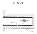
- the reason for this is that when filter regeneration starts, the PM accumulated on the filter is not burned off evenly over the entire filter (because the temperature distribution inside the filter is not even). As a result, PM accumulated on the filter is partially removed, so PM is combusted in such as way that a hole forms in part of the PM accumulation layer. When a hole forms in the PM accumulation layer (see FIG.
- the differential pressure of the pressures in front and in back of the filter abruptly decreases, which causes the PM accumulated amount that is estimated based on the differential pressure to become a lower value than the actual PM accumulated amount. Therefore, the estimated PM accumulated amount ends up falling equal to or below the end-regeneration determining value before the actual PM accumulated amount reaches the end-regeneration determining value, so filter regeneration ends even though there is still PM in the filter.
- the period (interval) until the PM accumulated amount estimated based on the differential pressure reaches the start-regeneration determining value becomes shorter, such that filter regeneration is executed more frequently which may reduce fuel efficiency. Also, if filter regeneration is executed more frequently and that filter regeneration is performed with a post injection, oil dilution (i.e., fuel mixed in with the engine oil) from that post injection will increase. If oil dilution increases, the oil film at the sliding portions of the engine may shear or the level of the engine oil may rise (causing the oil to run over).
- oil dilution i.e., fuel mixed in with the engine oil
- the process for estimating the PM amount based on the differential pressure may be selected. That is, if a PM combustion condition ceases to be satisfied due to, for example, the catalyst temperature not being high enough even if there is a filter regeneration command, the combustion mode will switch from the regeneration combustion mode to the normal combustion mode. If the combustion mode switches to the normal combustion mode, the process for estimating the PM amount based on the differential pressure may be selected. If the process for estimating the PM amount based on the differential pressure is selected when there is such a filter regeneration command, the problems described below may arise.
- the differential pressure of the pressures in front and in back of the filter i.e., the estimated PM accumulated amount
- the differential pressure of the pressures in front and in back of the filter i.e., the estimated PM accumulated amount
- the differential pressure of the pressures in front and in back of the filter will abruptly decrease when a hole forms in part of the PM accumulation layer from the filter regeneration.
- the combustion mode switches to the normal combustion mode during filter regeneration (at point X) such that a selection can be made between the process for estimating the PM amount based on the engine operating state and the process for estimating the PM amount based on the differential pressure
- the PM accumulated amount based on the differential pressure abruptly decreases, while the PM accumulated amount estimated based on the engine operating state rises when the combustion mode is the normal combustion mode.
- the filter ends up being in a filter regeneration complete state (a filter regeneration complete state as far as the control is concerned) when the PM accumulated amount based on the differential pressure decreases to the end-regeneration determining value. That is, it is determined that filter regeneration has been completed and filter regeneration ends even though there is still a large amount of PM remaining on the filter.
- the combustion mode is the normal combustion mode after it has been determined that regeneration has been completed in filter control
- the differential pressure of the pressures in front and in back of the filter abruptly rises when the hole is blocked by the accumulation of PM in the hole of the PM accumulation layer described above.
- the estimated PM accumulated amount quickly reaches the start-regeneration determining value, so filter regeneration starts.
- the combustion mode switches to the normal combustion mode during filter regeneration (when there is a filter regeneration command) such that there is a possibility that the process for estimating the PM amount based on the differential pressure will be selected
- the interval during which filter regeneration is executed becomes shorter, which reduces fuel efficiency.
- oil dilution i.e., fuel mixed in with the engine oil
- the combustion mode frequently switches to the normal combustion mode during filter regeneration when the vehicle continues to travel at a low speed, for example, so in this case, the frequency of filter regeneration increases so fuel efficiency decreases even more.
- the invention therefore provides an exhaust gas control apparatus capable of executing filter regeneration by oxidising and removing PM (particulate matter) that has accumulated on a particulate filter, and accurately determining when filter regeneration is complete.
- a first aspect of the invention presumes and relates to an exhaust gas control apparatus of an internal combustion engine, that is provided with a filter that is arranged in an exhaust passage of an internal combustion engine and traps particulate matter in exhaust gas, and filter regeneration controlling means for estimating an accumulated amount of particulate matter accumulated on the filter, starting filter regeneration to remove the particulate matter accumulated on the filter in response to a filter regeneration command when the estimated accumulated amount of particulate matter reaches a start-regeneration determining value, and ending the filter regeneration when the estimated accumulated amount of particulate matter decreases to an end-regeneration determining value.
- the filter regeneration controlling means determines that a period of time from after there is filter regeneration command and the filter regeneration starts until the filter regeneration has been completed, and which is a period of time during which the filter regeneration is not prohibited, is a period of time during which the filter is in a filter regeneration incomplete state.
- the filter regeneration controlling means estimates the accumulated amount of particulate matter accumulated on the filter based on the engine operating state while the filter is in the filter regeneration incomplete state.
- the accumulated amount of particulate matter accumulated on the filter is estimated based on the engine operating state, and the estimation process for estimating the PM accumulated amount based on the differential pressure of the pressures in front and in back of the filter is prevented from being selected while the filter is in the filter regeneration incomplete state, i.e., during a period of time from after there is filter regeneration command and the filter regeneration starts until the filter regeneration has been completed, and which is a period of time during which the filter regeneration is not prohibited.
- the PM accumulated amount is estimated based on the engine operating state even if the combustion mode switches to the normal combustion mode during that filter regeneration. Accordingly, the relationship between the estimated PM accumulated amount and the actual PM accumulated amount will not become skewed, thus making it is possible to accurately determine when filter regeneration has been completed. As a result, it is possible to suppress an increase in the frequency with which filter regeneration is executed, and thus suppress a reduction in fuel efficiency. Also, when filter regeneration is performed by a post injection, oil dilution from that post injection can be suppressed.
- the period of time during which the filter regeneration is not prohibited refers to a period of time during which a process for prohibiting the filter regeneration during a period of time until the fuel that is mixed in with the oil sufficiently vaporises, even if there is a filter regeneration command, after that maximum duration (i.e., the duration of the post injection at which the amount of fuel diluting the oil reaches the allowable limit) is reached, is not being performed.
- the engine In this filter regeneration prohibited state, the engine is in the normal combustion mode, PM newly accumulates on the filter, and the fuel that is mixed in with the engine oil vaporises (the oil recovers from being diluted), so the estimation process for estimating the PM accumulated amount based on the differential pressure is able to be selected.
- the filter regeneration controlling means may be able to select an estimation process for estimating the accumulated amount of particulate matter based on the engine operating state or an estimation process for estimating the accumulated amount of particulate matter based on a differential pressure of pressures in front and in back of the filter.
- the filter regeneration controlling means may be able to select an estimation process for estimating the accumulated amount of particulate matter based on the engine operating state or an estimation process for estimating the accumulated amount of particulate matter based on a differential pressure of pressures in front and in back of the filter.
- the filter regeneration controlling means may be able to select an estimation process for estimating the accumulated amount of particulate matter based on the engine operating state or an estimation process for estimating the accumulated amount of particulate matter based on a differential pressure of pressures in front and in back of the filter. Also, a filter regeneration command may be generated and filter regeneration may be started when one of the estimated PM accumulated amounts, from among the two estimated PM accumulated amounts estimated by these estimation processes, reaches a start-regeneration determining value.
- the filter regeneration is able to be ended at the appropriate timing, which makes it possible to suppress an increase in the frequency with which filter regeneration is executed, thus making it possible to suppress a reduction in fuel efficiency.
- a determination that the filter is in the filter regeneration incomplete state may be made when any one or more conditions, from among i) a condition that the number of times that the filter regeneration has been completed be greater than a predetermined determining number, ii) a condition the flowrate of exhaust gas that flows through the filter be greater than a predetermined flowrate, iii) a condition that there be no malfunction in the exhaust gas control apparatus, iv) a condition that an amount of change in the differential pressure of the pressures in front and in back of the filter be equal to or less than a predetermined amount, v) a condition that the exhaust gas control apparatus not be executing NO 2 reduction control, and vi) a condition that filter regeneration to remove particulate matter accumulated on the filter not be being executed, are satisfied.
- a determination that the filter is in the filter regeneration incomplete state may be made when any one or more conditions, from among i) a condition that the number of times that the filter regeneration has been completed be equal to or less than a predetermined determining number, ii) a condition the flowrate of exhaust gas that flows through the filter be equal to or less than a predetermined flowrate, iii) a condition that there be a malfunction in the exhaust gas control apparatus, iv) a condition that an amount of change in the differential pressure of the pressures in front and in back of the filter be greater than a predetermined amount, v) a condition that the exhaust gas control apparatus be executing NO 2 reduction control, and vi) a condition that filter regeneration to remove particulate matter (PM) accumulated on the filter be being executed, have not continued to be satisfied for a predetermined period of time or longer.
- a condition that the number of times that the filter regeneration has been completed be equal to or less than a predetermined determining number
- the filter regeneration controlling means may estimate the accumulated amount of particulate matter accumulated on the filter based on the engine operating state when any one or more conditions, from among i) a condition that the number of times that the filter regeneration has been completed be equal to or less than a predetermined determining number, ii) a condition the flowrate of exhaust gas that flows through the filter be equal to or less than a predetermined flowrate, iii) a condition that there be a malfunction in the exhaust gas control apparatus, iv) a condition that an amount of change in the differential pressure of the pressures in front and in back of the filter be greater than a predetermined amount, v) a condition that the exhaust gas control apparatus be executing NO 2 reduction control, and vi) a condition that filter regeneration to remove particulate matter accumulated on the filter be being executed, have continued to be satisfied for a predetermined period of time or longer.
- a diesel engine 1 (hereinafter simply referred to as "engine 1") according to this example embodiment is a common rail in-cylinder direct injection four cylinder engine, for example, in which an injector (i.e., a fuel injection valve) 2 is arranged in a combustion chamber la of each cylinder of the engine 1, and injects fuel for combustion in the combustion chamber la.
- the injector 2 of each cylinder is connected to a common rail 11, which is in turn connected to a supply pump 10.
- the supply pump 10 draws up fuel from a fuel tank and pressurises it before supplying it to the common rail 11 via a fuel line 10a.
- the common rail 11 functions as an accumulator that maintains (accumulates) the pressurised fuel supplied from the supply pump 10 at a predetermined pressure, and distributes this accumulated fuel to the injectors 2.
- Each injector 2 is an electromagnetically driven on-off valve that opens to inject (i.e., supply) fuel into the combustion chamber la when a predetermined voltage is applied.
- the opening and closing (i.e., the fuel injection quantity and the fuel injection timing) of the injectors 2 is duty-controlled by an ECU (Electronic Control Unit) 100.
- ECU Electronic Control Unit
- An intake passage 3 and an exhaust passage 4 are connected to the engine 1.
- An air cleaner 9, an airflow meter 33, a compressor impeller 63 of a turbocharger 6 that will be described later, an intercooler 8, and a throttle valve 5 are arranged, in order from upstream (i.e., the portion on the upstream side of the intake air flow) to downstream in the intake passage 3.
- the throttle opening amount of the throttle valve 5 is adjusted by a throttle motor 51.
- the throttle opening amount of the throttle valve 5 is detected by a throttle opening amount sensor 41.
- the intake passage 3 branches off to each cylinder at an intake manifold 3a that is arranged downstream of the throttle valve 5.
- the exhaust passage 4 is formed such that branches leading from the individual cylinders are all brought together by an exhaust manifold 4a that is connected to the combustion chamber la of each cylinder of the engine 1.
- a CCO (an oxidation catalytic converter) 21 that purifies HC (hydrocarbons) and CO (carbon monoxide) in the exhaust gas by purifying them, and a DPF 22 that traps PM (particulate matter) are arranged in order in the exhaust passage 4. Exhaust gas generated from combustion in the combustion cylinders la is sent into the exhaust passage 4.
- An A/F sensor 36 and a first exhaust gas temperature sensor 37 are arranged in the exhaust passage 4 upstream (on the upstream side of the exhaust gas flow) of the CCO 21.
- the temperature of the exhaust gas that enters the CCO 21 can be detected from the output signal of the first exhaust gas temperature sensor 37.
- a second exhaust gas temperature sensor 38 is arranged in the exhaust passage 4 between the CCO 21 and the DPF 22.
- the temperature of the exhaust gas that enters the DPF 22 i.e., the filter temperature (bed temperature)
- a differential pressure sensor 39 that detects the differential pressure between the pressure upstream of the DPF 22 and the pressure downstream of the DPF 22 is also provided.
- the output signals from the A/F sensor 36, the first exhaust gas temperature sensor 37, the second exhaust gas temperature sensor 38, and the differential pressure sensor 39 are input to the ECU 100.
- the engine 1 is provided with a turbocharger 6.
- This turbocharger 6 includes a turbine wheel 62 and a compressor impeller 63 that are coupled together via a rotor shaft 61.
- the compressor impeller 63 is arranged facing the inside of the intake passage 3, and the turbine wheel 62 is arranged facing the inside of the exhaust passage 4.
- This kind of turbocharger 6 supercharges the intake air by using the exhaust flow (i.e., exhaust pressure) on the turbine wheel 62 to rotate the compressor impeller 63.
- the turbocharger 6 in this example embodiment is a variable nozzle turbocharger, in which a variable nozzle vane mechanism 64 is provided on the turbine wheel 62 side, and the boost pressure of the engine 1 can be adjusted by adjusting the opening amount of this variable nozzle vane mechanism 64.
- the intake air that has been heated by the supercharging in the turbocharger 6 is forcibly cooled by the intercooler 8 arranged in the intake passage 3.
- the engine 1 is also provided with an EGR system 7.
- This EGR system 7 is a system that circulates some of the exhaust gas that flows through the exhaust passage 4 to the intake passage 3 and lowers the combustion temperature by supplying that recirculated exhaust gas into the combustion chambers la of the cylinders, thereby reducing the amount of NOx that is generated.
- the EGR system 7 includes an EGR passage 71 that connects the intake manifold 3a with the exhaust manifold 4a.
- An EGR cooler 73 for cooling the EGR gas that flows (is circulated) through the EGR passage 71, and an EGR valve 72 are provided, in order from the upstream side of the EGR gas flow, in the EGR passage 71.
- the amount of EGR gas i.e., the amount of recirculated exhaust gas introduced into the intake passage 3 (i.e., the intake manifold 3a) from the exhaust passage 4 (i.e., the exhaust manifold 4a) can be adjusted by adjusting the opening amount of this EGR valve 72.
- the ECU 100 includes a CPU 101, ROM 102, RAM 103, and backup RAM 104 and the like, as shown in FIG. 2 .
- ROM 102 Various control programmes and maps that are referenced when executing those various control programmes and the like are stored in the ROM 102.
- the CPU 101 performs calculations based on the various control programmes and maps stored in the ROM 102.
- the RAM 103 is memory that temporarily stores the calculation results of the CPU 101 and data and the like that has been input from various sensors
- the backup RAM 104 is non-volatile memory that stores data and the like that is to be saved when the engine 1 is stopped.
- the CPU 101, the ROM 102, the RAM 103, and the backup RAM 104 are all connected together, as well as to an input interface 105 and an output interface 106, via a bus 107.
- Various sensors are connected to the input interface 105. Some of these sensors include an engine speed sensor 31 that detects the rotation speed of a crankshaft that is an output shaft of the engine 1, a coolant temperature sensor 32 that detects the coolant temperature of the engine (i.e., the coolant temperature), the airflow meter 33, an intake air temperature sensor 34 that is arranged in the intake manifold 3a and detects the temperature of intake air, an intake air pressure sensor 35 that is arranged in the intake manifold 3a and detects the pressure of intake air, the A/F sensor 36, the first exhaust gas temperature sensor 37, the second exhaust gas temperature sensor 38, the differential pressure sensor 39, a rail pressure sensor 40 that detects the pressure of pressurised fuel in the common rail 11, a throttle opening amount sensor 41, an accelerator operation amount sensor 42, and a vehicle speed sensor 43. Signals from these sensors are input to the ECU 100.
- an engine speed sensor 31 that detects the rotation speed of a crankshaft that is an output shaft of the engine 1
- the injectors 2, the supply pump 10, the throttle motor 51 of the throttle valve 5, the variable nozzle vane mechanism 64 of the turbocharger 6, and the EGR valve 72 and the like are connected to the output interface 106.
- the ECU 100 executes various controls of the engine 1, including opening amount control of the throttle valve 5, and fuel injection quantity and injection timing control (i.e., opening / closing control of the injectors 2) of the engine 1, based on the output signals from the various sensors described above. Furthermore, the ECU 100 executes NO 2 reduction control, DPF regeneration control, a routine for determining the filter regeneration incomplete state, and control for selecting a process for estimating the PM amount.
- the ECU 100 also performs a malfunction diagnosis (i.e., a diagnosis) of the exhaust devices (such as the A/F sensor 36 and the differential pressure sensor 39).
- a malfunction diagnosis i.e., a diagnosis
- the exhaust devices such as the A/F sensor 36 and the differential pressure sensor 39.
- Control of the exhaust gas control apparatus of the invention may also be realised by a programme executed by the ECU 100 described above.
- the air-fuel ratio in most of the operating region is a lean air-fuel ratio, so during normal operation, the atmosphere around the CCO 21 has a high concentration of oxygen and the NO 2 (NOx) in the exhaust gas is absorbed by the CCO 21.
- the catalyst deteriorates from the thermal load and sulfur poisoning (S poisoning) and when the NO 2 reduction performance declines, it is necessary to reduce the NO 2 and recover the CCO 21.
- the ECU 100 executes NO 2 reduction control. More specifically, when the NO 2 storage amount estimated based on the engine operating state or the like reaches a predetermined limit value, the air-fuel ratio (A/F) of the exhaust gas is controlled by executing a post injection to supply fuel into the exhaust passage 4 upstream of the CCO 21. As a result, the temperature around the CCO 21 increases and a reduction atmosphere is created around the CCO 21 such that the NO 2 stored in the CCO 21 is reduced and released.
- A/F air-fuel ratio
- the PM regeneration control which will be described later, and the NO 2 reduction control are performed when there is a command to do so, but when the execution of these controls overlap, the PM regeneration control will be executed first and then the NO 2 reduction control will be executed, for example.
- the ECU 100 estimates the amount of accumulated PM by the two processes (1) and (2) below.
- an estimated amount of accumulated PM (also simply referred to as the "estimated PM accumulated amount”) PMs is calculated using the amount of generated PM (also simply referred to as the "PM generated amount”) pme and the amount of combusted PM (also simply referred to as the "PM combusted amount) pmc.
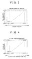
- the PM generated amount pme is the amount of PM that is discharged from all of the combustion chambers of the engine per unit of time (for example, during one control cycle of the estimating process). This PM generated amount pme is obtained referencing the map in FIG. 3 based on the engine speed NE obtained from the output signal from the engine speed sensor 31, and the fuel injection quantity Qv (a command value).
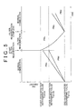
- the PM combusted amount pmc is the amount of PM accumulated on the DPF 22 that is oxidised and combusted per unit of time (for example, during one control cycle of the estimating process). This PM combusted amount pmc is obtained referencing the map in FIG. 4 (a PM oxidation rate map) based on the exhaust gas temperature Theg (which corresponds to the filter temperature) obtained from the output signal of the second exhaust gas temperature sensor 38, and the intake air amount Ga obtained from the output signal of the airflow meter 33.
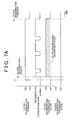
- the PMs (last value) when filter regeneration starts is a value that corresponds to a start-regeneration determining value Thpmss (see FIG. 5 ).
- the PMs (last value) when starting the normal combustion mode after the filter regeneration has been completed is an initial value of "0".
- the map shown in FIG. 3 is a map of the values of the PM generated amount pme obtained through testing and calculation or the like, with the engine speed NE and the fuel injection quantity Qv as parameters. This map is stored in the ROM 102 of the ECU 100. Incidentally, in the map shown in FIG. 3 , the PM generated amount pme is calculated by interpolation when the engine speed NE and the fuel injection quantity Qv are values that are between points on the map.
- the map shown in FIG. 4 is a map of the values of the PM combusted amount pmc obtained through testing and calculation or the like, with the exhaust gas temperature Theg and the intake air amount Ga as parameters. This map is also stored in the ROM 102 of the ECU 100. Incidentally, in the map shown in FIG. 4 , the PM combusted amount pmc is calculated by interpolation when the exhaust gas temperature Theg and the intake air amount Ga are values that are between points on the map.
- the amount of accumulated PM trapped in the DPF 22 (i.e., the estimated PM accumulated amount PMd) can be estimated referencing a map based on the differential pressure ⁇ P obtained from the output signal from the differential pressure sensor 39 provided in the exhaust passage 4 (i.e., the DPF 22).
- the map used to calculate the estimated PM accumulated amount is a map of compatible values obtained through testing and calculation or the like, taking into account the correlation between the differential pressure ⁇ P of the exhaust gas pressures in front and in back of the DPF 22 and the PM accumulated amount described above.
- This map is stored in the ROM 102 of the ECU 100.
- the ECU 100 estimates the estimated PM accumulated amount PMs and the estimated PM accumulated amount PMd by the processes described above, i.e., the process for estimating the PM amount based on the engine operating state and the process for estimating the PM amount based on the differential pressure.
- the estimated PM accumulated amount PMs and the estimated PM accumulated amount PMd increase over time.
- the ECU 100 determines whether the increasing estimated PM accumulated amount PMs has increased to a value at which a determination is made to start regeneration (also simply referred to as a "start-regeneration determining value"; this value corresponds to a limit PM accumulated amount) Thpmss, or the increasing estimated PM accumulated amount PMd has increased to a value at which a determination is made to start regeneration (also simply referred to as a "start-regeneration determining value”; this value corresponds to a limit PM accumulated amount) Thpmds (see FIG. 5 ).
- the ECU 100 determines that it is time to start regenerating the DPF 22 when the estimated PM accumulated amount PMs reaches the start-regeneration determining value Thpmss or the estimated PM accumulated amount PMd reaches the start-regeneration determining value Thpmds.
- both of the estimated PM accumulated amounts PMs and PMd are initialised (set to "0") when the estimated PM accumulated amount PMs reaches the start-regeneration determining value Thpmss or the estimated PM accumulated amount PMd reaches the start-regeneration determining value Thpmds.
- a CCO temperature-increasing fuel injection (a post injection) is executed after a main fuel injection (i.e., a main injection) that is a fuel injection performed to operate the engine (i.e., an injection of fuel into the combustion chambers la from the injectors 2).
- the fuel injected from the injectors 2 by this CCO temperature-increasing fuel injection is delivered into the exhaust passage 4 and reaches the CCO 21.
- the fuel component reaches the CCO 21
- an oxidation reaction takes place in the exhaust gas and on the catalyst with the components such as HC and CO and the like.
- This oxidation reaction generates heat which increases the temperature of the CCO 21 (i.e., the exhaust gas), which in turn causes the temperature of the DPF 22 to increase. Then after performing this kind of CCO temperature-increasing fuel injection, a DPF regeneration fuel injection is executed at a predetermined timing, which bums off the PM that has accumulated on the DPF 22, thereby reducing the amount of PM accumulated on the DPF 22.
- the CCO 21 i.e., the exhaust gas
- this estimated PM accumulated amount PMs has decreased to a value at which it is determined that regeneration is to end (also referred to as an "end-regeneration determining value") thpmse (see FIG. 5 )
- the ECU 100 determines that regeneration of the DPF 22 has been completed (i.e., filter regeneration complete) and filter regeneration ends.
- the initial value [PMs (last value)] of the estimated PM accumulated amount PMs during filter regeneration is a value that corresponds to the start-regeneration determining value Thpmss.
- filter regeneration is executed by the post injection, so oil dilution (i.e., fuel mixed into the engine oil) progresses with the injection of fuel from that post injection. Therefore, a limit is placed on the maximum duration of the filter regeneration. Once this maximum duration is reached, filter regeneration is prohibited (i.e., filter regeneration prohibited) until the fuel mixed into the oil sufficiently vaporises, even if there is still a command for filter regeneration.
- the ECU 100 includes a timer/counter. During filter regeneration (i.e., in a specific combustion mode that affects oil dilution), the ECU 100 counts the duration of filter regeneration using the timer/counter. When the count value of the filter regeneration duration reaches a maximum duration (i.e., the duration of the post injection at which the amount of fuel diluting the oil reaches the allowable limit), the ECU 100 prohibits filter regeneration for a fixed period of time.
- the period for which filter regeneration is prohibited is established by obtaining, through testing and calculation or the like, the period of time during which the fuel that is mixed in with the engine oil sufficiently vaporises (i.e., the time that it takes to recover from the oil dilution well enough for filter regeneration to be able to be executed), and setting a compatible value based on the results.
- this filter regeneration prohibited state it is possible to select the process for estimating the PM amount based on the differential pressure, as will be described later.
- the ECU 100 will switch the combustion mode of the engine 1 from the regeneration combustion mode to the normal combustion mode when the PM combustion condition ceases to be satisfied. More specifically, when the engine has been idling or the vehicle has been running at a low speed for an extended period of time, for example, the CCO 21 does not heat up so even if a post injection is executed, the filter temperature will not increase sufficiently, making it difficult to combust PM. In this case, it is determined that the PM combustion condition is not satisfied, so the ECU 100 switches the combustion mode from the regeneration combustion mode to the normal combustion mode.
- the ECU 100 will determine that the filter is in the filter regeneration incomplete state until filter regeneration has been completed, so the ECU 100 will not select the process for estimating the PM amount based on the differential pressure, but instead estimate the estimated PM accumulated amount PMs using the process for estimating the PM amount based on the engine operating state.
- a specific example is given below.
- the routine for determining whether the filter is in the filter regeneration incomplete state will be described with reference to the flowchart in FIG. 6 .
- the routine in FIG. 6 is executed repeatedly in predetermined cycles (such as approximately every several milliseconds to every several tens of milliseconds) in the ECU 100.
- step ST101 the ECU 100 determines whether the filter regeneration has been completed (i.e., filter regeneration complete) based on the current PM accumulated amount PMs estimated according to the process for estimating the PM amount based on the engine operating state described above. If the determination is yes, the ECU 100 determines that the current PM accumulation state of the DPF 22 is a filter regeneration complete state (step ST105). If the determination in step ST101 is no (i.e., if the filter is not in the filter regeneration complete state), the process proceeds on to step ST102.
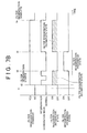
- step ST102 the ECU 100 determines whether there is a filter regeneration command. More specifically, a filter regeneration command is generated when the estimated PM accumulated amount PMs reaches the start-regeneration determining value Thpmss or the estimated PM accumulated amount PMd reaches the start-regeneration determining value Thpmds. If this filter regeneration command generated, the process proceeds on to step ST103. Incidentally, the filter regeneration command continues (i.e., a command flag continues to be raised) until filter regeneration is complete, as shown in FIG. 7 .
- step ST102 If the determination in step ST102 is no, the process returns.
- step ST103 the ECU 100 determines whether the current state is the filter regeneration prohibited state. If this determination is no, the ECU 100 determines that the current is the filter regeneration incomplete state (step ST104).
- step ST103 If the determination in step ST103 is yes (i.e., if the current state is the filter regeneration prohibited state), the process returns. That is, when the current state is the filter regeneration prohibited state, PM accumulates on the DPF 22 and the fuel that is mixed in with the engine oil vaporises (the oil recovers from being diluted) in this filter regeneration prohibited state, so the ECU 100 does not make a determination that the filter is in the filter regeneration incomplete state.
- filter regeneration starts in response to that regeneration command. Then at time t2 when filter regeneration starts, the filter regeneration incomplete state turns on. This filter regeneration incomplete state continues until time tn, at which time filter regeneration is complete, as long as the filter regeneration prohibited state does not turn on.
- the filter regeneration incomplete state continues even when the combustion mode of the engine 1 switches from the regeneration combustion mode to the normal combustion mode. Therefore, the estimated PM accumulated amount PMs is estimated using the process for estimating the PM amount based on the engine operating state. This will be described later.
- FIG. 7A shows that after filter regeneration starts (i.e., while the filter is in the filter regeneration incomplete state), the filter regeneration incomplete state continues even when the combustion mode of the engine 1 switches from the regeneration combustion mode to the normal combustion mode. Therefore, the estimated PM accumulated amount PMs is estimated using the process for estimating the PM amount based on the engine operating state. This will be described later.
- the filter regeneration prohibited state turns on between time t2 when filter regeneration starts and time tn when filter regeneration is complete, then during this filter regeneration prohibited state (i.e., from t3 to t4), the filter regeneration incomplete state will turn off and the combustion mode will switch to the normal combustion mode such that the process for estimating the PM accumulated amount based on the differential pressure may be selected. This will also be described later.
- the filter regeneration incomplete state is a state in which there is a filter regeneration command, during a period after filter regeneration starts until filter regeneration has been completed and filter regeneration is not being prohibited.
- the routine in FIG. 8A and FIG. 8B is executed repeatedly in predetermined cycles (such as approximately every several milliseconds to every several tens of milliseconds) in the ECU 100.
- step ST201 the ECU 100 determines whether the number of times the filter regeneration has been completed is equal to or less than a predetermined determining value. If the determination is yes, the process proceeds on to step ST207. If, on the other hand, the determination in step ST201 is no, the ECU 100 determines that the DPF 22 is new and the process proceeds on to step ST202.
- the reason for providing step ST201 is because when the DPF 22 is new, the accuracy of the process for estimating the PM amount based on the differential pressure is low, so step ST201 is provided so that that process for estimating the PM amount will not be selected.
- the determining value used in the determination of step ST201 is set by obtaining, through testing and calculation or the like, the number of times that the accuracy of the process for estimating the PM amount based on the differential pressure falls within an allowable range (i.e., the number of times filter regeneration has been completed), and setting a compatible value based on the results.
- step ST202 the ECU 100 determines whether the exhaust gas flowrate is equal to or less than a predetermined determining value. If this determination is yes, the process proceeds on to step ST207. If, on the other hand, the determination in step ST202 is no, the process proceeds on to step ST203.
- the reason for providing step ST202 is because when the exhaust gas flowrate is low, the accuracy of the process for estimating the PM amount based on the differential pressure is low, so step ST202 is provided so that that process for estimating the PM amount will not be selected.
- the exhaust gas flowrate may be calculated based on, for example, the engine speed NE that can be obtained from the output signal of the engine speed sensor 31, the fuel injection quantity Qv (i.e., a command signal), and the intake air amount Ga that can be obtained from the output signal of the airflow meter 33.
- an exhaust gas flowrate sensor may also be arranged in the exhaust passage 4 and the exhaust gas flowrate obtained from the output signal of that sensor.
- the determining value used in the determination of step ST202 is set by obtaining, through testing and calculation or the like, the exhaust gas flowrate at which the accuracy of the process for estimating the PM amount based on the differential pressure falls outside of the allowable range, and setting a compatible value based on the results.
- step ST203 the ECU 100 performs a malfunction diagnosis of the exhaust devices (such as the A/F sensor 36 and the differential pressure sensor 39) and determines whether those exhaust devices are malfunctioning. If the determination in step ST203 is yes, the ECU 100 determines that the process for estimating the PM amount based on the differential pressure is unreliable and the process proceeds on to step ST207. If, on the other hand, the determination in step ST203 is no, the process proceeds on to step ST204.
- the exhaust devices such as the A/F sensor 36 and the differential pressure sensor 39
- step ST204 the ECU 100 determines whether the amount of change in the differential pressure ⁇ P of the pressures in front and in back of the DPF 22 (i.e., the amount of change per unit time) is greater than a predetermined determining value. If this determination is yes, the process proceeds on to step ST207. If, on the other hand, the determination in step ST204 is no, the process proceeds on to step ST205.
- step ST204 is executed so that the process for estimating the PM amount based on the differential pressure will not be selected when the amount of change in the differential pressure ⁇ P of the pressures in front and in back of the DPF 22 is large.
- the determining value used in the determination of step ST204 is set by, for example, obtaining, through testing and calculation or the like, the maximum value for the amount of change per unit time of the differential pressure ⁇ P from the PM accumulated on the DPF 22, and applying a value that enables a distinction to be made between a change in the differential pressure from PM accumulation and an abrupt change in the differential pressure due to some other reason, based on the results.
- step ST205 the ECU 100 determines whether the NO 2 reduction control is currently being executed. If the determination is yes, the process proceeds on to step ST207. If, on the other hand, the determination in step ST205 is no, the process proceeds on to step ST206.
- the reason for providing step ST205 is because when NO 2 reduction control is being executed, the holes described above (i.e., holes in the PM accumulation layer) tend to form which causes the process for estimating the PM amount based on the differential pressure to become unreliable, so step ST205 is provided so that that process for estimating the PM amount will not be selected.
- step ST206 the ECU 100 determines whether the combustion mode is a specific combustion mode (being either a combustion mode for increasing the bed temperature of the CCO 21 or a filter regeneration combustion mode). If the determination is yes, the process proceeds on to step ST207. If, on the other hand, the determination in step ST206 is no (i.e., if the combustion mode is the normal combustion mode), the process proceeds on to step ST208.
- Step ST206 is a step that is performed so that the process for estimating the PM amount based on the differential pressure will not be selected during filter regeneration.
- Step ST207 is a step that is performed to remove noise and the like. In this step, it is determined whether the determining condition of any one of steps ST201 to ST206 has remained satisfied for a fixed period of time or longer. If the determination is yes, the ECU 100 selects the process for estimating the PM amount based on the engine operating state (step ST209), and estimates the PM accumulated amount using that selected PM amount estimation process. If, on the other hand, the determination in step ST207 is no, the process proceeds on to step ST208.
- step ST208 the ECU 100 determines whether the current state is the filter regeneration incomplete state based on the determination in FIG. 6 . If the determination in step ST208 is yes, the ECU 100 selects the process for estimating the PM amount based on the engine operating state (step ST209), and estimates the PM accumulated amount using that selected PM amount estimation process.
- step ST208 determines whether the current state is not the filter regeneration incomplete state. If, on the other hand, the determination in step ST208 is no (i.e., if the current state is not the filter regeneration incomplete state), the ECU 100 is able to select the process for estimating the PM amount based on the differential pressure (step ST210), such that either the process for estimating the PM amount based on the engine operating state or the process for estimating the PM amount based on the differential pressure can be selected.
- the ECU 100 determines that a period of time from after there is a command to regenerate the filter and the filter regeneration starts until the filter regeneration has been completed, and which is a period of time during which the filter regeneration is not prohibited, is a period of time during which the filter is in a filter regeneration incomplete state. While the filter is in the filter regeneration incomplete state, the ECU 100 estimates the PM accumulation amount using the process for estimating the PM amount that is based on the engine operating state and prevents the process for selecting the PM amount that is based on the differential pressure from being selected.
- the PM accumulation amount continues to be estimated using the process for estimating the PM amount based on the engine operating state even if the combustion mode switches to the normal combustion mode while the filter is being regenerated. Accordingly, the relationship between the estimated PM accumulated amount and the actual PM accumulated amount will not become skewed, thus making it is possible to accurately determine when filter regeneration has been completed. As a result, it is possible to suppress an increase in the frequency with which filter regeneration is executed, and thus suppress a reduction in fuel efficiency. Also, oil dilution from the post injection can also be suppressed.
- the initial value [PMs (last value)] when calculating the estimated PM accumulated amount PMs during filter regeneration [PMs ⁇ PMs (last value) + pme - pmc] may be a constant value or it may be variably set according to the running state of the vehicle or the operating state of the engine 1.
- the exhaust gas temperature is higher, which facilitates regeneration of the DPF 22, when the vehicle speed is higher than when it is lower.
- the initial value of the estimated PM accumulated amount may therefore also be set variably according to the vehicle speed.
- the initial value of the estimated PM accumulated amount PMs during filter regeneration may also be set according to the exhaust gas flowrate, such that the initial value becomes larger as the exhaust gas flowrate decreases.
- the accuracy of the determination to end regeneration increases as the end-regeneration determining value Thpmse (see FIG. 5 ) that is set with for the estimated PM accumulated amount PMs during filter regeneration approaches "0".
- the end-regeneration determining value Thpmse becomes too close to "0"
- the filter regeneration time increases which may lead to lower fuel efficiency. Therefore, taking this determination accuracy and fuel efficiency into account, a compatible value obtained through testing and calculation or the like is set as the end-regeneration determining value Thpmse.
- filter regeneration is performed by the post injection after the main fuel injection, but the invention is not limited to this.
- filter regeneration may also be performed by adding fuel from a fuel adding valve in the exhaust passage (such as in the exhaust manifold 4a) upstream of the DPF 22.
- filter regeneration may be performed by a combination of added fuel and the post injection.
- the DPF is used as the particulate filter, but the invention is not limited to this. That is, the invention may also be applied to an exhaust gas control apparatus that uses a DPNR catalyst.
- the exhaust gas control apparatus of the invention is applied to an in-cylinder direct injection four cylinder diesel engine, but the invention is not limited to this.
- the invention may also be applied to a diesel engine with an arbitrary number of cylinders, such as an in-cylinder direct injection six cylinder diesel engine.
- the exhaust gas control apparatus of the example embodiment described above may also be applied to a lean-burn petrol engine in which the operating range where the engine is operated by supplying a mixture with a high air-fuel ratio (i.e., a lean atmosphere) accounts for the majority of the entire operating range.
- the invention is not limited to being applied to an engine of a vehicle, but may also be applied to an engine used for another purpose.
Landscapes
- Engineering & Computer Science (AREA)
- Chemical & Material Sciences (AREA)
- Combustion & Propulsion (AREA)
- Mechanical Engineering (AREA)
- General Engineering & Computer Science (AREA)
- Chemical Kinetics & Catalysis (AREA)
- Processes For Solid Components From Exhaust (AREA)
- Exhaust Gas Treatment By Means Of Catalyst (AREA)
Abstract
Description
- The invention relates to an exhaust gas control apparatus that purifies exhaust gas from an internal combustion engine (hereinafter also simply referred to as "engine"). More particularly, the invention relates to an internal combustion engine exhaust gas control apparatus that purifies exhaust gas from a diesel engine using a particulate filter.
- Exhaust gas that is discharged when driving an internal combustion engine such as a petrol engine or a diesel engine contains matter that is not desirable to discharge into the atmosphere as it is. In particular, exhaust gas from a diesel engine contains particulate matter (hereinafter also simply referred to as "PM") of which carbon is the main component, soot, and soluble organic fraction (SOF), and the like, all of which cause air pollution.
- One known apparatus that purifies PM in exhaust gas is an exhaust gas control apparatus that reduces the amount of emissions discharged into the atmosphere by providing a particulate filter in an exhaust passage of a diesel engine and trapping PM in exhaust gas that passes through the exhaust passage. DPFs (Diesel Particulate Filters) and DPNR (Diesel Particulate-NOx Reduction system) catalysts, for example, are used as particulate filters.
- When trapping PM using a particulate filter (hereinafter also simply referred to as "filter"), the filter will become clogged when a large amount of trapped PM has accumulated. When this happens, pressure loss of the exhaust gas that passes through the filter increases, which causes the exhaust gas back pressure in the engine to increase. As a result, engine output and fuel efficiency both decrease.
- To solve this problem, when the trapped amount (i.e., accumulated amount) of PM that has been trapped by the filter reaches a predetermined amount, the filter is regenerated by oxidising (burning off) the PM on the filter by increasing the catalyst bed temperature. More specifically, the filter is regenerated, for example, by increasing the temperature (i.e., the exhaust gas temperature) of an oxidation catalyst (CCO) upstream of the filter (i.e., on the upstream side of the exhaust gas flow) by additionally injecting a small amount of fuel (in a post injection) after a main fuel injection (a main injection), and then oxidising (burning off) the PM that has accumulated on the filter by executing a filter regenerating post injection (see Japanese Patent Application Publication No.
2008-202573 JP-A-2008-202573 - With this kind of filter regeneration control (hereinafter also referred to as "filter regeneration"), the amount of PM accumulated on the filter is estimated, and when that estimated PM accumulated amount reaches a predetermined value, it is determined that it is time to regenerate the filter and filter regeneration is executed (see Japanese Patent Application Publication No.
2008-202573 JP-A-2008-202573 JP-A-2004-218508 JP-A-2004-218508 - One way to estimate the PM accumulated amount is to provide a differential pressure sensor that detects the differential pressure between the pressure upstream of the filter and the pressure downstream of the filter (i.e., the differential pressure of the pressures in front and in back of the filter), and estimating the PM accumulated amount from the output signal of that differential pressure sensor (this estimation process will be referred to as the process for estimating the PM amount based on the differential pressure) (see
JP-A-2004-218508 JP-A-2008-202573 - When the estimated PM accumulated amount estimated by one of these two estimation processes reaches a start-regeneration determining value (which is a value that corresponds to a limit accumulation amount), filter regeneration control starts. For example, control is performed that ends filter regeneration when the PM accumulated amount estimated based on the engine operating state falls to an end-regeneration determining value. Incidentally, the reason for performing the two estimation processes, i.e., the process for estimating the PM amount based on the engine operating state and the process for estimating the PM amount based on the differential pressure, is to increase the reliability of the determination to start filter regeneration.
- Incidentally, the problem with process for estimating the PM amount based on the differential pressure is that the accuracy during filter regeneration is low and the estimated PM accumulated amount is a lower value than the actual PM accumulated amount. The reason for this is that when filter regeneration starts, the PM accumulated on the filter is not burned off evenly over the entire filter (because the temperature distribution inside the filter is not even). As a result, PM accumulated on the filter is partially removed, so PM is combusted in such as way that a hole forms in part of the PM accumulation layer. When a hole forms in the PM accumulation layer (see
FIG. 9 , for example), the differential pressure of the pressures in front and in back of the filter abruptly decreases, which causes the PM accumulated amount that is estimated based on the differential pressure to become a lower value than the actual PM accumulated amount. Therefore, the estimated PM accumulated amount ends up falling equal to or below the end-regeneration determining value before the actual PM accumulated amount reaches the end-regeneration determining value, so filter regeneration ends even though there is still PM in the filter. - In such a condition, the period (interval) until the PM accumulated amount estimated based on the differential pressure reaches the start-regeneration determining value becomes shorter, such that filter regeneration is executed more frequently which may reduce fuel efficiency. Also, if filter regeneration is executed more frequently and that filter regeneration is performed with a post injection, oil dilution (i.e., fuel mixed in with the engine oil) from that post injection will increase. If oil dilution increases, the oil film at the sliding portions of the engine may shear or the level of the engine oil may rise (causing the oil to run over).
- One way to solve these problems is simply to not select the process for estimating the PM amount based on the differential pressure during filter regeneration. However, when there is a filter regeneration command, the process for estimating the PM amount based on the differential pressure may be selected. That is, if a PM combustion condition ceases to be satisfied due to, for example, the catalyst temperature not being high enough even if there is a filter regeneration command, the combustion mode will switch from the regeneration combustion mode to the normal combustion mode. If the combustion mode switches to the normal combustion mode, the process for estimating the PM amount based on the differential pressure may be selected. If the process for estimating the PM amount based on the differential pressure is selected when there is such a filter regeneration command, the problems described below may arise.
- First, as described above, with the process for estimating the PM amount based on the differential pressure, the differential pressure of the pressures in front and in back of the filter (i.e., the estimated PM accumulated amount) will abruptly decrease when a hole forms in part of the PM accumulation layer from the filter regeneration. Here, as shown in
FIG. 10 , for example, when the combustion mode switches to the normal combustion mode during filter regeneration (at point X) such that a selection can be made between the process for estimating the PM amount based on the engine operating state and the process for estimating the PM amount based on the differential pressure, the PM accumulated amount based on the differential pressure abruptly decreases, while the PM accumulated amount estimated based on the engine operating state rises when the combustion mode is the normal combustion mode. Therefore, the filter ends up being in a filter regeneration complete state (a filter regeneration complete state as far as the control is concerned) when the PM accumulated amount based on the differential pressure decreases to the end-regeneration determining value. That is, it is determined that filter regeneration has been completed and filter regeneration ends even though there is still a large amount of PM remaining on the filter. When the combustion mode is the normal combustion mode after it has been determined that regeneration has been completed in filter control, the differential pressure of the pressures in front and in back of the filter abruptly rises when the hole is blocked by the accumulation of PM in the hole of the PM accumulation layer described above. As a result, the estimated PM accumulated amount quickly reaches the start-regeneration determining value, so filter regeneration starts. - In this way, when the combustion mode switches to the normal combustion mode during filter regeneration (when there is a filter regeneration command) such that there is a possibility that the process for estimating the PM amount based on the differential pressure will be selected, the interval during which filter regeneration is executed becomes shorter, which reduces fuel efficiency. Also, if the frequency with which filter regeneration is executed increases and that filter regeneration is performed by a post injection, oil dilution (i.e., fuel mixed in with the engine oil) from that post injection will increase. Further, the combustion mode frequently switches to the normal combustion mode during filter regeneration when the vehicle continues to travel at a low speed, for example, so in this case, the frequency of filter regeneration increases so fuel efficiency decreases even more.
- The invention therefore provides an exhaust gas control apparatus capable of executing filter regeneration by oxidising and removing PM (particulate matter) that has accumulated on a particulate filter, and accurately determining when filter regeneration is complete.
- A first aspect of the invention presumes and relates to an exhaust gas control apparatus of an internal combustion engine, that is provided with a filter that is arranged in an exhaust passage of an internal combustion engine and traps particulate matter in exhaust gas, and filter regeneration controlling means for estimating an accumulated amount of particulate matter accumulated on the filter, starting filter regeneration to remove the particulate matter accumulated on the filter in response to a filter regeneration command when the estimated accumulated amount of particulate matter reaches a start-regeneration determining value, and ending the filter regeneration when the estimated accumulated amount of particulate matter decreases to an end-regeneration determining value. The filter regeneration controlling means determines that a period of time from after there is filter regeneration command and the filter regeneration starts until the filter regeneration has been completed, and which is a period of time during which the filter regeneration is not prohibited, is a period of time during which the filter is in a filter regeneration incomplete state. The filter regeneration controlling means estimates the accumulated amount of particulate matter accumulated on the filter based on the engine operating state while the filter is in the filter regeneration incomplete state.
- According to this aspect, the accumulated amount of particulate matter accumulated on the filter is estimated based on the engine operating state, and the estimation process for estimating the PM accumulated amount based on the differential pressure of the pressures in front and in back of the filter is prevented from being selected while the filter is in the filter regeneration incomplete state, i.e., during a period of time from after there is filter regeneration command and the filter regeneration starts until the filter regeneration has been completed, and which is a period of time during which the filter regeneration is not prohibited.
- According to this aspect, after filter regeneration starts in response to a filter regeneration command, the PM accumulated amount is estimated based on the engine operating state even if the combustion mode switches to the normal combustion mode during that filter regeneration. Accordingly, the relationship between the estimated PM accumulated amount and the actual PM accumulated amount will not become skewed, thus making it is possible to accurately determine when filter regeneration has been completed. As a result, it is possible to suppress an increase in the frequency with which filter regeneration is executed, and thus suppress a reduction in fuel efficiency. Also, when filter regeneration is performed by a post injection, oil dilution from that post injection can be suppressed.
- When filter regeneration is executed by a post injection, the oil becomes increasingly diluted by the fuel from the post injection, so a limit is placed on the maximum duration of filter regeneration. Thus, the period of time during which the filter regeneration is not prohibited refers to a period of time during which a process for prohibiting the filter regeneration during a period of time until the fuel that is mixed in with the oil sufficiently vaporises, even if there is a filter regeneration command, after that maximum duration (i.e., the duration of the post injection at which the amount of fuel diluting the oil reaches the allowable limit) is reached, is not being performed. In this filter regeneration prohibited state, the engine is in the normal combustion mode, PM newly accumulates on the filter, and the fuel that is mixed in with the engine oil vaporises (the oil recovers from being diluted), so the estimation process for estimating the PM accumulated amount based on the differential pressure is able to be selected.
- In the foregoing aspect, when filter regeneration is not prohibited, the filter regeneration controlling means may be able to select an estimation process for estimating the accumulated amount of particulate matter based on the engine operating state or an estimation process for estimating the accumulated amount of particulate matter based on a differential pressure of pressures in front and in back of the filter.
- In the structure described above, when the filter is not in the filter regeneration incomplete state, the filter regeneration controlling means may be able to select an estimation process for estimating the accumulated amount of particulate matter based on the engine operating state or an estimation process for estimating the accumulated amount of particulate matter based on a differential pressure of pressures in front and in back of the filter.
- In the structure described above, when there is no command to regenerate the filter, the filter regeneration controlling means may be able to select an estimation process for estimating the accumulated amount of particulate matter based on the engine operating state or an estimation process for estimating the accumulated amount of particulate matter based on a differential pressure of pressures in front and in back of the filter. Also, a filter regeneration command may be generated and filter regeneration may be started when one of the estimated PM accumulated amounts, from among the two estimated PM accumulated amounts estimated by these estimation processes, reaches a start-regeneration determining value.
- According to this structure, in an exhaust gas control apparatus that executes filter regeneration to oxidise and remove particulate matter (PM) accumulated on a filter, the filter regeneration is able to be ended at the appropriate timing, which makes it possible to suppress an increase in the frequency with which filter regeneration is executed, thus making it possible to suppress a reduction in fuel efficiency.
- In the structure described above, a determination that the filter is in the filter regeneration incomplete state may be made when any one or more conditions, from among i) a condition that the number of times that the filter regeneration has been completed be greater than a predetermined determining number, ii) a condition the flowrate of exhaust gas that flows through the filter be greater than a predetermined flowrate, iii) a condition that there be no malfunction in the exhaust gas control apparatus, iv) a condition that an amount of change in the differential pressure of the pressures in front and in back of the filter be equal to or less than a predetermined amount, v) a condition that the exhaust gas control apparatus not be executing NO2 reduction control, and vi) a condition that filter regeneration to remove particulate matter accumulated on the filter not be being executed, are satisfied.
- In the structure described above, a determination that the filter is in the filter regeneration incomplete state may be made when any one or more conditions, from among i) a condition that the number of times that the filter regeneration has been completed be equal to or less than a predetermined determining number, ii) a condition the flowrate of exhaust gas that flows through the filter be equal to or less than a predetermined flowrate, iii) a condition that there be a malfunction in the exhaust gas control apparatus, iv) a condition that an amount of change in the differential pressure of the pressures in front and in back of the filter be greater than a predetermined amount, v) a condition that the exhaust gas control apparatus be executing NO2 reduction control, and vi) a condition that filter regeneration to remove particulate matter (PM) accumulated on the filter be being executed, have not continued to be satisfied for a predetermined period of time or longer.
- In the structure described above, the filter regeneration controlling means may estimate the accumulated amount of particulate matter accumulated on the filter based on the engine operating state when any one or more conditions, from among i) a condition that the number of times that the filter regeneration has been completed be equal to or less than a predetermined determining number, ii) a condition the flowrate of exhaust gas that flows through the filter be equal to or less than a predetermined flowrate, iii) a condition that there be a malfunction in the exhaust gas control apparatus, iv) a condition that an amount of change in the differential pressure of the pressures in front and in back of the filter be greater than a predetermined amount, v) a condition that the exhaust gas control apparatus be executing NO2 reduction control, and vi) a condition that filter regeneration to remove particulate matter accumulated on the filter be being executed, have continued to be satisfied for a predetermined period of time or longer.
- The foregoing and further objects, features and advantages of the invention will become apparent from the following description of preferred embodiments with reference to the accompanying drawings, wherein like numerals are used to represent like elements and wherein:
-
FIG. 1 is a block diagram schematically showing an example of a diesel engine to which the invention is applied; -
FIG. 2 is a block diagram of the structure of a control system including an ECU and the like; -
FIG. 3 is a view of a map for obtaining a PM generated amount pme; -
FIG. 4 is a view of a map for obtaining a PM combusted amount pmc; -
FIG. 5 is a timing chart showing a change in an estimated PM accumulated amount PMs that is estimated based on the engine operating state, and a change in an estimated PM accumulated amount PMd that is estimated based on differential pressure; -
FIG. 6 is a flowchart illustrating a routine for determining a filter regeneration incomplete state; -
FIG. 7A and7B are timing charts showing the period of the filter regeneration incomplete state; -
FIG. 8A andFIG. 8B are a flowchart illustrating a control routine for selecting the process for estimating the PM amount; -
FIG. 9 is a longitudinal sectional view showing a frame format of a main portion where a hole has formed in a PM accumulation layer during filter regeneration; and -
FIG. 10 is a chart illustrating a problem that occurs when the combustion mode switches to the normal combustion mode during filter regeneration. - An example embodiment of the present invention will be described in greater detail below with reference to the accompanying drawings.
- The general structure of a diesel engine to which the invention is applied will now be described with reference to
FIG. 1 . - A diesel engine 1 (hereinafter simply referred to as "
engine 1") according to this example embodiment is a common rail in-cylinder direct injection four cylinder engine, for example, in which an injector (i.e., a fuel injection valve) 2 is arranged in a combustion chamber la of each cylinder of theengine 1, and injects fuel for combustion in the combustion chamber la. Theinjector 2 of each cylinder is connected to acommon rail 11, which is in turn connected to asupply pump 10. - The
supply pump 10 draws up fuel from a fuel tank and pressurises it before supplying it to thecommon rail 11 via afuel line 10a. Thecommon rail 11 functions as an accumulator that maintains (accumulates) the pressurised fuel supplied from thesupply pump 10 at a predetermined pressure, and distributes this accumulated fuel to theinjectors 2. Eachinjector 2 is an electromagnetically driven on-off valve that opens to inject (i.e., supply) fuel into the combustion chamber la when a predetermined voltage is applied. The opening and closing (i.e., the fuel injection quantity and the fuel injection timing) of theinjectors 2 is duty-controlled by an ECU (Electronic Control Unit) 100. - An
intake passage 3 and anexhaust passage 4 are connected to theengine 1. Anair cleaner 9, anairflow meter 33, acompressor impeller 63 of aturbocharger 6 that will be described later, anintercooler 8, and a throttle valve 5 are arranged, in order from upstream (i.e., the portion on the upstream side of the intake air flow) to downstream in theintake passage 3. The throttle opening amount of the throttle valve 5 is adjusted by athrottle motor 51. The throttle opening amount of the throttle valve 5 is detected by a throttleopening amount sensor 41. Incidentally, theintake passage 3 branches off to each cylinder at anintake manifold 3a that is arranged downstream of the throttle valve 5. - The
exhaust passage 4 is formed such that branches leading from the individual cylinders are all brought together by anexhaust manifold 4a that is connected to the combustion chamber la of each cylinder of theengine 1. - A CCO (an oxidation catalytic converter) 21 that purifies HC (hydrocarbons) and CO (carbon monoxide) in the exhaust gas by purifying them, and a
DPF 22 that traps PM (particulate matter) are arranged in order in theexhaust passage 4. Exhaust gas generated from combustion in the combustion cylinders la is sent into theexhaust passage 4. - An A/
F sensor 36 and a first exhaustgas temperature sensor 37 are arranged in theexhaust passage 4 upstream (on the upstream side of the exhaust gas flow) of theCCO 21. The temperature of the exhaust gas that enters theCCO 21 can be detected from the output signal of the first exhaustgas temperature sensor 37. Also, a second exhaustgas temperature sensor 38 is arranged in theexhaust passage 4 between theCCO 21 and theDPF 22. The temperature of the exhaust gas that enters the DPF 22 (i.e., the filter temperature (bed temperature)) can be detected from the output signal of the second exhaustgas temperature sensor 38. Moreover, adifferential pressure sensor 39 that detects the differential pressure between the pressure upstream of theDPF 22 and the pressure downstream of theDPF 22 is also provided. - The output signals from the A/
F sensor 36, the first exhaustgas temperature sensor 37, the second exhaustgas temperature sensor 38, and thedifferential pressure sensor 39 are input to theECU 100. - The
engine 1 is provided with aturbocharger 6. Thisturbocharger 6 includes aturbine wheel 62 and acompressor impeller 63 that are coupled together via arotor shaft 61. - The
compressor impeller 63 is arranged facing the inside of theintake passage 3, and theturbine wheel 62 is arranged facing the inside of theexhaust passage 4. This kind ofturbocharger 6 supercharges the intake air by using the exhaust flow (i.e., exhaust pressure) on theturbine wheel 62 to rotate thecompressor impeller 63. Theturbocharger 6 in this example embodiment is a variable nozzle turbocharger, in which a variablenozzle vane mechanism 64 is provided on theturbine wheel 62 side, and the boost pressure of theengine 1 can be adjusted by adjusting the opening amount of this variablenozzle vane mechanism 64. Incidentally, the intake air that has been heated by the supercharging in theturbocharger 6 is forcibly cooled by theintercooler 8 arranged in theintake passage 3. - The
engine 1 is also provided with an EGR system 7. This EGR system 7 is a system that circulates some of the exhaust gas that flows through theexhaust passage 4 to theintake passage 3 and lowers the combustion temperature by supplying that recirculated exhaust gas into the combustion chambers la of the cylinders, thereby reducing the amount of NOx that is generated. The EGR system 7 includes anEGR passage 71 that connects theintake manifold 3a with theexhaust manifold 4a. AnEGR cooler 73 for cooling the EGR gas that flows (is circulated) through theEGR passage 71, and anEGR valve 72 are provided, in order from the upstream side of the EGR gas flow, in theEGR passage 71. The amount of EGR gas (i.e., the amount of recirculated exhaust gas) introduced into the intake passage 3 (i.e., theintake manifold 3a) from the exhaust passage 4 (i.e., theexhaust manifold 4a) can be adjusted by adjusting the opening amount of thisEGR valve 72. - The
ECU 100 includes aCPU 101,ROM 102,RAM 103, andbackup RAM 104 and the like, as shown inFIG. 2 . - Various control programmes and maps that are referenced when executing those various control programmes and the like are stored in the
ROM 102. TheCPU 101 performs calculations based on the various control programmes and maps stored in theROM 102. Also, theRAM 103 is memory that temporarily stores the calculation results of theCPU 101 and data and the like that has been input from various sensors, and thebackup RAM 104 is non-volatile memory that stores data and the like that is to be saved when theengine 1 is stopped. - The
CPU 101, theROM 102, theRAM 103, and thebackup RAM 104 are all connected together, as well as to an input interface 105 and anoutput interface 106, via abus 107. - Various sensors are connected to the input interface 105. Some of these sensors include an
engine speed sensor 31 that detects the rotation speed of a crankshaft that is an output shaft of theengine 1, acoolant temperature sensor 32 that detects the coolant temperature of the engine (i.e., the coolant temperature), theairflow meter 33, an intakeair temperature sensor 34 that is arranged in theintake manifold 3a and detects the temperature of intake air, an intakeair pressure sensor 35 that is arranged in theintake manifold 3a and detects the pressure of intake air, the A/F sensor 36, the first exhaustgas temperature sensor 37, the second exhaustgas temperature sensor 38, thedifferential pressure sensor 39, arail pressure sensor 40 that detects the pressure of pressurised fuel in thecommon rail 11, a throttleopening amount sensor 41, an acceleratoroperation amount sensor 42, and avehicle speed sensor 43. Signals from these sensors are input to theECU 100. - The
injectors 2, thesupply pump 10, thethrottle motor 51 of the throttle valve 5, the variablenozzle vane mechanism 64 of theturbocharger 6, and theEGR valve 72 and the like are connected to theoutput interface 106. - The
ECU 100 executes various controls of theengine 1, including opening amount control of the throttle valve 5, and fuel injection quantity and injection timing control (i.e., opening / closing control of the injectors 2) of theengine 1, based on the output signals from the various sensors described above. Furthermore, theECU 100 executes NO2 reduction control, DPF regeneration control, a routine for determining the filter regeneration incomplete state, and control for selecting a process for estimating the PM amount. - Incidentally, the
ECU 100 also performs a malfunction diagnosis (i.e., a diagnosis) of the exhaust devices (such as the A/F sensor 36 and the differential pressure sensor 39). - Control of the exhaust gas control apparatus of the invention may also be realised by a programme executed by the
ECU 100 described above. - First, in the diesel engine, the air-fuel ratio in most of the operating region is a lean air-fuel ratio, so during normal operation, the atmosphere around the
CCO 21 has a high concentration of oxygen and the NO2 (NOx) in the exhaust gas is absorbed by theCCO 21. However, the catalyst deteriorates from the thermal load and sulfur poisoning (S poisoning) and when the NO2 reduction performance declines, it is necessary to reduce the NO2 and recover theCCO 21. - Therefore, in this example embodiment, the
ECU 100 executes NO2 reduction control. More specifically, when the NO2 storage amount estimated based on the engine operating state or the like reaches a predetermined limit value, the air-fuel ratio (A/F) of the exhaust gas is controlled by executing a post injection to supply fuel into theexhaust passage 4 upstream of theCCO 21. As a result, the temperature around theCCO 21 increases and a reduction atmosphere is created around theCCO 21 such that the NO2 stored in theCCO 21 is reduced and released. - Incidentally, the PM regeneration control, which will be described later, and the NO2 reduction control are performed when there is a command to do so, but when the execution of these controls overlap, the PM regeneration control will be executed first and then the NO2 reduction control will be executed, for example.
- The
ECU 100 estimates the amount of accumulated PM by the two processes (1) and (2) below. - In this example, an estimated amount of accumulated PM (also simply referred to as the "estimated PM accumulated amount") PMs is calculated using the amount of generated PM (also simply referred to as the "PM generated amount") pme and the amount of combusted PM (also simply referred to as the "PM combusted amount) pmc.
- The PM generated amount pme is the amount of PM that is discharged from all of the combustion chambers of the engine per unit of time (for example, during one control cycle of the estimating process). This PM generated amount pme is obtained referencing the map in
FIG. 3 based on the engine speed NE obtained from the output signal from theengine speed sensor 31, and the fuel injection quantity Qv (a command value). - The PM combusted amount pmc is the amount of PM accumulated on the
DPF 22 that is oxidised and combusted per unit of time (for example, during one control cycle of the estimating process). This PM combusted amount pmc is obtained referencing the map inFIG. 4 (a PM oxidation rate map) based on the exhaust gas temperature Theg (which corresponds to the filter temperature) obtained from the output signal of the second exhaustgas temperature sensor 38, and the intake air amount Ga obtained from the output signal of theairflow meter 33. - Then the estimated PM accumulated amount PMs is sequentially calculated (integrated) using the PM generated amount pme and the PM combusted amount pmc based on the operational expression PMs = PMs (last value) + pme - pmc. Here, the PMs (last value) when filter regeneration starts is a value that corresponds to a start-regeneration determining value Thpmss (see
FIG. 5 ). Also, the PMs (last value) when starting the normal combustion mode after the filter regeneration has been completed (also including when starting the normal combustion mode the first time when the filter regeneration has not been executed) is an initial value of "0". - The map shown in
FIG. 3 is a map of the values of the PM generated amount pme obtained through testing and calculation or the like, with the engine speed NE and the fuel injection quantity Qv as parameters. This map is stored in theROM 102 of theECU 100. Incidentally, in the map shown inFIG. 3 , the PM generated amount pme is calculated by interpolation when the engine speed NE and the fuel injection quantity Qv are values that are between points on the map. - The map shown in
FIG. 4 is a map of the values of the PM combusted amount pmc obtained through testing and calculation or the like, with the exhaust gas temperature Theg and the intake air amount Ga as parameters. This map is also stored in theROM 102 of theECU 100. Incidentally, in the map shown inFIG. 4 , the PM combusted amount pmc is calculated by interpolation when the exhaust gas temperature Theg and the intake air amount Ga are values that are between points on the map. - First, in the exhaust gas control apparatus, as more and more PM accumulates on the
DPF 22, that accumulated PM impedes the flow of exhaust gas, causing the exhaust gas flow resistance to increase. As the exhaust gas flow resistance increases, so too does the differential pressure ΔP between the exhaust gas pressure upstream of theDPF 22 and the exhaust gas pressure downstream of theDPF 22 in theexhaust passage 4. The differential pressure ΔP of the exhaust gas pressures in front and in back of theDPF 22 decreases as the PM accumulated on theDPF 22 is burned off (i.e., removed) and the PM accumulated amount that is accumulated on theDPF 22 decreases. In this way, there is a correlation between the differential pressure ΔP of the exhaust gas pressures in front and in back of theDPF 22 and the PM accumulated amount that is accumulated on theDPF 22. Thus, the PM accumulation amount of theDPF 22 can be estimated from the differential pressure ΔP. - Using this process (2), in this example embodiment, the amount of accumulated PM trapped in the DPF 22 (i.e., the estimated PM accumulated amount PMd) can be estimated referencing a map based on the differential pressure ΔP obtained from the output signal from the
differential pressure sensor 39 provided in the exhaust passage 4 (i.e., the DPF 22). - Incidentally, the map used to calculate the estimated PM accumulated amount is a map of compatible values obtained through testing and calculation or the like, taking into account the correlation between the differential pressure ΔP of the exhaust gas pressures in front and in back of the
DPF 22 and the PM accumulated amount described above. This map is stored in theROM 102 of theECU 100. - When the
engine 1 is in the normal combustion mode, theECU 100 estimates the estimated PM accumulated amount PMs and the estimated PM accumulated amount PMd by the processes described above, i.e., the process for estimating the PM amount based on the engine operating state and the process for estimating the PM amount based on the differential pressure. The estimated PM accumulated amount PMs and the estimated PM accumulated amount PMd increase over time. TheECU 100 determines whether the increasing estimated PM accumulated amount PMs has increased to a value at which a determination is made to start regeneration (also simply referred to as a "start-regeneration determining value"; this value corresponds to a limit PM accumulated amount) Thpmss, or the increasing estimated PM accumulated amount PMd has increased to a value at which a determination is made to start regeneration (also simply referred to as a "start-regeneration determining value"; this value corresponds to a limit PM accumulated amount) Thpmds (seeFIG. 5 ). TheECU 100 determines that it is time to start regenerating theDPF 22 when the estimated PM accumulated amount PMs reaches the start-regeneration determining value Thpmss or the estimated PM accumulated amount PMd reaches the start-regeneration determining value Thpmds. - For example, as shown in
FIG. 5 , if the estimated PM accumulated amount PMd reaches the start-regeneration determining value Thpmds first, theECU 100 determines that it is time to start regenerating theDPF 22 at that time, and thus generates a command for filter regeneration. Filter regeneration then starts in response to that filter regeneration command (seeFIG. 7 ). Incidentally, in the normal combustion mode, both of the estimated PM accumulated amounts PMs and PMd are initialised (set to "0") when the estimated PM accumulated amount PMs reaches the start-regeneration determining value Thpmss or the estimated PM accumulated amount PMd reaches the start-regeneration determining value Thpmds. - During filter regeneration, a CCO temperature-increasing fuel injection (a post injection) is executed after a main fuel injection (i.e., a main injection) that is a fuel injection performed to operate the engine (i.e., an injection of fuel into the combustion chambers la from the injectors 2). The fuel injected from the
injectors 2 by this CCO temperature-increasing fuel injection is delivered into theexhaust passage 4 and reaches theCCO 21. When the fuel component reaches theCCO 21, an oxidation reaction takes place in the exhaust gas and on the catalyst with the components such as HC and CO and the like. This oxidation reaction generates heat which increases the temperature of the CCO 21 (i.e., the exhaust gas), which in turn causes the temperature of theDPF 22 to increase. Then after performing this kind of CCO temperature-increasing fuel injection, a DPF regeneration fuel injection is executed at a predetermined timing, which bums off the PM that has accumulated on theDPF 22, thereby reducing the amount of PM accumulated on theDPF 22. - In this kind of filter regeneration, the
ECU 100 selects the process for estimating the PM amount based on the engine operating state and estimates the estimated PM accumulated amount PMs [PMs = PMs (last value) + pme - pmc]. When this estimated PM accumulated amount PMs has decreased to a value at which it is determined that regeneration is to end (also referred to as an "end-regeneration determining value") thpmse (seeFIG. 5 ), theECU 100 determines that regeneration of theDPF 22 has been completed (i.e., filter regeneration complete) and filter regeneration ends. Incidentally, as described above, the initial value [PMs (last value)] of the estimated PM accumulated amount PMs during filter regeneration is a value that corresponds to the start-regeneration determining value Thpmss. - Here, in this example embodiment, filter regeneration is executed by the post injection, so oil dilution (i.e., fuel mixed into the engine oil) progresses with the injection of fuel from that post injection. Therefore, a limit is placed on the maximum duration of the filter regeneration. Once this maximum duration is reached, filter regeneration is prohibited (i.e., filter regeneration prohibited) until the fuel mixed into the oil sufficiently vaporises, even if there is still a command for filter regeneration. More specifically, the
ECU 100 includes a timer/counter. During filter regeneration (i.e., in a specific combustion mode that affects oil dilution), theECU 100 counts the duration of filter regeneration using the timer/counter. When the count value of the filter regeneration duration reaches a maximum duration (i.e., the duration of the post injection at which the amount of fuel diluting the oil reaches the allowable limit), theECU 100 prohibits filter regeneration for a fixed period of time. - Incidentally, the period for which filter regeneration is prohibited is established by obtaining, through testing and calculation or the like, the period of time during which the fuel that is mixed in with the engine oil sufficiently vaporises (i.e., the time that it takes to recover from the oil dilution well enough for filter regeneration to be able to be executed), and setting a compatible value based on the results. During this filter regeneration prohibited state, it is possible to select the process for estimating the PM amount based on the differential pressure, as will be described later.
- Also, even when there is a filter regeneration command, the
ECU 100 will switch the combustion mode of theengine 1 from the regeneration combustion mode to the normal combustion mode when the PM combustion condition ceases to be satisfied. More specifically, when the engine has been idling or the vehicle has been running at a low speed for an extended period of time, for example, theCCO 21 does not heat up so even if a post injection is executed, the filter temperature will not increase sufficiently, making it difficult to combust PM. In this case, it is determined that the PM combustion condition is not satisfied, so theECU 100 switches the combustion mode from the regeneration combustion mode to the normal combustion mode. - In this way, even if the combustion mode is switched from the regeneration combustion mode to the normal combustion mode during filter regeneration, the
ECU 100 will determine that the filter is in the filter regeneration incomplete state until filter regeneration has been completed, so theECU 100 will not select the process for estimating the PM amount based on the differential pressure, but instead estimate the estimated PM accumulated amount PMs using the process for estimating the PM amount based on the engine operating state. A specific example is given below. - First, the routine for determining whether the filter is in the filter regeneration incomplete state will be described with reference to the flowchart in
FIG. 6 . The routine inFIG. 6 is executed repeatedly in predetermined cycles (such as approximately every several milliseconds to every several tens of milliseconds) in theECU 100. - In step ST101, the
ECU 100 determines whether the filter regeneration has been completed (i.e., filter regeneration complete) based on the current PM accumulated amount PMs estimated according to the process for estimating the PM amount based on the engine operating state described above. If the determination is yes, theECU 100 determines that the current PM accumulation state of theDPF 22 is a filter regeneration complete state (step ST105). If the determination in step ST101 is no (i.e., if the filter is not in the filter regeneration complete state), the process proceeds on to step ST102. - In step ST102, the
ECU 100 determines whether there is a filter regeneration command. More specifically, a filter regeneration command is generated when the estimated PM accumulated amount PMs reaches the start-regeneration determining value Thpmss or the estimated PM accumulated amount PMd reaches the start-regeneration determining value Thpmds. If this filter regeneration command generated, the process proceeds on to step ST103. Incidentally, the filter regeneration command continues (i.e., a command flag continues to be raised) until filter regeneration is complete, as shown inFIG. 7 . - If the determination in step ST102 is no, the process returns.
- In step ST103, the
ECU 100 determines whether the current state is the filter regeneration prohibited state. If this determination is no, theECU 100 determines that the current is the filter regeneration incomplete state (step ST104). - If the determination in step ST103 is yes (i.e., if the current state is the filter regeneration prohibited state), the process returns. That is, when the current state is the filter regeneration prohibited state, PM accumulates on the
DPF 22 and the fuel that is mixed in with the engine oil vaporises (the oil recovers from being diluted) in this filter regeneration prohibited state, so theECU 100 does not make a determination that the filter is in the filter regeneration incomplete state. - Next, the filter regeneration incomplete state will be described in detail with reference to the timing charts in
FIGS. 7A and7B . - First, as shown in
FIG. 7A , when there is a filter regeneration command at time t1, filter regeneration starts in response to that regeneration command. Then at time t2 when filter regeneration starts, the filter regeneration incomplete state turns on. This filter regeneration incomplete state continues until time tn, at which time filter regeneration is complete, as long as the filter regeneration prohibited state does not turn on. - In the example shown in
FIG. 7A , after filter regeneration starts (i.e., while the filter is in the filter regeneration incomplete state), the filter regeneration incomplete state continues even when the combustion mode of theengine 1 switches from the regeneration combustion mode to the normal combustion mode. Therefore, the estimated PM accumulated amount PMs is estimated using the process for estimating the PM amount based on the engine operating state. This will be described later. On the other hand, as shown inFIG. 7B , if the filter regeneration prohibited state turns on between time t2 when filter regeneration starts and time tn when filter regeneration is complete, then during this filter regeneration prohibited state (i.e., from t3 to t4), the filter regeneration incomplete state will turn off and the combustion mode will switch to the normal combustion mode such that the process for estimating the PM accumulated amount based on the differential pressure may be selected. This will also be described later. - As described above, the filter regeneration incomplete state is a state in which there is a filter regeneration command, during a period after filter regeneration starts until filter regeneration has been completed and filter regeneration is not being prohibited.
- Next, an example of control for selecting the process for estimating the PM amount based on the engine operating state or the process for selecting the PM amount based on the differential pressure described above will be described with reference to the flowchart in
FIG. 8A andFIG. 8B . The routine inFIG. 8A andFIG. 8B is executed repeatedly in predetermined cycles (such as approximately every several milliseconds to every several tens of milliseconds) in theECU 100. - In step ST201, the
ECU 100 determines whether the number of times the filter regeneration has been completed is equal to or less than a predetermined determining value. If the determination is yes, the process proceeds on to step ST207. If, on the other hand, the determination in step ST201 is no, theECU 100 determines that theDPF 22 is new and the process proceeds on to step ST202. The reason for providing step ST201 is because when theDPF 22 is new, the accuracy of the process for estimating the PM amount based on the differential pressure is low, so step ST201 is provided so that that process for estimating the PM amount will not be selected. - Incidentally, the determining value used in the determination of step ST201 is set by obtaining, through testing and calculation or the like, the number of times that the accuracy of the process for estimating the PM amount based on the differential pressure falls within an allowable range (i.e., the number of times filter regeneration has been completed), and setting a compatible value based on the results.
- In step ST202, the
ECU 100 determines whether the exhaust gas flowrate is equal to or less than a predetermined determining value. If this determination is yes, the process proceeds on to step ST207. If, on the other hand, the determination in step ST202 is no, the process proceeds on to step ST203. The reason for providing step ST202 is because when the exhaust gas flowrate is low, the accuracy of the process for estimating the PM amount based on the differential pressure is low, so step ST202 is provided so that that process for estimating the PM amount will not be selected. Here, the exhaust gas flowrate may be calculated based on, for example, the engine speed NE that can be obtained from the output signal of theengine speed sensor 31, the fuel injection quantity Qv (i.e., a command signal), and the intake air amount Ga that can be obtained from the output signal of theairflow meter 33. Incidentally, an exhaust gas flowrate sensor may also be arranged in theexhaust passage 4 and the exhaust gas flowrate obtained from the output signal of that sensor. - The determining value used in the determination of step ST202 is set by obtaining, through testing and calculation or the like, the exhaust gas flowrate at which the accuracy of the process for estimating the PM amount based on the differential pressure falls outside of the allowable range, and setting a compatible value based on the results.
- In step ST203, the
ECU 100 performs a malfunction diagnosis of the exhaust devices (such as the A/F sensor 36 and the differential pressure sensor 39) and determines whether those exhaust devices are malfunctioning. If the determination in step ST203 is yes, theECU 100 determines that the process for estimating the PM amount based on the differential pressure is unreliable and the process proceeds on to step ST207. If, on the other hand, the determination in step ST203 is no, the process proceeds on to step ST204. - In step ST204, the
ECU 100 determines whether the amount of change in the differential pressure ΔP of the pressures in front and in back of the DPF 22 (i.e., the amount of change per unit time) is greater than a predetermined determining value. If this determination is yes, the process proceeds on to step ST207. If, on the other hand, the determination in step ST204 is no, the process proceeds on to step ST205. - The reason for executing step ST204 will now be described. First, the amount of change per unit time in the differential pressure ΔP from the PM accumulated on the
DPF 22 stays within a certain range. However, when the accelerator is operated ON and OFF in a short period of time, the differential pressure ΔP abruptly changes in a short period of time compared with the PM accumulation. In this situation, the relationship between the estimated PM accumulated amount that is estimated based on the differential pressure ΔP and the actual PM accumulated amount becomes skewed, so the estimated PM accumulated amount is no longer reliable. Therefore, step ST204 is executed so that the process for estimating the PM amount based on the differential pressure will not be selected when the amount of change in the differential pressure ΔP of the pressures in front and in back of theDPF 22 is large. - Incidentally, the determining value used in the determination of step ST204 is set by, for example, obtaining, through testing and calculation or the like, the maximum value for the amount of change per unit time of the differential pressure ΔP from the PM accumulated on the
DPF 22, and applying a value that enables a distinction to be made between a change in the differential pressure from PM accumulation and an abrupt change in the differential pressure due to some other reason, based on the results. - In step ST205, the
ECU 100 determines whether the NO2 reduction control is currently being executed. If the determination is yes, the process proceeds on to step ST207. If, on the other hand, the determination in step ST205 is no, the process proceeds on to step ST206. The reason for providing step ST205 is because when NO2 reduction control is being executed, the holes described above (i.e., holes in the PM accumulation layer) tend to form which causes the process for estimating the PM amount based on the differential pressure to become unreliable, so step ST205 is provided so that that process for estimating the PM amount will not be selected. - In step ST206, the
ECU 100 determines whether the combustion mode is a specific combustion mode (being either a combustion mode for increasing the bed temperature of theCCO 21 or a filter regeneration combustion mode). If the determination is yes, the process proceeds on to step ST207. If, on the other hand, the determination in step ST206 is no (i.e., if the combustion mode is the normal combustion mode), the process proceeds on to step ST208. Step ST206 is a step that is performed so that the process for estimating the PM amount based on the differential pressure will not be selected during filter regeneration. - Step ST207 is a step that is performed to remove noise and the like. In this step, it is determined whether the determining condition of any one of steps ST201 to ST206 has remained satisfied for a fixed period of time or longer. If the determination is yes, the
ECU 100 selects the process for estimating the PM amount based on the engine operating state (step ST209), and estimates the PM accumulated amount using that selected PM amount estimation process. If, on the other hand, the determination in step ST207 is no, the process proceeds on to step ST208. - In step ST208, the
ECU 100 determines whether the current state is the filter regeneration incomplete state based on the determination inFIG. 6 . If the determination in step ST208 is yes, theECU 100 selects the process for estimating the PM amount based on the engine operating state (step ST209), and estimates the PM accumulated amount using that selected PM amount estimation process. - If, on the other hand, the determination in step ST208 is no (i.e., if the current state is not the filter regeneration incomplete state), the
ECU 100 is able to select the process for estimating the PM amount based on the differential pressure (step ST210), such that either the process for estimating the PM amount based on the engine operating state or the process for estimating the PM amount based on the differential pressure can be selected. - As described above, according to the control of this example embodiment, the
ECU 100 determines that a period of time from after there is a command to regenerate the filter and the filter regeneration starts until the filter regeneration has been completed, and which is a period of time during which the filter regeneration is not prohibited, is a period of time during which the filter is in a filter regeneration incomplete state. While the filter is in the filter regeneration incomplete state, theECU 100 estimates the PM accumulation amount using the process for estimating the PM amount that is based on the engine operating state and prevents the process for selecting the PM amount that is based on the differential pressure from being selected. Therefore, after filter regeneration has started in response to a filter regeneration command, the PM accumulation amount continues to be estimated using the process for estimating the PM amount based on the engine operating state even if the combustion mode switches to the normal combustion mode while the filter is being regenerated. Accordingly, the relationship between the estimated PM accumulated amount and the actual PM accumulated amount will not become skewed, thus making it is possible to accurately determine when filter regeneration has been completed. As a result, it is possible to suppress an increase in the frequency with which filter regeneration is executed, and thus suppress a reduction in fuel efficiency. Also, oil dilution from the post injection can also be suppressed. - Incidentally, in the example described above, the initial value [PMs (last value)] when calculating the estimated PM accumulated amount PMs during filter regeneration [PMs ← PMs (last value) + pme - pmc] may be a constant value or it may be variably set according to the running state of the vehicle or the operating state of the
engine 1. For example, the exhaust gas temperature is higher, which facilitates regeneration of theDPF 22, when the vehicle speed is higher than when it is lower. Taking that into account, the initial value of the estimated PM accumulated amount may therefore also be set variably according to the vehicle speed. Also, the initial value of the estimated PM accumulated amount PMs during filter regeneration may also be set according to the exhaust gas flowrate, such that the initial value becomes larger as the exhaust gas flowrate decreases. - Also, in the example described above, the accuracy of the determination to end regeneration increases as the end-regeneration determining value Thpmse (see
FIG. 5 ) that is set with for the estimated PM accumulated amount PMs during filter regeneration approaches "0". However, if the end-regeneration determining value Thpmse becomes too close to "0", the filter regeneration time increases which may lead to lower fuel efficiency. Therefore, taking this determination accuracy and fuel efficiency into account, a compatible value obtained through testing and calculation or the like is set as the end-regeneration determining value Thpmse. - In the example embodiment described above, filter regeneration is performed by the post injection after the main fuel injection, but the invention is not limited to this. For example, filter regeneration may also be performed by adding fuel from a fuel adding valve in the exhaust passage (such as in the
exhaust manifold 4a) upstream of theDPF 22. Also, filter regeneration may be performed by a combination of added fuel and the post injection. - In the example embodiments described above, the DPF is used as the particulate filter, but the invention is not limited to this. That is, the invention may also be applied to an exhaust gas control apparatus that uses a DPNR catalyst.
- In the example embodiment described above, an example is described in which the exhaust gas control apparatus of the invention is applied to an in-cylinder direct injection four cylinder diesel engine, but the invention is not limited to this. For example, the invention may also be applied to a diesel engine with an arbitrary number of cylinders, such as an in-cylinder direct injection six cylinder diesel engine.
- Furthermore, the exhaust gas control apparatus of the example embodiment described above may also be applied to a lean-burn petrol engine in which the operating range where the engine is operated by supplying a mixture with a high air-fuel ratio (i.e., a lean atmosphere) accounts for the majority of the entire operating range. Also, the invention is not limited to being applied to an engine of a vehicle, but may also be applied to an engine used for another purpose.
- While the invention has been described with reference to example embodiments thereof, it is to be understood that the invention is not limited to the described embodiments or constructions. To the contrary, the invention is intended to cover various modifications and equivalent arrangements. In addition, while the various elements of the disclosed invention are shown in various example combinations and configurations, other combinations and configurations, including more, less or only a single element, are also within the scope of the appended claims.
Claims (11)
- An exhaust gas control apparatus of an internal combustion engine, that is provided with a filter (22) that is arranged in an exhaust passage (4) of an internal combustion engine (1) and traps particulate matter in exhaust gas, and filter regeneration controlling means (100) for estimating an accumulated amount of particulate matter (PM) accumulated on the filter (22), starting filter regeneration to remove the particulate matter (PM) accumulated on the filter (22) in response to a filter regeneration command when the estimated accumulated amount of particulate matter (PM) reaches a start-regeneration determining value, and ending the filter regeneration when the estimated accumulated amount of particulate matter decreases to an end-regeneration determining value, the exhaust gas control apparatus characterised in that:the filter regeneration controlling means (100) determines that a period of time from after there is filter regeneration command and the filter regeneration starts until the filter regeneration has been completed, and which is a period of time during which the filter regeneration is not prohibited, is a period of time during which the filter is in a filter regeneration incomplete state; andthe filter regeneration controlling means (100) estimates the accumulated amount of particulate matter (PM) accumulated on the filter (22) based on the engine operating state while the filter (22) is in the filter regeneration incomplete state.
- The exhaust gas control apparatus according to claim 1, wherein when filter regeneration is not prohibited, the filter regeneration controlling means (100) is able to select an estimation process for estimating the accumulated amount of particulate matter (PM) based on the engine operating state or an estimation process for estimating the accumulated amount of particulate matter (PM) based on a differential pressure of pressures in front and in back of the filter (22).
- The exhaust gas control apparatus according to claim 1, wherein when the filter (22) is not in the filter regeneration incomplete state, the filter regeneration controlling means (100) is able to select an estimation process for estimating the accumulated amount of particulate matter (PM) based on the engine operating state or an estimation process for estimating the accumulated amount of particulate matter (PM) based on a differential pressure of pressures in front and in back of the filter (22).
- The exhaust gas control apparatus according to claim 2, wherein when the filter (22) is not in the filter regeneration incomplete state, the filter regeneration controlling means (100) is able to select the estimation process for estimating the accumulated amount of particulate matter (PM) based on the engine operating state or the estimation process for estimating the accumulated amount of particulate matter (PM) based on the differential pressure of pressures in front and in back of the filter (22).
- The exhaust gas control apparatus according to claim 1, wherein when there is no command to regenerate the filter (22), the filter regeneration controlling means (100) is able to select an estimation process for estimating the accumulated amount of particulate matter (PM) based on the engine operating state or an estimation process for estimating the accumulated amount of particulate matter (PM) based on a differential pressure of pressures in front and in back of the filter (22).
- The exhaust gas control apparatus according to any one of claims 2 to 4, wherein when there is no command to regenerate the filter (22), the filter regeneration controlling means (100) is able to select the estimation process for estimating the accumulated amount of particulate matter (PM) based on the engine operating state or the estimation process for estimating the accumulated amount of particulate matter (PM) based on the differential pressure of pressures in front and in back of the filter (22).
- The exhaust gas control apparatus according to any one of claims 1 to 6, wherein a determination that the filter (22) is in the filter regeneration incomplete state is made when any one or more conditions, from among i) a condition that the number of times that the filter regeneration has been completed be greater than a predetermined determining number, ii) a condition the flowrate of exhaust gas that flows through the filter (22) be greater than a predetermined flowrate, iii) a condition that there be no malfunction in the exhaust gas control apparatus, iv) a condition that an amount of change in the differential pressure of the pressures in front and in back of the filter (22) be equal to or less than a predetermined amount, v) a condition that the exhaust gas control apparatus not be executing NO2 reduction control, and vi) a condition that filter regeneration to remove particulate matter (PM) accumulated on the filter (22) not be being executed, are satisfied.
- The exhaust gas control apparatus according to any one of claims 1 to 7, wherein a determination that the filter (22) is in the filter regeneration incomplete state is made when any one or more conditions, from among i) a condition that the number of times that the filter regeneration has been completed be equal to or less than a predetermined determining number, ii) a condition the flowrate of exhaust gas that flows through the filter (22) be equal to or less than a predetermined flowrate, iii) a condition that there be a malfunction in the exhaust gas control apparatus, iv) a condition that an amount of change in the differential pressure of the pressures in front and in back of the filter (22) be greater than a predetermined amount, v) a condition that the exhaust gas control apparatus be executing NO2 reduction control, and vi) a condition that filter regeneration to remove particulate matter (PM) accumulated on the filter (22) be being executed, have not continued to be satisfied for a predetermined period of time or longer.
- The exhaust gas control apparatus according to claim 1, wherein the filter regeneration controlling means (100) estimates the accumulated amount of particulate matter (PM) accumulated on the filter (22) based on the engine operating state when any one or more conditions, from among i) a condition that the number of times that the filter regeneration has been completed be equal to or less than a predetermined determining number, ii) a condition the flowrate of exhaust gas that flows through the filter (22) be equal to or less than a predetermined flowrate, iii) a condition that there be a malfunction in the exhaust gas control apparatus, iv) a condition that an amount of change in a differential pressure of the pressures in front and in back of the filter (22) be greater than a predetermined amount, v) a condition that the exhaust gas control apparatus be executing NO2 reduction control, and vi) a condition that filter regeneration to remove particulate matter (PM) accumulated on the filter (22) be being executed, have continued to be satisfied for a predetermined period of time or longer.
- The exhaust gas control apparatus according to any one of claims 2 to 7, wherein the filter regeneration controlling means (100) estimates the accumulated amount of particulate matter (PM) accumulated on the filter (22) based on the engine operating state when any one or more conditions, from among i) a condition that the number of times that the filter regeneration has been completed be equal to or less than a predetermined determining number, ii) a condition the flowrate of exhaust gas that flows through the filter (22) be equal to or less than a predetermined flowrate, iii) a condition that there be a malfunction in the exhaust gas control apparatus, iv) a condition that an amount of change in the differential pressure of the pressures in front and in back of the filter (22) be greater than a predetermined amount, v) a condition that the exhaust gas control apparatus be executing NO2 reduction control, and vi) a condition that filter regeneration to remove particulate matter (PM) accumulated on the filter (22) be being executed, have continued to be satisfied for a predetermined period of time or longer.
- The exhaust gas control apparatus according to claim 8, wherein the filter regeneration controlling means (100) estimates the accumulated amount of particulate matter (PM) accumulated on the filter (22) based on the engine operating state when any one or more conditions, from among i) the condition that the number of times that the filter regeneration has been completed be equal to or less than a predetermined determining number, ii) the condition the flowrate of exhaust gas that flows through the filter (22) be equal to or less than a predetermined flowrate, iii) the condition that there be a malfunction in the exhaust gas control apparatus, iv) the condition that an amount of change in the differential pressure of the pressures in front and in back of the filter (22) be greater than a predetermined amount, v) the condition that the exhaust gas control apparatus be executing NO2 reduction control, and vi) the condition that filter regeneration to remove particulate matter (PM) accumulated on the filter (22) be being executed, have continued to be satisfied for a predetermined period of time or longer.
Applications Claiming Priority (1)
| Application Number | Priority Date | Filing Date | Title |
|---|---|---|---|
| JP2009027311A JP4816739B2 (en) | 2009-02-09 | 2009-02-09 | Exhaust gas purification device for internal combustion engine |
Publications (2)
| Publication Number | Publication Date |
|---|---|
| EP2216521A1 true EP2216521A1 (en) | 2010-08-11 |
| EP2216521B1 EP2216521B1 (en) | 2016-07-13 |
Family
ID=42040516
Family Applications (1)
| Application Number | Title | Priority Date | Filing Date |
|---|---|---|---|
| EP10153091.3A Not-in-force EP2216521B1 (en) | 2009-02-09 | 2010-02-09 | Internal combustion engine exhaust gas control apparatus |
Country Status (2)
| Country | Link |
|---|---|
| EP (1) | EP2216521B1 (en) |
| JP (1) | JP4816739B2 (en) |
Cited By (5)
| Publication number | Priority date | Publication date | Assignee | Title |
|---|---|---|---|---|
| US8762034B2 (en) | 2011-03-18 | 2014-06-24 | Komatsu Ltd. | Particulate matter deposition amount estimation device, exhaust gas purification system, and particulate matter deposition amount estimation method |
| WO2015011541A1 (en) * | 2013-07-22 | 2015-01-29 | Toyota Jidosha Kabushiki Kaisha | Exhaust emission control system for internal combustion engine, and control method for exhaust emission control system |
| CN107677481A (en) * | 2017-10-17 | 2018-02-09 | 天津大学 | The device and method of soot development law in tactful cylinder is sprayed after test six-cylinder diesel engine |
| WO2019016437A1 (en) * | 2017-07-19 | 2019-01-24 | Psa Automobiles Sa | Method for launching a regeneration of a particle filter |
| DE102019212174B3 (en) * | 2019-08-14 | 2020-11-05 | Vitesco Technologies GmbH | Method and device for controlling the operation of a particle filter of a motor vehicle |
Families Citing this family (6)
| Publication number | Priority date | Publication date | Assignee | Title |
|---|---|---|---|---|
| JP6168860B2 (en) * | 2013-06-07 | 2017-07-26 | ヤンマー株式会社 | Exhaust gas purification device |
| JP6148636B2 (en) * | 2014-03-20 | 2017-06-14 | ヤンマー株式会社 | engine |
| JP6417780B2 (en) * | 2014-08-11 | 2018-11-07 | いすゞ自動車株式会社 | Sensor |
| JP6770486B2 (en) * | 2017-06-09 | 2020-10-14 | 株式会社豊田自動織機 | Engine exhaust treatment device |
| JP2020051376A (en) * | 2018-09-28 | 2020-04-02 | いすゞ自動車株式会社 | Control unit for exhaust emission control device, and vehicle |
| JP7070440B2 (en) * | 2019-01-07 | 2022-05-18 | トヨタ自動車株式会社 | Exhaust purification device for internal combustion engine |
Citations (5)
| Publication number | Priority date | Publication date | Assignee | Title |
|---|---|---|---|---|
| FR2799504A1 (en) * | 1999-10-08 | 2001-04-13 | Renault | METHOD AND DIAGNOSIS OF A COMBUSTION ENGINE EXHAUST SYSTEM |
| US20030230077A1 (en) * | 2002-06-14 | 2003-12-18 | Tsukasa Kuboshima | Exhaust gas cleaning system having particulate filter |
| EP1541829A1 (en) * | 2003-12-12 | 2005-06-15 | C.R.F. Società Consortile per Azioni | Method for activation of the regeneration of a particulate filter based on an estimate of the quantity of particulate accumulated in the particulate filter |
| EP1602806A1 (en) * | 2004-06-03 | 2005-12-07 | Denso Corporation | Exhaust emission control device for internal combustion engine |
| EP1624172A2 (en) * | 2004-08-06 | 2006-02-08 | Nissan Motor Co., Ltd. | Estimation of particulate matter deposit amount in diesel particulate filter |
Family Cites Families (2)
| Publication number | Priority date | Publication date | Assignee | Title |
|---|---|---|---|---|
| JP2003214145A (en) * | 2002-01-21 | 2003-07-30 | Hino Motors Ltd | Regeneration method of particulate filter |
| JP4586702B2 (en) * | 2005-10-04 | 2010-11-24 | 日産自動車株式会社 | Internal combustion engine with oil dilution prevention device |
-
2009
- 2009-02-09 JP JP2009027311A patent/JP4816739B2/en not_active Expired - Fee Related
-
2010
- 2010-02-09 EP EP10153091.3A patent/EP2216521B1/en not_active Not-in-force
Patent Citations (5)
| Publication number | Priority date | Publication date | Assignee | Title |
|---|---|---|---|---|
| FR2799504A1 (en) * | 1999-10-08 | 2001-04-13 | Renault | METHOD AND DIAGNOSIS OF A COMBUSTION ENGINE EXHAUST SYSTEM |
| US20030230077A1 (en) * | 2002-06-14 | 2003-12-18 | Tsukasa Kuboshima | Exhaust gas cleaning system having particulate filter |
| EP1541829A1 (en) * | 2003-12-12 | 2005-06-15 | C.R.F. Società Consortile per Azioni | Method for activation of the regeneration of a particulate filter based on an estimate of the quantity of particulate accumulated in the particulate filter |
| EP1602806A1 (en) * | 2004-06-03 | 2005-12-07 | Denso Corporation | Exhaust emission control device for internal combustion engine |
| EP1624172A2 (en) * | 2004-08-06 | 2006-02-08 | Nissan Motor Co., Ltd. | Estimation of particulate matter deposit amount in diesel particulate filter |
Cited By (7)
| Publication number | Priority date | Publication date | Assignee | Title |
|---|---|---|---|---|
| US8762034B2 (en) | 2011-03-18 | 2014-06-24 | Komatsu Ltd. | Particulate matter deposition amount estimation device, exhaust gas purification system, and particulate matter deposition amount estimation method |
| DE112012001284B4 (en) * | 2011-03-18 | 2015-01-22 | Komatsu Ltd. | Particulate matter deposit amount estimation apparatus, exhaust gas purification system, and particulate matter deposit amount estimation method |
| WO2015011541A1 (en) * | 2013-07-22 | 2015-01-29 | Toyota Jidosha Kabushiki Kaisha | Exhaust emission control system for internal combustion engine, and control method for exhaust emission control system |
| WO2019016437A1 (en) * | 2017-07-19 | 2019-01-24 | Psa Automobiles Sa | Method for launching a regeneration of a particle filter |
| FR3069279A1 (en) * | 2017-07-19 | 2019-01-25 | Psa Automobiles Sa | METHOD FOR STARTING A REGENERATION OF A PARTICLE FILTER |
| CN107677481A (en) * | 2017-10-17 | 2018-02-09 | 天津大学 | The device and method of soot development law in tactful cylinder is sprayed after test six-cylinder diesel engine |
| DE102019212174B3 (en) * | 2019-08-14 | 2020-11-05 | Vitesco Technologies GmbH | Method and device for controlling the operation of a particle filter of a motor vehicle |
Also Published As
| Publication number | Publication date |
|---|---|
| EP2216521B1 (en) | 2016-07-13 |
| JP4816739B2 (en) | 2011-11-16 |
| JP2010180852A (en) | 2010-08-19 |
Similar Documents
| Publication | Publication Date | Title |
|---|---|---|
| EP2216521B1 (en) | Internal combustion engine exhaust gas control apparatus | |
| JP3969196B2 (en) | Fuel injection control device for internal combustion engine | |
| US7886521B2 (en) | Diagnosis device of exhaust purification catalyst | |
| US8037675B2 (en) | Exhaust gas purification system for internal combustion engine and method for exhaust gas purification | |
| US7021051B2 (en) | Method for regenerating particulate filter | |
| US9051859B2 (en) | Exhaust gas purification device and control method for exhaust gas purification device | |
| JP4044908B2 (en) | Exhaust gas purification device for internal combustion engine | |
| JP4574395B2 (en) | Exhaust gas purification device having particulate filter regeneration function, internal combustion engine equipped with the exhaust gas purification device, and particulate filter regeneration method | |
| WO2007029784A1 (en) | Fuel addition apparatus | |
| US20070277509A1 (en) | Exhaust gas purification system and method of purifying exhaust gas | |
| JP5834773B2 (en) | Exhaust gas purification device for internal combustion engine | |
| JP3800933B2 (en) | Exhaust particulate processing device for internal combustion engine | |
| EP2216531B1 (en) | Internal combustion engine exhaust gas control apparatus | |
| CN103868824B (en) | The detection of diesel oil gelling | |
| EP2682580A2 (en) | Exhaust emission control system for internal combustion engine, and control method for exhaust emission control system | |
| JP2010116817A (en) | Exhaust emission control device of engine | |
| CN110546353B (en) | Filter regeneration control device and filter regeneration control method | |
| EP2175122A2 (en) | Exhaust gas purification system for internal combustion engine | |
| JP4341460B2 (en) | Exhaust gas purification device for internal combustion engine | |
| JP5370252B2 (en) | Exhaust gas purification device for internal combustion engine | |
| JP3911406B2 (en) | Exhaust gas purification device for internal combustion engine | |
| JP2006266221A (en) | Rising temperature controller of aftertreatment device | |
| JP4506978B2 (en) | Exhaust purification device | |
| EP2182187B1 (en) | Exhaust gas purification system for internal combustion engine and exhaust gas purification method | |
| JP2006274978A (en) | Exhaust emission control device of internal combustion engine |
Legal Events
| Date | Code | Title | Description |
|---|---|---|---|
| PUAI | Public reference made under article 153(3) epc to a published international application that has entered the european phase |
Free format text: ORIGINAL CODE: 0009012 |
|
| 17P | Request for examination filed |
Effective date: 20100209 |
|
| AK | Designated contracting states |
Kind code of ref document: A1 Designated state(s): AT BE BG CH CY CZ DE DK EE ES FI FR GB GR HR HU IE IS IT LI LT LU LV MC MK MT NL NO PL PT RO SE SI SK SM TR |
|
| AX | Request for extension of the european patent |
Extension state: AL BA RS |
|
| RAP1 | Party data changed (applicant data changed or rights of an application transferred) |
Owner name: TOYOTA JIDOSHA KABUSHIKI KAISHA |
|
| 17Q | First examination report despatched |
Effective date: 20150611 |
|
| GRAP | Despatch of communication of intention to grant a patent |
Free format text: ORIGINAL CODE: EPIDOSNIGR1 |
|
| INTG | Intention to grant announced |
Effective date: 20160209 |
|
| GRAS | Grant fee paid |
Free format text: ORIGINAL CODE: EPIDOSNIGR3 |
|
| GRAA | (expected) grant |
Free format text: ORIGINAL CODE: 0009210 |
|
| AK | Designated contracting states |
Kind code of ref document: B1 Designated state(s): AT BE BG CH CY CZ DE DK EE ES FI FR GB GR HR HU IE IS IT LI LT LU LV MC MK MT NL NO PL PT RO SE SI SK SM TR |
|
| REG | Reference to a national code |
Ref country code: GB Ref legal event code: FG4D |
|
| REG | Reference to a national code |
Ref country code: AT Ref legal event code: REF Ref document number: 812519 Country of ref document: AT Kind code of ref document: T Effective date: 20160715 Ref country code: CH Ref legal event code: EP |
|
| REG | Reference to a national code |
Ref country code: IE Ref legal event code: FG4D |
|
| REG | Reference to a national code |
Ref country code: DE Ref legal event code: R096 Ref document number: 602010034604 Country of ref document: DE |
|
| REG | Reference to a national code |
Ref country code: LT Ref legal event code: MG4D |
|
| REG | Reference to a national code |
Ref country code: NL Ref legal event code: MP Effective date: 20160713 |
|
| REG | Reference to a national code |
Ref country code: DE Ref legal event code: R084 Ref document number: 602010034604 Country of ref document: DE |
|
| REG | Reference to a national code |
Ref country code: AT Ref legal event code: MK05 Ref document number: 812519 Country of ref document: AT Kind code of ref document: T Effective date: 20160713 |
|
| PG25 | Lapsed in a contracting state [announced via postgrant information from national office to epo] |
Ref country code: NL Free format text: LAPSE BECAUSE OF FAILURE TO SUBMIT A TRANSLATION OF THE DESCRIPTION OR TO PAY THE FEE WITHIN THE PRESCRIBED TIME-LIMIT Effective date: 20160713 Ref country code: IT Free format text: LAPSE BECAUSE OF FAILURE TO SUBMIT A TRANSLATION OF THE DESCRIPTION OR TO PAY THE FEE WITHIN THE PRESCRIBED TIME-LIMIT Effective date: 20160713 Ref country code: HR Free format text: LAPSE BECAUSE OF FAILURE TO SUBMIT A TRANSLATION OF THE DESCRIPTION OR TO PAY THE FEE WITHIN THE PRESCRIBED TIME-LIMIT Effective date: 20160713 Ref country code: NO Free format text: LAPSE BECAUSE OF FAILURE TO SUBMIT A TRANSLATION OF THE DESCRIPTION OR TO PAY THE FEE WITHIN THE PRESCRIBED TIME-LIMIT Effective date: 20161013 Ref country code: LT Free format text: LAPSE BECAUSE OF FAILURE TO SUBMIT A TRANSLATION OF THE DESCRIPTION OR TO PAY THE FEE WITHIN THE PRESCRIBED TIME-LIMIT Effective date: 20160713 Ref country code: IS Free format text: LAPSE BECAUSE OF FAILURE TO SUBMIT A TRANSLATION OF THE DESCRIPTION OR TO PAY THE FEE WITHIN THE PRESCRIBED TIME-LIMIT Effective date: 20161113 Ref country code: FI Free format text: LAPSE BECAUSE OF FAILURE TO SUBMIT A TRANSLATION OF THE DESCRIPTION OR TO PAY THE FEE WITHIN THE PRESCRIBED TIME-LIMIT Effective date: 20160713 |
|
| PG25 | Lapsed in a contracting state [announced via postgrant information from national office to epo] |
Ref country code: ES Free format text: LAPSE BECAUSE OF FAILURE TO SUBMIT A TRANSLATION OF THE DESCRIPTION OR TO PAY THE FEE WITHIN THE PRESCRIBED TIME-LIMIT Effective date: 20160713 Ref country code: PT Free format text: LAPSE BECAUSE OF FAILURE TO SUBMIT A TRANSLATION OF THE DESCRIPTION OR TO PAY THE FEE WITHIN THE PRESCRIBED TIME-LIMIT Effective date: 20161114 Ref country code: AT Free format text: LAPSE BECAUSE OF FAILURE TO SUBMIT A TRANSLATION OF THE DESCRIPTION OR TO PAY THE FEE WITHIN THE PRESCRIBED TIME-LIMIT Effective date: 20160713 Ref country code: SE Free format text: LAPSE BECAUSE OF FAILURE TO SUBMIT A TRANSLATION OF THE DESCRIPTION OR TO PAY THE FEE WITHIN THE PRESCRIBED TIME-LIMIT Effective date: 20160713 Ref country code: BE Free format text: LAPSE BECAUSE OF FAILURE TO SUBMIT A TRANSLATION OF THE DESCRIPTION OR TO PAY THE FEE WITHIN THE PRESCRIBED TIME-LIMIT Effective date: 20160713 Ref country code: LV Free format text: LAPSE BECAUSE OF FAILURE TO SUBMIT A TRANSLATION OF THE DESCRIPTION OR TO PAY THE FEE WITHIN THE PRESCRIBED TIME-LIMIT Effective date: 20160713 Ref country code: GR Free format text: LAPSE BECAUSE OF FAILURE TO SUBMIT A TRANSLATION OF THE DESCRIPTION OR TO PAY THE FEE WITHIN THE PRESCRIBED TIME-LIMIT Effective date: 20161014 Ref country code: PL Free format text: LAPSE BECAUSE OF FAILURE TO SUBMIT A TRANSLATION OF THE DESCRIPTION OR TO PAY THE FEE WITHIN THE PRESCRIBED TIME-LIMIT Effective date: 20160713 |
|
| REG | Reference to a national code |
Ref country code: DE Ref legal event code: R097 Ref document number: 602010034604 Country of ref document: DE |
|
| PG25 | Lapsed in a contracting state [announced via postgrant information from national office to epo] |
Ref country code: RO Free format text: LAPSE BECAUSE OF FAILURE TO SUBMIT A TRANSLATION OF THE DESCRIPTION OR TO PAY THE FEE WITHIN THE PRESCRIBED TIME-LIMIT Effective date: 20160713 Ref country code: EE Free format text: LAPSE BECAUSE OF FAILURE TO SUBMIT A TRANSLATION OF THE DESCRIPTION OR TO PAY THE FEE WITHIN THE PRESCRIBED TIME-LIMIT Effective date: 20160713 |
|
| PLBE | No opposition filed within time limit |
Free format text: ORIGINAL CODE: 0009261 |
|
| STAA | Information on the status of an ep patent application or granted ep patent |
Free format text: STATUS: NO OPPOSITION FILED WITHIN TIME LIMIT |
|
| PG25 | Lapsed in a contracting state [announced via postgrant information from national office to epo] |
Ref country code: SK Free format text: LAPSE BECAUSE OF FAILURE TO SUBMIT A TRANSLATION OF THE DESCRIPTION OR TO PAY THE FEE WITHIN THE PRESCRIBED TIME-LIMIT Effective date: 20160713 Ref country code: BG Free format text: LAPSE BECAUSE OF FAILURE TO SUBMIT A TRANSLATION OF THE DESCRIPTION OR TO PAY THE FEE WITHIN THE PRESCRIBED TIME-LIMIT Effective date: 20161013 Ref country code: CZ Free format text: LAPSE BECAUSE OF FAILURE TO SUBMIT A TRANSLATION OF THE DESCRIPTION OR TO PAY THE FEE WITHIN THE PRESCRIBED TIME-LIMIT Effective date: 20160713 Ref country code: DK Free format text: LAPSE BECAUSE OF FAILURE TO SUBMIT A TRANSLATION OF THE DESCRIPTION OR TO PAY THE FEE WITHIN THE PRESCRIBED TIME-LIMIT Effective date: 20160713 Ref country code: SM Free format text: LAPSE BECAUSE OF FAILURE TO SUBMIT A TRANSLATION OF THE DESCRIPTION OR TO PAY THE FEE WITHIN THE PRESCRIBED TIME-LIMIT Effective date: 20160713 |
|
| 26N | No opposition filed |
Effective date: 20170418 |
|
| PG25 | Lapsed in a contracting state [announced via postgrant information from national office to epo] |
Ref country code: SI Free format text: LAPSE BECAUSE OF FAILURE TO SUBMIT A TRANSLATION OF THE DESCRIPTION OR TO PAY THE FEE WITHIN THE PRESCRIBED TIME-LIMIT Effective date: 20160713 |
|
| PG25 | Lapsed in a contracting state [announced via postgrant information from national office to epo] |
Ref country code: MC Free format text: LAPSE BECAUSE OF FAILURE TO SUBMIT A TRANSLATION OF THE DESCRIPTION OR TO PAY THE FEE WITHIN THE PRESCRIBED TIME-LIMIT Effective date: 20160713 |
|
| REG | Reference to a national code |
Ref country code: CH Ref legal event code: PL |
|
| GBPC | Gb: european patent ceased through non-payment of renewal fee |
Effective date: 20170209 |
|
| PG25 | Lapsed in a contracting state [announced via postgrant information from national office to epo] |
Ref country code: CH Free format text: LAPSE BECAUSE OF NON-PAYMENT OF DUE FEES Effective date: 20170228 Ref country code: LI Free format text: LAPSE BECAUSE OF NON-PAYMENT OF DUE FEES Effective date: 20170228 |
|
| REG | Reference to a national code |
Ref country code: IE Ref legal event code: MM4A |
|
| REG | Reference to a national code |
Ref country code: FR Ref legal event code: ST Effective date: 20171031 |
|
| PG25 | Lapsed in a contracting state [announced via postgrant information from national office to epo] |
Ref country code: LU Free format text: LAPSE BECAUSE OF NON-PAYMENT OF DUE FEES Effective date: 20170209 |
|
| PG25 | Lapsed in a contracting state [announced via postgrant information from national office to epo] |
Ref country code: FR Free format text: LAPSE BECAUSE OF NON-PAYMENT OF DUE FEES Effective date: 20170228 |
|
| PG25 | Lapsed in a contracting state [announced via postgrant information from national office to epo] |
Ref country code: IE Free format text: LAPSE BECAUSE OF NON-PAYMENT OF DUE FEES Effective date: 20170209 Ref country code: GB Free format text: LAPSE BECAUSE OF NON-PAYMENT OF DUE FEES Effective date: 20170209 |
|
| PG25 | Lapsed in a contracting state [announced via postgrant information from national office to epo] |
Ref country code: MT Free format text: LAPSE BECAUSE OF NON-PAYMENT OF DUE FEES Effective date: 20170209 |
|
| PG25 | Lapsed in a contracting state [announced via postgrant information from national office to epo] |
Ref country code: HU Free format text: LAPSE BECAUSE OF FAILURE TO SUBMIT A TRANSLATION OF THE DESCRIPTION OR TO PAY THE FEE WITHIN THE PRESCRIBED TIME-LIMIT; INVALID AB INITIO Effective date: 20100209 |
|
| PG25 | Lapsed in a contracting state [announced via postgrant information from national office to epo] |
Ref country code: CY Free format text: LAPSE BECAUSE OF NON-PAYMENT OF DUE FEES Effective date: 20160713 |
|
| PG25 | Lapsed in a contracting state [announced via postgrant information from national office to epo] |
Ref country code: MK Free format text: LAPSE BECAUSE OF FAILURE TO SUBMIT A TRANSLATION OF THE DESCRIPTION OR TO PAY THE FEE WITHIN THE PRESCRIBED TIME-LIMIT Effective date: 20160713 |
|
| PG25 | Lapsed in a contracting state [announced via postgrant information from national office to epo] |
Ref country code: TR Free format text: LAPSE BECAUSE OF FAILURE TO SUBMIT A TRANSLATION OF THE DESCRIPTION OR TO PAY THE FEE WITHIN THE PRESCRIBED TIME-LIMIT Effective date: 20160713 |
|
| PGFP | Annual fee paid to national office [announced via postgrant information from national office to epo] |
Ref country code: DE Payment date: 20211230 Year of fee payment: 13 |
|
| P01 | Opt-out of the competence of the unified patent court (upc) registered |
Effective date: 20230427 |
|
| REG | Reference to a national code |
Ref country code: DE Ref legal event code: R119 Ref document number: 602010034604 Country of ref document: DE |
|
| PG25 | Lapsed in a contracting state [announced via postgrant information from national office to epo] |
Ref country code: DE Free format text: LAPSE BECAUSE OF NON-PAYMENT OF DUE FEES Effective date: 20230901 |