EP2216228A1 - Vehicle body tilting device for railroad vehicle - Google Patents
Vehicle body tilting device for railroad vehicle Download PDFInfo
- Publication number
- EP2216228A1 EP2216228A1 EP08857057A EP08857057A EP2216228A1 EP 2216228 A1 EP2216228 A1 EP 2216228A1 EP 08857057 A EP08857057 A EP 08857057A EP 08857057 A EP08857057 A EP 08857057A EP 2216228 A1 EP2216228 A1 EP 2216228A1
- Authority
- EP
- European Patent Office
- Prior art keywords
- vehicle body
- valve
- tilting device
- actuator
- damping
- Prior art date
- Legal status (The legal status is an assumption and is not a legal conclusion. Google has not performed a legal analysis and makes no representation as to the accuracy of the status listed.)
- Granted
Links
Images



Classifications
-
- B—PERFORMING OPERATIONS; TRANSPORTING
- B61—RAILWAYS
- B61F—RAIL VEHICLE SUSPENSIONS, e.g. UNDERFRAMES, BOGIES OR ARRANGEMENTS OF WHEEL AXLES; RAIL VEHICLES FOR USE ON TRACKS OF DIFFERENT WIDTH; PREVENTING DERAILING OF RAIL VEHICLES; WHEEL GUARDS, OBSTRUCTION REMOVERS OR THE LIKE FOR RAIL VEHICLES
- B61F5/00—Constructional details of bogies; Connections between bogies and vehicle underframes; Arrangements or devices for adjusting or allowing self-adjustment of wheel axles or bogies when rounding curves
- B61F5/02—Arrangements permitting limited transverse relative movements between vehicle underframe or bolster and bogie; Connections between underframes and bogies
- B61F5/22—Guiding of the vehicle underframes with respect to the bogies
- B61F5/24—Means for damping or minimising the canting, skewing, pitching, or plunging movements of the underframes
- B61F5/245—Means for damping or minimising the canting, skewing, pitching, or plunging movements of the underframes by active damping, i.e. with means to vary the damping characteristics in accordance with track or vehicle induced reactions, especially in high speed mode
-
- B—PERFORMING OPERATIONS; TRANSPORTING
- B61—RAILWAYS
- B61F—RAIL VEHICLE SUSPENSIONS, e.g. UNDERFRAMES, BOGIES OR ARRANGEMENTS OF WHEEL AXLES; RAIL VEHICLES FOR USE ON TRACKS OF DIFFERENT WIDTH; PREVENTING DERAILING OF RAIL VEHICLES; WHEEL GUARDS, OBSTRUCTION REMOVERS OR THE LIKE FOR RAIL VEHICLES
- B61F5/00—Constructional details of bogies; Connections between bogies and vehicle underframes; Arrangements or devices for adjusting or allowing self-adjustment of wheel axles or bogies when rounding curves
- B61F5/02—Arrangements permitting limited transverse relative movements between vehicle underframe or bolster and bogie; Connections between underframes and bogies
- B61F5/22—Guiding of the vehicle underframes with respect to the bogies
-
- F—MECHANICAL ENGINEERING; LIGHTING; HEATING; WEAPONS; BLASTING
- F16—ENGINEERING ELEMENTS AND UNITS; GENERAL MEASURES FOR PRODUCING AND MAINTAINING EFFECTIVE FUNCTIONING OF MACHINES OR INSTALLATIONS; THERMAL INSULATION IN GENERAL
- F16F—SPRINGS; SHOCK-ABSORBERS; MEANS FOR DAMPING VIBRATION
- F16F9/00—Springs, vibration-dampers, shock-absorbers, or similarly-constructed movement-dampers using a fluid or the equivalent as damping medium
- F16F9/10—Springs, vibration-dampers, shock-absorbers, or similarly-constructed movement-dampers using a fluid or the equivalent as damping medium using liquid only; using a fluid of which the nature is immaterial
- F16F9/14—Devices with one or more members, e.g. pistons, vanes, moving to and fro in chambers and using throttling effect
- F16F9/16—Devices with one or more members, e.g. pistons, vanes, moving to and fro in chambers and using throttling effect involving only straight-line movement of the effective parts
- F16F9/18—Devices with one or more members, e.g. pistons, vanes, moving to and fro in chambers and using throttling effect involving only straight-line movement of the effective parts with a closed cylinder and a piston separating two or more working spaces therein
- F16F9/20—Devices with one or more members, e.g. pistons, vanes, moving to and fro in chambers and using throttling effect involving only straight-line movement of the effective parts with a closed cylinder and a piston separating two or more working spaces therein with the piston-rod extending through both ends of the cylinder, e.g. constant-volume dampers
-
- F—MECHANICAL ENGINEERING; LIGHTING; HEATING; WEAPONS; BLASTING
- F16—ENGINEERING ELEMENTS AND UNITS; GENERAL MEASURES FOR PRODUCING AND MAINTAINING EFFECTIVE FUNCTIONING OF MACHINES OR INSTALLATIONS; THERMAL INSULATION IN GENERAL
- F16F—SPRINGS; SHOCK-ABSORBERS; MEANS FOR DAMPING VIBRATION
- F16F9/00—Springs, vibration-dampers, shock-absorbers, or similarly-constructed movement-dampers using a fluid or the equivalent as damping medium
- F16F9/32—Details
- F16F9/44—Means on or in the damper for manual or non-automatic adjustment; such means combined with temperature correction
- F16F9/46—Means on or in the damper for manual or non-automatic adjustment; such means combined with temperature correction allowing control from a distance, i.e. location of means for control input being remote from site of valves, e.g. on damper external wall
- F16F9/466—Throttling control, i.e. regulation of flow passage geometry
-
- F—MECHANICAL ENGINEERING; LIGHTING; HEATING; WEAPONS; BLASTING
- F16—ENGINEERING ELEMENTS AND UNITS; GENERAL MEASURES FOR PRODUCING AND MAINTAINING EFFECTIVE FUNCTIONING OF MACHINES OR INSTALLATIONS; THERMAL INSULATION IN GENERAL
- F16F—SPRINGS; SHOCK-ABSORBERS; MEANS FOR DAMPING VIBRATION
- F16F9/00—Springs, vibration-dampers, shock-absorbers, or similarly-constructed movement-dampers using a fluid or the equivalent as damping medium
- F16F9/32—Details
- F16F9/48—Arrangements for providing different damping effects at different parts of the stroke
- F16F9/49—Stops limiting fluid passage, e.g. hydraulic stops or elastomeric elements inside the cylinder which contribute to changes in fluid damping
-
- F—MECHANICAL ENGINEERING; LIGHTING; HEATING; WEAPONS; BLASTING
- F15—FLUID-PRESSURE ACTUATORS; HYDRAULICS OR PNEUMATICS IN GENERAL
- F15B—SYSTEMS ACTING BY MEANS OF FLUIDS IN GENERAL; FLUID-PRESSURE ACTUATORS, e.g. SERVOMOTORS; DETAILS OF FLUID-PRESSURE SYSTEMS, NOT OTHERWISE PROVIDED FOR
- F15B2211/00—Circuits for servomotor systems
- F15B2211/20—Fluid pressure source, e.g. accumulator or variable axial piston pump
- F15B2211/205—Systems with pumps
- F15B2211/2053—Type of pump
- F15B2211/20561—Type of pump reversible
-
- F—MECHANICAL ENGINEERING; LIGHTING; HEATING; WEAPONS; BLASTING
- F15—FLUID-PRESSURE ACTUATORS; HYDRAULICS OR PNEUMATICS IN GENERAL
- F15B—SYSTEMS ACTING BY MEANS OF FLUIDS IN GENERAL; FLUID-PRESSURE ACTUATORS, e.g. SERVOMOTORS; DETAILS OF FLUID-PRESSURE SYSTEMS, NOT OTHERWISE PROVIDED FOR
- F15B2211/00—Circuits for servomotor systems
- F15B2211/20—Fluid pressure source, e.g. accumulator or variable axial piston pump
- F15B2211/27—Directional control by means of the pressure source
-
- F—MECHANICAL ENGINEERING; LIGHTING; HEATING; WEAPONS; BLASTING
- F15—FLUID-PRESSURE ACTUATORS; HYDRAULICS OR PNEUMATICS IN GENERAL
- F15B—SYSTEMS ACTING BY MEANS OF FLUIDS IN GENERAL; FLUID-PRESSURE ACTUATORS, e.g. SERVOMOTORS; DETAILS OF FLUID-PRESSURE SYSTEMS, NOT OTHERWISE PROVIDED FOR
- F15B2211/00—Circuits for servomotor systems
- F15B2211/30—Directional control
- F15B2211/305—Directional control characterised by the type of valves
- F15B2211/30505—Non-return valves, i.e. check valves
-
- F—MECHANICAL ENGINEERING; LIGHTING; HEATING; WEAPONS; BLASTING
- F15—FLUID-PRESSURE ACTUATORS; HYDRAULICS OR PNEUMATICS IN GENERAL
- F15B—SYSTEMS ACTING BY MEANS OF FLUIDS IN GENERAL; FLUID-PRESSURE ACTUATORS, e.g. SERVOMOTORS; DETAILS OF FLUID-PRESSURE SYSTEMS, NOT OTHERWISE PROVIDED FOR
- F15B2211/00—Circuits for servomotor systems
- F15B2211/50—Pressure control
- F15B2211/505—Pressure control characterised by the type of pressure control means
- F15B2211/50509—Pressure control characterised by the type of pressure control means the pressure control means controlling a pressure upstream of the pressure control means
- F15B2211/50518—Pressure control characterised by the type of pressure control means the pressure control means controlling a pressure upstream of the pressure control means using pressure relief valves
-
- F—MECHANICAL ENGINEERING; LIGHTING; HEATING; WEAPONS; BLASTING
- F15—FLUID-PRESSURE ACTUATORS; HYDRAULICS OR PNEUMATICS IN GENERAL
- F15B—SYSTEMS ACTING BY MEANS OF FLUIDS IN GENERAL; FLUID-PRESSURE ACTUATORS, e.g. SERVOMOTORS; DETAILS OF FLUID-PRESSURE SYSTEMS, NOT OTHERWISE PROVIDED FOR
- F15B2211/00—Circuits for servomotor systems
- F15B2211/60—Circuit components or control therefor
- F15B2211/625—Accumulators
-
- F—MECHANICAL ENGINEERING; LIGHTING; HEATING; WEAPONS; BLASTING
- F15—FLUID-PRESSURE ACTUATORS; HYDRAULICS OR PNEUMATICS IN GENERAL
- F15B—SYSTEMS ACTING BY MEANS OF FLUIDS IN GENERAL; FLUID-PRESSURE ACTUATORS, e.g. SERVOMOTORS; DETAILS OF FLUID-PRESSURE SYSTEMS, NOT OTHERWISE PROVIDED FOR
- F15B2211/00—Circuits for servomotor systems
- F15B2211/60—Circuit components or control therefor
- F15B2211/63—Electronic controllers
- F15B2211/6303—Electronic controllers using input signals
- F15B2211/6336—Electronic controllers using input signals representing a state of the output member, e.g. position, speed or acceleration
-
- F—MECHANICAL ENGINEERING; LIGHTING; HEATING; WEAPONS; BLASTING
- F15—FLUID-PRESSURE ACTUATORS; HYDRAULICS OR PNEUMATICS IN GENERAL
- F15B—SYSTEMS ACTING BY MEANS OF FLUIDS IN GENERAL; FLUID-PRESSURE ACTUATORS, e.g. SERVOMOTORS; DETAILS OF FLUID-PRESSURE SYSTEMS, NOT OTHERWISE PROVIDED FOR
- F15B2211/00—Circuits for servomotor systems
- F15B2211/70—Output members, e.g. hydraulic motors or cylinders or control therefor
- F15B2211/705—Output members, e.g. hydraulic motors or cylinders or control therefor characterised by the type of output members or actuators
- F15B2211/7051—Linear output members
- F15B2211/7053—Double-acting output members
- F15B2211/7054—Having equal piston areas
-
- F—MECHANICAL ENGINEERING; LIGHTING; HEATING; WEAPONS; BLASTING
- F15—FLUID-PRESSURE ACTUATORS; HYDRAULICS OR PNEUMATICS IN GENERAL
- F15B—SYSTEMS ACTING BY MEANS OF FLUIDS IN GENERAL; FLUID-PRESSURE ACTUATORS, e.g. SERVOMOTORS; DETAILS OF FLUID-PRESSURE SYSTEMS, NOT OTHERWISE PROVIDED FOR
- F15B7/00—Systems in which the movement produced is definitely related to the output of a volumetric pump; Telemotors
- F15B7/005—With rotary or crank input
- F15B7/006—Rotary pump input
Definitions
- This invention relates to a vehicle body tilting device that tilts a vehicle body of a railway vehicle in a vehicle transverse direction relative to a bogie using an actuator interposed between the vehicle body and the bogie.
- centrifugal force acts on a vehicle body in an opposite direction to a center of curvature of the curved section.
- This centrifugal force increases as a traveling speed of the vehicle increases.
- a difference of elevation known as a cant is provided on a track of the railway vehicle between an inside rail on the center of curvature side and an outside rail on the opposite side.
- the cant is fixed and cannot be modified according to conditions.
- the cant becomes steadily less sufficient as the traveling speed of the vehicle increases.
- a large centrifugal force acts on the railway vehicle, leading to a reduction in the passenger comfort of the vehicle.
- a vehicle body tilting device that tilts the vehicle body in a lateral direction relative to a bogie is available.
- the vehicle body tilting device is activated as necessary to tilt the vehicle body toward the center of curvature side relative to the bogie, thereby compensating for the insufficient cant, improving the passenger comfort of the vehicle, and enabling high-speed travel along the curved section.
- a linear actuator driven by air pressure is interposed between the vehicle body, which is supported on the bogie via a pendulum beam, and the bogie, and the vehicle body is tilted relative to the bogie by causing the actuator to elongate and contract.
- the passenger comfort of the vehicle also deteriorates when the vehicle body is tilted relative to the bogie on a cant even though the vehicle speed is low and there is no need to tilt the vehicle body.
- a technique of interposing an inhibiting cylinder between the vehicle body and the bogie is known. When there is no need to tilt the vehicle body, the incline of the vehicle body relative to the bogie is locked by the inhibiting cylinder.
- JPH08-268275A published by the Japan Patent Office in 1996, proposes accommodating the actuator and the inhibiting cylinder in the hollow pendulum beam.
- a compressor is typically installed in a railway vehicle, and the vehicle body tilting device uses compressed air from the compressor. In other words, there is no need to generate compressed air in the vehicle body tilting device, and therefore the vehicle body tilting device constituted by the actuator and the inhibiting cylinder can be accommodated in the pendulum beam.
- an actuator driven by air which is highly compressible, tends to be deficient in thrust and responsiveness, and it is therefore not easy to realize a target vehicle body tilt angle with a high degree of precision.
- this invention provides a vehicle body tilting device for a railway vehicle comprising a telescopic hydraulic actuator interposed between a vehicle body and a bogie of the railway vehicle, an actuator circuit that drives the hydraulic actuator to elongate and contract, and a damping and locking circuit that damps elongation/contraction of the hydraulic actuator caused by an external force and includes a shutoff mechanism that shuts off a flow of working fluid accompanying the elongation/contraction of the hydraulic actuator caused by the external force.
- a vehicle body B of a railway vehicle is supported relative to a bogie W via a pendulum beam D to be capable of rocking in a lateral direction.
- An actuator A of a vehicle body tilting device is interposed between the pendulum beam D and the bogie W.
- the actuator A is constituted by a double rod linear actuator.
- a cylinder 2 is joined by a hinge to the bogie W via a bracket 2a.
- One end of a piston rod 4 is joined by a hinge to the pendulum beam D.
- Another end of the piston rod 4 is a free end.
- the vehicle body tilting device comprises the actuator A, an actuator circuit 5 that supplies oil pressure to the actuator A, and a damping and locking circuit 13 that causes the actuator A to function as a damper and an inhibiting cylinder.
- the actuator A comprises a piston 3 accommodated in the cylinder 2 to be free to slide.
- the piston rod 4 is joined to the piston 3 so as to project from both axial direction sides of the cylinder 2.
- Two pressure chambers R1 and R2 are defined in the cylinder 2 by the piston 3.
- the actuator circuit 5 comprises a bidirectional discharge hydraulic pump 1 driven by an electric motor M, two ports that function as a suction port and a discharge port of the hydraulic pump 1 in accordance with a rotation direction of the hydraulic pump 1, an oil passage 9 connected to one port, and an oil passage 10 connected to the other port.
- the oil passage 9 is connected to one of the pressure chambers R1 in the cylinder 2 via a solenoid switch valve 7.
- the oil passage 10 is connected to the other pressure chamber R2 in the cylinder 2 via a solenoid switch valve 8.
- One or both of the oil passages 9 and 10 is connected to an accumulator 11 via a low pressure selection valve 12.
- the accumulator 11 also collects leaked oil pressure leaking from the hydraulic pump 1.
- the solenoid switch valve 7 includes a valve main body 7a having a communicating position in which the oil passage 9 communicates with the pressure chamber R1 and a check position in which working oil is allowed to flow from the oil passage 9 into the pressure chamber R1 but prevented from flowing in reverse.
- the solenoid switch valve 7 includes a spring 7b that biases the valve main body 7a to the check position, and a solenoid 7c that switches the valve main body 7a to the communicating position against the spring 7b through magnetic excitation.
- the solenoid switch valve 8 includes a valve main body 8a having a communicating position in which the oil passage 10 communicates with the pressure chamber R2 and a check position in which working oil is allowed to flow from the oil passage 10 into the pressure chamber R2 but prevented from flowing in reverse.
- the solenoid switch valve 8 includes a spring 8b that biases the valve main body 8a to the check position, and a solenoid 8c that switches the valve main body 8a to the communicating position against the spring 8b through magnetic excitation.
- the low pressure selection valve 12 includes a valve main body 12a having a first position in which the oil passage 9 communicates with the accumulator 11, a second position in which the oil passage 10 communicates with the accumulator 11, and a third position in which both the oil passage 9 and the oil passage 10 communicate with the accumulator 11.
- the low pressure selection valve 12 also includes a pilot passage 12b that applies the pressure of the oil passage 9 to the valve main body 12a to bias the valve main body 12a toward the second position, and a pilot passage 12c that applies the pressure of the oil passage 10 to the valve main body 12a to bias the valve main body 12a toward the first position. In a neutral state, the low pressure selection valve 12 is positioned in the third position.
- the low pressure selection valve 12 switches to the second position such that the oil passage 10 communicates with the accumulator 11.
- the low pressure selection valve 12 switches to the first position such that the oil passage 9 communicates with the accumulator 11.
- the damping and locking circuit 13 includes a flow passage 14b communicating with the pressure chamber R1 of the cylinder C, and a flow passage 14c communicating with the pressure chamber R2 of the cylinder C.
- the flow passage 14b is connected to a shutoff valve 16 via a check valve 20.
- the flow passage 14c is connected to the shutoff valve 16 via a check valve 21.
- the check valves 20 and 21 allow working oil to flow from the flow passages 14b and 14c toward the shutoff valve 16 and prevent working oil from flowing in reverse.
- the shutoff valve 16 includes a valve body 16a, a spring 16e that biases the valve body 16a in a closing direction, a valve seat 16b that seats the valve body 16a, a back pressure chamber 16f that applies back pressure to the valve body 16a, a drain passage 17 that releases the back pressure, and a passage 16c having an orifice 16d, which leads oil pressure upstream of the valve seat 16b to the back pressure chamber 16f through the valve body 16a.
- a normally open solenoid switch valve 18 and a solenoid switch valve 19 are provided in series in the drain passage 17.
- the solenoid switch valve 18 includes a valve main body 18a having a communicating position in which the solenoid switch valve 18 communicates with the drain passage 17 via an internal orifice, and a check position in which working oil is allowed to flow from the drain passage 17 into the back pressure chamber 16f but prevented from flowing in reverse.
- the solenoid switch valve 18 also includes a spring 18b that biases the valve main body 18a toward the communicating position, and a solenoid 18c that switches the valve main body 18a to the check position against the spring 18b through excitation.
- the solenoid switch valve 19 is a solenoid two position switch valve which includes a valve main body 19a having a communicating position in which the solenoid switch valve 19 communicates with the drain passage 17 via an internal orifice, and a check position in which working oil is allowed to flow from the drain passage 17 into the back pressure chamber 16f but prevented from flowing in reverse.
- the solenoid switch valve 19 switches these positions in accordance with selective excitation of a plurality of solenoids 19b. When none of the solenoids 19b is excited, the solenoid switch valve 19 maintains the position obtained through the previous excitation.
- any switch valve that is switched by a manual or other operation and has a function for maintaining its last position until a new switch operation is performed may be used.
- the solenoid switch valves 18 and 19 may be provided with a shutoff position in which the flow of working oil in both directions is completely shut off.
- the solenoid switch valves 18 and 19 are both constructed to communicate with the drain passage 17 via the internal orifice in the communicating position, but the orifice may be omitted such that the working oil in the drain passage 17 flows freely.
- the orifice is provided to suppress rapid displacement of the valve body 16a of the shutoff valve 16, thereby preventing noise when the valve body 16a is seated on the valve seat 16b and chattering in the valve body 16a.
- valve body 16a When the solenoid switch valves 18 and 19 are both in the communicating position, on the other hand, the valve body 16a is lifted from the valve seat 16b in accordance with the pressure in the flow passage 14b or the flow passage 14c, and as a result, the working oil in the flow passage 14b or the flow passage 14c flows downstream into the main passage 14a.
- the main flow passage 14a is provided with a damping valve 15 that varies a flow passage area in accordance with an upstream side pressure, and an orifice 15b for bypassing the damping valve 15.
- a damping valve 15 that varies a flow passage area in accordance with an upstream side pressure, and an orifice 15b for bypassing the damping valve 15.
- the damping valve 15 When the upstream pressure is low, the damping valve 15 does not open, and therefore the working oil in the main flow passage 14a flows through the orifice 15b.
- the damping valve 15 opens when the upstream pressure of the orifice 15b rises above a predetermined cranking pressure due to an increase in flow rate through the main flow passage 14a.
- the damping valve 15 and the orifice 15b function as a damping force generating element for generating a damping force by applying resistance to the flow of the main flow passage 14a as the piston rod 4 elongates and contracts.
- the main flow passage 14a is connected to the accumulator 11 via a connecting passage 24 downstream of the damping valve 15 and the orifice 15b.
- the connecting passage 24 is connected to the flow passage 14b via a flow passage 14d and a check valve 22 and to the flow passage 14c via a flow passage 14e and a check valve 23.
- the check valve 22 functions to allow working oil to flow from the connecting passage 24 into the flow passage 14b and prevent working oil from flowing out of the flow passage 14b into the connecting passage 24.
- the check valve 23 functions to allow working oil to flow from the connecting passage 24 into the flow passage 14c and prevent working oil from flowing out of the flow passage 14c into the connecting passage 24.
- the damping and locking circuit 13 further comprises a relief valve 25 that opens when the flow passage 14b or the flow passage 14c reach or exceed a fixed high pressure to allow the excess pressure to escape into the accumulator 11 through the connecting passage 24.
- the vehicle body tilting device functions as follows.
- the piston 3 in the cylinder C is propelled in a rightward direction of FIGs. 1 and 2 by the oil pressure supplied to the pressure chamber R1, and as a result, the piston rod 4 tilts the vehicle body B in a counterclockwise direction of FIG. 1 .
- the hydraulic pump 1 is driven to rotate in a direction for supplying oil pressure to the pressure chamber R2 while the solenoid switch valves 7 and 8 and the shutoff valve 16 are held in the same state, the piston 3 in the cylinder C is propelled in a leftward direction of FIGs. 1 and 2 by the oil pressure supplied to the pressure chamber R2, and as a result, the piston rod 4 tilts the vehicle body B in a clockwise direction of FIG. 1 .
- the vehicle body tilting device functions as an actuator for tilting the vehicle body.
- the hydraulic pump 1 suctions working oil from the pressure chamber R2, or from the accumulator 11 connected to the oil passage 10 via the low pressure selection valve 12 in the second position, pressurizes the suctioned working oil, and discharges the pressurized working oil into the oil passage 9.
- the hydraulic pump 1 suctions working oil from the pressure chamber R1, or from the accumulator 11 connected to the oil passage 9 via the low pressure selection valve 12 in the first position, pressurizes the suctioned working oil, and discharges the pressurized working oil into the oil passage 10.
- the accumulator 11 supplies the working oil to be suctioned by the hydraulic pump 1, and therefore, even if a working oil volume in the cylinder 2 decreases due to a temperature decrease or the like, the hydraulic pump 1 can supply oil pressure to the oil chamber R1 or R2 without problems.
- the low pressure selection valve 12 switches from the first position to the second position or from the second position to the first position via the third position whenever the orientation of thrust applied to the piston 3 by the hydraulic pump 1 reverses.
- the low pressure selection valve 12 is provided to prevent an internal pressure of the cylinder C from rising excessively due to an increase in the temperature of the working oil, to prevent the internal pressure of the cylinder C from turning negative due to a reduction in the temperature of the working oil, to compensate for a volume difference between the pressure chamber R1 and the other chamber R2 due to a manufacturing error in the cylinder C, and so on using the accumulated pressure of the accumulator 11.
- shutoff valve 16 When the shutoff valve 16 is closed such that the main flow passage 14a is shut off, communication between the pressure chambers R1 and R2 of the cylinder C is blocked. In this state, the actuator A enters a locked state and functions as an inhibiting cylinder to lock tilting of the vehicle body relative to the bogie.
- the relief valve 25 opens.
- the relief valve 25 diverts the high internal pressure of the pressure chamber R1 or the pressure chamber R2 through the shutoff valve 16 and the damping valve 15 or the orifice 15b so that the pressure escapes to the low pressure side pressure chamber R2 or R1.
- the vehicle body tilting device When the railway vehicle is inoperative, for example when the railway vehicle has finished operating and lowered its pantograph, and is parked in a vehicle terminal, power supply to the railway vehicle is interrupted.
- the vehicle body tilting device must function as an inhibiting cylinder for preventing the vehicle body from tilting to ensure that the vehicle body is not caused to tilt by a crosswind or the like.
- the solenoid switch valve 19 is switched to the check position before the power supply is interrupted.
- the normally open solenoid switch valve 18 is set in the communicating position when the power supply is interrupted.
- back pressure acting on the valve body 16a of the shutoff valve 16 is locked, and therefore the shutoff valve 16 is held in a closed state.
- the solenoid switch valves 7 and 8 of the actuator circuit 5 are held in the check position by the springs 7b and 8b, respectively.
- the actuator A is maintained in a locked state for preventing elongation/ contraction, and the vehicle body tilting device functions as an inhibiting cylinder that prevents the vehicle body from tilting.
- the solenoid 19b of the solenoid switch valve 19 When the pantograph is raised to start an operation of the railway vehicle, the solenoid 19b of the solenoid switch valve 19 is excited such that the solenoid switch valve 19 switches from the check position to the communicating position. After being switched to the communicating position, the solenoid switch valve 19 maintains the communicating position even when excitation of the solenoid 19c is halted.
- the solenoid switch valve 18, the solenoid switch valves 7 and 8, and the hydraulic pump 1 operate as follows in accordance with traveling conditions.
- a traveling speed is lower than a predetermined speed of, for example, 50km/hr or the traveling speed is equal to or greater than the predetermined speed but the railway vehicle is traveling in a straight line or along a gentle curve, the vehicle body does not need to be tilted.
- the vehicle body tilting device is used as an inhibiting cylinder.
- the solenoid 18c of the solenoid switch valve 18 is excited such that the solenoid switch valve 18 is switched to the check position.
- the solenoid switch valve 18 is switched to the check position.
- the solenoid switch valves 7 and 8 are held in a no-power-applying state.
- the solenoid switch valves 7 and 8 are held in the check position by the springs 7b and 8b, respectively.
- the actuator A is set in a locked state where elongation and contraction are prevented, and therefore the vehicle body tilting device functions as an inhibiting cylinder that prevents the vehicle body from tilting.
- the vehicle traveling speed reaches or exceeds 50km/hr, for example, and the railway vehicle passes a curve having an insufficient cant, the vehicle body must be tilted.
- the solenoid switch valve 18 is supplied with power to switch the solenoid switch valve 18 to the check position.
- the shutoff valve 16 is fixed in the closed position such that the flow of working oil between the pressure chambers R1 and R2 of the actuator A via the damping and locking circuit 13 is blocked.
- the solenoid switch valves 7 and 8 are supplied with power such that both solenoid switch valves 7 and 8 are switched to the communicating position. Further, the hydraulic pump 1 is operated in accordance with a required vehicle body tilting direction.
- the piston 3 displaces in the axial direction within the actuator A, and the pendulum beam D is tilted relative to the bogie W via the piston rod 4.
- the vehicle body tilting device functions as an actuator that tilts the vehicle body B relative to the bogie W.
- the vehicle body tilting device requires a damper function for allowing the vehicle body B to tilt but suppressing dramatic tilting of the vehicle body B when power supply to the vehicle body tilting device becomes impossible during railway vehicle travel.
- centrifugal force acts on the vehicle in an outside direction of the curve.
- a center of gravity of the vehicle body is positioned lower than a center of curvature of the pendulum beam D, and therefore the centrifugal force acts as a force that causes the vehicle body B to tilt toward the inside of the curve.
- the piston 3 slides within the cylinder 2 such that the pressure in the pressure chamber R1 and the pressure in the pressure chamber R2 become unbalanced.
- working oil flows between the pressure chambers R1 and R2 via the damping and locking circuit 13.
- the piston 3 displaces to the pressure chamber R2 side such that a part of the working oil in the pressure chamber R2 flows into the pressure chamber R1 via the flow passage 14c, the check valve 21, the shutoff valve 16, the main flow passage 14a, the orifice 15b, the check valve 22, and the flow passage 14b.
- the orifice 15b generates a damping force based on the flow resistance, and therefore the vehicle body tilting device functions as a damper that damps the tilting of the vehicle body generated by the centrifugal force.
- the damping valve 15 opens, whereby working oil is caused to flow into the pressure chamber R1 from the main flow passage 14a via the flow passage 14d and the flow passage 14b by a damping force based on the flow resistance of the damping valve 15.
- the piston 3 displaces to the pressure chamber R1 side such that a part of the working oil in the pressure chamber R1 flows into the pressure chamber R2 via the flow passage 14b, the check valve 20, the shutoff valve 16, the main flow passage 14a, the orifice 15b, the check valve 23, and the flow passage 14c.
- the orifice 15b generates a damping force based on the flow resistance, and therefore the vehicle body tilting device functions as a damper that damps the tilting of the vehicle body generated by the centrifugal force.
- the damping valve 15 opens, whereby working oil is caused to flow into the pressure chamber R2 from the main flow passage 14a via the flow passage 14e and the flow passage 14c while generating a damping force based on the flow resistance of the damping valve 15.
- the vehicle body tilting device when the vehicle body tilting device fails during travel, the vehicle body tilting device functions as a damper that allows the vehicle body B to tilt in the center of curvature direction of the curve but prevents the vehicle body B from tilting rapidly.
- the vehicle body tilting device when power is not supplied, the vehicle body tilting device functions as an inhibiting cylinder in a case where the railway vehicle is inoperative, and functions as a damper in a case where the vehicle body tilting device fails.
- the single actuator A can be used as an actuator, a damper, and an inhibiting cylinder, depending on conditions.
- the vehicle body tilting device can be reduced in size, and as a result, the entire hydraulic vehicle body tilting device, including the hydraulic pump 1, the electric motor, and the actuator A, can be housed in the narrow space between the vehicle body B and the bogie W. Moreover, the single actuator A can be used as an actuator, a damper, and an inhibiting cylinder, depending on conditions, and therefore the manufacturing cost of the vehicle body tilting device can be reduced.
- this small vehicle body tilting device When applied to a railway vehicle that travels on snow-covered ground, this small vehicle body tilting device can be accommodated within the pendulum beam. Therefore, operational defects in the vehicle body tilting device caused by snow and ice sticking to the device can be avoided.
- the vehicle body tilting device uses oil pressure, greater thrust and improved responsiveness can be obtained in comparison with a conventional vehicle body tilting device that uses air pressure. As a result, passenger comfort in the railway vehicle can be improved.
- damping force is generated by an orifice 27 alone instead of the damping valve 15 and the orifice 15b.
- the orifice 27 is provided in a flow passage 26 in series with the shutoff valve 16. One end of the flow passage 26 is connected to the pressure chamber R1, and the other end of the flow passage 26 is connected to the pressure chamber R2.
- the connecting passage 24 extending from the accumulator 11 is connected to the pressure chamber R1 via a check valve 29a.
- the connecting passage 24 extending from the accumulator 11 is connected to the pressure chamber R2 via a check valve 29b.
- Parallel relief valves 41 and 42 are connected to the pressure chambers R1 and R2 via a flow passage 26.
- the relief valve 41 allows working oil to escape from the pressure chamber R1 into the pressure chamber R2 through the flow passage 26.
- the relief valve 42 allows working oil to escape from the pressure chamber R2 into the pressure chamber R1 through the flow passage 26.
- This embodiment differs from the first embodiment in the constitution of the damping and locking circuit 13. Furthermore, an axial piston pump is used as the hydraulic pump 1. All other constitutions of the actuator circuit 5 are identical to those of the first embodiment.
- a normally open solenoid switch valve 43 is used in place of the shutoff valve 16 and the solenoid switch valves 18 and 19 of the first embodiment. All other constitutions of the damping and locking circuit 13 are identical to those of the first embodiment.
- the solenoid switch valve 43 includes a valve main body 43a having a communicating position in which working oil is permitted to flow in both directions of the main flow passage 14a, and a check position in which working oil is prevented from flowing from the main flow passage 14a in the direction of the orifice 15b but allowed to flow in reverse.
- the solenoid switch valve 43 also includes a spring 43b that biases the valve main body 43a toward the communicating position, and a solenoid 43c that switches the valve main body 43a to the check position against the spring 43b through excitation.
- the solenoid switch valve 43 is switched to the check position by exciting the solenoid 43c.
- working oil is prevented from flowing out of the oil chambers R1 and R2 of the actuator A by the solenoid switch valve 43.
- the hydraulic pump 1 is not driven, and therefore the solenoid switch valves 7 and 8 are held in the check position. Hence, elongation/ contraction of the actuator A is locked, and the vehicle body tilting device functions as an inhibiting cylinder.
- the solenoid switch valve 43 is held in the check position and the solenoids 7c and 8c of the solenoid switch valves 7 and 8 of the actuator circuit 5 are excited to switch the solenoid switch valves 7 and 8 to the communicating position.
- the electric motor M is supplied with power so as to operate the hydraulic pump 1.
- the solenoid switch valve 43 is in the check position, and therefore working oil is prevented from flowing out of the pressure chambers R1 and R2 of the actuator A via the damping and locking circuit 13.
- the actuator A is driven to elongate and contract by the oil discharged from the hydraulic pump 1, and the vehicle body tilting device functions as an actuator for tilting the vehicle body B relative to the bogie W.
- the solenoid switch valve 43 of the damping and locking circuit 13 is held in the communicating position by the elastic force of the spring 43b.
- the solenoid switch valves 7 and 8 of the actuator circuit 5 are held in the check position by the elastic force of the springs 7b and 8b.
- the working oil in the pressure chambers R1 and R2 of the actuator A becomes capable of flowing bidirectionally while generating damping force relative to the external force applied to the actuator A via the orifice 15b and the damping valve 15, and thus the vehicle body tilting device functions as a damper.
- the vehicle body tilting device functions similarly as a damper both when the railway vehicle is inoperative and when the vehicle body tilting device fails.
- the difference between this embodiment and the first and second embodiments is in the response exhibited when the railway vehicle is inoperative.
- the vehicle body tilting device functions as an inhibiting cylinder when the railway vehicle is inoperative and as a damper when the vehicle body tilting device fails.
- the vehicle body tilting device functions as a damper in both cases.
- the function of the vehicle body tilting device when the railway vehicle is inoperative can be set as desired by varying the constitution of the damping and locking circuit 13.
- An axial piston pump is a well-known pump having the following specific constitution.
- An axial piston pump includes a cylinder block that is housed in a housing to be free to rotate and is driven to rotate by an electric motor M, an odd number of cylinder holes formed in the cylinder block at equal intervals on an identical circumference, a piston inserted into each cylinder hole to be free to slide, a piston shoe that supports one end of each piston via a ball joint, a swash plate that slides along the piston shoe so as to tilt the piston shoe relative to an axis of the cylinder block, and a valve plate that contacts an end surface of the cylinder block so as to be free to slide and forms an intake port and a discharge port.
- the axial piston pump is capable of bidirectional discharge in accordance with a rotation direction of the electric motor M. Further, a discharge flow rate is varied in accordance with a rotation speed of the electric motor M.
- the swash plate may be a fixed angle type or a variable angle type.
- the axial piston pump constituting the hydraulic pump 1 generates a smaller frictional resistance force relative to rotational driving than a gear pump, and can be rotated by a smaller torque. Therefore, when torque equal to or greater than an output of the electric motor M is input externally, the actuator A can be caused to elongate and contract more easily, whereby the apparent rigidity of the actuator A decreases in comparison with a conventional actuator.
- the solenoid switch valve 43 When the vehicle body tilting device is used as an actuator, the solenoid switch valve 43 is held in the check position by electrifying the solenoid 43c. Therefore, working fluid does not pass through the damping and locking circuit 13, and the damper function generated by the damping and locking circuit 13 is not activated. According to this embodiment, however, when torque equal to or greater than the output of the electric motor M is input externally, the actuator A elongates and contracts under a damping force based on the frictional resistance force of the hydraulic pump 1. Therefore, the vehicle body tilting device can function as a damper while also functioning as an actuator. Hence, according to this embodiment, vibration and impacts input into the actuator A externally can be absorbed while the vehicle body B is tilted relative to the bogie W. According to this embodiment, sufficient thrust and responsiveness can be generated by the hydraulic vehicle body tilting device, and vibration and impacts can be absorbed while the vehicle body B is tilted. Therefore, a favorable effect in terms of improving the passenger comfort of the railway vehicle is obtained.
- Tokugan 2007-315569 and Tokugan 2007-315570 are hereby incorporated by reference.
- this invention is applied to a railway vehicle having a vehicle body that is tilted using a so-called pendulum structure, but this invention may also be applied to a railway vehicle in which left and right actuators are interposed between the vehicle body B and the bogie W in a vertical orientation and the vehicle body B is tilted by causing these actuators to elongate and contract.
- the driving medium of the actuator A is not limited to working oil, and any other incompressible fluid may be used.
- a vehicle can be tilted with sufficient thrust and responsiveness using a single hydraulic actuator, and the actuator can be caused to function as a damper relative to the action of an external force. Therefore, the hydraulic vehicle body tilting device can be reduced in size, and as a result of this size reduction, the vehicle body tilting device can be housed in a pendulum beam between a vehicle body and a bogie of a railway vehicle. Hence, by applying the vehicle body tilting device according to this invention to a railway vehicle used in a cold region, operational defects in the vehicle body tilting device caused by snow and ice sticking thereto can be prevented.
Landscapes
- Engineering & Computer Science (AREA)
- General Engineering & Computer Science (AREA)
- Mechanical Engineering (AREA)
- Vehicle Body Suspensions (AREA)
- Vibration Prevention Devices (AREA)
Abstract
Description
- This invention relates to a vehicle body tilting device that tilts a vehicle body of a railway vehicle in a vehicle transverse direction relative to a bogie using an actuator interposed between the vehicle body and the bogie.
- When a railway vehicle runs along a curved section, centrifugal force acts on a vehicle body in an opposite direction to a center of curvature of the curved section. This centrifugal force increases as a traveling speed of the vehicle increases. To alleviate the action of this centrifugal force and improve the speed of the railway vehicle while traveling along a curve, a difference of elevation known as a cant is provided on a track of the railway vehicle between an inside rail on the center of curvature side and an outside rail on the opposite side.
- The cant is fixed and cannot be modified according to conditions. When railway vehicles travel along a fixed cant at different traveling speeds, the cant becomes steadily less sufficient as the traveling speed of the vehicle increases. When the cant is insufficient, a large centrifugal force acts on the railway vehicle, leading to a reduction in the passenger comfort of the vehicle.
- To compensate for an insufficient cant, a vehicle body tilting device that tilts the vehicle body in a lateral direction relative to a bogie is available. When the railway vehicle travels along a curved section, the vehicle body tilting device is activated as necessary to tilt the vehicle body toward the center of curvature side relative to the bogie, thereby compensating for the insufficient cant, improving the passenger comfort of the vehicle, and enabling high-speed travel along the curved section.
- In the vehicle body tilting device, for example, a linear actuator driven by air pressure is interposed between the vehicle body, which is supported on the bogie via a pendulum beam, and the bogie, and the vehicle body is tilted relative to the bogie by causing the actuator to elongate and contract.
- Meanwhile, the passenger comfort of the vehicle also deteriorates when the vehicle body is tilted relative to the bogie on a cant even though the vehicle speed is low and there is no need to tilt the vehicle body. In response to this problem, a technique of interposing an inhibiting cylinder between the vehicle body and the bogie is known. When there is no need to tilt the vehicle body, the incline of the vehicle body relative to the bogie is locked by the inhibiting cylinder.
- When a railway vehicle including this vehicle body tilting device travels along snow-covered ground, elongation and contraction of the actuator and the inhibiting cylinder may be impaired by ice attached to the actuator and inhibiting cylinder or snow compressed into movable parts thereof.
- To prevent operational defects in a vehicle body tilting device caused by snow and ice,
JPH08-268275A - A compressor is typically installed in a railway vehicle, and the vehicle body tilting device uses compressed air from the compressor. In other words, there is no need to generate compressed air in the vehicle body tilting device, and therefore the vehicle body tilting device constituted by the actuator and the inhibiting cylinder can be accommodated in the pendulum beam.
- However, an actuator driven by air, which is highly compressible, tends to be deficient in thrust and responsiveness, and it is therefore not easy to realize a target vehicle body tilt angle with a high degree of precision.
- This problem does not occur when the actuator is driven using the pressure of an incompressible fluid, such as oil pressure, instead of air pressure. Since a railway vehicle is not typically installed with an oil pressure source that can be used by the vehicle body tilting device, a dedicated oil pressure source such as a hydraulic pump is required to use a hydraulic vehicle body tilting device. However, when a hydraulic vehicle body tilting device is used, the oil pressure source must also be accommodated in the pendulum beam, which is difficult in terms of space.
- It is therefore an object of this invention to provide a small hydraulic vehicle body tilting device that can be accommodated in a pendulum beam.
- In order to achieve the above object, this invention provides a vehicle body tilting device for a railway vehicle comprising a telescopic hydraulic actuator interposed between a vehicle body and a bogie of the railway vehicle, an actuator circuit that drives the hydraulic actuator to elongate and contract, and a damping and locking circuit that damps elongation/contraction of the hydraulic actuator caused by an external force and includes a shutoff mechanism that shuts off a flow of working fluid accompanying the elongation/contraction of the hydraulic actuator caused by the external force.
- The details as well as other features and advantages of this invention are set forth in the remainder of the specification and are shown in the accompanying drawings.
-
-
FIG. 1 is a side view of a vehicle body tilting device according to this invention, which is interposed between a vehicle body and a bogie of a railway vehicle. -
FIG. 2 is a hydraulic circuit diagram of the vehicle body tilting device. -
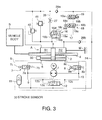
FIG. 3 is a hydraulic circuit diagram of a vehicle body tilting device according to a second embodiment of this invention. -
FIG. 4 is a hydraulic circuit diagram of a vehicle body tilting device according to a third embodiment of this invention. - Referring to
FIG. 1 of the drawings, a vehicle body B of a railway vehicle is supported relative to a bogie W via a pendulum beam D to be capable of rocking in a lateral direction. An actuator A of a vehicle body tilting device is interposed between the pendulum beam D and the bogie W. - The actuator A is constituted by a double rod linear actuator. A
cylinder 2 is joined by a hinge to the bogie W via abracket 2a. One end of apiston rod 4 is joined by a hinge to the pendulum beam D. Another end of thepiston rod 4 is a free end. - Referring to
FIG. 2 , the vehicle body tilting device comprises the actuator A, anactuator circuit 5 that supplies oil pressure to the actuator A, and a damping andlocking circuit 13 that causes the actuator A to function as a damper and an inhibiting cylinder. - The actuator A comprises a
piston 3 accommodated in thecylinder 2 to be free to slide. Thepiston rod 4 is joined to thepiston 3 so as to project from both axial direction sides of thecylinder 2. Two pressure chambers R1 and R2 are defined in thecylinder 2 by thepiston 3. - The
actuator circuit 5 comprises a bidirectional dischargehydraulic pump 1 driven by an electric motor M, two ports that function as a suction port and a discharge port of thehydraulic pump 1 in accordance with a rotation direction of thehydraulic pump 1, anoil passage 9 connected to one port, and anoil passage 10 connected to the other port. Theoil passage 9 is connected to one of the pressure chambers R1 in thecylinder 2 via asolenoid switch valve 7. Theoil passage 10 is connected to the other pressure chamber R2 in thecylinder 2 via asolenoid switch valve 8. - One or both of the
oil passages accumulator 11 via a lowpressure selection valve 12. Theaccumulator 11 also collects leaked oil pressure leaking from thehydraulic pump 1. - The
solenoid switch valve 7 includes a valvemain body 7a having a communicating position in which theoil passage 9 communicates with the pressure chamber R1 and a check position in which working oil is allowed to flow from theoil passage 9 into the pressure chamber R1 but prevented from flowing in reverse. Thesolenoid switch valve 7 includes aspring 7b that biases the valvemain body 7a to the check position, and asolenoid 7c that switches the valvemain body 7a to the communicating position against thespring 7b through magnetic excitation. - The
solenoid switch valve 8 includes a valvemain body 8a having a communicating position in which theoil passage 10 communicates with the pressure chamber R2 and a check position in which working oil is allowed to flow from theoil passage 10 into the pressure chamber R2 but prevented from flowing in reverse. Thesolenoid switch valve 8 includes aspring 8b that biases the valvemain body 8a to the check position, and asolenoid 8c that switches the valvemain body 8a to the communicating position against thespring 8b through magnetic excitation. - The low
pressure selection valve 12 includes a valvemain body 12a having a first position in which theoil passage 9 communicates with theaccumulator 11, a second position in which theoil passage 10 communicates with theaccumulator 11, and a third position in which both theoil passage 9 and theoil passage 10 communicate with theaccumulator 11. The lowpressure selection valve 12 also includes apilot passage 12b that applies the pressure of theoil passage 9 to the valvemain body 12a to bias the valvemain body 12a toward the second position, and apilot passage 12c that applies the pressure of theoil passage 10 to the valvemain body 12a to bias the valvemain body 12a toward the first position. In a neutral state, the lowpressure selection valve 12 is positioned in the third position. - When the pressure on the
oil passage 9 side exceeds the pressure on theoil passage 10 side, the lowpressure selection valve 12 switches to the second position such that theoil passage 10 communicates with theaccumulator 11. When the pressure on theoil passage 10 side exceeds the pressure on theoil passage 9 side, the lowpressure selection valve 12 switches to the first position such that theoil passage 9 communicates with theaccumulator 11. - The damping and
locking circuit 13 includes aflow passage 14b communicating with the pressure chamber R1 of the cylinder C, and aflow passage 14c communicating with the pressure chamber R2 of the cylinder C. Theflow passage 14b is connected to ashutoff valve 16 via acheck valve 20. Theflow passage 14c is connected to theshutoff valve 16 via acheck valve 21. Thecheck valves flow passages shutoff valve 16 and prevent working oil from flowing in reverse. - The
shutoff valve 16 includes avalve body 16a, aspring 16e that biases thevalve body 16a in a closing direction, avalve seat 16b that seats thevalve body 16a, aback pressure chamber 16f that applies back pressure to thevalve body 16a, adrain passage 17 that releases the back pressure, and apassage 16c having anorifice 16d, which leads oil pressure upstream of thevalve seat 16b to theback pressure chamber 16f through thevalve body 16a. - A normally open
solenoid switch valve 18 and asolenoid switch valve 19 are provided in series in thedrain passage 17. Thesolenoid switch valve 18 includes a valvemain body 18a having a communicating position in which thesolenoid switch valve 18 communicates with thedrain passage 17 via an internal orifice, and a check position in which working oil is allowed to flow from thedrain passage 17 into theback pressure chamber 16f but prevented from flowing in reverse. Thesolenoid switch valve 18 also includes aspring 18b that biases the valvemain body 18a toward the communicating position, and asolenoid 18c that switches the valvemain body 18a to the check position against thespring 18b through excitation. - The
solenoid switch valve 19 is a solenoid two position switch valve which includes a valvemain body 19a having a communicating position in which thesolenoid switch valve 19 communicates with thedrain passage 17 via an internal orifice, and a check position in which working oil is allowed to flow from thedrain passage 17 into theback pressure chamber 16f but prevented from flowing in reverse. Thesolenoid switch valve 19 switches these positions in accordance with selective excitation of a plurality ofsolenoids 19b. When none of thesolenoids 19b is excited, thesolenoid switch valve 19 maintains the position obtained through the previous excitation. Instead of thesolenoid switch valve 19, any switch valve that is switched by a manual or other operation and has a function for maintaining its last position until a new switch operation is performed may be used. - Instead of the check position, the
solenoid switch valves solenoid switch valves drain passage 17 via the internal orifice in the communicating position, but the orifice may be omitted such that the working oil in thedrain passage 17 flows freely. The orifice is provided to suppress rapid displacement of thevalve body 16a of theshutoff valve 16, thereby preventing noise when thevalve body 16a is seated on thevalve seat 16b and chattering in thevalve body 16a. - When either one of the
solenoid switch valves back pressure chamber 16f enters an oil lock state, and therefore thevalve body 16a of theshutoff valve 16 cannot be lifted. In this case, both theflow passage 14b and theflow passage 14c are shut off from amain flow passage 14a. - When the
solenoid switch valves valve body 16a is lifted from thevalve seat 16b in accordance with the pressure in theflow passage 14b or theflow passage 14c, and as a result, the working oil in theflow passage 14b or theflow passage 14c flows downstream into themain passage 14a. - The
main flow passage 14a is provided with a dampingvalve 15 that varies a flow passage area in accordance with an upstream side pressure, and anorifice 15b for bypassing the dampingvalve 15. When the upstream pressure is low, the dampingvalve 15 does not open, and therefore the working oil in themain flow passage 14a flows through theorifice 15b. The dampingvalve 15 opens when the upstream pressure of theorifice 15b rises above a predetermined cranking pressure due to an increase in flow rate through themain flow passage 14a. When the actuator A functions as a damper, the dampingvalve 15 and theorifice 15b function as a damping force generating element for generating a damping force by applying resistance to the flow of themain flow passage 14a as thepiston rod 4 elongates and contracts. - The
main flow passage 14a is connected to theaccumulator 11 via a connectingpassage 24 downstream of the dampingvalve 15 and theorifice 15b. The connectingpassage 24 is connected to theflow passage 14b via aflow passage 14d and acheck valve 22 and to theflow passage 14c via aflow passage 14e and acheck valve 23. Thecheck valve 22 functions to allow working oil to flow from the connectingpassage 24 into theflow passage 14b and prevent working oil from flowing out of theflow passage 14b into the connectingpassage 24. Thecheck valve 23 functions to allow working oil to flow from the connectingpassage 24 into theflow passage 14c and prevent working oil from flowing out of theflow passage 14c into the connectingpassage 24. - The damping and locking
circuit 13 further comprises arelief valve 25 that opens when theflow passage 14b or theflow passage 14c reach or exceed a fixed high pressure to allow the excess pressure to escape into theaccumulator 11 through the connectingpassage 24. - Using the
actuator circuit 5 and the damping and lockingcircuit 13 constructed as described above, the vehicle body tilting device functions as follows. - When the
hydraulic pump 1 is driven to rotate in a direction for supplying oil pressure to the pressure chamber R1 while thesolenoid switch valves shutoff valve 16 is closed, thepiston 3 in the cylinder C is propelled in a rightward direction ofFIGs. 1 and2 by the oil pressure supplied to the pressure chamber R1, and as a result, thepiston rod 4 tilts the vehicle body B in a counterclockwise direction ofFIG. 1 . When thehydraulic pump 1 is driven to rotate in a direction for supplying oil pressure to the pressure chamber R2 while thesolenoid switch valves shutoff valve 16 are held in the same state, thepiston 3 in the cylinder C is propelled in a leftward direction ofFIGs. 1 and2 by the oil pressure supplied to the pressure chamber R2, and as a result, thepiston rod 4 tilts the vehicle body B in a clockwise direction ofFIG. 1 . Thus, the vehicle body tilting device functions as an actuator for tilting the vehicle body. - When oil pressure is to be supplied to the pressure chamber R1, the
hydraulic pump 1 suctions working oil from the pressure chamber R2, or from theaccumulator 11 connected to theoil passage 10 via the lowpressure selection valve 12 in the second position, pressurizes the suctioned working oil, and discharges the pressurized working oil into theoil passage 9. When oil pressure is to be supplied to the pressure chamber R2, thehydraulic pump 1 suctions working oil from the pressure chamber R1, or from theaccumulator 11 connected to theoil passage 9 via the lowpressure selection valve 12 in the first position, pressurizes the suctioned working oil, and discharges the pressurized working oil into theoil passage 10. - When necessary, the
accumulator 11 supplies the working oil to be suctioned by thehydraulic pump 1, and therefore, even if a working oil volume in thecylinder 2 decreases due to a temperature decrease or the like, thehydraulic pump 1 can supply oil pressure to the oil chamber R1 or R2 without problems. - The low
pressure selection valve 12 switches from the first position to the second position or from the second position to the first position via the third position whenever the orientation of thrust applied to thepiston 3 by thehydraulic pump 1 reverses. - The low
pressure selection valve 12 is provided to prevent an internal pressure of the cylinder C from rising excessively due to an increase in the temperature of the working oil, to prevent the internal pressure of the cylinder C from turning negative due to a reduction in the temperature of the working oil, to compensate for a volume difference between the pressure chamber R1 and the other chamber R2 due to a manufacturing error in the cylinder C, and so on using the accumulated pressure of theaccumulator 11. - The vehicle body tilting device comprises a
stroke sensor 30 that detects a stroke position of thepiston 3, or in other words displacement of thepiston rod 4. An operation of thehydraulic pump 1 is controlled on the basis of the displacement of thepiston 3 detected by thestroke sensor 30. More specifically, elongation/contraction of the actuator A is feedback-controlled such that a tilt angle of the vehicle body corresponds to a target tilt angle. - Next, a case in which the
solenoid switch valves actuator circuit 5 does not drive the actuator A will be considered. - When the
shutoff valve 16 is closed such that themain flow passage 14a is shut off, communication between the pressure chambers R1 and R2 of the cylinder C is blocked. In this state, the actuator A enters a locked state and functions as an inhibiting cylinder to lock tilting of the vehicle body relative to the bogie. - When the actuator A is forced to elongate and contract by an external force while the
shutoff valve 16 is open such that themain flow passage 14a is connected to the pressure chamber R1 or R2, working oil moves into the pressure chamber R2 from the pressure chamber R1 via theflow passage 14b, themain flow passage 14a, and theflow passage 14e. Alternatively, working oil moves into the pressure chamber R1 from the pressure chamber R2 via theflow passage 14c, themain flow passage 14a, and theflow passage 14d. In both cases, the working oil passes through the dampingvalve 15 or theorifice 15b while generating damping force. In other words, the actuator A elongates and contracts while generating damping force relative to a load of the forcing power of the external force, and therefore the vehicle body tilting device functions as a damper. - When an excessive load is applied to the actuator A in an elongation/ contraction direction regardless of the open/closed state of the
shutoff valve 16 such that the internal pressure of the pressure chamber R1 or the pressure chamber R2 becomes abnormally high, therelief valve 25 opens. Therelief valve 25 diverts the high internal pressure of the pressure chamber R1 or the pressure chamber R2 through theshutoff valve 16 and the dampingvalve 15 or theorifice 15b so that the pressure escapes to the low pressure side pressure chamber R2 or R1. - When the volume of the working oil in the actuator A and the damping and locking
circuit 13 decreases due to temperature variation or the like, theaccumulator 11 provides supplementary working oil to the pressure chamber R1 via thecheck valve 22 or to the pressure chamber R2 via thecheck valve 23. Hence, theactuator circuit 5 and the damping and lockingcircuit 13 include an independent working oil volume compensating circuit. - It should be noted, however, that the
actuator circuit 5 and damping and lockingcircuit 13 do not necessarily have to include an independent working oil volume compensating circuit. For example, thesolenoid switch valves circuit 13. - Next, an operation of the vehicle body tilting device having the above construction will be described.
- When the railway vehicle is inoperative, for example when the railway vehicle has finished operating and lowered its pantograph, and is parked in a vehicle terminal, power supply to the railway vehicle is interrupted. In this case, the vehicle body tilting device must function as an inhibiting cylinder for preventing the vehicle body from tilting to ensure that the vehicle body is not caused to tilt by a crosswind or the like.
- In this case, the
solenoid switch valve 19 is switched to the check position before the power supply is interrupted. The normally opensolenoid switch valve 18 is set in the communicating position when the power supply is interrupted. As a result, back pressure acting on thevalve body 16a of theshutoff valve 16 is locked, and therefore theshutoff valve 16 is held in a closed state. Further, thesolenoid switch valves actuator circuit 5 are held in the check position by thesprings - When the pantograph is raised to start an operation of the railway vehicle, the
solenoid 19b of thesolenoid switch valve 19 is excited such that thesolenoid switch valve 19 switches from the check position to the communicating position. After being switched to the communicating position, thesolenoid switch valve 19 maintains the communicating position even when excitation of the solenoid 19c is halted. - Once an operation of the railway vehicle has started, the
solenoid switch valve 18, thesolenoid switch valves hydraulic pump 1 operate as follows in accordance with traveling conditions. - When a traveling speed is lower than a predetermined speed of, for example, 50km/hr or the traveling speed is equal to or greater than the predetermined speed but the railway vehicle is traveling in a straight line or along a gentle curve, the vehicle body does not need to be tilted.
- In this case, the vehicle body tilting device is used as an inhibiting cylinder. As regards the damping and locking
circuit 13, thesolenoid 18c of thesolenoid switch valve 18 is excited such that thesolenoid switch valve 18 is switched to the check position. As a result, working oil outflow from theback pressure chamber 16f that applies back pressure to thevalve body 16a of theshutoff valve 16 is blocked, and therefore theshutoff valve 16 is held in the closed state. As a regards theactuator circuit 5, thesolenoid switch valves solenoid switch valves springs - When the vehicle traveling speed reaches or exceeds 50km/hr, for example, and the railway vehicle passes a curve having an insufficient cant, the vehicle body must be tilted.
- In the damping and locking
circuit 13 in this case, thesolenoid switch valve 18 is supplied with power to switch thesolenoid switch valve 18 to the check position. As a result of this operation, theshutoff valve 16 is fixed in the closed position such that the flow of working oil between the pressure chambers R1 and R2 of the actuator A via the damping and lockingcircuit 13 is blocked. In theactuator circuit 5, thesolenoid switch valves valves hydraulic pump 1 is operated in accordance with a required vehicle body tilting direction. - As a result of the above operations, the
piston 3 displaces in the axial direction within the actuator A, and the pendulum beam D is tilted relative to the bogie W via thepiston rod 4. In other words, the vehicle body tilting device functions as an actuator that tilts the vehicle body B relative to the bogie W. - Oil pressure for driving the actuator A flows directly between the
actuator circuit 5 and the pressure chambers R1 and R2 of the actuator A, without passing through the damping and lockingcircuit 13. Hence, the damping and lockingcircuit 13 does not interfere with theactuator circuit 5, and during elongation and contraction of the actuator A, energy loss due to the working oil entering the damping and lockingcircuit 13 does not occur. - The vehicle body tilting device requires a damper function for allowing the vehicle body B to tilt but suppressing dramatic tilting of the vehicle body B when power supply to the vehicle body tilting device becomes impossible during railway vehicle travel.
- In the damping and locking
circuit 13 in this case, thesolenoid switch valve 18 is maintained in the communicating position by an elastic force of thespring 18b. Thesolenoid switch valve 19 holds the communicating position switched to at the beginning of the operation of the railway vehicle. Hence, theshutoff valve 16 can be opened in accordance with the upstream pressure. - In the
actuator circuit 5, thesolenoid switch valves solenoid switch valves hydraulic pump 1 is not operated. Therefore, working oil does not flow between theactuator circuit 5 and the actuator A, and theactuator circuit 5 does not interfere with the operation of the damping and lockingcircuit 13. - When the railway vehicle passes a curve having a cant in the above state, centrifugal force acts on the vehicle in an outside direction of the curve. A center of gravity of the vehicle body is positioned lower than a center of curvature of the pendulum beam D, and therefore the centrifugal force acts as a force that causes the vehicle body B to tilt toward the inside of the curve. Hence, when the vehicle body B tilts relative to the bogie W, the
piston 3 slides within thecylinder 2 such that the pressure in the pressure chamber R1 and the pressure in the pressure chamber R2 become unbalanced. As a result of this operation, working oil flows between the pressure chambers R1 and R2 via the damping and lockingcircuit 13. - More specifically, when the vehicle body B is tilted in the counterclockwise direction of
FIG. 1 by the centrifugal force, thepiston 3 displaces to the pressure chamber R2 side such that a part of the working oil in the pressure chamber R2 flows into the pressure chamber R1 via theflow passage 14c, thecheck valve 21, theshutoff valve 16, themain flow passage 14a, theorifice 15b, thecheck valve 22, and theflow passage 14b. During this process, theorifice 15b generates a damping force based on the flow resistance, and therefore the vehicle body tilting device functions as a damper that damps the tilting of the vehicle body generated by the centrifugal force. When the flow rate through theorifice 15b reaches or exceeds a fixed level, the flow resistance of theorifice 15b reaches a maximum. In this case, the dampingvalve 15 opens, whereby working oil is caused to flow into the pressure chamber R1 from themain flow passage 14a via theflow passage 14d and theflow passage 14b by a damping force based on the flow resistance of the dampingvalve 15. - When the vehicle body B is tilted in the clockwise direction of
FIG. 1 by the centrifugal force, thepiston 3 displaces to the pressure chamber R1 side such that a part of the working oil in the pressure chamber R1 flows into the pressure chamber R2 via theflow passage 14b, thecheck valve 20, theshutoff valve 16, themain flow passage 14a, theorifice 15b, thecheck valve 23, and theflow passage 14c. During this process, theorifice 15b generates a damping force based on the flow resistance, and therefore the vehicle body tilting device functions as a damper that damps the tilting of the vehicle body generated by the centrifugal force. When the flow rate through theorifice 15b reaches or exceeds a fixed level, the flow resistance of theorifice 15b reaches a maximum. In this case, the dampingvalve 15 opens, whereby working oil is caused to flow into the pressure chamber R2 from themain flow passage 14a via theflow passage 14e and theflow passage 14c while generating a damping force based on the flow resistance of the dampingvalve 15. - Hence, when the vehicle body tilting device fails during travel, the vehicle body tilting device functions as a damper that allows the vehicle body B to tilt in the center of curvature direction of the curve but prevents the vehicle body B from tilting rapidly.
- In other words, when power is not supplied, the vehicle body tilting device functions as an inhibiting cylinder in a case where the railway vehicle is inoperative, and functions as a damper in a case where the vehicle body tilting device fails. Hence, the single actuator A can be used as an actuator, a damper, and an inhibiting cylinder, depending on conditions.
- Therefore, the vehicle body tilting device can be reduced in size, and as a result, the entire hydraulic vehicle body tilting device, including the
hydraulic pump 1, the electric motor, and the actuator A, can be housed in the narrow space between the vehicle body B and the bogie W. Moreover, the single actuator A can be used as an actuator, a damper, and an inhibiting cylinder, depending on conditions, and therefore the manufacturing cost of the vehicle body tilting device can be reduced. - When applied to a railway vehicle that travels on snow-covered ground, this small vehicle body tilting device can be accommodated within the pendulum beam. Therefore, operational defects in the vehicle body tilting device caused by snow and ice sticking to the device can be avoided.
- Moreover, since the vehicle body tilting device uses oil pressure, greater thrust and improved responsiveness can be obtained in comparison with a conventional vehicle body tilting device that uses air pressure. As a result, passenger comfort in the railway vehicle can be improved.
- Referring to
FIG. 3 , a second embodiment of this invention will be described. - This embodiment differs from the first embodiment in the constitution of the damping and locking
circuit 13. In this embodiment, damping force is generated by anorifice 27 alone instead of the dampingvalve 15 and theorifice 15b. Theorifice 27 is provided in aflow passage 26 in series with theshutoff valve 16. One end of theflow passage 26 is connected to the pressure chamber R1, and the other end of theflow passage 26 is connected to the pressure chamber R2. - The connecting
passage 24 extending from theaccumulator 11 is connected to the pressure chamber R1 via acheck valve 29a. The connectingpassage 24 extending from theaccumulator 11 is connected to the pressure chamber R2 via acheck valve 29b. -
Parallel relief valves flow passage 26. When the pressure of the pressure chamber R1 becomes abnormally high, therelief valve 41 allows working oil to escape from the pressure chamber R1 into the pressure chamber R2 through theflow passage 26. When the pressure of the pressure chamber R2 becomes abnormally high, therelief valve 42 allows working oil to escape from the pressure chamber R2 into the pressure chamber R1 through theflow passage 26. - According to this embodiment, similar effects to the first embodiment are obtained, and in addition, the constitution of the damping and locking
circuit 13 can be simplified. - Referring to
FIG. 4 , a third embodiment of this invention will be described. - This embodiment differs from the first embodiment in the constitution of the damping and locking
circuit 13. Furthermore, an axial piston pump is used as thehydraulic pump 1. All other constitutions of theactuator circuit 5 are identical to those of the first embodiment. - With regard to the damping and locking
circuit 13, in this embodiment, a normally opensolenoid switch valve 43 is used in place of theshutoff valve 16 and thesolenoid switch valves circuit 13 are identical to those of the first embodiment. - The
solenoid switch valve 43 includes a valvemain body 43a having a communicating position in which working oil is permitted to flow in both directions of themain flow passage 14a, and a check position in which working oil is prevented from flowing from themain flow passage 14a in the direction of theorifice 15b but allowed to flow in reverse. Thesolenoid switch valve 43 also includes aspring 43b that biases the valvemain body 43a toward the communicating position, and asolenoid 43c that switches the valvemain body 43a to the check position against thespring 43b through excitation. - When not excited, the
solenoid switch valve 43 is held in the communicating position by an elastic force of thespring 43b. In this state, the actuator A elongates and contracts under the damping force generated by theorifice 15b and dampingvalve 15, whereby the vehicle body tilting device functions as a damper. - When the railway vehicle does not require vehicle body tilting, i.e. when the traveling speed is lower than the predetermined speed or when the traveling speed is equal to or higher than the predetermined speed but the railway vehicle is traveling in a straight line or along a gentle curve, the
solenoid switch valve 43 is switched to the check position by exciting thesolenoid 43c. As a result, working oil is prevented from flowing out of the oil chambers R1 and R2 of the actuator A by thesolenoid switch valve 43. In theactuator circuit 5, thehydraulic pump 1 is not driven, and therefore thesolenoid switch valves - On the other hand, when the railway vehicle requires vehicle body tilting, i.e. when the vehicle traveling speed is equal to or greater than the predetermined speed and the railway vehicle passes a curve having an insufficient cant, the
solenoid switch valve 43 is held in the check position and thesolenoids solenoid switch valves actuator circuit 5 are excited to switch thesolenoid switch valves hydraulic pump 1. In the damping and lockingcircuit 13, thesolenoid switch valve 43 is in the check position, and therefore working oil is prevented from flowing out of the pressure chambers R1 and R2 of the actuator A via the damping and lockingcircuit 13. Hence, the actuator A is driven to elongate and contract by the oil discharged from thehydraulic pump 1, and the vehicle body tilting device functions as an actuator for tilting the vehicle body B relative to the bogie W. - When power supply to the vehicle body tilting device becomes impossible while the railway vehicle is traveling, the
solenoid switch valve 43 of the damping and lockingcircuit 13 is held in the communicating position by the elastic force of thespring 43b. Meanwhile, thesolenoid switch valves actuator circuit 5 are held in the check position by the elastic force of thesprings orifice 15b and the dampingvalve 15, and thus the vehicle body tilting device functions as a damper. The vehicle body tilting device functions similarly as a damper both when the railway vehicle is inoperative and when the vehicle body tilting device fails. - The difference between this embodiment and the first and second embodiments is in the response exhibited when the railway vehicle is inoperative. In the first and second embodiments, the vehicle body tilting device functions as an inhibiting cylinder when the railway vehicle is inoperative and as a damper when the vehicle body tilting device fails. In this embodiment, however, the vehicle body tilting device functions as a damper in both cases. Hence, according to this invention, the function of the vehicle body tilting device when the railway vehicle is inoperative can be set as desired by varying the constitution of the damping and locking
circuit 13. - Meanwhile, by using an axial piston pump as the
hydraulic pump 1, the following effects are obtained. - An axial piston pump is a well-known pump having the following specific constitution. An axial piston pump includes a cylinder block that is housed in a housing to be free to rotate and is driven to rotate by an electric motor M, an odd number of cylinder holes formed in the cylinder block at equal intervals on an identical circumference, a piston inserted into each cylinder hole to be free to slide, a piston shoe that supports one end of each piston via a ball joint, a swash plate that slides along the piston shoe so as to tilt the piston shoe relative to an axis of the cylinder block, and a valve plate that contacts an end surface of the cylinder block so as to be free to slide and forms an intake port and a discharge port. The axial piston pump is capable of bidirectional discharge in accordance with a rotation direction of the electric motor M. Further, a discharge flow rate is varied in accordance with a rotation speed of the electric motor M. The swash plate may be a fixed angle type or a variable angle type.
- In accordance with rotation of the axial piston pump, the piston shoe is pushed toward the swash plate by pressure generated in the cylinder and the cylinder block is urged toward the valve plate. As a result, a frictional force against the rotation of the cylinder block is generated between the piston shoe and the swash plate and between the cylinder block and the valve plate. In contrast to a pressure loading gear pump or a pressure balance gear pump, the frictional force does not increase, and when the axial piston pump is driven to rotate, the torque required thereby is not as large as that of a pressure loading gear pump or a pressure balance gear pump. A feature of an axial piston pump is that it can be driven to rotate by a smaller external input than a gear pump.
- The axial piston pump constituting the
hydraulic pump 1 generates a smaller frictional resistance force relative to rotational driving than a gear pump, and can be rotated by a smaller torque. Therefore, when torque equal to or greater than an output of the electric motor M is input externally, the actuator A can be caused to elongate and contract more easily, whereby the apparent rigidity of the actuator A decreases in comparison with a conventional actuator. - When the vehicle body tilting device is used as an actuator, the
solenoid switch valve 43 is held in the check position by electrifying thesolenoid 43c. Therefore, working fluid does not pass through the damping and lockingcircuit 13, and the damper function generated by the damping and lockingcircuit 13 is not activated. According to this embodiment, however, when torque equal to or greater than the output of the electric motor M is input externally, the actuator A elongates and contracts under a damping force based on the frictional resistance force of thehydraulic pump 1. Therefore, the vehicle body tilting device can function as a damper while also functioning as an actuator. Hence, according to this embodiment, vibration and impacts input into the actuator A externally can be absorbed while the vehicle body B is tilted relative to the bogie W. According to this embodiment, sufficient thrust and responsiveness can be generated by the hydraulic vehicle body tilting device, and vibration and impacts can be absorbed while the vehicle body B is tilted. Therefore, a favorable effect in terms of improving the passenger comfort of the railway vehicle is obtained. - The contents of
Tokugan 2007-315569 Tokugan 2007-315570, with a filing date of December 6, 2007 - Although the invention has been described above with reference to certain embodiments, the invention is not limited to the embodiments described above. Modifications and variations of the embodiments described above will occur to those skilled in the art, within the scope of the claims.
- For example, in each of the above embodiments, this invention is applied to a railway vehicle having a vehicle body that is tilted using a so-called pendulum structure, but this invention may also be applied to a railway vehicle in which left and right actuators are interposed between the vehicle body B and the bogie W in a vertical orientation and the vehicle body B is tilted by causing these actuators to elongate and contract.
- Further, the driving medium of the actuator A is not limited to working oil, and any other incompressible fluid may be used.
- As described above, with the vehicle body tilting device according to this invention, a vehicle can be tilted with sufficient thrust and responsiveness using a single hydraulic actuator, and the actuator can be caused to function as a damper relative to the action of an external force. Therefore, the hydraulic vehicle body tilting device can be reduced in size, and as a result of this size reduction, the vehicle body tilting device can be housed in a pendulum beam between a vehicle body and a bogie of a railway vehicle. Hence, by applying the vehicle body tilting device according to this invention to a railway vehicle used in a cold region, operational defects in the vehicle body tilting device caused by snow and ice sticking thereto can be prevented.
- The embodiments of this invention in which an exclusive property or privilege is claimed are defined as follows:
Claims (11)
- A vehicle body tilting device for a railway vehicle, characterized by:a telescopic hydraulic actuator (A) interposed between a vehicle body (D) and a bogie (W) of the railway vehicle;an actuator circuit (5) that drives the hydraulic actuator (A) to elongate and contract; anda damping and locking circuit (13) that damps elongation/contraction of the hydraulic actuator (A) caused by an external force and includes a shutoff mechanism (17, 18, 19, 43) that shuts off a flow of working fluid accompanying the elongation/contraction of the hydraulic actuator (A) caused by the external force.
- The vehicle body tilting device for a railway vehicle as defined in Claim 1, characterized in that the hydraulic actuator (A) comprises a cylinder (2), a piston (3) housed in the cylinder (2) to be free to slide, a piston rod (4) that is joined to the piston (3) and projects outward from the cylinder (2), and two pressure chambers (R1, R2) defined in the cylinder (2) by the piston (3).
- The vehicle body tilting device for a railway vehicle as defined in Claim 2, characterized in that the damping and locking circuit (13) comprises a flow passage (14a, 14b, 14c, 14d, 14e, 26) that connects the two pressure chambers (R1, R2), a shutoff valve (16, 43) that shuts off a predetermined direction flow of the flow passage (14a, 14b, 14c, 14d, 14e, 26) when operated, and a damping force generating element (15, 15b, 27) that applies a resistance to fluid flowing through the shutoff valve (16, 43) in an open state.
- The vehicle body tilting device for a railway vehicle as defined in Claim 3, characterized in that
the shutoff valve (16, 43) comprises a valve seat (16b), a valve body (16a) that sits on the valve seat (16b), a spring (16e) that biases the valve body (16a) toward the valve seat (16b), and a back pressure chamber (16f) that applies a back pressure to the valve body (16a),
the valve body (16a) is configure to shut off the flow of working fluid through the flow passage (14a, 14b, 14c, 14d, 14e, 26) when seated on the valve seat (16b) and separate from the valve seat (16b), when the back pressure in the back pressure chamber (16f) is released, in accordance with a pressure in a high pressure side pressure chamber of the two pressure chambers (R1, R2) to allow working fluid to flow through the flow passage (14a, 14b, 14c, 14d, 14e, 26), and
the shutoff mechanism (17, 18, 19, 43) comprises a drain passage (17) that releases the back pressure in the back pressure chamber (16f), and a solenoid switch valve (18, 19) that shuts off the drain passage (17). - The vehicle body tilting device for a railway vehicle as defined in Claim 4, characterized in that the solenoid switch valve (18, 19) is constituted by a normally open solenoid switch valve (18) that sets the drain passage (17) in a shutoff state when excited, and a self-holding solenoid two-position switch valve (19) that is disposed in series with the normally open solenoid switch valve (18) and sets the drain passage (17) in the shutoff state or a communicating state when excited.
- The vehicle body tilting device for a railway vehicle as defined in Claim 3, characterized in that the shutoff valve (16, 43) is constituted by a solenoid switch valve (43) that shuts off a predetermined direction flow of working fluid through a flow passage (26) when excited.
- The vehicle body tilting device for a railway vehicle as defined in any one of Claim 3 through Claim 6, characterized in that the damping force generating element (15, 15b, 27) comprises an orifice (15b) and a damping valve (15) disposed parallel to the orifice (15b).
- The vehicle body tilting device for a railway vehicle as defined in any one of Claim 3 through Claim 6, characterized in that the damping force generating element (15, 15b, 27) is constituted by an orifice (27) provided in the flow passage (26) connecting the two pressure chambers (R1, R2).
- The vehicle body tilting device for a railway vehicle as defined in any one of Claim 2 through Claim 8, characterized by an accumulator (11) that stores fluid which flows out of either of the two pressure chambers (R1, R2) via the damping and locking circuit (13) and supplies fluid to the pressure chamber (R1, R2) that has decreased in pressure via the damping and locking circuit (13).
- The vehicle body tilting device for a railway vehicle as defined in Claim 2, characterized in that the actuator circuit (5) comprises two passages (9, 10) connected respectively to the two pressure chambers (R1, R2), a bidirectional discharge hydraulic pump (1) that suctions working fluid from one of the two passages (9, 10) and discharges the suctioned working fluid to the other of the two passages (9, 10), and a solenoid switch valve (7, 8) provided in each of the two passages (9, 10), which prevents working fluid from flowing out of the two pressure chambers (R1, R2) when excited.
- The vehicle body tilting device for a railway vehicle as defined in Claim 10, characterized in that the hydraulic pump (1) is constituted by an axial piston pump.
Applications Claiming Priority (3)
| Application Number | Priority Date | Filing Date | Title |
|---|---|---|---|
| JP2007315569A JP4997084B2 (en) | 2007-12-06 | 2007-12-06 | Actuator |
| JP2007315570A JP5190871B2 (en) | 2007-12-06 | 2007-12-06 | Actuator |
| PCT/JP2008/072588 WO2009072672A1 (en) | 2007-12-06 | 2008-12-05 | Vehicle body tilting device for railroad vehicle |
Publications (3)
| Publication Number | Publication Date |
|---|---|
| EP2216228A1 true EP2216228A1 (en) | 2010-08-11 |
| EP2216228A4 EP2216228A4 (en) | 2016-03-09 |
| EP2216228B1 EP2216228B1 (en) | 2017-05-03 |
Family
ID=40717843
Family Applications (1)
| Application Number | Title | Priority Date | Filing Date |
|---|---|---|---|
| EP08857057.7A Not-in-force EP2216228B1 (en) | 2007-12-06 | 2008-12-05 | Vehicle body tilting device for railroad vehicle |
Country Status (6)
| Country | Link |
|---|---|
| EP (1) | EP2216228B1 (en) |
| KR (1) | KR101138167B1 (en) |
| CN (1) | CN101674967B (en) |
| AU (1) | AU2008332258B2 (en) |
| ES (1) | ES2627440T3 (en) |
| WO (1) | WO2009072672A1 (en) |
Cited By (4)
| Publication number | Priority date | Publication date | Assignee | Title |
|---|---|---|---|---|
| EP2703248A3 (en) * | 2012-08-31 | 2014-04-16 | VR-Yhtymä Oy | Tilt control |
| EP2722248A4 (en) * | 2011-06-20 | 2015-04-01 | Kayaba Industry Co Ltd | DAMPER DEVICE FOR A RAIL VEHICLE |
| EP3708454A1 (en) * | 2019-03-11 | 2020-09-16 | ALSTOM Transport Technologies | Railway vehicle comprising a system for semi-active damping and associated circulation method |
| EP4385850A1 (en) * | 2022-12-15 | 2024-06-19 | Liebherr-Transportation Systems GmbH & Co. KG | Actuator for a tilting system of a rail vehicle |
Families Citing this family (7)
| Publication number | Priority date | Publication date | Assignee | Title |
|---|---|---|---|---|
| CN103711830A (en) * | 2013-12-24 | 2014-04-09 | 常州容大结构减振设备有限公司 | Novel intelligent damper |
| KR101722493B1 (en) | 2016-07-14 | 2017-04-06 | 한국철도기술연구원 | Damper for generating variable damping force using variable resistor, and vibration system having the same |
| CN108528607A (en) * | 2018-06-11 | 2018-09-14 | 重庆中铃兆虎机车制造有限公司 | Damper of tricycle |
| PL235880B1 (en) * | 2018-10-30 | 2020-11-02 | Hyper Poland Spolka Z Ograniczona Odpowiedzialnoscia | System for semi-active compensation of lateral overloads in motor vehicles |
| CN109823364B (en) * | 2019-03-01 | 2021-01-26 | 中铁二院工程集团有限责任公司 | Control system for improving riding comfort of suspended monorail train and implementation method |
| CN110360260B (en) * | 2019-06-20 | 2021-08-31 | 中车青岛四方机车车辆股份有限公司 | An active control anti-serpentine shock absorber and vibration reduction system, vehicle |
| DE102023116042A1 (en) * | 2023-06-20 | 2024-12-24 | Liebherr-Transportation Systems Gmbh & Co Kg | electrohydraulic actuator |
Family Cites Families (7)
| Publication number | Priority date | Publication date | Assignee | Title |
|---|---|---|---|---|
| DE19512437A1 (en) * | 1995-04-03 | 1996-10-10 | Rexroth Mannesmann Gmbh | Device for compensating the lateral force acting on a rail vehicle |
| DE19703322C1 (en) * | 1997-01-30 | 1998-03-26 | Abb Daimler Benz Transp | Carriage body inclination control module for rail vehicle |
| JP2002114144A (en) * | 2000-10-06 | 2002-04-16 | Nippon Sharyo Seizo Kaisha Ltd | Damper for vibration suppression |
| JP2003137091A (en) * | 2001-11-05 | 2003-05-14 | Hitachi Ltd | Railcar body tilting device |
| DE10157368A1 (en) * | 2001-11-23 | 2003-06-12 | Bombardier Transp Gmbh | Position adjustment of a vehicle body |
| JP2004291897A (en) * | 2003-03-28 | 2004-10-21 | Railway Technical Res Inst | Body tilt device and railway vehicle |
| JP5160127B2 (en) * | 2007-03-30 | 2013-03-13 | 公益財団法人鉄道総合技術研究所 | Railway vehicle body tilt actuator |
-
2008
- 2008-12-05 WO PCT/JP2008/072588 patent/WO2009072672A1/en not_active Ceased
- 2008-12-05 EP EP08857057.7A patent/EP2216228B1/en not_active Not-in-force
- 2008-12-05 AU AU2008332258A patent/AU2008332258B2/en not_active Ceased
- 2008-12-05 CN CN2008800143169A patent/CN101674967B/en not_active Expired - Fee Related
- 2008-12-05 KR KR1020097023505A patent/KR101138167B1/en not_active Expired - Fee Related
- 2008-12-05 ES ES08857057.7T patent/ES2627440T3/en active Active
Non-Patent Citations (1)
| Title |
|---|
| See references of WO2009072672A1 * |
Cited By (7)
| Publication number | Priority date | Publication date | Assignee | Title |
|---|---|---|---|---|
| EP2722248A4 (en) * | 2011-06-20 | 2015-04-01 | Kayaba Industry Co Ltd | DAMPER DEVICE FOR A RAIL VEHICLE |
| US9233695B2 (en) | 2011-06-20 | 2016-01-12 | Kayaba Industry Co., Ltd. | Railcar damping device |
| EP2703248A3 (en) * | 2012-08-31 | 2014-04-16 | VR-Yhtymä Oy | Tilt control |
| EP3708454A1 (en) * | 2019-03-11 | 2020-09-16 | ALSTOM Transport Technologies | Railway vehicle comprising a system for semi-active damping and associated circulation method |
| FR3093693A1 (en) * | 2019-03-11 | 2020-09-18 | Alstom Transport Technologies | Rail vehicle comprising a semi-active damping system and associated circulation method |
| CN111688748A (en) * | 2019-03-11 | 2020-09-22 | 阿尔斯通运输科技公司 | Railway vehicle comprising a semi-active damping system and relative cycling method |
| EP4385850A1 (en) * | 2022-12-15 | 2024-06-19 | Liebherr-Transportation Systems GmbH & Co. KG | Actuator for a tilting system of a rail vehicle |
Also Published As
| Publication number | Publication date |
|---|---|
| ES2627440T3 (en) | 2017-07-28 |
| EP2216228B1 (en) | 2017-05-03 |
| KR20090130120A (en) | 2009-12-17 |
| EP2216228A4 (en) | 2016-03-09 |
| CN101674967A (en) | 2010-03-17 |
| AU2008332258B2 (en) | 2011-09-15 |
| WO2009072672A1 (en) | 2009-06-11 |
| AU2008332258A1 (en) | 2009-06-11 |
| KR101138167B1 (en) | 2012-04-23 |
| CN101674967B (en) | 2011-10-26 |
Similar Documents
| Publication | Publication Date | Title |
|---|---|---|
| EP2216228B1 (en) | Vehicle body tilting device for railroad vehicle | |
| TWI475161B (en) | Hydraulic cylinder device | |
| JP5389461B2 (en) | Hydraulic motor | |
| US9422052B2 (en) | Electro hydrostatic actuator system for retracting/extending landing gear | |
| US20170267050A1 (en) | Motor vehicle chassis | |
| US20150184683A1 (en) | Actuator | |
| KR101718640B1 (en) | Actuator unit | |
| JP2000145955A (en) | Neutral return buffer mechanism of axle driving device | |
| US12344065B2 (en) | Single axle roll control system with multiple pressurizing devices arranged in series | |
| WO2011048958A1 (en) | Hydraulic motor-driving device | |
| US12497957B2 (en) | Pre-pressurized system with reverse rotation of pump for valve actuation | |
| JP5190871B2 (en) | Actuator | |
| JP2011025751A (en) | Actuator | |
| JP2024516456A (en) | Automobile suspension device | |
| JP7801146B2 (en) | Cylinder Device | |
| JP6977072B2 (en) | Switching valve, electro-hydraulic circuit and aircraft | |
| JP7446852B2 (en) | Railroad vehicle vibration damping device | |
| JP3907292B2 (en) | Pilot pressure controller for hydraulic servo mechanism | |
| JP2011106606A (en) | Hydraulic motor driving device | |
| JP2007276525A (en) | Hydraulic pressure source device | |
| US20260077627A1 (en) | Active Suspension System | |
| JPH03109119A (en) | suspension control device | |
| JP6675924B2 (en) | Suspension device | |
| CN119428051A (en) | A dual-valve controlled fully active automobile suspension system |
Legal Events
| Date | Code | Title | Description |
|---|---|---|---|
| PUAI | Public reference made under article 153(3) epc to a published international application that has entered the european phase |
Free format text: ORIGINAL CODE: 0009012 |
|
| 17P | Request for examination filed |
Effective date: 20091029 |
|
| AK | Designated contracting states |
Kind code of ref document: A1 Designated state(s): AT BE BG CH CY CZ DE DK EE ES FI FR GB GR HR HU IE IS IT LI LT LU LV MC MT NL NO PL PT RO SE SI SK TR |
|
| AX | Request for extension of the european patent |
Extension state: AL BA MK RS |
|
| DAX | Request for extension of the european patent (deleted) | ||
| RAP1 | Party data changed (applicant data changed or rights of an application transferred) |
Owner name: KYB CORPORATION Owner name: RAILWAY TECHNICAL RESEARCH INSTITUTE |
|
| RA4 | Supplementary search report drawn up and despatched (corrected) |
Effective date: 20160204 |
|
| RIC1 | Information provided on ipc code assigned before grant |
Ipc: B61F 5/22 20060101AFI20160129BHEP Ipc: F16F 9/49 20060101ALI20160129BHEP Ipc: F16F 9/20 20060101ALI20160129BHEP |
|
| GRAP | Despatch of communication of intention to grant a patent |
Free format text: ORIGINAL CODE: EPIDOSNIGR1 |
|
| STAA | Information on the status of an ep patent application or granted ep patent |
Free format text: STATUS: GRANT OF PATENT IS INTENDED |
|
| INTG | Intention to grant announced |
Effective date: 20170124 |
|
| GRAS | Grant fee paid |
Free format text: ORIGINAL CODE: EPIDOSNIGR3 |
|
| GRAA | (expected) grant |
Free format text: ORIGINAL CODE: 0009210 |
|
| STAA | Information on the status of an ep patent application or granted ep patent |
Free format text: STATUS: THE PATENT HAS BEEN GRANTED |
|
| RIN1 | Information on inventor provided before grant (corrected) |
Inventor name: KAMOSHITA, SHOGO Inventor name: ITO, TATSUO Inventor name: UCHIDA, MASARU Inventor name: KAZATO, AKIHITO |
|
| RAP1 | Party data changed (applicant data changed or rights of an application transferred) |
Owner name: KYB CORPORATION Owner name: RAILWAY TECHNICAL RESEARCH INSTITUTE |
|
| AK | Designated contracting states |
Kind code of ref document: B1 Designated state(s): AT BE BG CH CY CZ DE DK EE ES FI FR GB GR HR HU IE IS IT LI LT LU LV MC MT NL NO PL PT RO SE SI SK TR |
|
| REG | Reference to a national code |
Ref country code: GB Ref legal event code: FG4D |
|
| REG | Reference to a national code |
Ref country code: AT Ref legal event code: REF Ref document number: 889620 Country of ref document: AT Kind code of ref document: T Effective date: 20170515 Ref country code: CH Ref legal event code: EP |
|
| REG | Reference to a national code |
Ref country code: IE Ref legal event code: FG4D |
|
| REG | Reference to a national code |
Ref country code: DE Ref legal event code: R096 Ref document number: 602008050130 Country of ref document: DE |
|
| REG | Reference to a national code |
Ref country code: ES Ref legal event code: FG2A Ref document number: 2627440 Country of ref document: ES Kind code of ref document: T3 Effective date: 20170728 |
|
| REG | Reference to a national code |
Ref country code: NL Ref legal event code: MP Effective date: 20170503 |
|
| REG | Reference to a national code |
Ref country code: AT Ref legal event code: MK05 Ref document number: 889620 Country of ref document: AT Kind code of ref document: T Effective date: 20170503 |
|
| REG | Reference to a national code |
Ref country code: LT Ref legal event code: MG4D |
|
| PG25 | Lapsed in a contracting state [announced via postgrant information from national office to epo] |
Ref country code: FI Free format text: LAPSE BECAUSE OF FAILURE TO SUBMIT A TRANSLATION OF THE DESCRIPTION OR TO PAY THE FEE WITHIN THE PRESCRIBED TIME-LIMIT Effective date: 20170503 Ref country code: NO Free format text: LAPSE BECAUSE OF FAILURE TO SUBMIT A TRANSLATION OF THE DESCRIPTION OR TO PAY THE FEE WITHIN THE PRESCRIBED TIME-LIMIT Effective date: 20170803 Ref country code: HR Free format text: LAPSE BECAUSE OF FAILURE TO SUBMIT A TRANSLATION OF THE DESCRIPTION OR TO PAY THE FEE WITHIN THE PRESCRIBED TIME-LIMIT Effective date: 20170503 Ref country code: LT Free format text: LAPSE BECAUSE OF FAILURE TO SUBMIT A TRANSLATION OF THE DESCRIPTION OR TO PAY THE FEE WITHIN THE PRESCRIBED TIME-LIMIT Effective date: 20170503 Ref country code: GR Free format text: LAPSE BECAUSE OF FAILURE TO SUBMIT A TRANSLATION OF THE DESCRIPTION OR TO PAY THE FEE WITHIN THE PRESCRIBED TIME-LIMIT Effective date: 20170804 Ref country code: AT Free format text: LAPSE BECAUSE OF FAILURE TO SUBMIT A TRANSLATION OF THE DESCRIPTION OR TO PAY THE FEE WITHIN THE PRESCRIBED TIME-LIMIT Effective date: 20170503 |
|
| PG25 | Lapsed in a contracting state [announced via postgrant information from national office to epo] |
Ref country code: LV Free format text: LAPSE BECAUSE OF FAILURE TO SUBMIT A TRANSLATION OF THE DESCRIPTION OR TO PAY THE FEE WITHIN THE PRESCRIBED TIME-LIMIT Effective date: 20170503 Ref country code: BG Free format text: LAPSE BECAUSE OF FAILURE TO SUBMIT A TRANSLATION OF THE DESCRIPTION OR TO PAY THE FEE WITHIN THE PRESCRIBED TIME-LIMIT Effective date: 20170803 Ref country code: IS Free format text: LAPSE BECAUSE OF FAILURE TO SUBMIT A TRANSLATION OF THE DESCRIPTION OR TO PAY THE FEE WITHIN THE PRESCRIBED TIME-LIMIT Effective date: 20170903 Ref country code: SE Free format text: LAPSE BECAUSE OF FAILURE TO SUBMIT A TRANSLATION OF THE DESCRIPTION OR TO PAY THE FEE WITHIN THE PRESCRIBED TIME-LIMIT Effective date: 20170503 Ref country code: NL Free format text: LAPSE BECAUSE OF FAILURE TO SUBMIT A TRANSLATION OF THE DESCRIPTION OR TO PAY THE FEE WITHIN THE PRESCRIBED TIME-LIMIT Effective date: 20170503 Ref country code: PL Free format text: LAPSE BECAUSE OF FAILURE TO SUBMIT A TRANSLATION OF THE DESCRIPTION OR TO PAY THE FEE WITHIN THE PRESCRIBED TIME-LIMIT Effective date: 20170503 |
|
| PG25 | Lapsed in a contracting state [announced via postgrant information from national office to epo] |
Ref country code: RO Free format text: LAPSE BECAUSE OF FAILURE TO SUBMIT A TRANSLATION OF THE DESCRIPTION OR TO PAY THE FEE WITHIN THE PRESCRIBED TIME-LIMIT Effective date: 20170503 Ref country code: DK Free format text: LAPSE BECAUSE OF FAILURE TO SUBMIT A TRANSLATION OF THE DESCRIPTION OR TO PAY THE FEE WITHIN THE PRESCRIBED TIME-LIMIT Effective date: 20170503 Ref country code: EE Free format text: LAPSE BECAUSE OF FAILURE TO SUBMIT A TRANSLATION OF THE DESCRIPTION OR TO PAY THE FEE WITHIN THE PRESCRIBED TIME-LIMIT Effective date: 20170503 Ref country code: CZ Free format text: LAPSE BECAUSE OF FAILURE TO SUBMIT A TRANSLATION OF THE DESCRIPTION OR TO PAY THE FEE WITHIN THE PRESCRIBED TIME-LIMIT Effective date: 20170503 Ref country code: SK Free format text: LAPSE BECAUSE OF FAILURE TO SUBMIT A TRANSLATION OF THE DESCRIPTION OR TO PAY THE FEE WITHIN THE PRESCRIBED TIME-LIMIT Effective date: 20170503 |
|
| REG | Reference to a national code |
Ref country code: DE Ref legal event code: R097 Ref document number: 602008050130 Country of ref document: DE |
|
| PG25 | Lapsed in a contracting state [announced via postgrant information from national office to epo] |
Ref country code: IT Free format text: LAPSE BECAUSE OF FAILURE TO SUBMIT A TRANSLATION OF THE DESCRIPTION OR TO PAY THE FEE WITHIN THE PRESCRIBED TIME-LIMIT Effective date: 20170503 |
|
| PGFP | Annual fee paid to national office [announced via postgrant information from national office to epo] |
Ref country code: GB Payment date: 20171221 Year of fee payment: 10 |
|
| PLBE | No opposition filed within time limit |
Free format text: ORIGINAL CODE: 0009261 |
|
| STAA | Information on the status of an ep patent application or granted ep patent |
Free format text: STATUS: NO OPPOSITION FILED WITHIN TIME LIMIT |
|
| 26N | No opposition filed |
Effective date: 20180206 |
|
| PGFP | Annual fee paid to national office [announced via postgrant information from national office to epo] |
Ref country code: ES Payment date: 20180117 Year of fee payment: 10 Ref country code: DE Payment date: 20171220 Year of fee payment: 10 |
|
| PG25 | Lapsed in a contracting state [announced via postgrant information from national office to epo] |
Ref country code: SI Free format text: LAPSE BECAUSE OF FAILURE TO SUBMIT A TRANSLATION OF THE DESCRIPTION OR TO PAY THE FEE WITHIN THE PRESCRIBED TIME-LIMIT Effective date: 20170503 |
|
| REG | Reference to a national code |
Ref country code: CH Ref legal event code: PL |
|
| REG | Reference to a national code |
Ref country code: IE Ref legal event code: MM4A |
|
| PG25 | Lapsed in a contracting state [announced via postgrant information from national office to epo] |
Ref country code: LU Free format text: LAPSE BECAUSE OF NON-PAYMENT OF DUE FEES Effective date: 20171205 Ref country code: MT Free format text: LAPSE BECAUSE OF NON-PAYMENT OF DUE FEES Effective date: 20171205 |
|
| REG | Reference to a national code |
Ref country code: FR Ref legal event code: ST Effective date: 20180831 |
|
| REG | Reference to a national code |
Ref country code: BE Ref legal event code: MM Effective date: 20171231 |
|
| PG25 | Lapsed in a contracting state [announced via postgrant information from national office to epo] |
Ref country code: FR Free format text: LAPSE BECAUSE OF NON-PAYMENT OF DUE FEES Effective date: 20180102 Ref country code: IE Free format text: LAPSE BECAUSE OF NON-PAYMENT OF DUE FEES Effective date: 20171205 |
|
| PG25 | Lapsed in a contracting state [announced via postgrant information from national office to epo] |
Ref country code: LI Free format text: LAPSE BECAUSE OF NON-PAYMENT OF DUE FEES Effective date: 20171231 Ref country code: BE Free format text: LAPSE BECAUSE OF NON-PAYMENT OF DUE FEES Effective date: 20171231 Ref country code: CH Free format text: LAPSE BECAUSE OF NON-PAYMENT OF DUE FEES Effective date: 20171231 |
|
| PG25 | Lapsed in a contracting state [announced via postgrant information from national office to epo] |
Ref country code: HU Free format text: LAPSE BECAUSE OF FAILURE TO SUBMIT A TRANSLATION OF THE DESCRIPTION OR TO PAY THE FEE WITHIN THE PRESCRIBED TIME-LIMIT; INVALID AB INITIO Effective date: 20081205 Ref country code: MC Free format text: LAPSE BECAUSE OF FAILURE TO SUBMIT A TRANSLATION OF THE DESCRIPTION OR TO PAY THE FEE WITHIN THE PRESCRIBED TIME-LIMIT Effective date: 20170503 |
|
| REG | Reference to a national code |
Ref country code: DE Ref legal event code: R119 Ref document number: 602008050130 Country of ref document: DE |
|
| GBPC | Gb: european patent ceased through non-payment of renewal fee |
Effective date: 20181205 |
|
| PG25 | Lapsed in a contracting state [announced via postgrant information from national office to epo] |
Ref country code: CY Free format text: LAPSE BECAUSE OF NON-PAYMENT OF DUE FEES Effective date: 20170503 Ref country code: DE Free format text: LAPSE BECAUSE OF NON-PAYMENT OF DUE FEES Effective date: 20190702 |
|
| PG25 | Lapsed in a contracting state [announced via postgrant information from national office to epo] |
Ref country code: GB Free format text: LAPSE BECAUSE OF NON-PAYMENT OF DUE FEES Effective date: 20181205 |
|
| REG | Reference to a national code |
Ref country code: ES Ref legal event code: FD2A Effective date: 20200131 |
|
| PG25 | Lapsed in a contracting state [announced via postgrant information from national office to epo] |
Ref country code: TR Free format text: LAPSE BECAUSE OF FAILURE TO SUBMIT A TRANSLATION OF THE DESCRIPTION OR TO PAY THE FEE WITHIN THE PRESCRIBED TIME-LIMIT Effective date: 20170503 |
|
| PG25 | Lapsed in a contracting state [announced via postgrant information from national office to epo] |
Ref country code: ES Free format text: LAPSE BECAUSE OF NON-PAYMENT OF DUE FEES Effective date: 20181206 |
|
| PG25 | Lapsed in a contracting state [announced via postgrant information from national office to epo] |
Ref country code: PT Free format text: LAPSE BECAUSE OF FAILURE TO SUBMIT A TRANSLATION OF THE DESCRIPTION OR TO PAY THE FEE WITHIN THE PRESCRIBED TIME-LIMIT Effective date: 20170503 |