EP2215865B1 - Spectrum coordination controller - Google Patents
Spectrum coordination controller Download PDFInfo
- Publication number
- EP2215865B1 EP2215865B1 EP08853871.5A EP08853871A EP2215865B1 EP 2215865 B1 EP2215865 B1 EP 2215865B1 EP 08853871 A EP08853871 A EP 08853871A EP 2215865 B1 EP2215865 B1 EP 2215865B1
- Authority
- EP
- European Patent Office
- Prior art keywords
- network
- channel
- communication
- frequencies
- channel assignment
- Prior art date
- Legal status (The legal status is an assumption and is not a legal conclusion. Google has not performed a legal analysis and makes no representation as to the accuracy of the status listed.)
- Active
Links
Images


Classifications
-
- H—ELECTRICITY
- H04—ELECTRIC COMMUNICATION TECHNIQUE
- H04W—WIRELESS COMMUNICATION NETWORKS
- H04W16/00—Network planning, e.g. coverage or traffic planning tools; Network deployment, e.g. resource partitioning or cells structures
- H04W16/14—Spectrum sharing arrangements between different networks
Definitions
- the present invention generally relates to the field of wireless communications, and more particularly relates to managing allocation of communication frequencies available in a host/primary network to one or more secondary networks.
- Wireless communication technology has evolved greatly over the recent years.
- Wireless communication networks can include a variety of different network technologies.
- one wireless communication network may comprise underused spectrum that another wireless communication network can utilize on a secondary basis.
- wireless communication technology allows for systems to co-exist independently while sharing a common resource, such as spectrum.
- traditional wireless communication systems do not coordinate the use of the spectrum. Interoperability of systems using the same spectrum can be resolved, for example, through cooperative operation among network devices, e.g., synchronization and spatial scheduling can be employed to mitigate interference associated with network operation.
- the systems do not coordinate the use of critical system resources such as spectrum.
- the first system may be the primary licensed system that was allocated the spectrum and the second system may be licensed to use the spectrum on a secondary basis; namely, allowed to use the spectrum provided that harmful interference does not degrade the performance of the primary licensed system.
- current technology generally does not provide an efficient and advantageous way for maintaining proper synchronization and critical time-aligned operations between the secondary and the host/primary networks for mitigating harmful interference to the host/primary network.
- US 2007/195731 A1 discloses to detect an unused channel assigned to a cellular network and to use the free channel for P2P-communication.
- a method that defines communication channel allocation includes monitoring communication channel allocation commands associated with a first network.
- the first network comprises a plurality of communication frequencies assigned by the communication channel allocation commands.
- a set of communication frequencies are determined that have been assigned to wireless devices associated with the first network in response to the monitoring.
- a specification of unused communication frequencies within the plurality of communication frequencies are transmitted to a second network in response to the determining.
- a wireless communication controller in another embodiment, includes a channel assignment monitor adapted to monitor communication channel allocation commands associated with a first network.
- the first network comprises a plurality of communication frequencies assigned by communication channel allocation commands.
- a channel assignment tracker is communicatively coupled to the channel assignment monitor.
- the channel assignment tracker is adapted to determine, in response to monitoring by the channel assignment monitor, a set of communication frequencies that have been assigned to wireless devices associated with the first network.
- a channel availability transmitter is communicatively coupled to the channel assignment tracker.
- the channel availability transmitter is adapted to transmit, in response to determinations by the channel assignment tracker, to a second network, a specification of unused communication frequencies within the plurality of communication frequencies.
- an information processing system in yet another embodiment, includes a memory and a processor that is communicatively coupled to the memory.
- the information processing system also includes a wireless communication controller that is communicatively coupled to the memory and the processor.
- the wireless communication controller includes a channel assignment monitor adapted to monitor communication channel allocation commands associated with a first network.
- the first network comprises a plurality of communication frequencies assigned by the communication channel allocation commands.
- a channel assignment tracker is communicatively coupled to the channel assignment monitor.
- the channel assignment tracker is adapted to determine, in response to monitoring by the channel assignment monitor, a set of communication frequencies that have been assigned to wireless devices associated with the first network.
- a channel availability transmitter is communicatively coupled to the channel assignment tracker.
- the channel availability transmitter is adapted to transmit, in response to determinations by the channel assignment tracker, to a second network, a specification of unused communication frequencies within the plurality of communication frequencies.
- An advantage of the various embodiments of the present invention is that the allocation of available spectrum in one wireless communication network to one or more additional wireless communication networks is coordinated. This coordination prevents the degradation of service quality of the host incumbent primary network.
- the various embodiments of the present invention also maintain proper synchronization and critical time-aligned operations between the host/primary and the secondary networks to mitigate harmful interference to the host/primary network.
- the various embodiments of the present invention also increase the overall spectral efficiency of the shared spectrum.
- the terms “a” or “an”, as used herein, are defined as one or more than one.
- the term plurality, as used herein, is defined as two or more than two.
- the term another, as used herein, is defined as at least a second or more.
- the terms including and/or having, as used herein, are defined as comprising (i.e., open language).
- the term coupled, as used herein, is defined as connected, although not necessarily directly, and not necessarily mechanically.
- wireless device is intended to broadly cover many different types of devices that can wirelessly receive signals, and optionally can wirelessly transmit signals, and may also operate in a wireless communication system.
- a wireless communication device can include (but is not limited to) any one or a combination of the following: a two-way radio, a cellular telephone, a mobile phone, a smartphone, a two-way pager, a wireless messaging device, a laptop/computer, automotive gateway, or a residential gateway.
- a wireless communication system 100 is illustrated.
- Figure 1 shows a plurality of networks 102, 104.
- the wireless communication system 100 can comprise additional networks.
- one of the networks 102 is a host/primary network and one or more of the additional networks are secondary networks 104.
- a host/primary network can be an underlay network and a secondary network can be an overlay network.
- the host/primary network 102 is assigned RF spectrum that is divided into channels that can potentially be used by the secondary network(s) 104.
- the terms "host” and "primary” that refer to, for example, host/primary network 102 are used interchangeably.
- Each of the wireless communication networks 102, 104 can include one or more communication networks 112, 114 such as a circuit service network and/or a packet data network.
- the communication networks 112, 114 can either be wired or wireless. Throughout the following discussion the communication networks 112, 114 are referred to as wired communication networks 112, 114 as a non-limiting example.
- the wireless communications standard of the networks 102, 104 coupling bases stations 116, 118 to mobiles 108/110 can comprise Code Division Multiple Access (“CDMA”), Time Division Multiple Access (“TDMA”), Global System for Mobile Communications (“GSM”), General Packet Radio Service (“GPRS”), Frequency Division Multiple Access (“FDMA”), other IEEE 802.16 standards, Orthogonal Frequency Division Multiplexing (“OFDM”), Orthogonal Frequency Division Multiple Access (“OFDMA”), Wireless LAN (“WLAN”), WiMAX, or the like.
- CDMA Code Division Multiple Access
- TDMA Time Division Multiple Access
- GSM Global System for Mobile Communications
- GPRS General Packet Radio Service
- FDMA Frequency Division Multiple Access
- OFDM Orthogonal Frequency Division Multiplexing
- OFDMA Orthogonal Frequency Division Multiple Access
- WLAN Wireless LAN
- WiMAX WiMAX
- These networks are able to comprise an Evolution Data Only (“EV-DO”) network, a General Packet Radio Service (“GPRS”) network, a Universal Mobile Telecommunications System (“UMTS”) network, an 802.11 network, an 802.16 (WiMAX) network, Ethernet connectivity, dial-up modem connectivity, or the like.
- EV-DO Evolution Data Only
- GPRS General Packet Radio Service
- UMTS Universal Mobile Telecommunications System
- 802.11 802.11
- WiMAX 802.16
- Ethernet connectivity dial-up modem connectivity, or the like.
- a circuit services network is able to provide, among other things, voice services to the wireless devices 108, 110 communicatively coupled to one or both of networks 102, 104.
- Other applicable communications standards include those used for Public Safety Communication Networks including TErrestrial TRunked rAdio ("TETRA") and P25 Trunking.
- TETRA TErrestrial TRunked rAdio
- P25 Trunking P25 Trunking.
- the following discussion uses an example of an host/primary network 102 providing Land Mobile Radio System (“LMRS”) services such as P25 Trunking and a secondary network 104 providing WiMAX communication system services. It should be noted that these network technologies are only used as an illustrative example and do not limit further embodiments of the present invention.
- LMRS Land Mobile Radio System
- Each of the wireless communication networks includes a plurality of base stations 116, 118.
- Each of the base stations 116, 118 is communicatively coupled to an information processing system 120, 122 such as a site controller 120, 122.
- Each of the site “call" controllers 120, 122 includes a channel assignment manager 124, 128 and a call manager 126, 130.
- the channel assignment manager 124, 128 and the call manager 126, 130 are discussed in greater detail below.
- the wireless communication system 100 also includes one or more information processing systems 132 that monitor control messages, such as channel assignment and de-assignment messages sent between the channel assignment manager 124 of the host/primary network 102 and the base stations 116 of the host/primary network 102. These control messages can be intercepted by the information processing system 132 or interact with an interface to the site controller 120 such as (but not limited to) an API or a billing interface to monitor assignment information.
- the functions of the information processing system(s) 132 can also be implemented at the Host site controller 120.
- the control messages are sent through the wired communication network 112 and passively monitored by a monitor link 106.
- the monitor link 106 can be wireless or wired (such as fiber optic).
- the information processing system 132 includes one or more spectrum coordination controllers ("SCC") 134 that coordinates the allocation of available spectrum/communication frequencies not used by the host/primary network 102 to the secondary network 104.
- the information processing system 132 includes a computer program storage medium that includes a channel assignment monitor 136, a channel assignment tracker 138, a channel availability transmitter 140, a second channel assignment monitor 150, a second channel availability transmitter 152, and a channel assignment database 142.
- the SCC 134 and each of its components are discussed in greater detail below. Specifications of channels that are unassigned by the host/primary network 102 are communicated to the secondary network 104 through a data link 107. It should be noted that the data link 107 can be wireless or wired (such as fiber optic).
- the existing host/primary network 102 is a narrowband voice system (e.g., P25 LMRS) and the secondary network 104 is a wide band data-centric solution used to transport content such as video (e.g., WiMAX).
- the host/primary network 102 follows a given channel filling algorithm for allocating communication frequencies. For example, channel selection can start from the low end of the band to the high end of the band or vice versa.
- the SCC 134 of one embodiment, as discussed above, is communicatively coupled to both the host/primary network 102 and the secondary network 104 so as to allow the SCC 134 to monitor control messages of the host/primary network 102 and provide available spectrum information to the secondary network 104.
- the channel assignment monitor 136 monitors spectrum/communication channel allocations at the host/primary network 102. For example, the channel assignment monitor 136 monitors for and detects channel allocation and de-allocation commands, which are generally referred to herein as channel allocation commands, issued by the channel assignment manager 124 at the host/primary network 102.
- the SCC 134 analyzes the monitored channel allocation and de-allocation information and stores the information in a channel assignment database 142. For example, the SCC 134 determines which communication frequencies are currently assigned/unassigned in the host/primary network 102 and tracks these assignments via the channel assignment database 142.
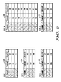
- a channel assignment tracker 138 determines, in response to the monitoring of channel assignments, a set of communication frequencies that have been assigned to wireless devices associated with the host/primary network 102. Based on the channels assigned by the host/primary network 102, the channel assignment tracker is able to determine the communication frequencies or range of channels that can be utilized by the secondary network 104. It should be noted that the term "spectrum" refers to channel frequencies that are used within a network for communication/data services. Examples of channel frequencies identified by the SCC 134 across various base stations of sites are illustrated in Figure 2 . Examples of channel frequencies identified by the channel assignment monitor 136 as being either assigned/unassigned are illustrated in Figure 3 .
- Figure 2 shows a table 202, 204, 206, 208, 210 for each monitored site/base station 116 in a primary network(s) 102.
- Each table 202, 204, 206, 208, 210 illustrates the frequency allocation used by the site within the host network.
- the table 202 for Site A indicates that Site A utilizes Channels 1-3.
- Channel 1 has a transmit frequency of T11 and a receive frequency of R11.
- Channel 2 has a transmit frequency of T2 and a receive frequency of R2.
- Channel 3 has a transmit frequency of T14 and a receive frequency of R14.
- the channel availability transmitter 140 transmits, in response to determinations by the channel assignment tracker 138, to the secondary network 104, a specification of unused communication frequencies within the plurality of communication frequencies.
- Figure 3 shows a table 302, 304, 306, 308, 310 for each of the sites in Figure 2 illustrating potentially available spectrum that can be utilized by the secondary network 102. It is important to note that channel assignments may not be contiguous and if a channel is deemed available, the adjacent spectrum below and above the channel to neighboring channels can also be utilized by a secondary network. For example, these tables show that the minimum frequency of the host/primary network 102 is n and the maximum frequency is n+x. As discussed above with respect to Figure 2 , the channel assignment monitor 136 has determined that the following frequencies T2, T11, T14, R2, R11, and R14 have been allocated to Site A and at some point may be available for use. The tables of Figure 3 also identify the delta, or separation, between each frequency. For example, the table 302 associated with Site A shows that the delta between T2 and T11 is 1.80 MHz.
- the channel assignment tracker 138 has also identified portions of the spectrum utilized by each of the sites of the host/primary network 102 that can potentially be used by the secondary network 104, as shown in Figure 3 .
- the spectrum between T2 and T11 corresponding to the delta of 1.80 MHz has been identified by the channel assignment tracker 138 as potential spectrum that can be utilized by the secondary network 104.
- Each of the rows in Figure 3 that include underlined values in the "delta" column such as row 303 illustrates potential spectrum that is not utilized by the system and that can be used by the secondary network 104.
- underlined numbers indicate potential blocks of spectrum that is not used by the host/primary network 102 and may be suitable for the secondary network 104.
- Figure 4 illustrates spectrum 400 that is allocated/non-allocated by the entire host/primary network comprising sites A, B, C, D, and E associated with the tables of Figure 2 and Figure 3 .
- Figure 4 shows the receiver and transmit frequency pairs separated by a guard band 402.
- the guard band 402 is 4 MHz wide and is located from T(n+j) 404 to R(n) 406 or the difference between the highest transmit frequency and the lowest receive frequency of the primary system.
- the host/primary network 102 comprises spectrum that can be utilized by the secondary network 104.
- the secondary network 104 determines the location of a "home" or "control" channel, perhaps in the guard band 402 or in some of the other identified holes.
- the "home" channel can be relocated or can grow or shrink in a contiguous and non-contiguous manner depending on the usage requirements of the host/primary network 102.
- the SCC 134 communicates spectrum information to the secondary network 104 via the link 107 (in this example).
- the channel assignment manager 128 of the secondary network 104 receives this information and determines the available frequencies in the host/primary network 102 that it can utilize.
- the secondary network 104 in one example, utilizes orthogonal frequency division multiplexing ("OFDM"), which is used to create a wideband modulus comprising a multiplicity of narrowband channels.
- OFDM orthogonal frequency division multiplexing
- the channel assignment manager 128 of the secondary network also establishes a home or control channel within spectrum that has the highest probability of going unused by the host/primary network such as in the guard band area 402 illustrated in Figure 4 .
- a control channel of the secondary network allows a wireless device to transmit call request, receive traffic channel assignments, and perform other similar functions.
- the SCC 134 includes a second channel assignment monitor 150 that determines the frequency or frequency ranges that are being utilized by the secondary network 104 as its control channel. The SCC 134 of that further embodiment then updates its channel assignment database 142 accordingly.
- the second channel assignments monitor 150 monitors the channel allocation commands and control information issued by the channel assignment manager 128 of the secondary network 104.
- the second channel assignment monitor 150 is adapted to accept a message from at least one secondary network 104 that comprises a second specification of communication frequencies from the plurality of communication frequencies that are not to be used by the host/primary network 102.
- Such operations by this further embodiment allow the SCC 134 to identify spectrum being utilized by the secondary network 104 and provide instructions to the host/primary network 102, in embodiments that support such instructions, to not use the spectrum currently used by the secondary network 104.
- a channel assignment manager 128 of a further embodiment is able to allocate a communication channel to the device 110 from the set of available communication frequencies identified by the SCC 134.
- the second channel assignment monitor 150 of this further embodiment detects this channel assignment and updates its channel assignment database 142 accordingly.
- a second channel availability transmitter 152 then transmits the specification of communication frequencies that are not to be used by the host/primary network 102 to the host/primary network 102.
- one embodiment of the present invention is advantageous in that it increases the overall spectral efficiency of networks by providing real-time coordinated use of common spectrum between separate networks incorporating potentially dissimilar networking technologies.
- One embodiment of the present invention monitors spectrum allocation commands and control information associated with an existing host/primary network to identify unused spectrum.
- One embodiment of the present invention then instructs a secondary network to utilize the unused spectrum by adapting to and scavenging spectrum not used by the host/primary network at any given time.
- the allocation commands associated with the host/primary network 102 monitored by the SCC 134 can also comprise commands indicating that a particular frequency or frequency range(s) is to be prevented from being utilized by the secondary network 104.
- the SCC 134 does not include that particular frequency or frequency range in the listing of available frequencies sent to the secondary network 104.
- the secondary network 104 can also issue a command that instructs the host/primary network 104 to not allocate a particular frequency or frequency range(s).
- the SCC 134 receives the command and instructs the host/primary network 102 accordingly.
- the available spectrum of the host/primary network 102 is dynamic. In other words, the available spectrum changes over time.
- a wireless device 108 at the host/primary network 102 can request a call setup.
- the call manager 124 at the host/primary network 102 and the channel assignment manager 124 allocates a particular channel to the device 108 to service that call. However, that channel may be currently in use by the secondary network 104.
- the SCC 134 detects an allocation command for that particular channel. Therefore, the SCC 134 issues a command to the secondary network 104 to de-allocate that channel. If the secondary system is using that channel, it is de-allocated by the secondary network 104. Hence, secondary use policies determining how the secondary network 104 utilizes the available spectrum can be enforced. In one embodiment, the secondary network 104 can be instructed to yield right-of-way to the host/primary network so that the host/primary network 102 gets priority over the use of the spectrum. It is obvious to those skilled in the art that other policies/etiquette can be developed and enforced. For example, the device 108 can issue an emergency call request that must be assigned immediately.
- Figure 5 shows a transactional diagram illustrating this process. Time is depicted in Figure 5 by the vertical scale.
- a wireless device 108 subscribing to the host/primary network 102 submits a call request 520 to its host base station 116.
- the call request 522 is sent to the host core 506 and the call request is granted at time T 2 .
- the channel assignment manager 124 of the host/primary network 102 allocates a channel to the requesting device 108.
- the SCC 134 at time T 3 , detects the channel assignment via an allocation command 528, which is monitored by the monitor link 106.
- the SCC 134 also instructs the base station 118 at the secondary network 104 to not use the channel.
- the base station 118 at the secondary network 104 performs the de-allocation of that channel.
- the base station 116 at the host/primary network 102 at time T 5 , initiates use of the channel.
- the wireless device 108 of the host/primary network 102 adjusts its synthesizer to the channel at time T 6 so that the call requested by the device 108 can be made.
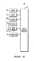
- FIG. 6 is a block diagram illustrating a detailed view of the wireless device 108, 110 according to one embodiment of the present invention. It is assumed that the reader is familiar with wireless communication devices. To simplify the present description, only that portion of a wireless communication device that is relevant to the present invention is discussed.
- the wireless device 108 operates under the control of a device controller/processor 602, that controls the sending and receiving of wireless communication signals. In receive mode, the device controller 602 electrically couples an antenna 604 through a transmit/receive switch 606 to a receiver 608. The receiver 608 decodes the received signals and provides those decoded signals to the device controller 602.
- the device controller 602 electrically couples the antenna 604, through the transmit/receive switch 606, to a transmitter 610.
- the receiver 608 and the transmitter 610 are a dual mode receiver and a dual mode transmitter for receiving/transmitting over various access networks providing different air interface types.
- a separate receiver and transmitter is used for each of type of air interface.
- the device controller 602 operates the transmitter and receiver according to instructions stored in the memory 612. These instructions include, for example, a neighbor cell measurement-scheduling algorithm.
- the wireless device 108 also includes non-volatile storage memory 614 for storing, for example, an application waiting to be executed (not shown) on the wireless device 108.
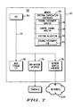
- FIG. 7 is a block diagram illustrating a more detailed view of an information processing system 132.
- the information processing system 132 includes a computer 702.
- the computer 702 has a CPU processor 704 that is connected to a main memory 706, a mass storage interface 708, a man-machine interface 710, and network adapter hardware 716.
- a system bus 714 interconnects these system components.
- the main memory 706 includes the SCC 134, which comprises a channel assignment monitor 136, a channel assignment tracker 138, a channel availability transmitter 140, a channel availability transmitter, a second channel assignment monitor 150, a second channel availability transmitter 152, and a channel assignment database 142, which have all been discussed in greater detail above.
- SCC 134 comprises a channel assignment monitor 136, a channel assignment tracker 138, a channel availability transmitter 140, a channel availability transmitter, a second channel assignment monitor 150, a second channel availability transmitter 152, and a channel assignment database 142, which have all been discussed in greater detail above.
- the main memory 706 also includes the channel assignment database 142. Although illustrated as concurrently resident in the main memory 706, it is clear that respective components of the main memory 706 are not required to be completely resident in the main memory 706 at all times or even at the same time. Furthermore, one or more of these components can be implemented as hardware.
- the mass storage interface 708 can store data on a hard-drive or media such as a CD or DVD.
- the man-machine interface 710 allows technicians, administrators, and other users to directly connect to the information processing system 130 via one or more terminals 718.
- the network adapter hardware 716 in one embodiment, is used to provide an interface to the communication network 112, 114.
- Embodiments of the present invention are able to be adapted to work with any data communications links, including present day analog and/or digital techniques or via a future networking mechanism.
- Figure 8 is an operational flow diagram illustrating a process of coordinating spectrum use between a host/primary network 102 and one or more secondary networks 104.
- the operational flow diagram of Figure 8 begins at step 801 and flows directly to step 802.
- the SCC 134 at step 802, analyzes the host/primary network 102 and determines the frequency spectrum being used within the network 102. In one embodiment, the SCC 134 can analyze initial data to help identify the host/primary network 102 that it is to center on. However, this is not required.
- the SCC at step 804, monitors the host/primary network 102 for allocation and de-allocation commands and control information.
- the SCC 134, at step 806, determines if an allocation command has been detected.
- the SCC 134 continues to monitor for allocation commands and control information. If the result of this determination is positive, the SCC 134, determines at step 807, if the host/primary network de-allocated a channel. If the host/primary network did de-allocate a channel, the processing continues by the SCC instructing, at step 808, the secondary controller to use the channel de-allocated by the host network. After such instruction, or if the SCC determined that the host/primary network did not de-allocate a channel, the SCC updates, at step 809, its channel assignment database 142.
- the SCC 134 determines a set of frequencies and/or frequency ranges that are currently unused at the host/primary network 102.
- the SCC 134 transmits the set of frequencies and/or frequency ranges to the secondary network 104.
- the host/primary network 102 can issue a command to base stations in that network that is monitored by the SCC 134 that indicates one or more frequencies or frequency ranges are used by the host network, and therefore are not to be utilized by the secondary network 104.
- the secondary network 104 receives the set of frequencies and/or frequency ranges and may designate one or more of the frequencies as a control/home channel.
- the SCC 134 assumes that all frequency ranges indicated to the secondary overly network 104 as available are used by that network.
- the SCC 134 is able to identify the frequency(s) utilized by the secondary network 104 designated as the control/home channel by, for example, monitoring assignments made by the secondary network 104.
- the SCC 134 at step 816, updates its channel assignment database 142 accordingly.
- the wireless subscribers 110 of the secondary network 104, at step 816 are also updated with the control/home channel information.
- the SCC 134 monitors the host/primary network 102 for channel assignments and updates its channel assignment database 142 accordingly. For example, if the SCC 134 detects that the host/primary network 102 has assigned a channel to a wireless device 108, the SCC 134 updates the channel assignment database. It should be noted that the SCC 134 is also continuing to monitor the channel assignments and deassignments at the host/primary network 102.
- the SCC 134 determines if the host/primary network 102 is allocating channels, which can be a home (control) or expansion channel (e.g., a channel used by the secondary network 104 as a traffic channel). If the result of this determination is negative, the SCC 134 continues to monitor for channel assignments/de-assignments by the host/primary network 102. If the result of this determination is positive, the control flows to entry point A of Figure 9 .
- the SCC 134 instructs the secondary network 104 that the channel is no longer available for use and must de-allocate that channel for its use.
- the secondary network 104 instructs the wireless device 110 assigned to that particular channel to vacate the channel. If the channel is a home/control channel then all of the wireless devices 110 subscribing to the secondary network 104 are instructed to vacate the channel.
- the wireless devices 110 at step 906, attempt to resynchronize with their new home channel.
- the wireless devices 110 determine if the home channel is available. If the result of this determination is positive, the control flows back to step 818 of Figure 8 . If the result of the determination is negative, the wireless devices 110, at step 910, await for home channel allocation instructions from the secondary network 104. Once instructions are received the wireless devices try to synchronize with the new home channel at step 908.
- the site controller 122 of the secondary system 104 determines if another channel is available for the secondary network 104 to use as a home channel.
- the secondary network 104 at step 916, notifies its wireless subscribers 110 that spectrum from the host/primary network 104 is not going to be used.
- the control flow returns to step 906. If the result of the determination at step 912 is positive, the wireless subscribers 110 of the secondary network 104, at step 920, proceed to use the indicated channel or channels.
Landscapes
- Engineering & Computer Science (AREA)
- Computer Networks & Wireless Communication (AREA)
- Signal Processing (AREA)
- Mobile Radio Communication Systems (AREA)
Description
- The present invention generally relates to the field of wireless communications, and more particularly relates to managing allocation of communication frequencies available in a host/primary network to one or more secondary networks.
- Wireless communication technology has evolved greatly over the recent years. Wireless communication networks can include a variety of different network technologies. Furthermore, one wireless communication network may comprise underused spectrum that another wireless communication network can utilize on a secondary basis. Traditionally, wireless communication technology allows for systems to co-exist independently while sharing a common resource, such as spectrum. However, traditional wireless communication systems do not coordinate the use of the spectrum. Interoperability of systems using the same spectrum can be resolved, for example, through cooperative operation among network devices, e.g., synchronization and spatial scheduling can be employed to mitigate interference associated with network operation.
- In situations in which two dissimilar network solutions/technologies are co-located such as a network installed some time ago at a fixed geographic location that can serve as a host for a newly installed second network, the systems do not coordinate the use of critical system resources such as spectrum. Furthermore, the first system may be the primary licensed system that was allocated the spectrum and the second system may be licensed to use the spectrum on a secondary basis; namely, allowed to use the spectrum provided that harmful interference does not degrade the performance of the primary licensed system. However, current technology generally does not provide an efficient and advantageous way for maintaining proper synchronization and critical time-aligned operations between the secondary and the host/primary networks for mitigating harmful interference to the host/primary network. For example, current technologies generally do not provide a system in which the operation of a secondary network, i.e., a network that co-exists with an existing system, includes yielding spectrum right-of-way when spectrum scavenged by the secondary network is "recalled" by the host/primary network.
-
US 2007/195731 A1 discloses to detect an unused channel assigned to a cellular network and to use the free channel for P2P-communication. - Therefore a need exists to overcome the problems with the prior art as discussed above.
- A method that defines communication channel allocation is disclosed. The method includes monitoring communication channel allocation commands associated with a first network. The first network comprises a plurality of communication frequencies assigned by the communication channel allocation commands. A set of communication frequencies are determined that have been assigned to wireless devices associated with the first network in response to the monitoring. A specification of unused communication frequencies within the plurality of communication frequencies are transmitted to a second network in response to the determining.
- In another embodiment, a wireless communication controller is disclosed. The wireless communication controller includes a channel assignment monitor adapted to monitor communication channel allocation commands associated with a first network. The first network comprises a plurality of communication frequencies assigned by communication channel allocation commands. A channel assignment tracker is communicatively coupled to the channel assignment monitor. The channel assignment tracker is adapted to determine, in response to monitoring by the channel assignment monitor, a set of communication frequencies that have been assigned to wireless devices associated with the first network. A channel availability transmitter is communicatively coupled to the channel assignment tracker. The channel availability transmitter is adapted to transmit, in response to determinations by the channel assignment tracker, to a second network, a specification of unused communication frequencies within the plurality of communication frequencies.
- In yet another embodiment, an information processing system is disclosed. The information processing system includes a memory and a processor that is communicatively coupled to the memory. The information processing system also includes a wireless communication controller that is communicatively coupled to the memory and the processor. The wireless communication controller includes a channel assignment monitor adapted to monitor communication channel allocation commands associated with a first network. The first network comprises a plurality of communication frequencies assigned by the communication channel allocation commands. A channel assignment tracker is communicatively coupled to the channel assignment monitor. The channel assignment tracker is adapted to determine, in response to monitoring by the channel assignment monitor, a set of communication frequencies that have been assigned to wireless devices associated with the first network. A channel availability transmitter is communicatively coupled to the channel assignment tracker. The channel availability transmitter is adapted to transmit, in response to determinations by the channel assignment tracker, to a second network, a specification of unused communication frequencies within the plurality of communication frequencies.
- An advantage of the various embodiments of the present invention is that the allocation of available spectrum in one wireless communication network to one or more additional wireless communication networks is coordinated. This coordination prevents the degradation of service quality of the host incumbent primary network. The various embodiments of the present invention also maintain proper synchronization and critical time-aligned operations between the host/primary and the secondary networks to mitigate harmful interference to the host/primary network. The various embodiments of the present invention also increase the overall spectral efficiency of the shared spectrum.
- The accompanying figures where like reference numerals refer to identical or functionally similar elements throughout the separate views, and which together with the detailed description below are incorporated in and form part of the specification, serve to further illustrate various embodiments and to explain various principles and advantages all in accordance with the present invention.
-
Figure 1 is block diagram illustrating a wireless communication system, according to one embodiment of the present invention; -
Figure 2 illustrates examples of identified communication frequencies across various base stations of sites, according to one embodiment of the present invention; -
Figure 3 illustrates examples of communication frequencies identified by a channel assignment monitor as being either assigned/unassigned at each of the communication sites ofFigure 2 , according to one embodiment of the present invention; -
Figure 4 is a frequency spectrum illustrating the allocated/non-allocated spectrum across the various sites associated with the tables ofFigure 2 andFigure 3 , according to one embodiment of the present invention; -
Figure 5 is a transactional diagram illustrating the process accommodating a host/primary network allocating a communication channel currently being utilized by a secondary network, according to one embodiment of the present invention; -
Figure 6 is a block diagram illustrating a detailed view of a wireless device according to one embodiment of the present invention; -
Figure 7 is a block diagram illustrating a detailed view of an information processing system, according to one embodiment of the present invention; and -
Figures 8 and9 are operational flow diagrams illustrating a process of coordinating the allocation of unused spectrum between a host/primary network and a secondary network, according to one embodiment of the present invention. - As required, detailed embodiments of the present invention are disclosed herein; however, it is to be understood that the disclosed embodiments are merely examples of the invention, which can be embodied in various forms. Therefore, specific structural and functional details disclosed herein are not to be interpreted as limiting, but merely as a basis for the claims and as a representative basis for teaching one skilled in the art to variously employ the present invention in virtually any appropriately detailed structure. Further, the terms and phrases used herein are not intended to be limiting; but rather, to provide an understandable description of the invention.
- The terms "a" or "an", as used herein, are defined as one or more than one. The term plurality, as used herein, is defined as two or more than two. The term another, as used herein, is defined as at least a second or more. The terms including and/or having, as used herein, are defined as comprising (i.e., open language). The term coupled, as used herein, is defined as connected, although not necessarily directly, and not necessarily mechanically.
- The term "wireless device" is intended to broadly cover many different types of devices that can wirelessly receive signals, and optionally can wirelessly transmit signals, and may also operate in a wireless communication system. For example, and not for any limitation, a wireless communication device can include (but is not limited to) any one or a combination of the following: a two-way radio, a cellular telephone, a mobile phone, a smartphone, a two-way pager, a wireless messaging device, a laptop/computer, automotive gateway, or a residential gateway.
- According to one embodiment of the present invention as shown in
Figure 1 awireless communication system 100 is illustrated.Figure 1 shows a plurality ofnetworks networks wireless communication system 100 can comprise additional networks. In one embodiment, one of thenetworks 102 is a host/primary network and one or more of the additional networks aresecondary networks 104. In one embodiment, a host/primary network can be an underlay network and a secondary network can be an overlay network. The host/primary network 102 is assigned RF spectrum that is divided into channels that can potentially be used by the secondary network(s) 104. Throughout this discussion the terms "host" and "primary" that refer to, for example, host/primary network 102, are used interchangeably. - Each of the
wireless communication networks more communication networks communication networks communication networks wired communication networks - The wireless communications standard of the
networks coupling bases stations mobiles 108/110 can comprise Code Division Multiple Access ("CDMA"), Time Division Multiple Access ("TDMA"), Global System for Mobile Communications ("GSM"), General Packet Radio Service ("GPRS"), Frequency Division Multiple Access ("FDMA"), other IEEE 802.16 standards, Orthogonal Frequency Division Multiplexing ("OFDM"), Orthogonal Frequency Division Multiple Access ("OFDMA"), Wireless LAN ("WLAN"), WiMAX, or the like. Thewireless communications networks - A circuit services network is able to provide, among other things, voice services to the
wireless devices networks primary network 102 providing Land Mobile Radio System ("LMRS") services such as P25 Trunking and asecondary network 104 providing WiMAX communication system services. It should be noted that these network technologies are only used as an illustrative example and do not limit further embodiments of the present invention. - Each of the wireless communication networks includes a plurality of
base stations base stations information processing system site controller controllers channel assignment manager call manager channel assignment manager call manager wireless communication system 100 also includes one or moreinformation processing systems 132 that monitor control messages, such as channel assignment and de-assignment messages sent between thechannel assignment manager 124 of the host/primary network 102 and thebase stations 116 of the host/primary network 102. These control messages can be intercepted by theinformation processing system 132 or interact with an interface to thesite controller 120 such as (but not limited to) an API or a billing interface to monitor assignment information. - It should be noted that, in one embodiment, the functions of the information processing system(s) 132 can also be implemented at the
Host site controller 120. In one embodiment, the control messages are sent through thewired communication network 112 and passively monitored by amonitor link 106. It should be noted that themonitor link 106 can be wireless or wired (such as fiber optic). - The
information processing system 132, in one embodiment, includes one or more spectrum coordination controllers ("SCC") 134 that coordinates the allocation of available spectrum/communication frequencies not used by the host/primary network 102 to thesecondary network 104. Theinformation processing system 132 includes a computer program storage medium that includes achannel assignment monitor 136, achannel assignment tracker 138, achannel availability transmitter 140, a secondchannel assignment monitor 150, a secondchannel availability transmitter 152, and achannel assignment database 142. TheSCC 134 and each of its components are discussed in greater detail below. Specifications of channels that are unassigned by the host/primary network 102 are communicated to thesecondary network 104 through adata link 107. It should be noted that the data link 107 can be wireless or wired (such as fiber optic). - As discussed above, in one example, the existing host/
primary network 102 is a narrowband voice system (e.g., P25 LMRS) and thesecondary network 104 is a wide band data-centric solution used to transport content such as video (e.g., WiMAX). In one example, the host/primary network 102 follows a given channel filling algorithm for allocating communication frequencies. For example, channel selection can start from the low end of the band to the high end of the band or vice versa. TheSCC 134 of one embodiment, as discussed above, is communicatively coupled to both the host/primary network 102 and thesecondary network 104 so as to allow theSCC 134 to monitor control messages of the host/primary network 102 and provide available spectrum information to thesecondary network 104. - The channel assignment monitor 136 monitors spectrum/communication channel allocations at the host/
primary network 102. For example, the channel assignment monitor 136 monitors for and detects channel allocation and de-allocation commands, which are generally referred to herein as channel allocation commands, issued by thechannel assignment manager 124 at the host/primary network 102. TheSCC 134 analyzes the monitored channel allocation and de-allocation information and stores the information in achannel assignment database 142. For example, theSCC 134 determines which communication frequencies are currently assigned/unassigned in the host/primary network 102 and tracks these assignments via thechannel assignment database 142. - A
channel assignment tracker 138 determines, in response to the monitoring of channel assignments, a set of communication frequencies that have been assigned to wireless devices associated with the host/primary network 102. Based on the channels assigned by the host/primary network 102, the channel assignment tracker is able to determine the communication frequencies or range of channels that can be utilized by thesecondary network 104. It should be noted that the term "spectrum" refers to channel frequencies that are used within a network for communication/data services. Examples of channel frequencies identified by theSCC 134 across various base stations of sites are illustrated inFigure 2 . Examples of channel frequencies identified by the channel assignment monitor 136 as being either assigned/unassigned are illustrated inFigure 3 .Figure 2 shows a table 202, 204, 206, 208, 210 for each monitored site/base station 116 in a primary network(s) 102. Each table 202, 204, 206, 208, 210 illustrates the frequency allocation used by the site within the host network. For example, the table 202 for Site A indicates that Site A utilizes Channels 1-3.Channel 1 has a transmit frequency of T11 and a receive frequency of R11.Channel 2 has a transmit frequency of T2 and a receive frequency of R2. Channel 3 has a transmit frequency of T14 and a receive frequency of R14. - Once the
SCC 134 determines the spectrum in use (or not in use) by the host/primary network 102, thechannel availability transmitter 140 transmits, in response to determinations by thechannel assignment tracker 138, to thesecondary network 104, a specification of unused communication frequencies within the plurality of communication frequencies. -
Figure 3 shows a table 302, 304, 306, 308, 310 for each of the sites inFigure 2 illustrating potentially available spectrum that can be utilized by thesecondary network 102. It is important to note that channel assignments may not be contiguous and if a channel is deemed available, the adjacent spectrum below and above the channel to neighboring channels can also be utilized by a secondary network. For example, these tables show that the minimum frequency of the host/primary network 102 is n and the maximum frequency is n+x. As discussed above with respect toFigure 2 , the channel assignment monitor 136 has determined that the following frequencies T2, T11, T14, R2, R11, and R14 have been allocated to Site A and at some point may be available for use. The tables ofFigure 3 also identify the delta, or separation, between each frequency. For example, the table 302 associated with Site A shows that the delta between T2 and T11 is 1.80 MHz. - The
channel assignment tracker 138 has also identified portions of the spectrum utilized by each of the sites of the host/primary network 102 that can potentially be used by thesecondary network 104, as shown inFigure 3 . For example, the spectrum between T2 and T11 corresponding to the delta of 1.80 MHz has been identified by thechannel assignment tracker 138 as potential spectrum that can be utilized by thesecondary network 104. Each of the rows inFigure 3 that include underlined values in the "delta" column such asrow 303 illustrates potential spectrum that is not utilized by the system and that can be used by thesecondary network 104. In particular, underlined numbers indicate potential blocks of spectrum that is not used by the host/primary network 102 and may be suitable for thesecondary network 104. -
Figure 4 illustrates spectrum 400 that is allocated/non-allocated by the entire host/primary network comprising sites A, B, C, D, and E associated with the tables ofFigure 2 andFigure 3 .Figure 4 shows the receiver and transmit frequency pairs separated by aguard band 402. In the n to n+x band, theguard band 402 is 4 MHz wide and is located from T(n+j) 404 to R(n) 406 or the difference between the highest transmit frequency and the lowest receive frequency of the primary system. As can be seen fromFigure 4 , the host/primary network 102 comprises spectrum that can be utilized by thesecondary network 104. Thesecondary network 104 determines the location of a "home" or "control" channel, perhaps in theguard band 402 or in some of the other identified holes. Thus, in real-time the "home" channel can be relocated or can grow or shrink in a contiguous and non-contiguous manner depending on the usage requirements of the host/primary network 102. - The
SCC 134 communicates spectrum information to thesecondary network 104 via the link 107 (in this example). Thechannel assignment manager 128 of thesecondary network 104 receives this information and determines the available frequencies in the host/primary network 102 that it can utilize. As discussed above, thesecondary network 104, in one example, utilizes orthogonal frequency division multiplexing ("OFDM"), which is used to create a wideband modulus comprising a multiplicity of narrowband channels. A single narrowband channel can occupy the same amount of bandwidth required to support a single narrowband voice channel of the host/primary network 102, thereby facilitating filling of the band on a per channel basis. - The
channel assignment manager 128 of the secondary network also establishes a home or control channel within spectrum that has the highest probability of going unused by the host/primary network such as in theguard band area 402 illustrated inFigure 4 . A control channel of the secondary network allows a wireless device to transmit call request, receive traffic channel assignments, and perform other similar functions. In a further embodiment, theSCC 134 includes a second channel assignment monitor 150 that determines the frequency or frequency ranges that are being utilized by thesecondary network 104 as its control channel. TheSCC 134 of that further embodiment then updates itschannel assignment database 142 accordingly. For example, the second channel assignments monitor 150 monitors the channel allocation commands and control information issued by thechannel assignment manager 128 of thesecondary network 104. In other words, the second channel assignment monitor 150 is adapted to accept a message from at least onesecondary network 104 that comprises a second specification of communication frequencies from the plurality of communication frequencies that are not to be used by the host/primary network 102. Such operations by this further embodiment allow theSCC 134 to identify spectrum being utilized by thesecondary network 104 and provide instructions to the host/primary network 102, in embodiments that support such instructions, to not use the spectrum currently used by thesecondary network 104. - When the
call manager 130 of thesecondary network 104 receives a call request from awireless device 110, achannel assignment manager 128 of a further embodiment is able to allocate a communication channel to thedevice 110 from the set of available communication frequencies identified by theSCC 134. The second channel assignment monitor 150 of this further embodiment detects this channel assignment and updates itschannel assignment database 142 accordingly. A secondchannel availability transmitter 152 then transmits the specification of communication frequencies that are not to be used by the host/primary network 102 to the host/primary network 102. - As can be seen, one embodiment of the present invention is advantageous in that it increases the overall spectral efficiency of networks by providing real-time coordinated use of common spectrum between separate networks incorporating potentially dissimilar networking technologies. One embodiment of the present invention monitors spectrum allocation commands and control information associated with an existing host/primary network to identify unused spectrum. One embodiment of the present invention then instructs a secondary network to utilize the unused spectrum by adapting to and scavenging spectrum not used by the host/primary network at any given time.
- In a further embodiment, it should be noted that the allocation commands associated with the host/
primary network 102 monitored by theSCC 134 can also comprise commands indicating that a particular frequency or frequency range(s) is to be prevented from being utilized by thesecondary network 104. In such one embodiment, theSCC 134 does not include that particular frequency or frequency range in the listing of available frequencies sent to thesecondary network 104. In one embodiment, thesecondary network 104 can also issue a command that instructs the host/primary network 104 to not allocate a particular frequency or frequency range(s). TheSCC 134, in this embodiment, receives the command and instructs the host/primary network 102 accordingly. - As discussed above, the available spectrum of the host/
primary network 102 is dynamic. In other words, the available spectrum changes over time. For example, awireless device 108 at the host/primary network 102 can request a call setup. Thecall manager 124 at the host/primary network 102 and thechannel assignment manager 124 allocates a particular channel to thedevice 108 to service that call. However, that channel may be currently in use by thesecondary network 104. - In one embodiment, the
SCC 134 detects an allocation command for that particular channel. Therefore, theSCC 134 issues a command to thesecondary network 104 to de-allocate that channel. If the secondary system is using that channel, it is de-allocated by thesecondary network 104. Hence, secondary use policies determining how thesecondary network 104 utilizes the available spectrum can be enforced. In one embodiment, thesecondary network 104 can be instructed to yield right-of-way to the host/primary network so that the host/primary network 102 gets priority over the use of the spectrum. It is obvious to those skilled in the art that other policies/etiquette can be developed and enforced. For example, thedevice 108 can issue an emergency call request that must be assigned immediately. If these two systems (host 102 and secondary 104) know about each other they can reserve the other's spectrum during normal conditions, but if an emergency call was needed and the host/primary network 102 does not have any available channels, thesecondary network 104 releases any reserved spectrum in the host/primary network 104 -
Figure 5 shows a transactional diagram illustrating this process. Time is depicted inFigure 5 by the vertical scale. At time T0, awireless device 108 subscribing to the host/primary network 102 submits acall request 520 to itshost base station 116. At time T1, thecall request 522 is sent to thehost core 506 and the call request is granted at time T2. At time T3, thechannel assignment manager 124 of the host/primary network 102 allocates a channel to the requestingdevice 108. TheSCC 134, at time T3,, detects the channel assignment via anallocation command 528, which is monitored by themonitor link 106. At time T3', theSCC 134 also instructs thebase station 118 at thesecondary network 104 to not use the channel. In the event that thesecondary network 104 was using the channel, thebase station 118 at thesecondary network 104, at time T4, performs the de-allocation of that channel. Thebase station 116 at the host/primary network 102, at time T5, initiates use of the channel. Thewireless device 108 of the host/primary network 102 adjusts its synthesizer to the channel at time T6 so that the call requested by thedevice 108 can be made. -
Figure 6 is a block diagram illustrating a detailed view of thewireless device wireless device 108 operates under the control of a device controller/processor 602, that controls the sending and receiving of wireless communication signals. In receive mode, thedevice controller 602 electrically couples anantenna 604 through a transmit/receiveswitch 606 to areceiver 608. Thereceiver 608 decodes the received signals and provides those decoded signals to thedevice controller 602. - In transmit mode, the
device controller 602 electrically couples theantenna 604, through the transmit/receiveswitch 606, to atransmitter 610. It should be noted that in one embodiment, thereceiver 608 and thetransmitter 610 are a dual mode receiver and a dual mode transmitter for receiving/transmitting over various access networks providing different air interface types. In another embodiment a separate receiver and transmitter is used for each of type of air interface. - The
device controller 602 operates the transmitter and receiver according to instructions stored in thememory 612. These instructions include, for example, a neighbor cell measurement-scheduling algorithm. Thewireless device 108, also includesnon-volatile storage memory 614 for storing, for example, an application waiting to be executed (not shown) on thewireless device 108. -
Figure 7 is a block diagram illustrating a more detailed view of aninformation processing system 132. It should be noted that although the following discussion is with respect to theinformation processing system 130 comprising theSCC 134, theinformation processing system 132 is based upon a suitably configured processing system adapted to implement one embodiment of the present invention. For example, a personal computer, workstation, or the like, may be used. Theinformation processing system 132 includes acomputer 702. Thecomputer 702 has aCPU processor 704 that is connected to amain memory 706, amass storage interface 708, a man-machine interface 710, andnetwork adapter hardware 716. Asystem bus 714 interconnects these system components. - The
main memory 706 includes theSCC 134, which comprises achannel assignment monitor 136, achannel assignment tracker 138, achannel availability transmitter 140, a channel availability transmitter, a secondchannel assignment monitor 150, a secondchannel availability transmitter 152, and achannel assignment database 142, which have all been discussed in greater detail above. - The
main memory 706 also includes thechannel assignment database 142. Although illustrated as concurrently resident in themain memory 706, it is clear that respective components of themain memory 706 are not required to be completely resident in themain memory 706 at all times or even at the same time. Furthermore, one or more of these components can be implemented as hardware. - The
mass storage interface 708 can store data on a hard-drive or media such as a CD or DVD. The man-machine interface 710 allows technicians, administrators, and other users to directly connect to theinformation processing system 130 via one or more terminals 718. Thenetwork adapter hardware 716, in one embodiment, is used to provide an interface to thecommunication network -
Figure 8 is an operational flow diagram illustrating a process of coordinating spectrum use between a host/primary network 102 and one or moresecondary networks 104. The operational flow diagram ofFigure 8 begins atstep 801 and flows directly to step 802. TheSCC 134, atstep 802, analyzes the host/primary network 102 and determines the frequency spectrum being used within thenetwork 102. In one embodiment, theSCC 134 can analyze initial data to help identify the host/primary network 102 that it is to center on. However, this is not required. The SCC, atstep 804, monitors the host/primary network 102 for allocation and de-allocation commands and control information. TheSCC 134, atstep 806, determines if an allocation command has been detected. If the result of this determination is negative, theSCC 134 continues to monitor for allocation commands and control information. If the result of this determination is positive, theSCC 134, determines atstep 807, if the host/primary network de-allocated a channel. If the host/primary network did de-allocate a channel, the processing continues by the SCC instructing, atstep 808, the secondary controller to use the channel de-allocated by the host network. After such instruction, or if the SCC determined that the host/primary network did not de-allocate a channel, the SCC updates, atstep 809, itschannel assignment database 142. - The
SCC 134, at step 810, determines a set of frequencies and/or frequency ranges that are currently unused at the host/primary network 102. TheSCC 134, atstep 812, transmits the set of frequencies and/or frequency ranges to thesecondary network 104. As discussed above, the host/primary network 102 can issue a command to base stations in that network that is monitored by theSCC 134 that indicates one or more frequencies or frequency ranges are used by the host network, and therefore are not to be utilized by thesecondary network 104. - The
secondary network 104, atstep 813, receives the set of frequencies and/or frequency ranges and may designate one or more of the frequencies as a control/home channel. In one embodiment, theSCC 134 assumes that all frequency ranges indicated to the secondary overlynetwork 104 as available are used by that network. In further embodiments, theSCC 134 is able to identify the frequency(s) utilized by thesecondary network 104 designated as the control/home channel by, for example, monitoring assignments made by thesecondary network 104. In either embodiment, theSCC 134, at step 816, updates itschannel assignment database 142 accordingly. Thewireless subscribers 110 of thesecondary network 104, at step 816, are also updated with the control/home channel information. - The
SCC 134, atstep 818, monitors the host/primary network 102 for channel assignments and updates itschannel assignment database 142 accordingly. For example, if theSCC 134 detects that the host/primary network 102 has assigned a channel to awireless device 108, theSCC 134 updates the channel assignment database. It should be noted that theSCC 134 is also continuing to monitor the channel assignments and deassignments at the host/primary network 102. TheSCC 134, atstep 820, determines if the host/primary network 102 is allocating channels, which can be a home (control) or expansion channel (e.g., a channel used by thesecondary network 104 as a traffic channel). If the result of this determination is negative, theSCC 134 continues to monitor for channel assignments/de-assignments by the host/primary network 102. If the result of this determination is positive, the control flows to entry point A ofFigure 9 . - The
SCC 134, atstep 902, instructs thesecondary network 104 that the channel is no longer available for use and must de-allocate that channel for its use. Thesecondary network 104, atstep 904, instructs thewireless device 110 assigned to that particular channel to vacate the channel. If the channel is a home/control channel then all of thewireless devices 110 subscribing to thesecondary network 104 are instructed to vacate the channel. Thewireless devices 110, atstep 906, attempt to resynchronize with their new home channel. Thewireless devices 110, atstep 908, determine if the home channel is available. If the result of this determination is positive, the control flows back to step 818 ofFigure 8 . If the result of the determination is negative, thewireless devices 110, atstep 910, await for home channel allocation instructions from thesecondary network 104. Once instructions are received the wireless devices try to synchronize with the new home channel atstep 908. - When the
SCC 134 instructs thesecondary network 104 to de-allocate the channel or channels at issue, thesite controller 122 of thesecondary system 104, atstep 912, determines if another channel is available for thesecondary network 104 to use as a home channel. Thesecondary network 104, atstep 916, notifies itswireless subscribers 110 that spectrum from the host/primary network 104 is not going to be used. The control flow returns to step 906. If the result of the determination atstep 912 is positive, thewireless subscribers 110 of thesecondary network 104, atstep 920, proceed to use the indicated channel or channels. The control flows back to step 818 ofFigure 8 . It should be noted that after theSCC 134 instructs thesecondary network 104 to de-allocate the channel or channels at issue, thesecondary network 104 can determine select a new channel(s) to use. - Although specific embodiments of the invention have been disclosed, those having ordinary skill in the art will understand that changes can be made to the specific embodiments without departing from the scope of the invention. The scope of the invention is not to be restricted, therefore, to the specific embodiments, and it is intended that the appended claims cover any and all such applications, modifications, and embodiments within the scope of the present invention.
Claims (15)
- A method for defining communication channel allocation, the method comprising:monitoring (804) communication channel allocation commands associated with a first network, wherein the first network comprises a plurality of communication frequencies assigned by the communication channel allocation commands;determining (809), in response to the monitoring, a set of communication frequencies that have been assigned to wireless devices associated with the first network; andtransmitting (812), in response to the determining, to a second network, a specification of unused communication frequencies within the plurality of communication frequencies.
- The method of claim 1 wherein the communication channel allocation commands are communicated among at least some components of the first network via a wired link.
- The method of claim 1 further comprising:accepting a message from the second network comprising a second specification of communication frequencies from the plurality of communication frequencies that are not to be used by the first network; andtransmitting the specification of communication frequencies that are not to be used by the first network to the first network.
- The method of claim 1 wherein the second network accepts the specification of unused communication frequencies and assigns one of the unused communication frequencies to a wireless device associated with the second network.
- The method of claim 1 wherein the wireless communication controller associated with the second network accepts the specification of unused communication frequencies and designates an unused communication channel as a wirelessly exchanging control channel for the second network.
- The method of claim 1 further comprising:determining, based on the monitoring, that the first network has allocated a communication channel within the specification of unused communication frequencies; andnotifying the second network of an unavailability of the unused communication channel.
- The method of claim 6 further comprising:determining by the second network in response to the notifying, that the unused communication channel is assigned by the first network; andde-allocating by the second network, in response to the determining, the unused communication channel assigned by the first network.
- The method of claim 1 further comprising:receiving, in response to the transmitting, a request from the second network, to reserve a communication channel in the plurality of communication frequencies; andinstructing, in response to the receiving, the first network to reserve the communication channel.
- A wireless communication controller comprising:a channel assignment monitor (136) adapted to monitor communication channel allocation commands associated with a first network, wherein the first network comprises a plurality of communication frequencies assigned by the communication channel allocation commands;a channel assignment tracker (138), communicatively coupled to the channel assignment monitor, adapted to determine, in response to monitoring by the channel assignment monitor, a set of communication frequencies that have been assigned to wireless devices associated with the first network; anda channel availability transmitter (140) communicatively coupled to the channel assignment tracker, adapted to transmit, in response to determinations by the channel assignment tracker, to a second network, a specification of unused communication frequencies within the plurality of communication frequencies.
- The wireless communications controller of claim 9 wherein the communication channel allocation commands are communicated among at least some components of the first network via a wired link, and wherein the channel assignment monitor is adapted to monitor the wired link.
- The wireless communications controller of claim 9 further comprising:a second channel assignment monitor, communicatively coupled to the channel assignment tracker, adapted to accept a message from the second network comprising a second specification of communication frequencies from the plurality of communication frequencies that are not to be used by the first network; anda second channel availability transmitter, communicatively coupled to the second channel assignment monitor, adapted to transmit the specification of communication frequencies that are not to be used by the first network to the first network.
- The wireless communications controller of claim 9 wherein the second network accepts the specification of unused communication frequencies and assigns one of the unused communication frequencies to a wireless device associated with the second network.
- The wireless communications controller of claim 9 wherein a wireless communication controller associated with the second network accepts the specification of unused communication frequencies and designates an unused communication channel as a wirelessly exchanging control channel for the second network.
- The wireless communications controller of claim 9:wherein the channel assignment tracker is further adapted to determine, based on the monitoring, that the first network has allocated a communication channel within the specification of unused communication frequencies, andwherein the channel availability transmitter is further adapted to notify the second network of an unavailability of the unused communication channel.
- The wireless communications controller of claim 9 further comprising:a second channel assignment monitor, communicatively coupled to the channel assignment tracker, adapted to receive a request from the second network to reserve a communication channel in the plurality of communication frequencies; anda second channel availability transmitter, communicatively coupled to the second channel assignment monitor and the channel assignment tracker, adapted to instruct the first network to reserve the least one communication channel.
Applications Claiming Priority (2)
| Application Number | Priority Date | Filing Date | Title |
|---|---|---|---|
| US11/946,247 US8040815B2 (en) | 2007-11-28 | 2007-11-28 | Spectrum coordination controller |
| PCT/US2008/079360 WO2009070386A1 (en) | 2007-11-28 | 2008-10-09 | Spectrum coordination controller |
Publications (2)
| Publication Number | Publication Date |
|---|---|
| EP2215865A1 EP2215865A1 (en) | 2010-08-11 |
| EP2215865B1 true EP2215865B1 (en) | 2014-07-16 |
Family
ID=40340728
Family Applications (1)
| Application Number | Title | Priority Date | Filing Date |
|---|---|---|---|
| EP08853871.5A Active EP2215865B1 (en) | 2007-11-28 | 2008-10-09 | Spectrum coordination controller |
Country Status (3)
| Country | Link |
|---|---|
| US (1) | US8040815B2 (en) |
| EP (1) | EP2215865B1 (en) |
| WO (1) | WO2009070386A1 (en) |
Families Citing this family (22)
| Publication number | Priority date | Publication date | Assignee | Title |
|---|---|---|---|---|
| EP2215872B1 (en) * | 2007-11-29 | 2012-08-29 | Tridinetworks | Design and control systems, commissioning tools, configuration adapters and method for wireless and wired networks design, installation and automatic formation |
| JP5067866B2 (en) * | 2008-01-08 | 2012-11-07 | キヤノン株式会社 | Communication apparatus and control method |
| US8305917B2 (en) * | 2009-03-23 | 2012-11-06 | Motorola Solutions, Inc. | System and method for maintaining a backup radio operating parameter list in a secondary use communication system |
| US8521087B2 (en) * | 2009-07-15 | 2013-08-27 | Lg Electronics Inc. | System and method for cognitive radio transmission |
| US8750886B2 (en) * | 2010-05-06 | 2014-06-10 | Nokia Corporation | Apparatus and method for dynamic resolution of secondary communication system resources |
| US8711721B2 (en) * | 2010-07-15 | 2014-04-29 | Rivada Networks Llc | Methods and systems for dynamic spectrum arbitrage |
| TWI524799B (en) | 2010-10-12 | 2016-03-01 | 內數位專利控股公司 | TV idle frequency channel selection and network configuration service-based approach |
| WO2012072118A1 (en) * | 2010-11-30 | 2012-06-07 | Nokia Siemens Networks Oy | Dynamic spectrum refarming with multiple carriers |
| EP2684413B1 (en) * | 2011-03-10 | 2015-05-13 | Koninklijke Philips N.V. | Spectrum reallocation with prioritized schedule |
| EP2561638B1 (en) * | 2011-06-04 | 2014-07-23 | Ofinno Technologies, LLC | Enhanced multicarrier transmission using carrier aggregation |
| US9504034B2 (en) * | 2011-07-05 | 2016-11-22 | Tait Limited | Overlay of bearers in a radio communication system |
| FR2979045B1 (en) * | 2011-08-09 | 2013-09-20 | Cassidian | METHOD OF RADIOELECTRIC COEXISTENCE BETWEEN TWO PMR DEVICES, ONE OF WHICH IS IN NARROW BAND AND THE OTHER WITH BROADBAND |
| US9143291B2 (en) | 2012-12-27 | 2015-09-22 | Google Technology Holdings LLC | Method and apparatus for device-to-device communication |
| US9042938B2 (en) | 2012-12-27 | 2015-05-26 | Google Technology Holdings LLC | Method and apparatus for device-to-device communication |
| US9185697B2 (en) | 2012-12-27 | 2015-11-10 | Google Technology Holdings LLC | Method and apparatus for device-to-device communication |
| KR20160061904A (en) * | 2013-02-22 | 2016-06-01 | 리바다 네트웍스 엘엘씨 | Methods and systems for dynamic spectrum arbitrage |
| US9370035B2 (en) | 2013-08-12 | 2016-06-14 | Google Technology Holdings LLC | Methods and devices for mobile station device-to-device beacon window determination |
| US9392615B2 (en) | 2013-08-20 | 2016-07-12 | Google Technology Holdings LLC | Methods and devices for allocating resources in device-to-device communication |
| US20170078896A1 (en) * | 2015-09-11 | 2017-03-16 | Laird Technologies, Inc. | Using network-provided information to tune wireless network client performance |
| US10123309B2 (en) * | 2016-12-06 | 2018-11-06 | Cisco Technology, Inc. | System and method for discovery and acquisition of a control channel using guard bands |
| US10772052B2 (en) * | 2017-06-16 | 2020-09-08 | Qualcomm Incorporated | Controlling coexistent radio systems in a wireless device |
| US20240147320A1 (en) * | 2022-11-02 | 2024-05-02 | At&T Intellectual Property I, L.P. | Method and system for channel coordination in network core and cbrs |
Family Cites Families (25)
| Publication number | Priority date | Publication date | Assignee | Title |
|---|---|---|---|---|
| GB2214758A (en) * | 1988-01-22 | 1989-09-06 | Philips Electronic Associated | Signal distribution network system |
| US5040238A (en) * | 1990-06-29 | 1991-08-13 | Motorola, Inc. | Trunking system communication resource reuse method |
| US5212831A (en) * | 1990-11-28 | 1993-05-18 | Bell Communications Research, Inc. | Method and apparatus for autonomous adaptive frequency assignment in TDMA portable radio systems |
| DE69402424T2 (en) * | 1993-07-16 | 1997-07-10 | Ericsson Ge Mobile Inc | METHOD AND DEVICE FOR CONTROLLING THE OPERATION OF A TRANSMITTER / RECEIVER ARRANGEMENT IN A RADIO COMMUNICATION SYSTEM |
| US5428668A (en) * | 1993-11-04 | 1995-06-27 | Ericsson Ge Mobile Communications Inc. | Radio personal communications system and method for allocating frequencies for communications between a cellular terminal and a base station |
| US6101176A (en) * | 1996-07-24 | 2000-08-08 | Nokia Mobile Phones | Method and apparatus for operating an indoor CDMA telecommunications system |
| US6047190A (en) * | 1997-08-15 | 2000-04-04 | Lucent Technologies Inc | Dynamic channel allocation in macrocells with deterministic exclusion for allowing underlaying autonomous microcells |
| US6055432A (en) * | 1997-08-15 | 2000-04-25 | Lucent Technologies Inc. | Dynamic channel allocation in macrocells with random exclusion for allowing underlaying autonomous microcells |
| US6442507B1 (en) * | 1998-12-29 | 2002-08-27 | Wireless Communications, Inc. | System for creating a computer model and measurement database of a wireless communication network |
| US6940845B2 (en) * | 2000-03-23 | 2005-09-06 | At & T, Corp. | Asymmetric measurement-based dynamic packet assignment system and method for wireless data services |
| US7095754B2 (en) * | 2000-11-03 | 2006-08-22 | At&T Corp. | Tiered contention multiple access (TCMA): a method for priority-based shared channel access |
| US7181225B1 (en) * | 2000-12-19 | 2007-02-20 | Bellsouth Intellectual Property Corporation | System and method for surveying wireless device users by location |
| US7035275B2 (en) * | 2001-01-16 | 2006-04-25 | Texas Instruments Incorporated | Non-collaborative mechanisms for enhanced coexistence of wireless networks |
| US7162507B2 (en) * | 2001-03-08 | 2007-01-09 | Conexant, Inc. | Wireless network site survey tool |
| US8195172B2 (en) * | 2002-04-03 | 2012-06-05 | Illinois Institute Of Technology | Process to allocate channels in a sectorized and tiered cellular network |
| US7058796B2 (en) * | 2002-05-20 | 2006-06-06 | Airdefense, Inc. | Method and system for actively defending a wireless LAN against attacks |
| US7184777B2 (en) * | 2002-11-27 | 2007-02-27 | Cognio, Inc. | Server and multiple sensor system for monitoring activity in a shared radio frequency band |
| US7184770B1 (en) * | 2003-03-05 | 2007-02-27 | Aruba Networks, Inc. | System and method for positioning and calibrating wireless network devices |
| US7027827B2 (en) * | 2003-05-19 | 2006-04-11 | Motorola, Inc. | Method and apparatus for channel sharing between multiple communication systems |
| US7110756B2 (en) * | 2003-10-03 | 2006-09-19 | Cognio, Inc. | Automated real-time site survey in a shared frequency band environment |
| US7002943B2 (en) * | 2003-12-08 | 2006-02-21 | Airtight Networks, Inc. | Method and system for monitoring a selected region of an airspace associated with local area networks of computing devices |
| ES2313246T3 (en) | 2005-07-04 | 2009-03-01 | Motorola Inc. | APPARATUS AND METHOD FOR SHARING RESOURCES BETWEEN A PLURALITY OF COMMUNICATIONS NETWORKS. |
| US7171324B1 (en) * | 2005-10-14 | 2007-01-30 | Agilent Technologies, Inc. | System and method for removing measurement errors from measurement systems |
| EP1977564A1 (en) * | 2006-01-11 | 2008-10-08 | QUALCOMM Incorporated | Encoding beacon signals to provide identification in peer-to-peer communication |
| US20070195731A1 (en) * | 2006-02-21 | 2007-08-23 | Camp William O Jr | Methods, systems and computer program products for establishing a point-to-point communication connection |
-
2007
- 2007-11-28 US US11/946,247 patent/US8040815B2/en active Active
-
2008
- 2008-10-09 WO PCT/US2008/079360 patent/WO2009070386A1/en not_active Ceased
- 2008-10-09 EP EP08853871.5A patent/EP2215865B1/en active Active
Also Published As
| Publication number | Publication date |
|---|---|
| WO2009070386A1 (en) | 2009-06-04 |
| US20090135767A1 (en) | 2009-05-28 |
| EP2215865A1 (en) | 2010-08-11 |
| US8040815B2 (en) | 2011-10-18 |
Similar Documents
| Publication | Publication Date | Title |
|---|---|---|
| EP2215865B1 (en) | Spectrum coordination controller | |
| US11012930B2 (en) | Dynamic spectrum resource allocation for full spectrum sharing | |
| US9137805B2 (en) | Spectrum management in dynamic spectrum access wireless systems | |
| JP3816334B2 (en) | Radio resource allocation method and base station | |
| CN101584233B (en) | Dynamic frequency band allocation between radio communication networks | |
| KR101881433B1 (en) | System and method for communicating traffic over licensed or un-licensed spectrums based on quality of service(qos) constraints of the traffic | |
| RU2407153C2 (en) | Dynamic frequency repeated use based on measurements in cellular communication networks | |
| EP2934033B1 (en) | Method and base station for performing interference coordination in lte trunking communication system | |
| US9301149B2 (en) | Method for providing information such that different types of access points can coexist | |
| EP2587874B1 (en) | Method and device for obtaining carrier information and carrier information indication | |
| US8730900B2 (en) | Method and device for adaptive adjusting uplink and downlink bandwidth | |
| CN104956752A (en) | Mobile communication device and method for allocating resources outside a virtual carrier based on UE capabilities | |
| US20130051279A1 (en) | Management device for serving network or device and resource management method thereof | |
| CN101310556A (en) | Spectrum Management in Dynamic Spectrum Access Wireless Systems | |
| JP6575851B2 (en) | Wireless communication terminal and frequency allocation method | |
| WO2016170718A1 (en) | Radio communication terminal and base station assignment method | |
| WO2018173418A1 (en) | Device, method, and recording medium | |
| KR20060065304A (en) | Improved Hybrid Redundancy Based Wireless Communication System | |
| US8923329B2 (en) | Apparatus and method for supporting various system bandwidths in a broadband wireless communication system | |
| WO2017115130A1 (en) | Method and scheduling apparatus for transmitting uplink scheduling information for an unlicensed band | |
| CN113055895B (en) | Spectrum resource sharing method and device | |
| CN103067925B (en) | The reallocating method and system of a kind of cognitive radio system lead code form | |
| CN111491376B (en) | Air interface resource scheduling method and equipment | |
| CN111356235B (en) | PDT and LTE frequency distribution method under wide-narrow fusion system | |
| CN111294805B (en) | Method for sharing TDD frequency spectrum between LTE system and other systems and base station equipment |
Legal Events
| Date | Code | Title | Description |
|---|---|---|---|
| PUAI | Public reference made under article 153(3) epc to a published international application that has entered the european phase |
Free format text: ORIGINAL CODE: 0009012 |
|
| 17P | Request for examination filed |
Effective date: 20100505 |
|
| AK | Designated contracting states |
Kind code of ref document: A1 Designated state(s): AT BE BG CH CY CZ DE DK EE ES FI FR GB GR HR HU IE IS IT LI LT LU LV MC MT NL NO PL PT RO SE SI SK TR |
|
| AX | Request for extension of the european patent |
Extension state: AL BA MK RS |
|
| DAX | Request for extension of the european patent (deleted) | ||
| RAP1 | Party data changed (applicant data changed or rights of an application transferred) |
Owner name: MOTOROLA SOLUTIONS, INC. |
|
| GRAP | Despatch of communication of intention to grant a patent |
Free format text: ORIGINAL CODE: EPIDOSNIGR1 |
|
| INTG | Intention to grant announced |
Effective date: 20140128 |
|
| GRAS | Grant fee paid |
Free format text: ORIGINAL CODE: EPIDOSNIGR3 |
|
| GRAA | (expected) grant |
Free format text: ORIGINAL CODE: 0009210 |
|
| AK | Designated contracting states |
Kind code of ref document: B1 Designated state(s): AT BE BG CH CY CZ DE DK EE ES FI FR GB GR HR HU IE IS IT LI LT LU LV MC MT NL NO PL PT RO SE SI SK TR |
|
| REG | Reference to a national code |
Ref country code: GB Ref legal event code: FG4D |
|
| REG | Reference to a national code |
Ref country code: CH Ref legal event code: EP |
|
| REG | Reference to a national code |
Ref country code: IE Ref legal event code: FG4D |
|
| REG | Reference to a national code |
Ref country code: AT Ref legal event code: REF Ref document number: 678259 Country of ref document: AT Kind code of ref document: T Effective date: 20140815 |
|
| REG | Reference to a national code |
Ref country code: DE Ref legal event code: R096 Ref document number: 602008033378 Country of ref document: DE Effective date: 20140828 |
|
| REG | Reference to a national code |
Ref country code: SE Ref legal event code: TRGR |
|
| REG | Reference to a national code |
Ref country code: NL Ref legal event code: VDEP Effective date: 20140716 |
|
| REG | Reference to a national code |
Ref country code: AT Ref legal event code: MK05 Ref document number: 678259 Country of ref document: AT Kind code of ref document: T Effective date: 20140716 |
|
| REG | Reference to a national code |
Ref country code: LT Ref legal event code: MG4D |
|
| PG25 | Lapsed in a contracting state [announced via postgrant information from national office to epo] |
Ref country code: LT Free format text: LAPSE BECAUSE OF FAILURE TO SUBMIT A TRANSLATION OF THE DESCRIPTION OR TO PAY THE FEE WITHIN THE PRESCRIBED TIME-LIMIT Effective date: 20140716 Ref country code: GR Free format text: LAPSE BECAUSE OF FAILURE TO SUBMIT A TRANSLATION OF THE DESCRIPTION OR TO PAY THE FEE WITHIN THE PRESCRIBED TIME-LIMIT Effective date: 20141017 Ref country code: FI Free format text: LAPSE BECAUSE OF FAILURE TO SUBMIT A TRANSLATION OF THE DESCRIPTION OR TO PAY THE FEE WITHIN THE PRESCRIBED TIME-LIMIT Effective date: 20140716 Ref country code: BG Free format text: LAPSE BECAUSE OF FAILURE TO SUBMIT A TRANSLATION OF THE DESCRIPTION OR TO PAY THE FEE WITHIN THE PRESCRIBED TIME-LIMIT Effective date: 20141016 Ref country code: NO Free format text: LAPSE BECAUSE OF FAILURE TO SUBMIT A TRANSLATION OF THE DESCRIPTION OR TO PAY THE FEE WITHIN THE PRESCRIBED TIME-LIMIT Effective date: 20141016 Ref country code: PT Free format text: LAPSE BECAUSE OF FAILURE TO SUBMIT A TRANSLATION OF THE DESCRIPTION OR TO PAY THE FEE WITHIN THE PRESCRIBED TIME-LIMIT Effective date: 20141117 Ref country code: ES Free format text: LAPSE BECAUSE OF FAILURE TO SUBMIT A TRANSLATION OF THE DESCRIPTION OR TO PAY THE FEE WITHIN THE PRESCRIBED TIME-LIMIT Effective date: 20140716 |
|
| PG25 | Lapsed in a contracting state [announced via postgrant information from national office to epo] |
Ref country code: CY Free format text: LAPSE BECAUSE OF FAILURE TO SUBMIT A TRANSLATION OF THE DESCRIPTION OR TO PAY THE FEE WITHIN THE PRESCRIBED TIME-LIMIT Effective date: 20140716 Ref country code: LV Free format text: LAPSE BECAUSE OF FAILURE TO SUBMIT A TRANSLATION OF THE DESCRIPTION OR TO PAY THE FEE WITHIN THE PRESCRIBED TIME-LIMIT Effective date: 20140716 Ref country code: PL Free format text: LAPSE BECAUSE OF FAILURE TO SUBMIT A TRANSLATION OF THE DESCRIPTION OR TO PAY THE FEE WITHIN THE PRESCRIBED TIME-LIMIT Effective date: 20140716 Ref country code: AT Free format text: LAPSE BECAUSE OF FAILURE TO SUBMIT A TRANSLATION OF THE DESCRIPTION OR TO PAY THE FEE WITHIN THE PRESCRIBED TIME-LIMIT Effective date: 20140716 Ref country code: NL Free format text: LAPSE BECAUSE OF FAILURE TO SUBMIT A TRANSLATION OF THE DESCRIPTION OR TO PAY THE FEE WITHIN THE PRESCRIBED TIME-LIMIT Effective date: 20140716 Ref country code: IS Free format text: LAPSE BECAUSE OF FAILURE TO SUBMIT A TRANSLATION OF THE DESCRIPTION OR TO PAY THE FEE WITHIN THE PRESCRIBED TIME-LIMIT Effective date: 20141116 |
|
| REG | Reference to a national code |
Ref country code: DE Ref legal event code: R097 Ref document number: 602008033378 Country of ref document: DE |
|
| PG25 | Lapsed in a contracting state [announced via postgrant information from national office to epo] |
Ref country code: SK Free format text: LAPSE BECAUSE OF FAILURE TO SUBMIT A TRANSLATION OF THE DESCRIPTION OR TO PAY THE FEE WITHIN THE PRESCRIBED TIME-LIMIT Effective date: 20140716 Ref country code: RO Free format text: LAPSE BECAUSE OF FAILURE TO SUBMIT A TRANSLATION OF THE DESCRIPTION OR TO PAY THE FEE WITHIN THE PRESCRIBED TIME-LIMIT Effective date: 20140716 Ref country code: DK Free format text: LAPSE BECAUSE OF FAILURE TO SUBMIT A TRANSLATION OF THE DESCRIPTION OR TO PAY THE FEE WITHIN THE PRESCRIBED TIME-LIMIT Effective date: 20140716 Ref country code: EE Free format text: LAPSE BECAUSE OF FAILURE TO SUBMIT A TRANSLATION OF THE DESCRIPTION OR TO PAY THE FEE WITHIN THE PRESCRIBED TIME-LIMIT Effective date: 20140716 Ref country code: IT Free format text: LAPSE BECAUSE OF FAILURE TO SUBMIT A TRANSLATION OF THE DESCRIPTION OR TO PAY THE FEE WITHIN THE PRESCRIBED TIME-LIMIT Effective date: 20140716 Ref country code: CZ Free format text: LAPSE BECAUSE OF FAILURE TO SUBMIT A TRANSLATION OF THE DESCRIPTION OR TO PAY THE FEE WITHIN THE PRESCRIBED TIME-LIMIT Effective date: 20140716 |
|
| PLBE | No opposition filed within time limit |
Free format text: ORIGINAL CODE: 0009261 |
|
| STAA | Information on the status of an ep patent application or granted ep patent |
Free format text: STATUS: NO OPPOSITION FILED WITHIN TIME LIMIT |
|
| PG25 | Lapsed in a contracting state [announced via postgrant information from national office to epo] |
Ref country code: MC Free format text: LAPSE BECAUSE OF FAILURE TO SUBMIT A TRANSLATION OF THE DESCRIPTION OR TO PAY THE FEE WITHIN THE PRESCRIBED TIME-LIMIT Effective date: 20140716 Ref country code: LU Free format text: LAPSE BECAUSE OF FAILURE TO SUBMIT A TRANSLATION OF THE DESCRIPTION OR TO PAY THE FEE WITHIN THE PRESCRIBED TIME-LIMIT Effective date: 20141009 |
|
| REG | Reference to a national code |
Ref country code: CH Ref legal event code: PL |
|
| 26N | No opposition filed |
Effective date: 20150417 |
|
| PG25 | Lapsed in a contracting state [announced via postgrant information from national office to epo] |
Ref country code: BE Free format text: LAPSE BECAUSE OF NON-PAYMENT OF DUE FEES Effective date: 20141031 |
|
| REG | Reference to a national code |
Ref country code: IE Ref legal event code: MM4A |
|
| PG25 | Lapsed in a contracting state [announced via postgrant information from national office to epo] |
Ref country code: LI Free format text: LAPSE BECAUSE OF NON-PAYMENT OF DUE FEES Effective date: 20141031 Ref country code: CH Free format text: LAPSE BECAUSE OF NON-PAYMENT OF DUE FEES Effective date: 20141031 |
|
| PG25 | Lapsed in a contracting state [announced via postgrant information from national office to epo] |
Ref country code: IE Free format text: LAPSE BECAUSE OF NON-PAYMENT OF DUE FEES Effective date: 20141009 |
|
| PG25 | Lapsed in a contracting state [announced via postgrant information from national office to epo] |
Ref country code: SI Free format text: LAPSE BECAUSE OF FAILURE TO SUBMIT A TRANSLATION OF THE DESCRIPTION OR TO PAY THE FEE WITHIN THE PRESCRIBED TIME-LIMIT Effective date: 20140716 |
|
| PG25 | Lapsed in a contracting state [announced via postgrant information from national office to epo] |
Ref country code: TR Free format text: LAPSE BECAUSE OF FAILURE TO SUBMIT A TRANSLATION OF THE DESCRIPTION OR TO PAY THE FEE WITHIN THE PRESCRIBED TIME-LIMIT Effective date: 20140716 Ref country code: BE Free format text: LAPSE BECAUSE OF FAILURE TO SUBMIT A TRANSLATION OF THE DESCRIPTION OR TO PAY THE FEE WITHIN THE PRESCRIBED TIME-LIMIT Effective date: 20140716 Ref country code: MT Free format text: LAPSE BECAUSE OF FAILURE TO SUBMIT A TRANSLATION OF THE DESCRIPTION OR TO PAY THE FEE WITHIN THE PRESCRIBED TIME-LIMIT Effective date: 20140716 Ref country code: HR Free format text: LAPSE BECAUSE OF FAILURE TO SUBMIT A TRANSLATION OF THE DESCRIPTION OR TO PAY THE FEE WITHIN THE PRESCRIBED TIME-LIMIT Effective date: 20140716 Ref country code: HU Free format text: LAPSE BECAUSE OF FAILURE TO SUBMIT A TRANSLATION OF THE DESCRIPTION OR TO PAY THE FEE WITHIN THE PRESCRIBED TIME-LIMIT; INVALID AB INITIO Effective date: 20081009 |
|
| REG | Reference to a national code |
Ref country code: DE Ref legal event code: R082 Ref document number: 602008033378 Country of ref document: DE Representative=s name: SCHUMACHER & WILLSAU PATENTANWALTSGESELLSCHAFT, DE Ref country code: FR Ref legal event code: PLFP Year of fee payment: 9 Ref country code: DE Ref legal event code: R081 Ref document number: 602008033378 Country of ref document: DE Owner name: MOTOROLA SOLUTIONS, INC., CHICAGO, US Free format text: FORMER OWNER: MOTOROLA SOLUTIONS, INC., SCHAUMBURG, ILL., US |
|
| REG | Reference to a national code |
Ref country code: FR Ref legal event code: PLFP Year of fee payment: 10 |
|
| REG | Reference to a national code |
Ref country code: FR Ref legal event code: CA Effective date: 20180105 |
|
| REG | Reference to a national code |
Ref country code: FR Ref legal event code: PLFP Year of fee payment: 11 |
|
| P01 | Opt-out of the competence of the unified patent court (upc) registered |
Effective date: 20230523 |
|
| PGFP | Annual fee paid to national office [announced via postgrant information from national office to epo] |
Ref country code: GB Payment date: 20250923 Year of fee payment: 18 |
|
| PGFP | Annual fee paid to national office [announced via postgrant information from national office to epo] |
Ref country code: FR Payment date: 20250924 Year of fee payment: 18 |
|
| PGFP | Annual fee paid to national office [announced via postgrant information from national office to epo] |
Ref country code: SE Payment date: 20250923 Year of fee payment: 18 |
|
| PGFP | Annual fee paid to national office [announced via postgrant information from national office to epo] |
Ref country code: DE Payment date: 20250923 Year of fee payment: 18 |
|
| REG | Reference to a national code |
Ref country code: DE Ref legal event code: R082 Ref document number: 602008033378 Country of ref document: DE Representative=s name: PUSCHMANN BORCHERT KAISER KLETTNER PATENTANWAE, DE Ref country code: DE Ref legal event code: R082 Ref document number: 602008033378 Country of ref document: DE Representative=s name: PATCARE PATENTANWAELTE PARTNERSCHAFT MBB, DE |