EP2215744B1 - Method for transmitting and receiving channel state information periodically or aperiodically - Google Patents
Method for transmitting and receiving channel state information periodically or aperiodically Download PDFInfo
- Publication number
- EP2215744B1 EP2215744B1 EP09701460.9A EP09701460A EP2215744B1 EP 2215744 B1 EP2215744 B1 EP 2215744B1 EP 09701460 A EP09701460 A EP 09701460A EP 2215744 B1 EP2215744 B1 EP 2215744B1
- Authority
- EP
- European Patent Office
- Prior art keywords
- cqi
- pmi
- pucch
- transmitting
- state information
- Prior art date
- Legal status (The legal status is an assumption and is not a legal conclusion. Google has not performed a legal analysis and makes no representation as to the accuracy of the status listed.)
- Active
Links
Images

Classifications
-
- H—ELECTRICITY
- H04—ELECTRIC COMMUNICATION TECHNIQUE
- H04B—TRANSMISSION
- H04B7/00—Radio transmission systems, i.e. using radiation field
- H04B7/02—Diversity systems; Multi-antenna system, i.e. transmission or reception using multiple antennas
- H04B7/04—Diversity systems; Multi-antenna system, i.e. transmission or reception using multiple antennas using two or more spaced independent antennas
- H04B7/0413—MIMO systems
- H04B7/0417—Feedback systems
-
- H—ELECTRICITY
- H04—ELECTRIC COMMUNICATION TECHNIQUE
- H04B—TRANSMISSION
- H04B7/00—Radio transmission systems, i.e. using radiation field
- H04B7/02—Diversity systems; Multi-antenna system, i.e. transmission or reception using multiple antennas
- H04B7/04—Diversity systems; Multi-antenna system, i.e. transmission or reception using multiple antennas using two or more spaced independent antennas
- H04B7/06—Diversity systems; Multi-antenna system, i.e. transmission or reception using multiple antennas using two or more spaced independent antennas at the transmitting station
- H04B7/0613—Diversity systems; Multi-antenna system, i.e. transmission or reception using multiple antennas using two or more spaced independent antennas at the transmitting station using simultaneous transmission
- H04B7/0615—Diversity systems; Multi-antenna system, i.e. transmission or reception using multiple antennas using two or more spaced independent antennas at the transmitting station using simultaneous transmission of weighted versions of same signal
- H04B7/0619—Diversity systems; Multi-antenna system, i.e. transmission or reception using multiple antennas using two or more spaced independent antennas at the transmitting station using simultaneous transmission of weighted versions of same signal using feedback from receiving side
- H04B7/0621—Feedback content
- H04B7/063—Parameters other than those covered in groups H04B7/0623 - H04B7/0634, e.g. channel matrix rank or transmit mode selection
-
- H—ELECTRICITY
- H04—ELECTRIC COMMUNICATION TECHNIQUE
- H04B—TRANSMISSION
- H04B7/00—Radio transmission systems, i.e. using radiation field
- H04B7/02—Diversity systems; Multi-antenna system, i.e. transmission or reception using multiple antennas
- H04B7/04—Diversity systems; Multi-antenna system, i.e. transmission or reception using multiple antennas using two or more spaced independent antennas
- H04B7/06—Diversity systems; Multi-antenna system, i.e. transmission or reception using multiple antennas using two or more spaced independent antennas at the transmitting station
- H04B7/0613—Diversity systems; Multi-antenna system, i.e. transmission or reception using multiple antennas using two or more spaced independent antennas at the transmitting station using simultaneous transmission
- H04B7/0615—Diversity systems; Multi-antenna system, i.e. transmission or reception using multiple antennas using two or more spaced independent antennas at the transmitting station using simultaneous transmission of weighted versions of same signal
- H04B7/0619—Diversity systems; Multi-antenna system, i.e. transmission or reception using multiple antennas using two or more spaced independent antennas at the transmitting station using simultaneous transmission of weighted versions of same signal using feedback from receiving side
- H04B7/0621—Feedback content
- H04B7/0632—Channel quality parameters, e.g. channel quality indicator [CQI]
-
- H—ELECTRICITY
- H04—ELECTRIC COMMUNICATION TECHNIQUE
- H04B—TRANSMISSION
- H04B7/00—Radio transmission systems, i.e. using radiation field
- H04B7/02—Diversity systems; Multi-antenna system, i.e. transmission or reception using multiple antennas
- H04B7/04—Diversity systems; Multi-antenna system, i.e. transmission or reception using multiple antennas using two or more spaced independent antennas
- H04B7/06—Diversity systems; Multi-antenna system, i.e. transmission or reception using multiple antennas using two or more spaced independent antennas at the transmitting station
- H04B7/0613—Diversity systems; Multi-antenna system, i.e. transmission or reception using multiple antennas using two or more spaced independent antennas at the transmitting station using simultaneous transmission
- H04B7/0615—Diversity systems; Multi-antenna system, i.e. transmission or reception using multiple antennas using two or more spaced independent antennas at the transmitting station using simultaneous transmission of weighted versions of same signal
- H04B7/0619—Diversity systems; Multi-antenna system, i.e. transmission or reception using multiple antennas using two or more spaced independent antennas at the transmitting station using simultaneous transmission of weighted versions of same signal using feedback from receiving side
- H04B7/0636—Feedback format
- H04B7/0639—Using selective indices, e.g. of a codebook, e.g. pre-distortion matrix index [PMI] or for beam selection
Definitions
- the present invention relates to a method for enabling a terminal to periodically and/ or aperiodically report channel state information to a base station, and a method for enabling the base station to receive the channel state information, wherein it is assumed that the channel state information for use in a multi-antenna system (i.e., a Multiple-Input Multiple-Output (MIMO) system) includes a channel quality indicator (CQI), a precoding matrix index (PMI), and a rank indicator (RI).
- MIMO Multiple-Input Multiple-Output
- CQI channel quality indicator
- PMI precoding matrix index
- RI rank indicator
- MIMO technology a multi-antenna technology
- the MIMO technology is an abbreviation of the Multi-Input Multi-Output technology.
- the MIMO technology uses multiple transmission (Tx) antennas and multiple reception (Rx) antennas to improve the efficiency of transmission/reception (Tx/Rx) data, whereas a conventional art has generally used a single transmission (Tx) antenna and a single reception (Rx) antenna.
- the MIMO technology is not dependent on a single antenna path to receive a single entire message, and completes the entire message by collecting a plurality of data fragments received via several antennas.
- the MIMO technology can increase a data transfer rate within a specific range, or can increase a system range at a specific data transfer rate.
- FIG. 1 is a block diagram illustrating a conventional MIMO system.
- the MIMO technology can be classified into a spatial diversity scheme and a spatial multiplexing scheme.
- the spatial diversity scheme increases transmission reliability using symbols passing various channel paths.
- the spatial multiplexing scheme simultaneously transmits a plurality of data symbols via a plurality of Tx antennas, so that it increases a transfer rate of data.
- the combination of the spatial diversity scheme and the spatial multiplexing scheme has also been recently researched to properly acquire unique advantages of the two schemes.
- the spatial diversity scheme is classified into a space-time block code scheme and a space-time Trellis code scheme which simultaneously uses a diversity gain and a coding gain.
- a bit error ratio (BER) improvement performance and a code-generation degree of freedom of the space-time Trellis code scheme are superior to those of the space-time block code scheme, whereas the calculation complexity of the space-time block code scheme is superior to that of the space-time Trellis code scheme.
- a spatial diversity gain corresponds to the product or multiplication of the number of Tx antennas and the number of Rx antennas.
- this space-time coding scheme may also be considered to be a frequency-space coding scheme, and a coding scheme applied to this frequency-space coding scheme is equal to that of the space-time coding scheme.
- the spatial multiplexing scheme is adapted to transmit different data streams via individual Tx antennas.
- a receiver may unavoidably generate mutual interference between data fragments which have been simultaneously transmitted from a transmitter.
- the receiver removes this mutual interference using a proper signal processing technique, so that it can receive the resultant data having no interference.
- a maximum likelihood receiver a ZF receiver, a MMSE receiver, a D-BLAST, or a V-BLAST may be used.
- a Singular Value Decomposition (SVD) scheme may be used to remove the noise.
- the combination of the spatial diversity scheme and the spatial multiplexing scheme will hereinafter be described.
- a performance-improvement gain is gradually saturated in proportion to an increasing diversity order.
- a transmission reliability of a radio frequency (RF) channel is gradually deteriorated.
- RF radio frequency
- a general communication system performs coding of transmission information of a transmission end using a forward error correction code, and transmits the coded information, so that channel errors can be corrected by a reception end.
- the reception end demodulates a received (Rx) signal, performs decoding of forward error correction code, and recovers transmission information. By the decoding process, errors of the Rx signal caused by the channel can be corrected.
- Each of all forward error correction codes has a maximum-correctable limitation in a channel error correction.
- a reception (Rx) signal has an error exceeding the limitation of a corresponding forward error correction code
- a reception end is unable to decode the Rx signal into information having no error. Therefore, there is a need for the reception end to determine the presence or absence of an error in the decoded information. In this way, a specialized coding process for performing error detection is required, separately from the forward error correction coding process.
- a Cyclic Redundancy Check (CRC) code has been used as an error detection code.
- the CRC method is an exemplary coding method for performing the error detection instead of the error correction.
- transmission information is coded by the CRC method, and then the forward error correction code is applied to the CRC-coded information.
- a single unit coded by the CRC and the forward error correction code is generally called a codeword.
- Respective codewords are mapped to streams corresponding to ranks, and the mapped result is transmitted, where the number of streams is equal to the number of ranks corresponding to independent channels of a MIMO communication system.
- a transmission end performs precoding of Tx data, and transmits the precoded Tx data, and a reception end receives signals using a precoding vector used by the transmission end.
- the precoding vector for performing the above precoding is set to any one of precoding vectors which have been predefined as a codebook format in transmission/ reception ends.
- a transmission scheme of the transmission end can be classified into an open-loop transmission method and a closed-loop transmission method according to specific information indicating whether or not the precoding vector of the transmission end requests feedback information from the reception end.
- the transmission end selects a precoding vector without using feedback information of the reception end, and transmits signals.
- the reception end indicates a specific precoding vector among predefined codebooks according to a reception end, and feeds back channel information associated with the specific precoding vector, such that the transmission end transmits signals using such a feedback signal.
- CQI channel information indicator
- MCS modulation coding scheme
- channel state information (CSI) to be notified to a base station by a terminal may include the above CQI, the precoding matrix index (PMI), and the rank indicator (RI) indicating the number of independent channels.
- This channel state information is periodically notified to a base station over a Physical Uplink Control Channel (PUCCH) and/or a Physical Uplink Shared Channel (PUSCH).
- PUCCH Physical Uplink Control Channel
- PUSCH Physical Uplink Shared Channel
- R1-074289 entitled “On CQI Reporting in E-UTRA” discusses issues on the usage of CQI reports in the PUCCH and PUSCH, and a configuration method of PUCCH and PUSCH for CQI reporting.
- the 3GPP Draft No. R1-074660 entitled “Consideration of CQI, PMI, and rank report feedback interval”, discloses CQI, PMI, and rank report feedback interval.
- the present invention is directed to a method for transmitting and receiving channel state information periodically or aperiodically, that substantially obviates one or more problems due to limitations and disadvantages of the related art.
- an object of the present invention is to provide a method for allowing the terminal to effectively transmit channel state information aperiodically.
- an error detection capability is insufficient for current PUCCH transmission, such that a space for inserting an error detection code used to supplement the insufficient error detection capability may encounter unexpected problems.
- another object of the present invention is to provide a method for effectively solving PUCCH channel capacity problems while the terminal periodically transmits channel state information.
- CSI channel state information
- the present invention may provide a method for allowing a terminal to aperiodically transmit channel state information to a base station upon receiving a request from the base station.
- the base station prescribes an indicator for transmitting aperiodic channel state information to the terminal in a downlink control channel, such that aperiodic channel state information can be effectively transmitted. Transmission over a PUSCH is prescribed, such that the error detection capability of the base station can be guaranteed.
- the present invention transmits various channel state information transmitted over a PUCCH, for example, a wideband PMI/CQI, a subband PMI/CQI, and an RI at different times, resulting in a guarantee of PUCCH capacity.
- a terminal may include a user equipment (UE), a mobile terminal (Mobile Terminal), and a mobile station (MS), and may also be called any one of them as necessary.
- the base station may include a Node-B and an eNode-B, and may also be called either of them.
- channel state information including a CQI, a PMI and an RI may be periodically transferred from the terminal to the base station over the PUCCH.
- FIGS. 2 and 3 illustrate methods for allowing a terminal to periodically transmitt channel state information to a base station.
- a user equipment transmits a CQI, a PMI and an RI over a PUCCH and/or a PUSCH at intervals of a predetermined period, such that the UE need not receive a special grant signal for transmitting channel state information from the base station.
- the user equipment (UE) feeds back channel state information (CQI, PMI, and RI) over a PUCCH or PUSCH at intervals of a specific period (e.g., A frame under PUCCH transmission or a B frame under PUSCH transmission) constructed by an upper layer (e.g., an RRC layer).
- the PUCCH signal is transmitted under the condition that there is no additional error detection code such as a CRC.
- channel state information is transferred over a PUSCH due to the limitation of PUCCH capacity.
- this channel state information includes an error detection code such as a CRC, such that the resultant channel state information is transmitted over the PUSCH.
- a base station to report channel state information to a user equipment (UE) at a specific time, separately from another procedure for allowing the base station to periodically report the channel state information.
- a channel state information transmission event i.e., eNB triggered CSI reporting event
- the base station to inform the user equipment (UE) of the eNB triggered CSI reporting event over a downlink control channel by an indicator. Therefore, scheduling information for an uplink channel can be carried out, and it is more preferable for an uplink grant (UL Grant) signal for a PUSCH to be carried out as described above.
- UL Grant uplink grant
- an uplink channel information transmission request such as a CQI report request may be transferred to the user equipment (UE) by a signaling process of one bit.
- UE user equipment
- N uplink acknowledgement
- an error detection capability of the PUCCH may be less than that of the PUSCH as described above. Therefore, channel state information aperiodically reported by the user equipment (UE) may be transferred over the PUSCH capable of detecting CRC errors. As a result, the base station is able to detect Rx errors of the CQI, PMI, and RI, and is able to aperiodically acquire channel state information.
- Channel state information transferred by the user equipment may be either wideband channel state information of all system bands or subband channel state information of an arbitrary frequency band contained in an overall system band.
- each subband PMI may be cyclically transferred in an overall system band, or may also be transferred over an upper layer according to a predetermined order.
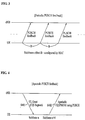
- FIG. 4 is a conceptual diagram illustrating a method for allowing the user equipment (UE) to aperiodically transmit channel state information over a PUSCH according to the present invention.
- the user equipment is able to receive an indicator (indicator of 1 bit or N bits) requesting aperiodic transmission of channel state information from a base station over a downlink control channel at step S401.
- the indicator received at the step S401 may be used as an UL Grant signal.
- this indicator may hereinafter be referred to as a CQI Request having a length of 1 bit.
- the CQI Request may have more bits to indicate whether subband channel state information is requested, as well as to inform the UE of additional information such as a subband position.
- the user equipment (UE) having received the CQI Request signal as described above answers the CQI Request signal after the lapse of a predetermined time, such that it is able to transfer aperiodic channel state information such as CQI/ PMI/RI over a PUSCH at step S402.
- the UE receives the CQI Request at the N-th subframe, it is able to transmit CQI/PMI/RI over the PUSCH to answer the CQI Request at the (n+4)-th subframe.
- the PUSCH may further include a CRC for detecting errors of a Tx signal, such that the resultant PUSCH may be transferred.
- the base station having received aperiodic channel state information determines the presence or absence of errors in channel state information received from the user equipment (UE), such that the determined result may be notified as confirmation information to the user equipment (UE).
- the CRC may be attached to channel state information of some categories according to a control information multiplexing scheme, an amount of information, and a requested reliability, such that the CRC-attached channel state information may be transferred.
- confirmation information indicating that the latest PMI reported from the UE to the base station has been used by the base station, may be referred to as PMI confirmation information.
- a wideband PMI decided as either a designated frequency area or a total system band, and a rank information feedback.
- this specific code may be a parity check code (e.g., even/odd parity, Hamming code).
- an error detection capability based on a syndrome check of an algebraic code based coding of the PUCCH can be assigned.
- the error detection capability based on the aforementioned algebraic code based coding may be damaged by length adaptation for a code sequence. Therefore, additional error detection codes may be inserted into the PUCCH, such that it is preferable that the error detection capability is strengthened.
- the number of bits of control information (CQI, PMI, and/or RI) fed back over an arbitrary PUCCH in an arbitrary feedback event is higher than a maximum number of transmittable information bits which satisfy a QoS requested by the PUCCH (i.e., if any redundant bit capable of satisfying a QoS requested on the PUCCH does not exist), the insertion of additional error detection codes or the strengthening of arbitrary error detection capability may have unexpected difficulty.
- control information be fed back with a prescribed margin to prepare for the maximum number of control information bits which satisfy a QoS in all PUCCH transmissions simultaneously while being fed back.
- one embodiment of the present invention provides a method for transferring CQI/PMI information and RI information at different times. Also, if the wideband CQI/PMI and the subband CQI/PMI are simultaneously transmitted, it is preferable that the wideband CQI/PMI and the subband CQI/PMI be transmitted at different times. Transmitting the wideband CQI/PMI, the subband CQI/PMI, and the RI at different times may be designated to have periods of different lengths in view of individual information which is periodically transmitted over the PUCCH, or the above transmitting may have the same period whereas it has different transmission times, in such a way that the aforementioned transmitting may be implemented.
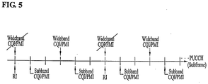
- FIG. 5 is a conceptual diagram illustrating a method for periodically transmitting a wideband CQI/PMI, a subband CQI/PMI, and an RI over a PUCCH according to the present invention.
- the wideband CQI/PMI and the RI must be transferred at different times according to this embodiment of the present invention.
- the wideband CQI/PMI and the subband CQI/PMI are transferred via different subframes contained in the PUCCH.
- the RI is transmitted with a period longer than a period corresponding to the subframe of 3n. If the RI also needs to be transmitted at a transmission time of the wideband CQI/PMI, it is assumed that the RI having a longer period is transmitted.
- the wideband CQI/PMI, the subband CQI/PMI, and the RI are simultaneously transmitted.
- the subband CQI/PMI is transmitted at a specific time between two successive wideband CQI/PMI transmission times, and it is assumed that each transmission is periodically carried out.
- the CQI/PMI and RI, the wideband CQI/PMI, and the subband CQI/PMI and RI are transmitted via different subframes of the PUCCH, such that a capacity space capable of increasing the error detection throughput can be easily detected from the PUCCH.
- this embodiment may configure a coding process using a specific pattern for enhancing the error detection capability in case of a permutation for a length matching or a puncturing process.
- an additional coding for each information may be carried out and this coded result may be then joint-coded, resulting in the implementation of a total coding process.
- the present invention is not limited to only the above-mentioned embodiments, but can be applied to other examples which can satisfy the above principles and new characteristics of the present invention.
- the present invention can be applied to a variety of wireless communication systems.
- the above-mentioned embodiments can be readily applied to a 3GPP LTE system and a 3GPP LTE-A system acting as a new version of the 3GPP LTE system, and the scope or spirit of the present invention is not limited to only the 3GPP LTE system and the 3GPP LTE-A system but can also be applied to a variety of wireless communication systems which allow the user equipment (UE) to periodically or aperiodically transmit channel state information to the base station.
- UE user equipment
Landscapes
- Engineering & Computer Science (AREA)
- Computer Networks & Wireless Communication (AREA)
- Signal Processing (AREA)
- Physics & Mathematics (AREA)
- Mathematical Physics (AREA)
- Mobile Radio Communication Systems (AREA)
- Radio Transmission System (AREA)
Description
- The present invention relates to a method for enabling a terminal to periodically and/ or aperiodically report channel state information to a base station, and a method for enabling the base station to receive the channel state information, wherein it is assumed that the channel state information for use in a multi-antenna system (i.e., a Multiple-Input Multiple-Output (MIMO) system) includes a channel quality indicator (CQI), a precoding matrix index (PMI), and a rank indicator (RI).
- Generally, a multi-antenna technology (hereinafter referred to as an MIMO technology) will hereinafter be described in detail.
- In brief, the MIMO technology is an abbreviation of the Multi-Input Multi-Output technology. The MIMO technology uses multiple transmission (Tx) antennas and multiple reception (Rx) antennas to improve the efficiency of transmission/reception (Tx/Rx) data, whereas a conventional art has generally used a single transmission (Tx) antenna and a single reception (Rx) antenna. In more detail, the MIMO technology is not dependent on a single antenna path to receive a single entire message, and completes the entire message by collecting a plurality of data fragments received via several antennas. As a result, the MIMO technology can increase a data transfer rate within a specific range, or can increase a system range at a specific data transfer rate.
-
FIG. 1 is a block diagram illustrating a conventional MIMO system. - If the number of antennas of a reception end and the number of antennas of a reception end are simultaneously increased as shown in
FIG. 1 , theoretical channel transmission capacity increases in proportion to the number of antennas in a different way from a conventional art in which only a transmitter or a receiver uses multiple antennas, such that a frequency efficiency can be greatly improved. - The MIMO technology can be classified into a spatial diversity scheme and a spatial multiplexing scheme. The spatial diversity scheme increases transmission reliability using symbols passing various channel paths. The spatial multiplexing scheme simultaneously transmits a plurality of data symbols via a plurality of Tx antennas, so that it increases a transfer rate of data. In addition, the combination of the spatial diversity scheme and the spatial multiplexing scheme has also been recently researched to properly acquire unique advantages of the two schemes.
- Detailed descriptions of the spatial diversity scheme, the spatial multiplexing scheme, and the combination thereof will hereinafter be described in detail.
- Firstly, the spatial diversity scheme will hereinafter be described. The spatial diversity scheme is classified into a space-time block code scheme and a space-time Trellis code scheme which simultaneously uses a diversity gain and a coding gain. Generally, a bit error ratio (BER) improvement performance and a code-generation degree of freedom of the space-time Trellis code scheme are superior to those of the space-time block code scheme, whereas the calculation complexity of the space-time block code scheme is superior to that of the space-time Trellis code scheme. A spatial diversity gain corresponds to the product or multiplication of the number of Tx antennas and the number of Rx antennas. In the meantime, if a space-time coding scheme is applied to a frequency domain instead of a time domain, this space-time coding scheme may also be considered to be a frequency-space coding scheme, and a coding scheme applied to this frequency-space coding scheme is equal to that of the space-time coding scheme.
- Secondly, the spatial multiplexing scheme will hereinafter be described. The spatial multiplexing scheme is adapted to transmit different data streams via individual Tx antennas. In this case, a receiver may unavoidably generate mutual interference between data fragments which have been simultaneously transmitted from a transmitter. The receiver removes this mutual interference using a proper signal processing technique, so that it can receive the resultant data having no interference. In order to remove noise from the received data, a maximum likelihood receiver, a ZF receiver, a MMSE receiver, a D-BLAST, or a V-BLAST may be used. Specifically, if a transmission end is able to recognize channel information, a Singular Value Decomposition (SVD) scheme may be used to remove the noise.
- Thirdly, the combination of the spatial diversity scheme and the spatial multiplexing scheme will hereinafter be described. Provided that only a spatial diversity gain is acquired, a performance-improvement gain is gradually saturated in proportion to an increasing diversity order. Otherwise, provided that only the spatial multiplexing gain is acquired, a transmission reliability of a radio frequency (RF) channel is gradually deteriorated. As a result, a variety of schemes capable of acquiring both the aforementioned two gains simultaneously while solving the above-mentioned problems have been intensively researched by many companies or developers, for example, a double-STTD scheme and a space-time BICM (STBICM) scheme.
- In the meantime, a general communication system performs coding of transmission information of a transmission end using a forward error correction code, and transmits the coded information, so that channel errors can be corrected by a reception end. The reception end demodulates a received (Rx) signal, performs decoding of forward error correction code, and recovers transmission information. By the decoding process, errors of the Rx signal caused by the channel can be corrected.
- Each of all forward error correction codes has a maximum-correctable limitation in a channel error correction. In other words, if a reception (Rx) signal has an error exceeding the limitation of a corresponding forward error correction code, a reception end is unable to decode the Rx signal into information having no error. Therefore, there is a need for the reception end to determine the presence or absence of an error in the decoded information. In this way, a specialized coding process for performing error detection is required, separately from the forward error correction coding process. Generally, a Cyclic Redundancy Check (CRC) code has been used as an error detection code.
- The CRC method is an exemplary coding method for performing the error detection instead of the error correction. Generally, transmission information is coded by the CRC method, and then the forward error correction code is applied to the CRC-coded information. A single unit coded by the CRC and the forward error correction code is generally called a codeword. Respective codewords are mapped to streams corresponding to ranks, and the mapped result is transmitted, where the number of streams is equal to the number of ranks corresponding to independent channels of a MIMO communication system.
- Meanwhile, in the above-mentioned MIMO system, a transmission end performs precoding of Tx data, and transmits the precoded Tx data, and a reception end receives signals using a precoding vector used by the transmission end.
- The precoding vector for performing the above precoding is set to any one of precoding vectors which have been predefined as a codebook format in transmission/ reception ends. In this case, a transmission scheme of the transmission end can be classified into an open-loop transmission method and a closed-loop transmission method according to specific information indicating whether or not the precoding vector of the transmission end requests feedback information from the reception end.
- In case of the open-loop transmission method, the transmission end selects a precoding vector without using feedback information of the reception end, and transmits signals. Otherwise, in case of the closed-loop transmission method, the reception end indicates a specific precoding vector among predefined codebooks according to a reception end, and feeds back channel information associated with the specific precoding vector, such that the transmission end transmits signals using such a feedback signal.
- In the meantime, in order to implement effective communication, there is a need for channel information to be notified along a feedback path, downlink channel information is uploaded to an uplink, and uplink channel information is downloaded to a downlink. The downlink or uplink channel information is represented by a channel information indicator (CQI), i.e., a channel quality indicator (CQI). This CQI can be generated by various methods. For example, a method for quantizing channel state information without any change and uploading the quantized channel state information, a method for calculating an SINR and uploading the calculated SINR, and a method for notifying a channel s actual application state as in a modulation coding scheme (MCS) can be used.
- In this MIMO system, channel state information (CSI) to be notified to a base station by a terminal may include the above CQI, the precoding matrix index (PMI), and the rank indicator (RI) indicating the number of independent channels. This channel state information is periodically notified to a base station over a Physical Uplink Control Channel (PUCCH) and/or a Physical Uplink Shared Channel (PUSCH).
The 3GPP Draft No. R1-074854, entitled "Channel feedback format selection", discloses principles for determining how a UE should be instructed to select the channel feedback format, and how the transmission format may be selected.
The 3GPP Draft No. R1-074289, entitled "On CQI Reporting in E-UTRA", discusses issues on the usage of CQI reports in the PUCCH and PUSCH, and a configuration method of PUCCH and PUSCH for CQI reporting.
The 3GPP Draft No. R1-074660, entitled "Consideration of CQI, PMI, and rank report feedback interval", discloses CQI, PMI, and rank report feedback interval.
The 3GPP Draft No. R1-074853, entitled "Frequency-selective CQI Report Formats", discloses frequency-selective CQI report formats. - Accordingly, the present invention is directed to a method for transmitting and receiving channel state information periodically or aperiodically, that substantially obviates one or more problems due to limitations and disadvantages of the related art.
- There are needed a method for allowing a terminal to periodically transmit channel state information to a base station, and a method for allowing the terminal to aperiodically transmit the channel state information to the base station upon receiving a request from the base station.
- In order to solve the above-mentioned problems, an object of the present invention is to provide a method for allowing the terminal to effectively transmit channel state information aperiodically.
- Also, if the channel state information is periodically transmitted, an error detection capability is insufficient for current PUCCH transmission, such that a space for inserting an error detection code used to supplement the insufficient error detection capability may encounter unexpected problems.
- In order to solve the above-mentioned problems, another object of the present invention is to provide a method for effectively solving PUCCH channel capacity problems while the terminal periodically transmits channel state information.
- Additional advantages, objects, and features of the invention will be set forth in part in the description which follows and in part will become apparent to those having ordinary skill in the art upon examination of the following or may be learned from practice of the invention. The objectives and other advantages of the invention may be realized and attained by the structure particularly pointed out in the written description
and claims hereof as well as the appended drawings. - To achieve these objects and other advantages and in accordance with the purpose of the invention, as embodied and broadly described herein, a method for transmitting channel state information (CSI) by a terminal is provided as set forth in the appended claims.
- In another aspect of the present invention, there is provided a terminal as set forth in the appended claims.
- The present invention may provide a method for allowing a terminal to aperiodically transmit channel state information to a base station upon receiving a request from the base station. In more detail, the base station prescribes an indicator for transmitting aperiodic channel state information to the terminal in a downlink control channel, such that aperiodic channel state information can be effectively transmitted. Transmission over a PUSCH is prescribed, such that the error detection capability of the base station can be guaranteed.
- Also, the present invention transmits various channel state information transmitted over a PUCCH, for example, a wideband PMI/CQI, a subband PMI/CQI, and an RI at different times, resulting in a guarantee of PUCCH capacity.
- It is to be understood that both the foregoing general description and the following detailed description of the present invention are exemplary and explanatory and are intended to provide further explanation of the invention as claimed.
- The accompanying drawings, which are included to provide a further understanding of the invention and are incorporated in and constitute a part of this application, illustrate embodiment(s) of the invention and together with the description serve to explain the principle of the invention. In the drawings:
-
FIG. 1 is a block diagram illustrating a conventional MIMO system; -
FIGS. 2 and3 illustrate methods for allowing a terminal to periodically transmitt channel state information to a base station; -
FIG. 4 is a conceptual diagram illustrating a method for allowing a terminal to aperiodically transmit channel state information over a PUSCH according to the present invention; and -
FIG. 5 is a conceptual diagram illustrating a method for periodically transmitting a wideband CQI/PMI, a subband CQI/PMI, and an RI over a PUCCH according to the present invention. - Reference will now be made in detail to the preferred embodiments of the present invention, examples of which are illustrated in the accompanying drawings. Wherever possible, the same reference numbers will be used throughout the drawings to refer to the same or like parts. The following embodiments of the present invention may be modified into various formats, and the scope of the present invention is not limited to only the following embodiments and can also be applied to other examples.
- For the convenience of description and better understanding of the present invention, the following detailed description will disclose a variety of embodiments and modifications of the present invention. However, those skilled in the art will readily understand and implement the embodiments and modifications of the present invention. In some cases, in order to prevent ambiguous concepts of the present invention from occurring, conventional devices or apparatus well known to those skilled in the art will be omitted and be denoted in the form of a block diagram on the basis of the important functions of the present invention. Wherever possible, the same reference numbers will be used throughout the drawings to refer to the same or like parts.
- In the following description, a terminal may include a user equipment (UE), a mobile terminal (Mobile Terminal), and a mobile station (MS), and may also be called any one of them as necessary. Also, the base station may include a Node-B and an eNode-B, and may also be called either of them.
- One embodiment of the present invention provides a method for allowing a terminal to effectively transmit channel state information aperiodically. Presently, channel state information including a CQI, a PMI and an RI may be periodically transferred from the terminal to the base station over the PUCCH.
-
FIGS. 2 and3 illustrate methods for allowing a terminal to periodically transmitt channel state information to a base station. - Referring to
FIGS. 2 and3 , a user equipment (UE) transmits a CQI, a PMI and an RI over a PUCCH and/or a PUSCH at intervals of a predetermined period, such that the UE need not receive a special grant signal for transmitting channel state information from the base station. The user equipment (UE) feeds back channel state information (CQI, PMI, and RI) over a PUCCH or PUSCH at intervals of a specific period (e.g., A frame under PUCCH transmission or a B frame under PUSCH transmission) constructed by an upper layer (e.g., an RRC layer). - Generally, due to the limitation of given capacity, the PUCCH signal is transmitted under the condition that there is no additional error detection code such as a CRC. Also, channel state information is transferred over a PUSCH due to the limitation of PUCCH capacity. In case of the PUSCH, this channel state information includes an error detection code such as a CRC, such that the resultant channel state information is transmitted over the PUSCH.
- However, in some cases, there is needed a specific procedure for a base station to report channel state information to a user equipment (UE) at a specific time, separately from another procedure for allowing the base station to periodically report the channel state information. If a channel state information transmission event (i.e., eNB triggered CSI reporting event) induced by the base station occurs, there is a need for the base station to inform the user equipment (UE) of the eNB triggered CSI reporting event over a downlink control channel by an indicator. Therefore, scheduling information for an uplink channel can be carried out, and it is more preferable for an uplink grant (UL Grant) signal for a PUSCH to be carried out as described above. There is no need for the above-mentioned indicator to have a long length, such that an uplink channel information transmission request such as a CQI report request may be transferred to the user equipment (UE) by a signaling process of one bit. In case of applying an aperiodic channel state report scheme to a PUSCH-based channel state report scheme except for a PUCCH-based periodic channel state information report scheme in a method for reporting channel state information such as a CQI, a PMI, or an RI, in order to add an indication function of at least one channel state information requested from among several channel state information including the above three channel state information, a signaling process of N bits (where N 2) instead of one bit may be contained in an uplink acknowledgement (ACK) signal for the PUSCH.
- In the meantime, an error detection capability of the PUCCH may be less than that of the PUSCH as described above. Therefore, channel state information aperiodically reported by the user equipment (UE) may be transferred over the PUSCH capable of detecting CRC errors. As a result, the base station is able to detect Rx errors of the CQI, PMI, and RI, and is able to aperiodically acquire channel state information.
- Channel state information transferred by the user equipment (UE) may be either wideband channel state information of all system bands or subband channel state information of an arbitrary frequency band contained in an overall system band. In case of transferring the subband channel state information (e.g., subband PMI), each subband PMI may be cyclically transferred in an overall system band, or may also be transferred over an upper layer according to a predetermined order.
-
FIG. 4 is a conceptual diagram illustrating a method for allowing the user equipment (UE) to aperiodically transmit channel state information over a PUSCH according to the present invention. - Referring to
FIG. 4 , the user equipment (UE) is able to receive an indicator (indicator of 1 bit or N bits) requesting aperiodic transmission of channel state information from a base station over a downlink control channel at step S401. The indicator received at the step S401 may be used as an UL Grant signal. For the convenience of description, this indicator may hereinafter be referred to as a CQI Request having a length of 1 bit. However, the CQI Request may have more bits to indicate whether subband channel state information is requested, as well as to inform the UE of additional information such as a subband position. - In the meantime, the user equipment (UE) having received the CQI Request signal as described above answers the CQI Request signal after the lapse of a predetermined time, such that it is able to transfer aperiodic channel state information such as CQI/ PMI/RI over a PUSCH at step S402. Preferably, if the UE receives the CQI Request at the N-th subframe, it is able to transmit CQI/PMI/RI over the PUSCH to answer the CQI Request at the (n+4)-th subframe.
- PUSCH may further include a CRC for detecting errors of a Tx signal, such that the resultant PUSCH may be transferred. So, the base station having received aperiodic channel state information determines the presence or absence of errors in channel state information received from the user equipment (UE), such that the determined result may be notified as confirmation information to the user equipment (UE). In this case, in association with all categories of channel state information transferred over the PUSCH, the CRC may be attached to channel state information of some categories according to a control information multiplexing scheme, an amount of information, and a requested reliability, such that the CRC-attached channel state information may be transferred. Specifically, confirmation information, indicating that the latest PMI reported from the UE to the base station has been used by the base station, may be referred to as PMI confirmation information.
- In the meantime, in case of using PMI confirmation information in a downlink control channel, it is very important for the base station to detect errors in a subband PMI, a wideband PMI decided as either a designated frequency area or a total system band, and a rank information feedback.
- Therefore, if the number of bits of control information (CQI, PMI, and/or RI) fed back over an arbitrary PUCCH is less than a maximum number of transmittable information bits which satisfy a QoS requested by the PUCCH in an arbitrary feedback event (i.e., if there is a redundant space in transmission bits capable of satisfying a QoS designated on the PUCCH without using an additional addition process), it is preferable for a specific code for strengthening an error detection capability to be inserted into the PUCCH. For example, this specific code may be a parity check code (e.g., even/odd parity, Hamming code). By this parity check code, an error detection capability based on a syndrome check of an algebraic code based coding of the PUCCH can be assigned. But, the error detection capability based on the aforementioned algebraic code based coding may be damaged by length adaptation for a code sequence. Therefore, additional error detection codes may be inserted into the PUCCH, such that it is preferable that the error detection capability is strengthened.
- If the number of bits of control information (CQI, PMI, and/or RI) fed back over an arbitrary PUCCH in an arbitrary feedback event is higher than a maximum number of transmittable information bits which satisfy a QoS requested by the PUCCH (i.e., if any redundant bit capable of satisfying a QoS requested on the PUCCH does not exist), the insertion of additional error detection codes or the strengthening of arbitrary error detection capability may have unexpected difficulty.
- Therefore, in order to always provide the error detection capability of a PUCCH control information feedback, it is preferable that the control information be fed back with a prescribed margin to prepare for the maximum number of control information bits which satisfy a QoS in all PUCCH transmissions simultaneously while being fed back.
- Therefore, if channel state information is periodically transferred over the PUCCH, one embodiment of the present invention provides a method for transferring CQI/PMI information and RI information at different times. Also, if the wideband CQI/PMI and the subband CQI/PMI are simultaneously transmitted, it is preferable that the wideband CQI/PMI and the subband CQI/PMI be transmitted at different times. Transmitting the wideband CQI/PMI, the subband CQI/PMI, and the RI at different times may be designated to have periods of different lengths in view of individual information which is periodically transmitted over the PUCCH, or the above transmitting may have the same period whereas it has different transmission times, in such a way that the aforementioned transmitting may be implemented.
-
FIG. 5 is a conceptual diagram illustrating a method for periodically transmitting a wideband CQI/PMI, a subband CQI/PMI, and an RI over a PUCCH according to the present invention. - Referring to
FIG. 5 , if the wideband CQI/PMI and the RI are simultaneously transmitted, the wideband CQI/PMI and the RI must be transferred at different times according to this embodiment of the present invention. As can be seen fromFIG. 5 , it is assumed that the wideband CQI/PMI and the subband CQI/PMI are transferred via different subframes contained in the PUCCH. For example, if the wideband CQI/PMI is transmitted at intervals of a 3n subframe, it is preferable that the RI is transmitted with a period longer than a period corresponding to the subframe of 3n. If the RI also needs to be transmitted at a transmission time of the wideband CQI/PMI, it is assumed that the RI having a longer period is transmitted. - Also, it is assumed that the wideband CQI/PMI, the subband CQI/PMI, and the RI are simultaneously transmitted. As can be seen from
FIG. 5 , the subband CQI/PMI is transmitted at a specific time between two successive wideband CQI/PMI transmission times, and it is assumed that each transmission is periodically carried out. - It should be noted that the timing relationship in periodic transmission among the wideband CQI/PMI, the subband CQI/PMI, and the RI has been disclosed for only illustrative purposes, and a detailed timing relationship of them may be designed according to different requirements of a system.
- As shown in the above-mentioned embodiment, the CQI/PMI and RI, the wideband CQI/PMI, and the subband CQI/PMI and RI are transmitted via different subframes of the PUCCH, such that a capacity space capable of increasing the error detection throughput can be easily detected from the PUCCH.
- In the meantime, in order to simultaneously provide an error detection capability and a length adaptation capability of a code sequence during an algebraic code based coding process when the CQI/PMI and the RI are transmitted according to another embodiment, this embodiment may configure a coding process using a specific pattern for enhancing the error detection capability in case of a permutation for a length matching or a puncturing process.
- Also, if there are different QoS requirements (i.e., requirements to prepare for errors) in heterogeneous control information, or if there is needed to increase the probability of detecting individual control information (e.g., there is needed to increase the probability of recovering one of two information when an error has occurred), an additional coding for each information may be carried out and this coded result may be then joint-coded, resulting in the implementation of a total coding process.
- Although the present invention has been disclosed by referring to the above-mentioned embodiments, it should be noted that the aforementioned embodiments have been disclosed for only illustrative purposes, and those skilled in the art will appreciate that various modifications, additions and substitutions are possible, without departing from the scope of the invention as disclosed in the accompanying claims. Thus, it is intended that the present invention covers the modifications and variations of this invention provided they come within the scope of the appended claims.
- Therefore, the present invention is not limited to only the above-mentioned embodiments, but can be applied to other examples which can satisfy the above principles and new characteristics of the present invention.
- As apparent from the above description, the present invention can be applied to a variety of wireless communication systems. Specifically, the above-mentioned embodiments can be readily applied to a 3GPP LTE system and a 3GPP LTE-A system acting as a new version of the 3GPP LTE system, and the scope or spirit of the present invention is not limited to only the 3GPP LTE system and the 3GPP LTE-A system but can also be applied to a variety of wireless communication systems which allow the user equipment (UE) to periodically or aperiodically transmit channel state information to the base station.
Claims (7)
- A method for transmitting channel state information, CSI, by a terminal, the method comprising:receiving an indicator requesting a channel state information report of a downlink channel from a base station over a downlink control channel;aperiodically transmitting the CSI to the base station over a physical uplink shared channel, PUSCH, upon receiving the indicator from the base station; andperiodically transmitting the CSI to the base station over a physical uplink control channel, PUCCH,wherein the CSI includes a wideband precoding matrix index, PMI, and a subband PMI,the method being characterized in that periodically transmitting the CSI to the base station over the PUCCH comprises:determining a transmission time for transmitting a channel quality indicator, CQI, or a precoding matrix index, PMI, over the PUCCH to the base station, wherein the CQI includes a wideband CQI and a subband CQI, in which the wideband CQI or wideband PMI and the subband CQI or subband PMI are transferred over the PUCCH at different times; anddetermining a transmission time for transmitting a rank indicator, RI, over the PUCCH to the base station,wherein, when the transmission time for transmitting the RI is the same as the transmission time for transmitting the wideband CQI or the wideband PMI, only the RI is transmitted over the PUCCH.
- The method according to claim 1, wherein a cyclic redundancy code, CRC, is attached to a transmission control signal including the CSI transmitted on the PUSCH.
- The method according to claim 1, wherein the PUCCH has an error detection capability weaker than that of the PUSCH.
- The method according to claim 1, further comprising: upon receiving the indicator requesting the channel state information report at a specific sub frame, transmitting the CSI over the PUSCH after a lapse of 4 subframes from the specific subframe.
- The method according to claim 1, wherein if the subband precoding matrix index is transferred, a precoding matrix index for each subband is cyclically transmitted in an entire system band or is transferred from an upper layer higher than a physical layer according to a predetermined order.
- The method according to claim 1, wherein the subband channel quality information is transferred at a specific time between transmission times of two successive wideband channel quality information parts.
- A terminal configured to carry out a method according to any one of claims 1 to 6.
Applications Claiming Priority (3)
| Application Number | Priority Date | Filing Date | Title |
|---|---|---|---|
| US1984308P | 2008-01-08 | 2008-01-08 | |
| KR1020080135367A KR101476202B1 (en) | 2008-01-08 | 2008-12-29 | Method for transmitting / receiving periodic / aperiodic channel status information |
| PCT/KR2009/000084 WO2009088225A2 (en) | 2008-01-08 | 2009-01-08 | Method for transmitting and receiving channel state information periodically or aperiodically |
Publications (3)
| Publication Number | Publication Date |
|---|---|
| EP2215744A2 EP2215744A2 (en) | 2010-08-11 |
| EP2215744A4 EP2215744A4 (en) | 2015-05-13 |
| EP2215744B1 true EP2215744B1 (en) | 2017-10-18 |
Family
ID=41395574
Family Applications (1)
| Application Number | Title | Priority Date | Filing Date |
|---|---|---|---|
| EP09701460.9A Active EP2215744B1 (en) | 2008-01-08 | 2009-01-08 | Method for transmitting and receiving channel state information periodically or aperiodically |
Country Status (6)
| Country | Link |
|---|---|
| US (1) | US8358585B2 (en) |
| EP (1) | EP2215744B1 (en) |
| JP (1) | JP5174923B2 (en) |
| KR (1) | KR101476202B1 (en) |
| CN (1) | CN101911523B (en) |
| WO (1) | WO2009088225A2 (en) |
Families Citing this family (129)
| Publication number | Priority date | Publication date | Assignee | Title |
|---|---|---|---|---|
| DE602008017325C5 (en) | 2007-06-08 | 2022-05-12 | MiiCs & Partners Japan Co., Ltd. | Mobile communication system, base station device and mobile station device |
| DK2141846T3 (en) | 2007-09-06 | 2013-03-11 | Sharp Kk | Communication apparatus and method of communication |
| JP4652420B2 (en) * | 2008-01-08 | 2011-03-16 | 株式会社エヌ・ティ・ティ・ドコモ | User apparatus, transmission method, and mobile communication system |
| PT3352407T (en) | 2008-03-31 | 2019-10-28 | Ericsson Telefon Ab L M | Methods and arrangements in a telecommunications system |
| US20110134782A1 (en) * | 2008-06-23 | 2011-06-09 | Sharp Kabushiki Kaisha | Mobile station apparatus, communication system and communication method |
| US8750251B2 (en) * | 2008-08-15 | 2014-06-10 | Sung-Hyuk Shin | Method and apparatus for implementing network coding in a long term evolution advanced system |
| KR101430981B1 (en) * | 2008-10-13 | 2014-08-18 | 삼성전자주식회사 | Apparatus and method for transmitting dynamic channel information in a MIMO system |
| US8200165B2 (en) * | 2009-06-26 | 2012-06-12 | Hongmei Sun | Techniques for transmission of channel quality data in wireless systems |
| KR20100075378A (en) | 2008-12-24 | 2010-07-02 | 엘지전자 주식회사 | Method and appratus of transmitting control information |
| US8560696B2 (en) | 2009-04-28 | 2013-10-15 | Intel Corporation | Transmission of advanced-MAP information elements in mobile networks |
| US9491648B2 (en) | 2009-07-21 | 2016-11-08 | Lg Electronics Inc. | Apparatus and method for transmitting channel state information in a wireless communication system |
| EP2282575A1 (en) * | 2009-08-04 | 2011-02-09 | Panasonic Corporation | Channel quality reporting in a mobile communications system |
| CN101998497B (en) * | 2009-08-19 | 2013-03-27 | 中兴通讯股份有限公司 | Method and device for reporting channel state information aperiodically |
| CN101667864B (en) * | 2009-09-28 | 2012-05-23 | 中兴通讯股份有限公司 | Method, system and device for downlink physical link fault diagnosis |
| WO2011041623A1 (en) | 2009-10-01 | 2011-04-07 | Interdigital Patent Holdings, Inc. | Uplink control data transmission |
| US8565143B2 (en) | 2009-10-16 | 2013-10-22 | At&T Mobility Ii, Llc | Dynamic content distribution in mobile telecommunications network |
| WO2011074923A2 (en) * | 2009-12-17 | 2011-06-23 | 엘지전자 주식회사 | Method and apparatus for transmitting channel status information efficiently in a multi-carrier wireless communication system |
| JP5124597B2 (en) * | 2010-01-08 | 2013-01-23 | 株式会社エヌ・ティ・ティ・ドコモ | User apparatus, base station and method in mobile communication system |
| WO2011082626A1 (en) * | 2010-01-08 | 2011-07-14 | Huawei Technologies Co., Ltd. | Reporting of channel state information |
| EP2522095A2 (en) | 2010-01-08 | 2012-11-14 | InterDigital Patent Holdings, Inc. | Channel state information transmission for multiple carriers |
| CN102130708B (en) * | 2010-01-15 | 2014-04-30 | 华为技术有限公司 | Method for feeding back multicell channel state information and user equipment |
| US8644422B2 (en) * | 2010-02-12 | 2014-02-04 | Blackberry Limited | Low overhead PMI and CQI feedback and pairing schemes for MU-MIMO |
| JP2013524561A (en) * | 2010-03-25 | 2013-06-17 | ノキア シーメンス ネットワークス オサケユキチュア | Channel information signaling |
| US8520491B2 (en) | 2010-04-01 | 2013-08-27 | Nokia Siemens Networks Oy | Periodic channel state information signaling with carrier aggregation |
| KR101871707B1 (en) * | 2010-04-02 | 2018-06-27 | 엘지전자 주식회사 | User equipment apparatus and method for feedback channel state information in wireless communication system |
| EP2556712B1 (en) * | 2010-04-05 | 2020-09-09 | Nokia Technologies Oy | Channel state information feedback for enhanced downlink multiple input - multiple output operation |
| CN102215591B (en) * | 2010-04-06 | 2013-12-04 | 华为技术有限公司 | A transmission method of channel state information, user equipment and base station |
| CN103648176B (en) * | 2010-04-06 | 2018-07-03 | 华为技术有限公司 | The transmission method and user equipment of a kind of channel state information and base station |
| US8923233B2 (en) * | 2010-04-12 | 2014-12-30 | Lg Electronics Inc. | Method and device for efficient feedback in wireless communication system supporting multiple antennas |
| CN101867447B (en) * | 2010-04-30 | 2015-09-16 | 中兴通讯股份有限公司 | The feedback method of channel condition information and terminal |
| CN101834708B (en) * | 2010-04-30 | 2015-01-28 | 中兴通讯股份有限公司 | Method and device for acquiring channel information |
| JP5276047B2 (en) * | 2010-04-30 | 2013-08-28 | 株式会社エヌ・ティ・ティ・ドコモ | Mobile terminal device |
| US8422429B2 (en) | 2010-05-04 | 2013-04-16 | Samsung Electronics Co., Ltd. | Method and system for indicating the transmission mode for uplink control information |
| CN102237955B (en) * | 2010-05-07 | 2013-11-06 | 电信科学技术研究院 | Channel state information reporting method and device |
| CN102237958B (en) * | 2010-05-07 | 2013-10-16 | 电信科学技术研究院 | Method and device for reporting CSI (Channel State Information) based on PUCCH (Physical Uplink Control Channel) |
| CN102244566B (en) * | 2010-05-11 | 2014-03-12 | 中兴通讯股份有限公司 | Downlink transmission method and base station for multiple input and multiple output (MIMO) system |
| US8599761B2 (en) * | 2010-05-14 | 2013-12-03 | Samsung Electronics Co., Ltd. | Systems and methods for PUCCH feedback in 3GPP wireless networks |
| US9054852B2 (en) | 2010-06-08 | 2015-06-09 | Lg Electronics Inc. | Method and device for transmitting/receiving channel state information in coordinated multipoint communication system |
| WO2011155777A2 (en) * | 2010-06-09 | 2011-12-15 | 엘지전자 주식회사 | Method and device for transmitting/receiving channel state information in wireless communication system supporting multicarriers |
| JP5324526B2 (en) * | 2010-06-18 | 2013-10-23 | シャープ株式会社 | Terminal apparatus, base station apparatus, communication system, and processing method |
| US8929309B2 (en) * | 2010-06-18 | 2015-01-06 | Interdigital Patent Holdings, Inc. | Long-term feedback transmission and rank reporting |
| CN101877627B (en) * | 2010-06-21 | 2015-09-16 | 中兴通讯股份有限公司 | The feedback method of channel condition information and terminal |
| JP2013531431A (en) | 2010-06-21 | 2013-08-01 | 富士通株式会社 | Channel state information feedback method and equipment for use in wireless communication system |
| CN107181569B (en) * | 2010-06-21 | 2020-07-31 | 富士通株式会社 | Wireless communication system and wireless communication device |
| CN102291218B (en) * | 2010-06-21 | 2016-06-15 | 夏普株式会社 | Channel state information feedback resource distribution method and channel state information feedback method |
| CN102332962B (en) | 2010-07-08 | 2013-12-18 | 华为技术有限公司 | Channel state information reporting and acquiring method, base station and user equipment |
| JP5668139B2 (en) * | 2010-07-26 | 2015-02-12 | エルジー エレクトロニクス インコーポレイティド | Aperiodic channel state information feedback method in wireless access system supporting multi-carrier aggregation |
| US9337954B2 (en) | 2010-07-28 | 2016-05-10 | Qualcomm Incorporated | Protocol for channel state information feedback |
| CN102377530B (en) * | 2010-08-16 | 2014-07-23 | 电信科学技术研究院 | Method, device and system for feeding back channel state information |
| JP5357119B2 (en) * | 2010-08-16 | 2013-12-04 | 株式会社エヌ・ティ・ティ・ドコモ | Mobile terminal device and wireless communication method |
| CN102013953B (en) * | 2010-08-16 | 2014-11-05 | 中兴通讯股份有限公司 | Method for sending channel information, terminal, base station and LTE-A system |
| KR101806878B1 (en) * | 2010-08-16 | 2018-01-10 | 삼성전자주식회사 | Codebook for 8 transmission antennas and multiple input multiple output communication system of the codebook |
| US9100169B2 (en) | 2010-09-15 | 2015-08-04 | Futurewei Technologies, Inc. | System and method for channel state information feedback in wireless communications systems |
| KR20120029338A (en) | 2010-09-16 | 2012-03-26 | 엘지전자 주식회사 | Method and apparatus for efficient feedback in a wireless communication system supporting multiple antenna |
| CN101944985B (en) * | 2010-09-20 | 2015-03-25 | 中兴通讯股份有限公司 | Feedback method for channel state information |
| CN102412941B (en) * | 2010-09-21 | 2014-04-02 | 华为技术有限公司 | Methods for transmission configuration and transmission of periodic channel state information, and apparatuses |
| KR101835326B1 (en) | 2010-09-26 | 2018-03-07 | 엘지전자 주식회사 | Method and apparatus for efficient feedback in a wireless communication system supporting multiple antenna |
| US9602177B2 (en) | 2010-09-26 | 2017-03-21 | Lg Electronics Inc. | Method and apparatus for efficient feedback in a wireless communication system supporting multiple antennas |
| KR101901927B1 (en) | 2010-09-28 | 2018-09-27 | 엘지전자 주식회사 | Inter-cell interference coordination in a wireless communication system |
| US8687555B2 (en) | 2010-09-29 | 2014-04-01 | Lg Electronics Inc. | Method and apparatus for performing effective feedback in wireless communication system supporting multiple antennas |
| KR20120033249A (en) | 2010-09-29 | 2012-04-06 | 엘지전자 주식회사 | Method and apparatus for efficient feedback in a wireless communication system supporting multiple antenna |
| JP5995850B2 (en) * | 2010-09-29 | 2016-09-21 | エルジー エレクトロニクス インコーポレイティド | Efficient feedback method and apparatus in multi-antenna assisted wireless communication system |
| CN101969361B (en) * | 2010-09-30 | 2015-06-03 | 中兴通讯股份有限公司 | Method and device for transmitting cycle feedback report |
| WO2012050330A2 (en) * | 2010-10-10 | 2012-04-19 | 엘지전자 주식회사 | Method and device for transmitting uplink control information in wireless access system |
| WO2012060550A2 (en) * | 2010-11-02 | 2012-05-10 | 엘지전자 주식회사 | Method and apparatus for efficient feedback in wireless communication system supporting multiple antennas |
| CN102468935B (en) * | 2010-11-04 | 2015-03-25 | 大唐移动通信设备有限公司 | Channel state information feedback and acquisition methods and device thereof |
| US8687727B2 (en) * | 2010-11-05 | 2014-04-01 | Intel Corporation | Coordinated multi-point transmission using interference feedback |
| US8868089B2 (en) | 2010-11-09 | 2014-10-21 | Telefonaktiebolaget L M Ericsson (Publ) | Method and arrangement in a telecommunication system |
| US9107211B2 (en) * | 2010-11-17 | 2015-08-11 | Lg Electronics Inc. | Method and device for aperiodically reporting channel state information in wireless connection system |
| US20120127869A1 (en) * | 2010-11-22 | 2012-05-24 | Sharp Laboratories Of America, Inc. | Multiple channel state information (csi) reporting on the physical uplink shared channel (pusch) with carrier aggregation |
| KR20130113471A (en) | 2010-11-24 | 2013-10-15 | 엘지전자 주식회사 | Method and apparatus for transmitting channel status information in carrier aggregation system |
| JP5255043B2 (en) * | 2010-11-26 | 2013-08-07 | シャープ株式会社 | Terminal apparatus, base station apparatus, communication system, and communication method |
| CN102006624B (en) * | 2010-11-29 | 2015-08-12 | 中兴通讯股份有限公司 | The method of the trigger mode of base station and notice aperiodic channel status information reports thereof |
| US9451598B2 (en) | 2010-12-02 | 2016-09-20 | Lg Electronics Inc. | Method and apparatus for transmitting channel status information in carrier aggregation system |
| WO2012077930A2 (en) * | 2010-12-06 | 2012-06-14 | 엘지전자 주식회사 | Method for reporting channel state information in wireless communication system, and device therefor |
| US9179448B2 (en) | 2010-12-20 | 2015-11-03 | Lg Electronics Inc. | Method for reporting channel state information in wireless communication system and device therefor |
| US8711723B2 (en) * | 2010-12-28 | 2014-04-29 | Motorola Mobility Llc | Subband SNR correction in a frequency selective scheduler |
| CN102594528B (en) * | 2011-01-10 | 2017-07-07 | 夏普株式会社 | The triggering method and equipment of non-periodic channel state information feedback |
| CN102595596B (en) * | 2011-01-10 | 2015-06-17 | 华为技术有限公司 | CSI transmission method and apparatuses |
| CN103329612B (en) * | 2011-01-21 | 2017-05-24 | 富士通株式会社 | Method for reporting channel state information, base station and user equipment |
| CN102625355B (en) * | 2011-01-27 | 2014-08-20 | 华为技术有限公司 | Method, related equipment and system for measuring channel state information |
| JP5462203B2 (en) * | 2011-02-18 | 2014-04-02 | 株式会社Nttドコモ | Aperiodic channel state information notification method, radio base station apparatus, user terminal |
| JP5529055B2 (en) | 2011-02-18 | 2014-06-25 | 株式会社Nttドコモ | Radio base station apparatus, terminal and radio communication method |
| KR20140052948A (en) * | 2011-02-23 | 2014-05-07 | 엘지전자 주식회사 | Method for coding and transmitting uplink control information in a wireless access system |
| US20140010188A1 (en) * | 2011-02-23 | 2014-01-09 | Zte (Usa) Inc | Multiple aperiodic channel state information transmission on pusch |
| WO2012118357A2 (en) * | 2011-03-03 | 2012-09-07 | 엘지전자 주식회사 | Method and device for transmitting control information in wireless communication system |
| KR101785313B1 (en) | 2011-04-12 | 2017-10-17 | 삼성전자주식회사 | Method and apparatus of operating subframe and transmitting channel state information for controlling interference in communication system |
| US9544803B2 (en) * | 2011-04-20 | 2017-01-10 | Lg Electronics Inc. | Method for reporting channel state information in a wireless communication system, and apparatus therefor |
| WO2012148443A1 (en) * | 2011-04-29 | 2012-11-01 | Intel Corporation | System and method of rank adaptation in mimo communication system |
| KR101555117B1 (en) | 2011-05-27 | 2015-09-22 | 엘지전자 주식회사 | Method and apparatus for transmitting channel state information in multi-node system |
| US9008677B2 (en) * | 2011-06-08 | 2015-04-14 | Qualcomm Incorporated | Communication devices for multiple group communications |
| EP3595201B1 (en) | 2011-06-10 | 2021-08-18 | QUALCOMM Incorporated | Method and apparatus for transmitting aperiodic channel state information in wireless communication system |
| WO2012169817A2 (en) * | 2011-06-10 | 2012-12-13 | Lg Electronics Inc. | Method and apparatus for transmitting channel state information in multi-node system |
| EP2735104A4 (en) * | 2011-07-19 | 2014-07-23 | Renesas Mobile Corp | METHOD AND APPARATUS FOR MEASURING AND DELIVERING CHANNEL STATUS INFORMATION (CSI) FOR A SEGMENT CARRIER |
| US9325475B2 (en) | 2011-08-05 | 2016-04-26 | Panasonic Intellectual Property Corporation Of America | Terminal, base station, transmission method and reception method in a heterogeneous network regarding comp control of channel information |
| CN102291213B (en) | 2011-08-15 | 2017-06-16 | 中兴通讯股份有限公司 | A kind of terminal and method for calculating channel quality indication (CQI) information |
| CN102315904B (en) * | 2011-09-05 | 2014-02-19 | 新邮通信设备有限公司 | Method for optimizing physical uplink control channel detection and measurement |
| CN103036655B (en) * | 2011-09-30 | 2018-06-19 | 中兴通讯股份有限公司 | A kind of method and apparatus for realizing CSI feedback |
| CN103095419B (en) * | 2011-10-28 | 2017-09-26 | 中兴通讯股份有限公司 | Feedback configuration method based on Physical Uplink Shared Channel, apparatus and system |
| US9603167B2 (en) | 2011-11-07 | 2017-03-21 | Nokia Solutions And Networks Oy | Feedback messaging |
| US9264120B2 (en) | 2011-11-09 | 2016-02-16 | Telefonaktiebolaget L M Ericsson (Publ) | CSI reporting for a set of CSI-RS resources |
| GB2496451A (en) * | 2011-11-14 | 2013-05-15 | Renesas Mobile Corp | Designating a subframe for channel state information measurement at least a specified number of subframes before a subframe in which it is to be reported |
| JP6158834B2 (en) * | 2012-01-11 | 2017-07-05 | エルジー エレクトロニクス インコーポレイティド | Method and apparatus for transmitting / receiving channel state information in wireless connection system |
| KR20130083655A (en) | 2012-01-13 | 2013-07-23 | 삼성전자주식회사 | Method and apparstus for randomizing signal transmission timing of user equipment in wireless communication system |
| US20150071146A1 (en) * | 2012-02-23 | 2015-03-12 | Broadcom Corporation | Aperiodical Discovery Channel Design for Small RRHS |
| US9973955B2 (en) * | 2012-03-16 | 2018-05-15 | Futurewei Technologies, Inc. | Systems and methods for reference signals and CSI feedback |
| US9345015B2 (en) * | 2012-03-23 | 2016-05-17 | Nokia Technologies Oy | Method and apparatus for re-interpreting channel state information |
| KR20150009566A (en) * | 2012-05-08 | 2015-01-26 | 마벨 월드 트레이드 리미티드 | Method and system for reporting feedback in cooperative multipoint transmission |
| WO2013177758A1 (en) | 2012-05-30 | 2013-12-05 | Telefonaktiebolaget L M Ericsson (Publ) | Methods and network nodes for managing transmission of at least one channel quality report |
| US9788226B2 (en) | 2012-06-05 | 2017-10-10 | Lg Electronics Inc. | Method and apparatus for reporting channel state information |
| CN103516488A (en) * | 2012-06-15 | 2014-01-15 | 电信科学技术研究院 | Channel state information feedback method, terminal and network side device |
| KR101443650B1 (en) | 2012-06-15 | 2014-09-23 | 엘지전자 주식회사 | Method and user equipment for transmitting channel state information, and method and base station for receiving channels state information |
| WO2014000206A1 (en) | 2012-06-28 | 2014-01-03 | 华为技术有限公司 | Method and terminal for handling channel state information |
| WO2014021677A1 (en) * | 2012-08-02 | 2014-02-06 | 엘지전자 주식회사 | Method and apparatus for feeding back channel state information in wireless communication system |
| WO2014039056A1 (en) * | 2012-09-10 | 2014-03-13 | Nokia Siemens Networks Oy | Codebook construction using csi feedback for evolving deployment scenarios |
| KR101988285B1 (en) * | 2012-09-20 | 2019-06-12 | 삼성전자 주식회사 | Method and apparatus for transmitting and receiving channel state information in wireless communication system |
| JP5918680B2 (en) * | 2012-10-03 | 2016-05-18 | 株式会社Nttドコモ | Wireless communication system, base station apparatus, user terminal, and wireless communication method |
| CN108112090B (en) * | 2012-11-02 | 2021-07-16 | 华为技术有限公司 | Method, base station and user equipment for determining channel loss |
| JP6598764B2 (en) * | 2013-04-09 | 2019-10-30 | エルジー エレクトロニクス インコーポレイティド | Method and apparatus for transmitting channel state information in wireless connection system |
| JP5542988B2 (en) * | 2013-04-17 | 2014-07-09 | シャープ株式会社 | Terminal apparatus, base station apparatus, communication system, and communication method |
| US9490947B2 (en) * | 2013-08-16 | 2016-11-08 | Lg Electronics Inc. | Method for reporting downlink channel state and apparatus therefor |
| WO2015035603A1 (en) * | 2013-09-13 | 2015-03-19 | 富士通株式会社 | Uplink control information sending method, user equipment and base station |
| WO2015042870A1 (en) * | 2013-09-27 | 2015-04-02 | Qualcomm Incorporated | Csi reporting for lte-tdd eimta |
| JPWO2015141619A1 (en) * | 2014-03-20 | 2017-04-06 | シャープ株式会社 | Terminal apparatus and base station apparatus |
| HUE049819T2 (en) | 2014-05-22 | 2020-10-28 | Qualcomm Inc | Periodic and aperiodic channel state information (csi) reporting for mimo |
| JP2016076889A (en) * | 2014-10-08 | 2016-05-12 | 日本電気株式会社 | Radio communication system, base station, communication method and program |
| CN105991174B (en) * | 2015-03-04 | 2021-03-09 | 株式会社Ntt都科摩 | Method for optimizing rank of channel matrix, wireless base station and mobile station |
| JP6869351B2 (en) * | 2017-01-09 | 2021-05-12 | テレフオンアクチーボラゲット エルエム エリクソン(パブル) | Systems and methods for reliable dynamic instructions for semi-persistent CSI-RS |
| WO2018218393A1 (en) * | 2017-05-27 | 2018-12-06 | Qualcomm Incorporated | Signaling design for joint uplink data and channel state information feedback |
Family Cites Families (21)
| Publication number | Priority date | Publication date | Assignee | Title |
|---|---|---|---|---|
| EP1509012A2 (en) * | 2003-08-20 | 2005-02-23 | Samsung Electronics Co., Ltd. | Method and apparatus for scheduling uplink packet transmission in a mobile communication system |
| WO2005074312A1 (en) | 2004-02-02 | 2005-08-11 | Electronics And Telecommunications Research Institute | A method for requesting and reporting channel quality information in wireless portable internet system |
| KR100612649B1 (en) * | 2004-02-02 | 2006-08-16 | 한국전자통신연구원 | A method for requesting and reporting channel quality information in wireless portable internet system |
| KR20050110409A (en) * | 2004-05-18 | 2005-11-23 | 삼성전자주식회사 | System and method for transmitting cqi channel in communication system with multiple antennas |
| KR20060046335A (en) * | 2004-06-01 | 2006-05-17 | 삼성전자주식회사 | Apparatus and Method for Feedback of Channel State Information Using Arithmetic Coding |
| CN100550711C (en) | 2004-06-07 | 2009-10-14 | 上海贝尔阿尔卡特股份有限公司 | Self adaptation is adjusted the method and the base station of modulation coding mode and/or transmitting power |
| KR20050119590A (en) * | 2004-06-16 | 2005-12-21 | 삼성전자주식회사 | Apparatus and method for feedback of channel quality information in a communication system using orthogonal frequency division multiplexing scheme |
| KR101073909B1 (en) * | 2005-03-04 | 2011-10-17 | 엘지전자 주식회사 | Method of MIMO mode feedback in broadband wireless access system |
| KR100950644B1 (en) * | 2005-03-04 | 2010-04-01 | 삼성전자주식회사 | Feedback method of multi-user multi-input / output system |
| US7457588B2 (en) * | 2005-08-01 | 2008-11-25 | Motorola, Inc. | Channel quality indicator for time, frequency and spatial channel in terrestrial radio access network |
| KR100829505B1 (en) * | 2006-02-21 | 2008-05-16 | 한국전자통신연구원 | Method of transmtting signal in base station and method of transmitting feedback information in terminal |
| JP4767056B2 (en) | 2006-03-24 | 2011-09-07 | 矢崎総業株式会社 | Protector |
| US8014455B2 (en) | 2006-03-27 | 2011-09-06 | Qualcomm Incorporated | Feedback of differentially encoded channel state information for multiple-input multiple-output (MIMO) and subband scheduling in a wireless communication system |
| US7778599B2 (en) * | 2006-05-01 | 2010-08-17 | Intel Corporation | Aggregated channel feedback |
| US20080080635A1 (en) * | 2006-10-02 | 2008-04-03 | Nokia Corporation | Advanced feedback signaling for multi-antenna transmission systems |
| KR101481166B1 (en) * | 2007-06-25 | 2015-01-28 | 엘지전자 주식회사 | Method of transmitting feedback data in a multi-antenna system |
| US7907677B2 (en) * | 2007-08-10 | 2011-03-15 | Intel Corporation | Open loop MU-MIMO |
| JP4659804B2 (en) | 2007-10-01 | 2011-03-30 | 株式会社エヌ・ティ・ティ・ドコモ | User apparatus, transmission method, and communication system |
| KR101531914B1 (en) * | 2008-01-28 | 2015-06-29 | 엘지전자 주식회사 | Method of transmitting terminal induced channel status information |
| US20100035555A1 (en) * | 2008-08-05 | 2010-02-11 | Interdigital Patent Holdings, Inc. | Method and apparatus for implementing multi-cell cooperation techniques |
| US10764771B2 (en) * | 2008-11-10 | 2020-09-01 | Nokia Technologies Oy | Reduction of unnecessary downlink control channel reception and decoding |
-
2008
- 2008-12-29 KR KR1020080135367A patent/KR101476202B1/en active Active
-
2009
- 2009-01-08 EP EP09701460.9A patent/EP2215744B1/en active Active
- 2009-01-08 WO PCT/KR2009/000084 patent/WO2009088225A2/en not_active Ceased
- 2009-01-08 US US12/350,716 patent/US8358585B2/en active Active
- 2009-01-08 CN CN200980101859.9A patent/CN101911523B/en active Active
- 2009-01-08 JP JP2010540595A patent/JP5174923B2/en active Active
Non-Patent Citations (1)
| Title |
|---|
| None * |
Also Published As
| Publication number | Publication date |
|---|---|
| US8358585B2 (en) | 2013-01-22 |
| CN101911523B (en) | 2014-04-02 |
| WO2009088225A3 (en) | 2009-10-29 |
| CN101911523A (en) | 2010-12-08 |
| WO2009088225A2 (en) | 2009-07-16 |
| JP5174923B2 (en) | 2013-04-03 |
| US20090190528A1 (en) | 2009-07-30 |
| EP2215744A2 (en) | 2010-08-11 |
| JP2011509018A (en) | 2011-03-17 |
| KR20090076784A (en) | 2009-07-13 |
| EP2215744A4 (en) | 2015-05-13 |
| KR101476202B1 (en) | 2014-12-24 |
Similar Documents
| Publication | Publication Date | Title |
|---|---|---|
| EP2215744B1 (en) | Method for transmitting and receiving channel state information periodically or aperiodically | |
| EP3461027B1 (en) | Apparatus for transmitting and receiving downlink control information | |
| JP5647195B2 (en) | Channel quality information feedback method, data transmission method, user equipment and base station in multiplex input / output system | |
| US8045508B2 (en) | Rank feedback method for multiple-input multiple-output transmission | |
| US8520548B2 (en) | Support for retransmitting a transport block with a different number of layers than a previous transmission attempt | |
| KR101295384B1 (en) | Rank Feedback method for MIMO transmission |
Legal Events
| Date | Code | Title | Description |
|---|---|---|---|
| PUAI | Public reference made under article 153(3) epc to a published international application that has entered the european phase |
Free format text: ORIGINAL CODE: 0009012 |
|
| 17P | Request for examination filed |
Effective date: 20100702 |
|
| AK | Designated contracting states |
Kind code of ref document: A2 Designated state(s): AT BE BG CH CY CZ DE DK EE ES FI FR GB GR HR HU IE IS IT LI LT LU LV MC MK MT NL NO PL PT RO SE SI SK TR |
|
| AX | Request for extension of the european patent |
Extension state: AL BA RS |
|
| DAX | Request for extension of the european patent (deleted) | ||
| A4 | Supplementary search report drawn up and despatched |
Effective date: 20150415 |
|
| RIC1 | Information provided on ipc code assigned before grant |
Ipc: H04B 7/04 20060101AFI20150409BHEP Ipc: H04B 7/06 20060101ALI20150409BHEP |
|
| GRAP | Despatch of communication of intention to grant a patent |
Free format text: ORIGINAL CODE: EPIDOSNIGR1 |
|
| STAA | Information on the status of an ep patent application or granted ep patent |
Free format text: STATUS: GRANT OF PATENT IS INTENDED |
|
| INTG | Intention to grant announced |
Effective date: 20161214 |
|
| RIN1 | Information on inventor provided before grant (corrected) |
Inventor name: CHUNG, JAE HOON Inventor name: LEE, MOON IL Inventor name: KWON, YEONG HYEON Inventor name: KO, HYUN SOO |
|
| GRAJ | Information related to disapproval of communication of intention to grant by the applicant or resumption of examination proceedings by the epo deleted |
Free format text: ORIGINAL CODE: EPIDOSDIGR1 |
|
| STAA | Information on the status of an ep patent application or granted ep patent |
Free format text: STATUS: REQUEST FOR EXAMINATION WAS MADE |
|
| REG | Reference to a national code |
Ref country code: DE Ref legal event code: R079 Ref document number: 602009048904 Country of ref document: DE Free format text: PREVIOUS MAIN CLASS: H04B0007020000 Ipc: H04B0007060000 |
|
| GRAP | Despatch of communication of intention to grant a patent |
Free format text: ORIGINAL CODE: EPIDOSNIGR1 |
|
| STAA | Information on the status of an ep patent application or granted ep patent |
Free format text: STATUS: GRANT OF PATENT IS INTENDED |
|
| INTC | Intention to grant announced (deleted) | ||
| RAP1 | Party data changed (applicant data changed or rights of an application transferred) |
Owner name: LG ELECTRONICS INC. |
|
| RIC1 | Information provided on ipc code assigned before grant |
Ipc: H04B 7/0417 20170101ALI20170410BHEP Ipc: H04B 7/06 20060101AFI20170410BHEP |
|
| INTG | Intention to grant announced |
Effective date: 20170502 |
|
| GRAS | Grant fee paid |
Free format text: ORIGINAL CODE: EPIDOSNIGR3 |
|
| GRAA | (expected) grant |
Free format text: ORIGINAL CODE: 0009210 |
|
| STAA | Information on the status of an ep patent application or granted ep patent |
Free format text: STATUS: THE PATENT HAS BEEN GRANTED |
|
| AK | Designated contracting states |
Kind code of ref document: B1 Designated state(s): AT BE BG CH CY CZ DE DK EE ES FI FR GB GR HR HU IE IS IT LI LT LU LV MC MK MT NL NO PL PT RO SE SI SK TR |
|
| REG | Reference to a national code |
Ref country code: GB Ref legal event code: FG4D |
|
| REG | Reference to a national code |
Ref country code: CH Ref legal event code: EP |
|
| REG | Reference to a national code |
Ref country code: AT Ref legal event code: REF Ref document number: 938783 Country of ref document: AT Kind code of ref document: T Effective date: 20171115 Ref country code: IE Ref legal event code: FG4D |
|
| REG | Reference to a national code |
Ref country code: DE Ref legal event code: R096 Ref document number: 602009048904 Country of ref document: DE |
|
| REG | Reference to a national code |
Ref country code: FR Ref legal event code: PLFP Year of fee payment: 10 |
|
| REG | Reference to a national code |
Ref country code: NL Ref legal event code: MP Effective date: 20171018 |
|
| REG | Reference to a national code |
Ref country code: LT Ref legal event code: MG4D |
|
| REG | Reference to a national code |
Ref country code: AT Ref legal event code: MK05 Ref document number: 938783 Country of ref document: AT Kind code of ref document: T Effective date: 20171018 |
|
| PG25 | Lapsed in a contracting state [announced via postgrant information from national office to epo] |
Ref country code: NL Free format text: LAPSE BECAUSE OF FAILURE TO SUBMIT A TRANSLATION OF THE DESCRIPTION OR TO PAY THE FEE WITHIN THE PRESCRIBED TIME-LIMIT Effective date: 20171018 |
|
| PG25 | Lapsed in a contracting state [announced via postgrant information from national office to epo] |
Ref country code: ES Free format text: LAPSE BECAUSE OF FAILURE TO SUBMIT A TRANSLATION OF THE DESCRIPTION OR TO PAY THE FEE WITHIN THE PRESCRIBED TIME-LIMIT Effective date: 20171018 Ref country code: LT Free format text: LAPSE BECAUSE OF FAILURE TO SUBMIT A TRANSLATION OF THE DESCRIPTION OR TO PAY THE FEE WITHIN THE PRESCRIBED TIME-LIMIT Effective date: 20171018 Ref country code: SE Free format text: LAPSE BECAUSE OF FAILURE TO SUBMIT A TRANSLATION OF THE DESCRIPTION OR TO PAY THE FEE WITHIN THE PRESCRIBED TIME-LIMIT Effective date: 20171018 Ref country code: NO Free format text: LAPSE BECAUSE OF FAILURE TO SUBMIT A TRANSLATION OF THE DESCRIPTION OR TO PAY THE FEE WITHIN THE PRESCRIBED TIME-LIMIT Effective date: 20180118 Ref country code: FI Free format text: LAPSE BECAUSE OF FAILURE TO SUBMIT A TRANSLATION OF THE DESCRIPTION OR TO PAY THE FEE WITHIN THE PRESCRIBED TIME-LIMIT Effective date: 20171018 |
|
| PG25 | Lapsed in a contracting state [announced via postgrant information from national office to epo] |
Ref country code: LV Free format text: LAPSE BECAUSE OF FAILURE TO SUBMIT A TRANSLATION OF THE DESCRIPTION OR TO PAY THE FEE WITHIN THE PRESCRIBED TIME-LIMIT Effective date: 20171018 Ref country code: IS Free format text: LAPSE BECAUSE OF FAILURE TO SUBMIT A TRANSLATION OF THE DESCRIPTION OR TO PAY THE FEE WITHIN THE PRESCRIBED TIME-LIMIT Effective date: 20180218 Ref country code: AT Free format text: LAPSE BECAUSE OF FAILURE TO SUBMIT A TRANSLATION OF THE DESCRIPTION OR TO PAY THE FEE WITHIN THE PRESCRIBED TIME-LIMIT Effective date: 20171018 Ref country code: GR Free format text: LAPSE BECAUSE OF FAILURE TO SUBMIT A TRANSLATION OF THE DESCRIPTION OR TO PAY THE FEE WITHIN THE PRESCRIBED TIME-LIMIT Effective date: 20180119 Ref country code: BG Free format text: LAPSE BECAUSE OF FAILURE TO SUBMIT A TRANSLATION OF THE DESCRIPTION OR TO PAY THE FEE WITHIN THE PRESCRIBED TIME-LIMIT Effective date: 20180118 Ref country code: HR Free format text: LAPSE BECAUSE OF FAILURE TO SUBMIT A TRANSLATION OF THE DESCRIPTION OR TO PAY THE FEE WITHIN THE PRESCRIBED TIME-LIMIT Effective date: 20171018 |
|
| REG | Reference to a national code |
Ref country code: DE Ref legal event code: R097 Ref document number: 602009048904 Country of ref document: DE |
|
| PG25 | Lapsed in a contracting state [announced via postgrant information from national office to epo] |
Ref country code: DK Free format text: LAPSE BECAUSE OF FAILURE TO SUBMIT A TRANSLATION OF THE DESCRIPTION OR TO PAY THE FEE WITHIN THE PRESCRIBED TIME-LIMIT Effective date: 20171018 Ref country code: SK Free format text: LAPSE BECAUSE OF FAILURE TO SUBMIT A TRANSLATION OF THE DESCRIPTION OR TO PAY THE FEE WITHIN THE PRESCRIBED TIME-LIMIT Effective date: 20171018 Ref country code: CZ Free format text: LAPSE BECAUSE OF FAILURE TO SUBMIT A TRANSLATION OF THE DESCRIPTION OR TO PAY THE FEE WITHIN THE PRESCRIBED TIME-LIMIT Effective date: 20171018 Ref country code: EE Free format text: LAPSE BECAUSE OF FAILURE TO SUBMIT A TRANSLATION OF THE DESCRIPTION OR TO PAY THE FEE WITHIN THE PRESCRIBED TIME-LIMIT Effective date: 20171018 |
|
| PLBE | No opposition filed within time limit |
Free format text: ORIGINAL CODE: 0009261 |
|
| STAA | Information on the status of an ep patent application or granted ep patent |
Free format text: STATUS: NO OPPOSITION FILED WITHIN TIME LIMIT |
|
| PG25 | Lapsed in a contracting state [announced via postgrant information from national office to epo] |
Ref country code: PL Free format text: LAPSE BECAUSE OF FAILURE TO SUBMIT A TRANSLATION OF THE DESCRIPTION OR TO PAY THE FEE WITHIN THE PRESCRIBED TIME-LIMIT Effective date: 20171018 Ref country code: RO Free format text: LAPSE BECAUSE OF FAILURE TO SUBMIT A TRANSLATION OF THE DESCRIPTION OR TO PAY THE FEE WITHIN THE PRESCRIBED TIME-LIMIT Effective date: 20171018 Ref country code: IT Free format text: LAPSE BECAUSE OF FAILURE TO SUBMIT A TRANSLATION OF THE DESCRIPTION OR TO PAY THE FEE WITHIN THE PRESCRIBED TIME-LIMIT Effective date: 20171018 |
|
| REG | Reference to a national code |
Ref country code: CH Ref legal event code: PL |
|
| 26N | No opposition filed |
Effective date: 20180719 |
|
| PG25 | Lapsed in a contracting state [announced via postgrant information from national office to epo] |
Ref country code: LU Free format text: LAPSE BECAUSE OF NON-PAYMENT OF DUE FEES Effective date: 20180108 |
|
| REG | Reference to a national code |
Ref country code: IE Ref legal event code: MM4A |
|
| REG | Reference to a national code |
Ref country code: BE Ref legal event code: MM Effective date: 20180131 |
|
| PG25 | Lapsed in a contracting state [announced via postgrant information from national office to epo] |
Ref country code: LI Free format text: LAPSE BECAUSE OF NON-PAYMENT OF DUE FEES Effective date: 20180131 Ref country code: SI Free format text: LAPSE BECAUSE OF FAILURE TO SUBMIT A TRANSLATION OF THE DESCRIPTION OR TO PAY THE FEE WITHIN THE PRESCRIBED TIME-LIMIT Effective date: 20171018 Ref country code: BE Free format text: LAPSE BECAUSE OF NON-PAYMENT OF DUE FEES Effective date: 20180131 Ref country code: CH Free format text: LAPSE BECAUSE OF NON-PAYMENT OF DUE FEES Effective date: 20180131 |
|
| PG25 | Lapsed in a contracting state [announced via postgrant information from national office to epo] |
Ref country code: IE Free format text: LAPSE BECAUSE OF NON-PAYMENT OF DUE FEES Effective date: 20180108 |
|
| PG25 | Lapsed in a contracting state [announced via postgrant information from national office to epo] |
Ref country code: MC Free format text: LAPSE BECAUSE OF FAILURE TO SUBMIT A TRANSLATION OF THE DESCRIPTION OR TO PAY THE FEE WITHIN THE PRESCRIBED TIME-LIMIT Effective date: 20171018 |
|
| PG25 | Lapsed in a contracting state [announced via postgrant information from national office to epo] |
Ref country code: MT Free format text: LAPSE BECAUSE OF NON-PAYMENT OF DUE FEES Effective date: 20180108 |
|
| PG25 | Lapsed in a contracting state [announced via postgrant information from national office to epo] |
Ref country code: TR Free format text: LAPSE BECAUSE OF FAILURE TO SUBMIT A TRANSLATION OF THE DESCRIPTION OR TO PAY THE FEE WITHIN THE PRESCRIBED TIME-LIMIT Effective date: 20171018 |
|
| PG25 | Lapsed in a contracting state [announced via postgrant information from national office to epo] |
Ref country code: PT Free format text: LAPSE BECAUSE OF FAILURE TO SUBMIT A TRANSLATION OF THE DESCRIPTION OR TO PAY THE FEE WITHIN THE PRESCRIBED TIME-LIMIT Effective date: 20171018 Ref country code: HU Free format text: LAPSE BECAUSE OF FAILURE TO SUBMIT A TRANSLATION OF THE DESCRIPTION OR TO PAY THE FEE WITHIN THE PRESCRIBED TIME-LIMIT; INVALID AB INITIO Effective date: 20090108 |
|
| PG25 | Lapsed in a contracting state [announced via postgrant information from national office to epo] |
Ref country code: MK Free format text: LAPSE BECAUSE OF NON-PAYMENT OF DUE FEES Effective date: 20171018 Ref country code: CY Free format text: LAPSE BECAUSE OF FAILURE TO SUBMIT A TRANSLATION OF THE DESCRIPTION OR TO PAY THE FEE WITHIN THE PRESCRIBED TIME-LIMIT Effective date: 20171018 |
|
| P01 | Opt-out of the competence of the unified patent court (upc) registered |
Effective date: 20230610 |
|
| PGFP | Annual fee paid to national office [announced via postgrant information from national office to epo] |
Ref country code: GB Payment date: 20251208 Year of fee payment: 18 |
|
| PGFP | Annual fee paid to national office [announced via postgrant information from national office to epo] |
Ref country code: FR Payment date: 20251209 Year of fee payment: 18 |
|
| PGFP | Annual fee paid to national office [announced via postgrant information from national office to epo] |
Ref country code: DE Payment date: 20251208 Year of fee payment: 18 |