EP2214939B1 - Vehicle stability control method - Google Patents
Vehicle stability control method Download PDFInfo
- Publication number
- EP2214939B1 EP2214939B1 EP08843422.0A EP08843422A EP2214939B1 EP 2214939 B1 EP2214939 B1 EP 2214939B1 EP 08843422 A EP08843422 A EP 08843422A EP 2214939 B1 EP2214939 B1 EP 2214939B1
- Authority
- EP
- European Patent Office
- Prior art keywords
- braking
- wheels
- vehicle
- potential
- lift
- Prior art date
- Legal status (The legal status is an assumption and is not a legal conclusion. Google has not performed a legal analysis and makes no representation as to the accuracy of the status listed.)
- Active
Links
- 238000000034 method Methods 0.000 title claims description 25
- 238000012360 testing method Methods 0.000 claims description 35
- 238000012544 monitoring process Methods 0.000 claims description 10
- 230000000977 initiatory effect Effects 0.000 claims description 9
- 230000001133 acceleration Effects 0.000 claims description 7
- 230000008859 change Effects 0.000 claims description 2
- 238000005259 measurement Methods 0.000 claims description 2
- 230000009467 reduction Effects 0.000 description 4
- 230000008569 process Effects 0.000 description 3
- 230000004044 response Effects 0.000 description 3
- 230000004048 modification Effects 0.000 description 2
- 238000012986 modification Methods 0.000 description 2
- 230000008901 benefit Effects 0.000 description 1
- 230000007794 irritation Effects 0.000 description 1
- 230000006641 stabilisation Effects 0.000 description 1
- 238000011105 stabilization Methods 0.000 description 1
- 230000000007 visual effect Effects 0.000 description 1
Images


Classifications
-
- B—PERFORMING OPERATIONS; TRANSPORTING
- B60—VEHICLES IN GENERAL
- B60T—VEHICLE BRAKE CONTROL SYSTEMS OR PARTS THEREOF; BRAKE CONTROL SYSTEMS OR PARTS THEREOF, IN GENERAL; ARRANGEMENT OF BRAKING ELEMENTS ON VEHICLES IN GENERAL; PORTABLE DEVICES FOR PREVENTING UNWANTED MOVEMENT OF VEHICLES; VEHICLE MODIFICATIONS TO FACILITATE COOLING OF BRAKES
- B60T8/00—Arrangements for adjusting wheel-braking force to meet varying vehicular or ground-surface conditions, e.g. limiting or varying distribution of braking force
- B60T8/17—Using electrical or electronic regulation means to control braking
- B60T8/1755—Brake regulation specially adapted to control the stability of the vehicle, e.g. taking into account yaw rate or transverse acceleration in a curve
- B60T8/17554—Brake regulation specially adapted to control the stability of the vehicle, e.g. taking into account yaw rate or transverse acceleration in a curve specially adapted for enhancing stability around the vehicles longitudinal axle, i.e. roll-over prevention
-
- B—PERFORMING OPERATIONS; TRANSPORTING
- B60—VEHICLES IN GENERAL
- B60T—VEHICLE BRAKE CONTROL SYSTEMS OR PARTS THEREOF; BRAKE CONTROL SYSTEMS OR PARTS THEREOF, IN GENERAL; ARRANGEMENT OF BRAKING ELEMENTS ON VEHICLES IN GENERAL; PORTABLE DEVICES FOR PREVENTING UNWANTED MOVEMENT OF VEHICLES; VEHICLE MODIFICATIONS TO FACILITATE COOLING OF BRAKES
- B60T8/00—Arrangements for adjusting wheel-braking force to meet varying vehicular or ground-surface conditions, e.g. limiting or varying distribution of braking force
- B60T8/17—Using electrical or electronic regulation means to control braking
- B60T8/1701—Braking or traction control means specially adapted for particular types of vehicles
- B60T8/1708—Braking or traction control means specially adapted for particular types of vehicles for lorries or tractor-trailer combinations
-
- B—PERFORMING OPERATIONS; TRANSPORTING
- B60—VEHICLES IN GENERAL
- B60T—VEHICLE BRAKE CONTROL SYSTEMS OR PARTS THEREOF; BRAKE CONTROL SYSTEMS OR PARTS THEREOF, IN GENERAL; ARRANGEMENT OF BRAKING ELEMENTS ON VEHICLES IN GENERAL; PORTABLE DEVICES FOR PREVENTING UNWANTED MOVEMENT OF VEHICLES; VEHICLE MODIFICATIONS TO FACILITATE COOLING OF BRAKES
- B60T8/00—Arrangements for adjusting wheel-braking force to meet varying vehicular or ground-surface conditions, e.g. limiting or varying distribution of braking force
- B60T8/17—Using electrical or electronic regulation means to control braking
- B60T8/1755—Brake regulation specially adapted to control the stability of the vehicle, e.g. taking into account yaw rate or transverse acceleration in a curve
-
- B—PERFORMING OPERATIONS; TRANSPORTING
- B60—VEHICLES IN GENERAL
- B60T—VEHICLE BRAKE CONTROL SYSTEMS OR PARTS THEREOF; BRAKE CONTROL SYSTEMS OR PARTS THEREOF, IN GENERAL; ARRANGEMENT OF BRAKING ELEMENTS ON VEHICLES IN GENERAL; PORTABLE DEVICES FOR PREVENTING UNWANTED MOVEMENT OF VEHICLES; VEHICLE MODIFICATIONS TO FACILITATE COOLING OF BRAKES
- B60T8/00—Arrangements for adjusting wheel-braking force to meet varying vehicular or ground-surface conditions, e.g. limiting or varying distribution of braking force
- B60T8/17—Using electrical or electronic regulation means to control braking
- B60T8/176—Brake regulation specially adapted to prevent excessive wheel slip during vehicle deceleration, e.g. ABS
- B60T8/1761—Brake regulation specially adapted to prevent excessive wheel slip during vehicle deceleration, e.g. ABS responsive to wheel or brake dynamics, e.g. wheel slip, wheel acceleration or rate of change of brake fluid pressure
- B60T8/17616—Microprocessor-based systems
-
- B—PERFORMING OPERATIONS; TRANSPORTING
- B60—VEHICLES IN GENERAL
- B60T—VEHICLE BRAKE CONTROL SYSTEMS OR PARTS THEREOF; BRAKE CONTROL SYSTEMS OR PARTS THEREOF, IN GENERAL; ARRANGEMENT OF BRAKING ELEMENTS ON VEHICLES IN GENERAL; PORTABLE DEVICES FOR PREVENTING UNWANTED MOVEMENT OF VEHICLES; VEHICLE MODIFICATIONS TO FACILITATE COOLING OF BRAKES
- B60T2230/00—Monitoring, detecting special vehicle behaviour; Counteracting thereof
- B60T2230/03—Overturn, rollover
-
- B—PERFORMING OPERATIONS; TRANSPORTING
- B60—VEHICLES IN GENERAL
- B60T—VEHICLE BRAKE CONTROL SYSTEMS OR PARTS THEREOF; BRAKE CONTROL SYSTEMS OR PARTS THEREOF, IN GENERAL; ARRANGEMENT OF BRAKING ELEMENTS ON VEHICLES IN GENERAL; PORTABLE DEVICES FOR PREVENTING UNWANTED MOVEMENT OF VEHICLES; VEHICLE MODIFICATIONS TO FACILITATE COOLING OF BRAKES
- B60T2240/00—Monitoring, detecting wheel/tire behaviour; counteracting thereof
- B60T2240/06—Wheel load; Wheel lift
Definitions
- the invention relates to a vehicle stability control system, particularly, but not exclusively, for use in heavy goods vehicles equipped with an anti-lock braking system (ABS).
- ABS anti-lock braking system
- ABS control is typically tuned to give a fast response in order to prevent complete wheel lock-up, and is often configured to initiate an ABS control intervention not only when the wheels reach a defined level of slip, but also if the wheel deceleration is sufficiently high.
- an ABS control intervention may be initiated as a result of noise in the wheel speed signal generated by obstructions in the road, or by brief changes in road friction.
- a method of controlling travel of a vehicle equipped with an antilock braking system comprising the steps of determining if there is potential for one or more wheels of the vehicle to lift off the ground, and if such a potential exists, deactivating the anti-lock braking system in respect of the wheels with the potential to lift off the ground so that the speed of these wheels is not taken into consideration when determining if anti-lock braking control is required, applying a low-level test braking force to the wheel or one of the wheels that has the potential to lift off the ground, monitoring the speed of the said wheel or wheels, and if the test braking force causes the speed of the or one or more of the monitored wheels to fall below a predetermined percentage of the vehicle speed, triggering a stability alarm signal and/or initiating a control intervention to reduce the vehicle speed, characterised in that if it is determined that there is potential for one or more of the wheels to lift off the ground during braking following braking demand from a driver of the vehicle, or if the
- control intervention includes applying a controlled braking force to one or more of the wheels which do not have potential to lift off the ground so as to reduce the vehicle speed.
- the method further includes the steps of monitoring the potential for one or more of the vehicle wheels to lift off the ground, and ceasing the control intervention when the potential for one or more of the vehicle wheels to lift off the ground is no longer present.
- the method may include the steps of applying further low level test braking pulses to the wheel or wheels which has the potential to lift off the ground, monitoring the speed of the or each of the said wheels, and ceasing the control intervention when the speed of the or each of the monitored wheels does not change significantly relative to the speed of the vehicle following the application of the test braking pulse.
- the method of determination of the potential for one or more of the vehicle wheels to lift off the ground may include measurement of the lateral acceleration of the vehicle.
- a vehicle braking system comprising an electronic control unit of an electronic braking system including antilock braking control, the control unit being adapted to provide a braking signal to a plurality of brake actuators associated with wheels on first and second sides of the vehicle, wherein the control unit has the capability of determining if there is potential for one or more wheels of the vehicle to lift off the ground, and if such a potential exists, deactivating the anti-lock braking system in respect of the wheels with the potential to lift off the ground so that the speed of these wheels is not taken into consideration when determining if anti-lock braking control is required, generating a braking signal to apply a low-level test braking force to the wheel or one of the wheels that has the potential to lift off the ground, monitoring the speed of the said wheel or wheels, and if the test braking force causes the speed of the or one or more of the monitored wheels to fall below a predetermined percentage of the vehicle speed, triggering a stability alarm signal and/or initiating a control intervention to
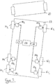
- a vehicle in this example a heavy goods vehicle comprising a tractor 10 and a trailer 12, fitted with a conventional electrical braking system (EBS) including anti-lock braking (ABS).
- EBS electrical braking system
- ABS anti-lock braking
- the trailer 12 has six wheels, three of which 14a, 14b, 14c are provided on a first side of the trailer 12, and three of which 16a, 16b, 16c are provided on a second side of the trailer 12.
- Each wheel is fitted with a wheel speed sensor (not shown) and a brake (not shown) which is operable by means of a brake actuator 18a, 18b, 18c, 20a, 20b, 20c.
- the braking system also includes a central electronic control unit (ECU) 22, which is electrically connected to each of the brake actuators 18a, 18b, 18c, 20a, 20b, 20c, the wheel speed sensors, and to a driver operated brake pedal or lever, as is conventional in such systems.
- ECU central electronic control unit
- the central ECU 22 is programmed to receive a braking demand signal from the brake pedal or lever, and transmit an appropriate braking signal to the brake actuators 18a, 18b, 18c, 20a, 20b, 20c so that the brake actuators 18a, 18b, 18c, 20a, 20b, 20c apply sufficient braking force to each vehicle wheel 14a, 14b, 14c, 16a, 16b, 16c to produce the desired vehicle braking.
- the central ECU also receives wheel speed signals from each of the wheel speed sensors, and is programmed to detect when any of the wheels locks, and to modify the braking signal in accordance with standard ABS control algorithms
- the brake actuators 18a, 18b, 18c, 20a, 20b, 20c are operated pneumatically, the electronic braking control signal generated by the central ECU being converted by a modulator to a pneumatic braking signal which is then transmitted to one or more of the brake actuators.
- the invention may, of course, be applied to a braking system in which the brake actuators are hydraulically or electrically operated.
- the trailer 12 is provided with two modulators, the first modulator 24 providing a pneumatic braking signal to the brake actuators 18a, 18b, 18c at the first side of the trailer 12, and the second modulator 26 providing a pneumatic braking signal to the brake actuators 20a, 20b, 20c at the second side of the trailer 12.
- the invention may, however, be applied to a trailer having a single modulator which provides a pneumatic braking signal to all the brake actuators or to a trailer having more than two modulators, so that the brake actuators associated with wheels on each side of the trailer are provided with a pneumatic braking signal from a plurality of modulators.
- the vehicle is also equipped with at least one accelerometer which is configured to measure the lateral acceleration of the vehicle.
- the accelerometer is connected to the central ECU 22, so that the central ECU 22 can detect when the vehicle is turning.
- the central ECU 22 is programmed such that when the lateral acceleration of the vehicle exceeds a predetermined value, it uses the lateral acceleration input to determine which way the vehicle is turning, and deactivates the ABS control of the wheels 14a, 14b, 14c on the inside of the vehicle's turning curve such that the wheel speed of each of the inside wheels 14a, 14b, 14c is not taken into consideration when determining whether an ABS intervention is required, i.e.
- the ABS system operates in "Select High” mode, and if it is determined that ABS control is required, the braking pressure to the outside wheels only is modified accordingly.
- the central ECU 22 also sends a braking signal to the modulator 24 providing a pneumatic braking signal to the brake actuators 18a, 18cb, 18c associated with these wheels 14a, 14b, 14c so as to apply a low level test braking pulse to each of the inside wheels 14a, 14b, 14c, and uses the wheel speed sensors to monitor the speed of each of the inside wheels 14a, 14b, 14c. This process is illustrated in Figure 1 . Normal ABS control is resumed after the test pulse has been applied.
- the magnitude of the braking force applied to each of the inside wheels 14a, 14b, 14c is such that with full or substantially full adhesion between the wheels 14a, 14b, 14c and the road, the braking force would have little impact on the wheel speed. If, however, adhesion between any of the inside wheels 14a, 14b, 14c and the road is reduced because the inside wheels 14a, 14b, 14c are tending to lift off the road, the test braking force is sufficiently high to cause the wheel in question to stop or slow down until there is a high level of slip between the road and the wheel.
- the system is configured such that the deceleration of the wheel is not taken into consideration when assessing whether a stability control intervention is required, and, if the central ECU detects that the slip between the road and any of any of the inside wheels 14a, 14b, 14c exceeds a predetermined amount following application of the test braking pulse, this is taken as an indication that lift of the inside wheels 14a, 14b, 14c is occurring and that there is a possibility that vehicle rollover may occur.
- the central ECU 22 is programmed to initiate a stability control braking intervention, and send a braking signal to the modulator 26 providing a pneumatic braking signal to the brake actuators 20a, 20b, 20c associated with the outside, non-lifting wheels 16a, 16b, 16c so as to slow the vehicle down, and hence reduce the likelihood of rollover.
- the control intervention could comprise other means of reducing the vehicle speed, such as throttling the vehicle engine.
- the central ECU may be programmed to generate a rollover alarm signal, which may comprises an audible or visual alarm or both, to alert the driver that braking is required to reduce the vehicle speed, and hence avoid rollover.
- ABS normal ABS control is resumed after the test braking pulse has been applied. There will inevitably be some delay before this occurs, and it is likely that for the first few milliseconds of the stability control intervention, the ABS is operated in "Select High” mode before normal ABS control is resumed.
- This can be advantageous as the inside wheels (low friction) wheels are more likely to lock as a result of the stability control braking than the outside wheels, and this means that, for the first few milliseconds of the stability control intervention, there is less likely to be an ABS control intervention (which would act to decrease the braking, and hence counteract the aim of reducing the vehicle speed to avoid rollover) than if the ABS is operating in the normal Select Low mode.
- the central ECU 22 is programmed to monitor the wheel speed of all of the inside wheels following the braking test pulse, and to initiate a stability control braking intervention or generate a rollover alarm signal when the results indicate that all of the inside wheels 14a, 14b, 14c have lifted off the ground. It will be appreciated however, that the central ECU 22 could be programmed to monitor the wheel speed of only a selected proportion of the inside wheels 14a, 14b, 14c and / or to initiate a stability control intervention or generate a rollover alarm signal when only one or a selected fraction of the inside wheels 14a, 14b, 14c are lifting off the ground.
- the duration of the stability control braking intervention is set by determining when the condition which prompted the initiation of the test braking pulse no longer exists, i.e. in this case, when the lateral acceleration of the vehicle falls below the predetermined value, the central ECU 22 acts to terminate application of the stability control braking force.
- the end of stability control braking intervention may be determined by, during the control intervention, deactivating the ABS control in relation to the inside wheels 14a, 14b, 14c, applying further low level braking test pulses to the inside wheels 14a, 14b, 14c and monitoring the speed of the inside wheels 14a, 14b, 14c in the same way as described above, in order to detect the reduction in slip when the adhesion is restored. Also as described above, if, in response to the test pulse, there is no significant increase in slip, it can be assumed that there is good contact between the wheel and the road, and therefore that the wheel in question is no longer lifting. The stability control braking intervention can thus be terminated when all, or at least some, of the inside wheels 14a, 14b, 14c are determined to be in contact with the road once more. This process is illustrated in Figure 2 .
- This embodiment of the invention may also be adapted to accommodate the need for a braking test pulse arising during driver braking. Should the driver apply the brakes, or the need for a braking test pulse arise during driver braking, in order to ensure that the braking system delivers a total braking level which meets the driver demand, the braking level can be distributed between the modulators 24, 26 on the trailer.
- the braking force applied to the inside wheels 14a, 14b, 14c as a result of driver demand may be reduced, and the braking force applied to the outside wheels 16a, 16b, 16c increased to compensate for the reduction in braking on the inside wheels 14a, 14b, 14c and give the desired total braking force.
- the system is configured to apply the driver specified braking without any modification, i.e. without applying a low level test pulse.
- the description so far relates to a vehicle with two modulators 24, 26 which control brake actuators 14a, 14b, 14c, 16a, 16b, 16c on opposite sides of the vehicle.
- the system operates slightly differently in a vehicle with only a single modulator, as, in this case, it is not possible for a different braking force to be applied to the wheels on one side of the vehicle to the other.
- the ABS system is deactivated for the inside wheels to the extent that the speed of the inside wheels is not taken into consideration when determining whether ABS control intervention is required, i.e. the ABS system operates in "Select High" mode, but the braking force on the inside wheels is altered along with the braking force on the outside wheels during any subsequent ABS control intervention.
Description
- The invention relates to a vehicle stability control system, particularly, but not exclusively, for use in heavy goods vehicles equipped with an anti-lock braking system (ABS).
- When a vehicle, in particular a heavy goods vehicle, rounds a corner, if the speed of the vehicle is sufficiently high, forces on the vehicle during cornering can cause the vehicle wheels on the inside of the curve travelled by the vehicle to lift off the road. Under certain conditions, this can cause the vehicle to overturn. It is therefore known to provide an automatic stability control system which acts to apply the vehicle brakes, and / or control the engine throttle to reduce the speed of the vehicle, when wheel lift is detected, in order to minimise the risk of rollover.
- One such system, for a vehicle comprising a tractor and trailer, is disclosed in
US617555 . In this prior art system, when it is determined that a situation with potential for rollover exists, for example by monitoring the lateral acceleration of the vehicle, a low-level brake test pulse is applied to the wheels and the ABS control unit is monitored. If the application of the test pulse results in an ABS control intervention, it is deduced that wheel lift has occurred, and a stability control intervention is initiated. - This system has the advantage that it may be used with any trailer fitted with ABS, without requiring any modification to the trailer. A disadvantage is that ABS control is typically tuned to give a fast response in order to prevent complete wheel lock-up, and is often configured to initiate an ABS control intervention not only when the wheels reach a defined level of slip, but also if the wheel deceleration is sufficiently high. As such, an ABS control intervention may be initiated as a result of noise in the wheel speed signal generated by obstructions in the road, or by brief changes in road friction. By initiating a rollover stability intervention in response to initiation of an ABS control intervention, this system can give a false alarm or trigger a stability control intervention under conditions when no rollover is likely.
- By deactivating the ABS system whilst testing to establish if a stability control intervention is required, and using wheel slip to determine if there is wheel lift, there are fewer false alarms when rollover is unlikely, and, where the method implements a stability control intervention, there is no initial reduction in braking pressure as a result of an ABS control intervention before the increase in braking pressure required to increase vehicle stability is achieved. Such a system is disclosed in
EP 1142768 , for example. - According to a first aspect of the invention, we provide a method of controlling travel of a vehicle equipped with an antilock braking system, the method comprising the steps of determining if there is potential for one or more wheels of the vehicle to lift off the ground, and if such a potential exists, deactivating the anti-lock braking system in respect of the wheels with the potential to lift off the ground so that the speed of these wheels is not taken into consideration when determining if anti-lock braking control is required, applying a low-level test braking force to the wheel or one of the wheels that has the potential to lift off the ground, monitoring the speed of the said wheel or wheels, and if the test braking force causes the speed of the or one or more of the monitored wheels to fall below a predetermined percentage of the vehicle speed, triggering a stability alarm signal and/or initiating a control intervention to reduce the vehicle speed, characterised in that if it is determined that there is potential for one or more of the wheels to lift off the ground during braking following braking demand from a driver of the vehicle, or if the driver issues a demand for braking during the application of a braking test pulse, where the braking demand requires a braking force which is below a predetermined level, the method also includes meeting the braking demand by increasing the braking force applied to the wheels without potential to lift off the ground by a greater amount than the braking force applied to the wheels with potential to lift off the ground.
- Preferably, the control intervention includes applying a controlled braking force to one or more of the wheels which do not have potential to lift off the ground so as to reduce the vehicle speed.
- Where the method includes initiating control intervention, the method further includes the steps of monitoring the potential for one or more of the vehicle wheels to lift off the ground, and ceasing the control intervention when the potential for one or more of the vehicle wheels to lift off the ground is no longer present. Alternatively, the method may include the steps of applying further low level test braking pulses to the wheel or wheels which has the potential to lift off the ground, monitoring the speed of the or each of the said wheels, and ceasing the control intervention when the speed of the or each of the monitored wheels does not change significantly relative to the speed of the vehicle following the application of the test braking pulse.
- The method of determination of the potential for one or more of the vehicle wheels to lift off the ground may include measurement of the lateral acceleration of the vehicle.
- According to a second aspect of the invention we provide a vehicle braking system comprising an electronic control unit of an electronic braking system including antilock braking control, the control unit being adapted to provide a braking signal to a plurality of brake actuators associated with wheels on first and second sides of the vehicle, wherein the control unit has the capability of determining if there is potential for one or more wheels of the vehicle to lift off the ground, and if such a potential exists, deactivating the anti-lock braking system in respect of the wheels with the potential to lift off the ground so that the speed of these wheels is not taken into consideration when determining if anti-lock braking control is required, generating a braking signal to apply a low-level test braking force to the wheel or one of the wheels that has the potential to lift off the ground, monitoring the speed of the said wheel or wheels, and if the test braking force causes the speed of the or one or more of the monitored wheels to fall below a predetermined percentage of the vehicle speed, triggering a stability alarm signal and/or initiating a control intervention to reduce the vehicle speed, characterised in that the control unit is also adapted to, if it determines that there is potential for one or more of the wheels to lift off the ground during braking following braking demand from a driver of the vehicle or that the driver issues a demand for braking during the application of a test braking pulse, determine whether the braking demand requires a braking force which is below a pre-determined level, and if it is, to meet the braking demand by increasing the braking force applied to the wheels without potential to lift off the ground by a greater amount than the braking force applied to the wheels with the potential to lift off the ground.
- An embodiment of the invention will now be described, by way of example only, with reference to the following drawings:
-
FIGURE 1 is a flow chart illustrating a braking control method according to the first aspect of the invention, -
FIGURE 2 is a further flow chart illustrating in more detail an alternative embodiment of the "Alarm signal / stabilization" step in the flow chart ofFigure 1 , -
FIGURE 3 is a schematic illustration of a vehicle equipped with a braking control system according to a second aspect of the invention. - Referring first to
Figure 3 , there is provided a vehicle, in this example a heavy goods vehicle comprising atractor 10 and atrailer 12, fitted with a conventional electrical braking system (EBS) including anti-lock braking (ABS). Thetrailer 12 has six wheels, three of which 14a, 14b, 14c are provided on a first side of thetrailer 12, and three of which 16a, 16b, 16c are provided on a second side of thetrailer 12. Each wheel is fitted with a wheel speed sensor (not shown) and a brake (not shown) which is operable by means of abrake actuator brake actuators - The
central ECU 22 is programmed to receive a braking demand signal from the brake pedal or lever, and transmit an appropriate braking signal to thebrake actuators brake actuators vehicle wheel brake actuators - Moreover, in this embodiment of the invention, the
trailer 12 is provided with two modulators, thefirst modulator 24 providing a pneumatic braking signal to thebrake actuators 18a, 18b, 18c at the first side of thetrailer 12, and thesecond modulator 26 providing a pneumatic braking signal to thebrake actuators trailer 12. It will be appreciated that the invention may, however, be applied to a trailer having a single modulator which provides a pneumatic braking signal to all the brake actuators or to a trailer having more than two modulators, so that the brake actuators associated with wheels on each side of the trailer are provided with a pneumatic braking signal from a plurality of modulators. - The vehicle is also equipped with at least one accelerometer which is configured to measure the lateral acceleration of the vehicle. The accelerometer is connected to the
central ECU 22, so that thecentral ECU 22 can detect when the vehicle is turning. Thecentral ECU 22 is programmed such that when the lateral acceleration of the vehicle exceeds a predetermined value, it uses the lateral acceleration input to determine which way the vehicle is turning, and deactivates the ABS control of thewheels 14a, 14b, 14c on the inside of the vehicle's turning curve such that the wheel speed of each of theinside wheels 14a, 14b, 14c is not taken into consideration when determining whether an ABS intervention is required, i.e. the ABS system operates in "Select High" mode, and if it is determined that ABS control is required, the braking pressure to the outside wheels only is modified accordingly. Thecentral ECU 22 also sends a braking signal to themodulator 24 providing a pneumatic braking signal to thebrake actuators 18a, 18cb, 18c associated with thesewheels 14a, 14b, 14c so as to apply a low level test braking pulse to each of theinside wheels 14a, 14b, 14c, and uses the wheel speed sensors to monitor the speed of each of theinside wheels 14a, 14b, 14c. This process is illustrated inFigure 1 . Normal ABS control is resumed after the test pulse has been applied. - The magnitude of the braking force applied to each of the
inside wheels 14a, 14b, 14c is such that with full or substantially full adhesion between thewheels 14a, 14b, 14c and the road, the braking force would have little impact on the wheel speed. If, however, adhesion between any of theinside wheels 14a, 14b, 14c and the road is reduced because theinside wheels 14a, 14b, 14c are tending to lift off the road, the test braking force is sufficiently high to cause the wheel in question to stop or slow down until there is a high level of slip between the road and the wheel. It has been found that the application of the test braking pulse to a non-lifting wheel can cause an initial rapid deceleration of the wheel, but this initial deceleration is short lived, and does not result in any significant degree of wheel slip. As such, the system is configured such that the deceleration of the wheel is not taken into consideration when assessing whether a stability control intervention is required, and, if the central ECU detects that the slip between the road and any of any of theinside wheels 14a, 14b, 14c exceeds a predetermined amount following application of the test braking pulse, this is taken as an indication that lift of theinside wheels 14a, 14b, 14c is occurring and that there is a possibility that vehicle rollover may occur. - In this embodiment of the invention, if wheel lift is detected, the
central ECU 22 is programmed to initiate a stability control braking intervention, and send a braking signal to themodulator 26 providing a pneumatic braking signal to thebrake actuators non-lifting wheels 16a, 16b, 16c so as to slow the vehicle down, and hence reduce the likelihood of rollover. It will be appreciated, however, that the control intervention could comprise other means of reducing the vehicle speed, such as throttling the vehicle engine. Alternatively, if wheel lift is detected, the central ECU may be programmed to generate a rollover alarm signal, which may comprises an audible or visual alarm or both, to alert the driver that braking is required to reduce the vehicle speed, and hence avoid rollover. - As mentioned above, normal ABS control is resumed after the test braking pulse has been applied. There will inevitably be some delay before this occurs, and it is likely that for the first few milliseconds of the stability control intervention, the ABS is operated in "Select High" mode before normal ABS control is resumed. This can be advantageous as the inside wheels (low friction) wheels are more likely to lock as a result of the stability control braking than the outside wheels, and this means that, for the first few milliseconds of the stability control intervention, there is less likely to be an ABS control intervention (which would act to decrease the braking, and hence counteract the aim of reducing the vehicle speed to avoid rollover) than if the ABS is operating in the normal Select Low mode.
- Also in this embodiment of the invention, the
central ECU 22 is programmed to monitor the wheel speed of all of the inside wheels following the braking test pulse, and to initiate a stability control braking intervention or generate a rollover alarm signal when the results indicate that all of theinside wheels 14a, 14b, 14c have lifted off the ground. It will be appreciated however, that thecentral ECU 22 could be programmed to monitor the wheel speed of only a selected proportion of theinside wheels 14a, 14b, 14c and / or to initiate a stability control intervention or generate a rollover alarm signal when only one or a selected fraction of theinside wheels 14a, 14b, 14c are lifting off the ground. - The duration of the stability control braking intervention is set by determining when the condition which prompted the initiation of the test braking pulse no longer exists, i.e. in this case, when the lateral acceleration of the vehicle falls below the predetermined value, the
central ECU 22 acts to terminate application of the stability control braking force. - It will be appreciated however, that this is likely to result in over-braking of the vehicle, as the control intervention will continue after the
inside wheels 14a, 14b, 14c have returned to the road, and after rollover ceases to be a possibility. This can cause irritation to the driver of the vehicle. The duration of the stability control braking intervention need not be set in this way, however. - In an alternative embodiment of the invention, the end of stability control braking intervention may be determined by, during the control intervention, deactivating the ABS control in relation to the
inside wheels 14a, 14b, 14c, applying further low level braking test pulses to theinside wheels 14a, 14b, 14c and monitoring the speed of theinside wheels 14a, 14b, 14c in the same way as described above, in order to detect the reduction in slip when the adhesion is restored. Also as described above, if, in response to the test pulse, there is no significant increase in slip, it can be assumed that there is good contact between the wheel and the road, and therefore that the wheel in question is no longer lifting. The stability control braking intervention can thus be terminated when all, or at least some, of theinside wheels 14a, 14b, 14c are determined to be in contact with the road once more. This process is illustrated inFigure 2 . - This embodiment of the invention may also be adapted to accommodate the need for a braking test pulse arising during driver braking. Should the driver apply the brakes, or the need for a braking test pulse arise during driver braking, in order to ensure that the braking system delivers a total braking level which meets the driver demand, the braking level can be distributed between the
modulators inside wheels 14a, 14b, 14c, the braking force applied to theinside wheels 14a, 14b, 14c as a result of driver demand may be reduced, and the braking force applied to theoutside wheels 16a, 16b, 16c increased to compensate for the reduction in braking on theinside wheels 14a, 14b, 14c and give the desired total braking force. - If the driver braking demand is sufficiently high, however, it may not be possible to increase the braking force on the
outside wheels 16a, 16b, 16c enough to compensate for the reduction required to allow for a low level braking test pulse on theinside wheels 14a, 14b, 14c. In this case, the high level of braking demand is likely to slow the vehicle sufficiently to avoid rollover, and at such levels, the system is configured to apply the driver specified braking without any modification, i.e. without applying a low level test pulse. - As mentioned above, the description so far relates to a vehicle with two
modulators brake actuators - When used in this specification and claims, the terms "comprises" and "comprising" and variations thereof mean that the specified features, steps or integers are included. The terms are not to be interpreted to exclude the presence of other features, steps or components.
- The features disclosed in the foregoing description, or the following claims, or the accompanying drawings, expressed in their specific forms or in terms of a means for performing the disclosed function, or a method or process for attaining the disclosed result, as appropriate, may, separately, or in any combination of such features, be utilised for realising the invention in diverse forms thereof.
Claims (6)
- A method of controlling travel of a vehicle (12) equipped with an antilock braking system, the method comprising the steps of determining if there is potential for one or more wheels of the vehicle (12) to lift off the ground, and if such a potential exists, deactivating the anti-lock braking system in respect of the wheels (14a, 14b, 14c) with the potential to lift off the ground so that the speed of these wheels (14a, 14b, 14c) is not taken into consideration when determining if anti-lock braking control is required, applying a low-level test braking force to the wheel or one of the wheels (14a, 14b, 14c) that has the potential to lift off the ground, monitoring the speed of the said wheel or wheels (14a, 14b, 14c), and if the test braking force causes the speed of the or one or more of the monitored wheels (14a, 14b, 14c) to fall below a predetermined percentage of the vehicle speed, triggering a stability alarm signal and/or initiating a control intervention to reduce the vehicle speed, characterised in that if it is determined that there is potential for one or more of the wheels (14a, 14b, 14c, 16a, 16b, 16c) to lift off the ground during braking following braking demand from a driver of the vehicle (10, 12), or if the driver issues a demand for braking during the application of a braking test pulse, where the braking demand requires a braking force which is below a predetermined level, the method also includes meeting the braking demand by increasing the braking force applied to the wheels (16a, 16b, 16c) without potential to lift off the ground by a greater amount than the braking force applied to the wheels (14a, 14b, 14c) with potential to lift off the ground.
- The method according to claim 1 wherein the control intervention includes applying a controlled braking force to one or more of the wheels (16a, 16b, 16c) which do not have potential to lift off the ground so as to reduce the vehicle speed.
- A method according to claim 1 wherein, where the method includes initiating a control intervention, the method further includes the steps of monitoring the potential for one or more of the vehicle wheels (14a, 14b, 14c) to lift off the ground, and ceasing the control intervention when the potential for one or more of the vehicle wheels (14a, 14b, 14c) to lift off the ground is no longer present.
- A method according to claim 1 wherein the method may include the steps of applying further low level test braking pulses to the wheel or wheels (14a, 14b, 14c) which has the potential to lift off the ground, monitoring the speed of the or each of the said wheels (14a, 14b, 14c), and ceasing the control intervention when the speed of the or each of the monitored wheels (14a, 14b, 14c) does not change significantly relatively to the speed of the vehicle (12) following the application of the test braking pulse.
- A method according to any preceding claim wherein the method of determination of the potential for one or more of the vehicle wheels (14a, 14b, 14c, 16a, 16b, 16c) to lift off the ground includes measurement of the lateral acceleration of the vehicle.
- A vehicle braking system comprising an electronic control unit (22) of an electronic braking system including antilock braking control, the control unit (22) being adapted to provide a braking signal to a plurality of brake actuators (18a, 18b, 18c, 20a, 20b, 20c) associated with wheels (14a, 14b, 14c, 16a, 16b, 16c) on first and second sides of the vehicle (12), wherein the control unit (22) has the capability of determining if there is potential for one or more wheels (14a, 14b, 14c, 16a, 16b, 16c) of the vehicle to lift off the ground, and if such a potential exists, deactivating the anti-lock braking system in respect of the wheels (14a, 14b, 14c) with the potential to lift off the ground so that the speed of these wheels (14a, 14b, 14c) is not taken into consideration when determining if anti-lock braking control is required, generating a braking signal to apply a low-level test braking force to the wheel or one of the wheels (14a, 14b, 14c) that has the potential to lift off the ground, monitoring the speed of the said wheel or wheels (14a, 14b, 14c), and if the test braking force causes the speed of the or one or more of the monitored wheels (14a, 14b, 14c) to fall below a predetermined percentage of the vehicle speed, triggering a stability alarm signal and/or initiating a control intervention to reduce the vehicle speed, characterised in that the control unit (22) is also adapted to, if it determines that there is potential for one or more of the wheels (14a, 14b, 14c) to lift off the ground during braking following braking demand from a driver of the vehicle (10, 12) or that the driver issues a demand for braking during the application of a test braking pulse, determine whether the braking demand requires a braking force which is below a pre-determined level, and if it is, to meet the braking demand by increasing the braking force applied to the wheels (16a, 16b, 16c) without potential to lift off the ground by a greater amount than the braking force applied to the wheels (14a, 14b, 14c) with the potential to lift off the ground.
Applications Claiming Priority (2)
| Application Number | Priority Date | Filing Date | Title |
|---|---|---|---|
| GB0721463A GB2454223B (en) | 2007-11-01 | 2007-11-01 | Vehicle stability control method |
| PCT/GB2008/003583 WO2009056799A1 (en) | 2007-11-01 | 2008-10-23 | Vehicle stability control method |
Publications (3)
| Publication Number | Publication Date |
|---|---|
| EP2214939A1 EP2214939A1 (en) | 2010-08-11 |
| EP2214939B1 true EP2214939B1 (en) | 2016-04-13 |
| EP2214939B8 EP2214939B8 (en) | 2016-06-01 |
Family
ID=38834672
Family Applications (1)
| Application Number | Title | Priority Date | Filing Date |
|---|---|---|---|
| EP08843422.0A Active EP2214939B8 (en) | 2007-11-01 | 2008-10-23 | Vehicle stability control method |
Country Status (6)
| Country | Link |
|---|---|
| US (1) | US8768594B2 (en) |
| EP (1) | EP2214939B8 (en) |
| CN (1) | CN101842274A (en) |
| BR (1) | BRPI0819243B1 (en) |
| GB (1) | GB2454223B (en) |
| WO (1) | WO2009056799A1 (en) |
Cited By (1)
| Publication number | Priority date | Publication date | Assignee | Title |
|---|---|---|---|---|
| US11654874B2 (en) | 2017-08-25 | 2023-05-23 | Haldex Brake Products Ab | Braking system |
Families Citing this family (7)
| Publication number | Priority date | Publication date | Assignee | Title |
|---|---|---|---|---|
| DE102011102927A1 (en) * | 2011-05-31 | 2012-12-06 | GM Global Technology Operations LLC (n. d. Gesetzen des Staates Delaware) | Method for operating a driver assistance system of a motor vehicle and driver assistance system for a motor vehicle |
| DE102011121775B3 (en) | 2011-12-21 | 2013-01-31 | Brose Fahrzeugteile Gmbh & Co. Kg, Hallstadt | Control system for controlling e.g. motorized side door of motor car, has distance sensors with dummy portions such that sensors comprise no sensitivity or smaller sensitivity compared to region of each sensor adjacent to dummy portions |
| GB2499438B (en) * | 2012-02-17 | 2018-10-17 | Haldex Brake Prod Ab | Method of vehicle stability control |
| DE102012013065A1 (en) | 2012-07-02 | 2014-01-02 | Brose Fahrzeugteile Gmbh & Co. Kg, Hallstadt | Method for controlling a closure element arrangement of a motor vehicle |
| DE102013018593B4 (en) * | 2013-11-07 | 2022-04-21 | Brose Fahrzeugteile Se & Co. Kommanditgesellschaft, Bamberg | Method for controlling a closure element arrangement of a motor vehicle |
| CN104527625A (en) * | 2014-12-29 | 2015-04-22 | 芜湖伯特利汽车安全系统有限公司 | ABS and method for conducting driving brake pipeline failure test through ABS |
| CN104819856A (en) * | 2015-04-29 | 2015-08-05 | 中国铁道科学研究院 | Train bogie transverse stability detection method and device |
Citations (17)
| Publication number | Priority date | Publication date | Assignee | Title |
|---|---|---|---|---|
| EP0051801A2 (en) | 1980-11-11 | 1982-05-19 | ALFRED TEVES GmbH | Antiskidsystem |
| US5322355A (en) | 1987-04-01 | 1994-06-21 | Robert Bosch Gmbh | Anti-skid brake control system |
| DE19522632A1 (en) | 1995-06-22 | 1997-01-02 | Teves Gmbh Alfred | Process for improving the control behavior of an anti-lock control system |
| DE19602879C1 (en) | 1996-01-29 | 1997-08-07 | Knorr Bremse Systeme | Method for detecting the risk of a vehicle tipping over |
| DE19632943A1 (en) | 1996-08-16 | 1998-02-19 | Daimler Benz Ag | Method for operating a motor vehicle with brake interventions that stabilize driving |
| EP1142768A2 (en) | 2000-04-05 | 2001-10-10 | WABCO GmbH & CO. OHG | Method for preventing the overturning of a vehicle about its longitudinal axis |
| WO2002022416A1 (en) | 2000-09-18 | 2002-03-21 | Knorr-Bremse Systeme für Nutzfahrzeuge GmbH | Method for estimating the overturn risk of a vehicle |
| EP1030798B1 (en) | 1997-11-22 | 2002-05-02 | Robert Bosch Gmbh | Method and device for stabilising motor vehicle tilt |
| WO2002053427A1 (en) | 2000-12-30 | 2002-07-11 | Robert Bosch Gmbh | System and method for monitoring the traction of a motor vehicle |
| US20030225499A1 (en) | 2002-05-30 | 2003-12-04 | Gusztav Holler | Antilock braking system based roll over prevention |
| US20040167701A1 (en) | 2003-02-26 | 2004-08-26 | Mattson Keith Glenn | Active driven wheel lift identification for an automotive vehicle |
| EP1459949A1 (en) | 2003-03-18 | 2004-09-22 | WABCO GmbH & CO. OHG | Method for preventing the overturning of a vehicle |
| US20050137767A1 (en) | 2003-12-23 | 2005-06-23 | Goebels Hermann J. | Roll stability control system |
| EP1571058A1 (en) * | 2004-03-03 | 2005-09-07 | WABCO GmbH & Co. OHG | Braking method for a vehicle |
| US7109856B2 (en) | 2000-09-25 | 2006-09-19 | Ford Global Technologies, Llc | Wheel lifted and grounded identification for an automotive vehicle |
| US20060261937A1 (en) | 2000-09-25 | 2006-11-23 | Jianbo Lu | Wheel lifted and grounded identification for an automotive vehicle |
| EP1040035B1 (en) | 1997-12-16 | 2007-03-14 | Continental Teves AG & Co. oHG | Method and device for limiting transversal acceleration in a motor vehicle |
Family Cites Families (27)
| Publication number | Priority date | Publication date | Assignee | Title |
|---|---|---|---|---|
| DE2133547C2 (en) * | 1971-07-06 | 1982-01-21 | Daimler-Benz Ag, 7000 Stuttgart | Brake force control for motor vehicles |
| JP2618250B2 (en) * | 1987-12-22 | 1997-06-11 | 富士重工業株式会社 | Traction control device |
| NL9400843A (en) | 1994-05-24 | 1996-01-02 | Tno | System for determining the stability of a vehicle. |
| US5742918A (en) * | 1996-04-26 | 1998-04-21 | Ford Global Technologies, Inc. | Method and apparatus for dynamically compensating a lateral acceleration of a motor vehicle |
| JPH10119743A (en) * | 1996-10-23 | 1998-05-12 | Aisin Seiki Co Ltd | Motion control device for vehicle |
| US5825284A (en) * | 1996-12-10 | 1998-10-20 | Rollover Operations, Llc | System and method for the detection of vehicle rollover conditions |
| DE19736328A1 (en) * | 1997-08-21 | 1999-02-25 | Bayerische Motoren Werke Ag | Controlling accident protection triggering devices in motor vehicle |
| DE19751925A1 (en) * | 1997-11-22 | 1999-05-27 | Bosch Gmbh Robert | Tilt tendency detection method for vehicles for stabilization and roll-over prevention of heavy duty vehicle |
| DE19751839A1 (en) * | 1997-11-22 | 1999-05-27 | Bosch Gmbh Robert | Tilt tendency detection in vehicle |
| DE19802041A1 (en) * | 1998-01-21 | 1999-07-22 | Bosch Gmbh Robert | Procedure for stabilizing car to avoid tipping over, especially for about axis oriented in car's longitudinal direction |
| US6002975A (en) * | 1998-02-06 | 1999-12-14 | Delco Electronics Corporation | Vehicle rollover sensing |
| GB9812264D0 (en) * | 1998-06-09 | 1998-08-05 | Rover Group | Vehicle roll control |
| DE19827882A1 (en) * | 1998-06-23 | 1999-12-30 | Bosch Gmbh Robert | Procedure for stabilising vehicle, especially for avoiding its tipping over about longitudinal axis and/or its skidding in transverse direction |
| US6438464B1 (en) * | 1998-07-16 | 2002-08-20 | Continental Teves Ag & Co., Ohg | Method and device for detecting the overturning hazard of a motor vehicle |
| US6278930B1 (en) * | 1999-06-01 | 2001-08-21 | Toyota Jidosha Kabushiki Kaisha | Device for controlling spin/driftout of vehicle compatibly with roll control |
| US6304805B1 (en) * | 1999-07-21 | 2001-10-16 | Denso Corporation | Vehicle behavior estimating and controlling method and system as well as body slip angle estimating method and system |
| DE10026688C1 (en) * | 2000-05-30 | 2001-09-13 | Knorr Bremse Systeme | Method and device for determining pick-up pressure of vehicle brakes applies a test pressure to brakes being examined by generating a test pressure indicator signal before and after generating test pressure. |
| US7132937B2 (en) * | 2000-09-25 | 2006-11-07 | Ford Global Technologies, Llc | Wheel lift identification for an automotive vehicle using passive and active detection |
| US6397127B1 (en) * | 2000-09-25 | 2002-05-28 | Ford Global Technologies, Inc. | Steering actuated wheel lift identification for an automotive vehicle |
| US6904350B2 (en) * | 2000-09-25 | 2005-06-07 | Ford Global Technologies, Llc | System for dynamically determining the wheel grounding and wheel lifting conditions and their applications in roll stability control |
| US6356188B1 (en) * | 2000-09-25 | 2002-03-12 | Ford Global Technologies, Inc. | Wheel lift identification for an automotive vehicle |
| JP2002107371A (en) * | 2000-09-29 | 2002-04-10 | Toyota Motor Corp | Rotating state detecting device for wheel |
| US6498976B1 (en) * | 2000-10-30 | 2002-12-24 | Freightliner Llc | Vehicle operator advisor system and method |
| US7302331B2 (en) * | 2002-08-01 | 2007-11-27 | Ford Global Technologies, Inc. | Wheel lift identification for an automotive vehicle |
| US20040024505A1 (en) * | 2002-08-05 | 2004-02-05 | Salib Albert Chenouda | System and method for operating a rollover control system in a transition to a rollover condition |
| US7085642B2 (en) * | 2002-08-05 | 2006-08-01 | Ford Global Technologies, Llc | Method and system for correcting sensor offsets |
| US8191975B2 (en) * | 2005-12-15 | 2012-06-05 | Bendix Commercial Vehicle Systems Llc | Single channel roll stability system |
-
2007
- 2007-11-01 GB GB0721463A patent/GB2454223B/en active Active
-
2008
- 2008-10-23 CN CN200880114508A patent/CN101842274A/en active Pending
- 2008-10-23 EP EP08843422.0A patent/EP2214939B8/en active Active
- 2008-10-23 BR BRPI0819243A patent/BRPI0819243B1/en not_active IP Right Cessation
- 2008-10-23 WO PCT/GB2008/003583 patent/WO2009056799A1/en active Application Filing
-
2010
- 2010-04-30 US US12/771,493 patent/US8768594B2/en active Active
Patent Citations (17)
| Publication number | Priority date | Publication date | Assignee | Title |
|---|---|---|---|---|
| EP0051801A2 (en) | 1980-11-11 | 1982-05-19 | ALFRED TEVES GmbH | Antiskidsystem |
| US5322355A (en) | 1987-04-01 | 1994-06-21 | Robert Bosch Gmbh | Anti-skid brake control system |
| DE19522632A1 (en) | 1995-06-22 | 1997-01-02 | Teves Gmbh Alfred | Process for improving the control behavior of an anti-lock control system |
| DE19602879C1 (en) | 1996-01-29 | 1997-08-07 | Knorr Bremse Systeme | Method for detecting the risk of a vehicle tipping over |
| DE19632943A1 (en) | 1996-08-16 | 1998-02-19 | Daimler Benz Ag | Method for operating a motor vehicle with brake interventions that stabilize driving |
| EP1030798B1 (en) | 1997-11-22 | 2002-05-02 | Robert Bosch Gmbh | Method and device for stabilising motor vehicle tilt |
| EP1040035B1 (en) | 1997-12-16 | 2007-03-14 | Continental Teves AG & Co. oHG | Method and device for limiting transversal acceleration in a motor vehicle |
| EP1142768A2 (en) | 2000-04-05 | 2001-10-10 | WABCO GmbH & CO. OHG | Method for preventing the overturning of a vehicle about its longitudinal axis |
| WO2002022416A1 (en) | 2000-09-18 | 2002-03-21 | Knorr-Bremse Systeme für Nutzfahrzeuge GmbH | Method for estimating the overturn risk of a vehicle |
| US7109856B2 (en) | 2000-09-25 | 2006-09-19 | Ford Global Technologies, Llc | Wheel lifted and grounded identification for an automotive vehicle |
| US20060261937A1 (en) | 2000-09-25 | 2006-11-23 | Jianbo Lu | Wheel lifted and grounded identification for an automotive vehicle |
| WO2002053427A1 (en) | 2000-12-30 | 2002-07-11 | Robert Bosch Gmbh | System and method for monitoring the traction of a motor vehicle |
| US20030225499A1 (en) | 2002-05-30 | 2003-12-04 | Gusztav Holler | Antilock braking system based roll over prevention |
| US20040167701A1 (en) | 2003-02-26 | 2004-08-26 | Mattson Keith Glenn | Active driven wheel lift identification for an automotive vehicle |
| EP1459949A1 (en) | 2003-03-18 | 2004-09-22 | WABCO GmbH & CO. OHG | Method for preventing the overturning of a vehicle |
| US20050137767A1 (en) | 2003-12-23 | 2005-06-23 | Goebels Hermann J. | Roll stability control system |
| EP1571058A1 (en) * | 2004-03-03 | 2005-09-07 | WABCO GmbH & Co. OHG | Braking method for a vehicle |
Cited By (1)
| Publication number | Priority date | Publication date | Assignee | Title |
|---|---|---|---|---|
| US11654874B2 (en) | 2017-08-25 | 2023-05-23 | Haldex Brake Products Ab | Braking system |
Also Published As
| Publication number | Publication date |
|---|---|
| BRPI0819243B1 (en) | 2018-12-26 |
| EP2214939B8 (en) | 2016-06-01 |
| US8768594B2 (en) | 2014-07-01 |
| GB2454223B (en) | 2011-09-21 |
| GB2454223A (en) | 2009-05-06 |
| GB0721463D0 (en) | 2007-12-12 |
| EP2214939A1 (en) | 2010-08-11 |
| BRPI0819243A2 (en) | 2015-05-05 |
| CN101842274A (en) | 2010-09-22 |
| US20100211283A1 (en) | 2010-08-19 |
| WO2009056799A1 (en) | 2009-05-07 |
Similar Documents
| Publication | Publication Date | Title |
|---|---|---|
| EP2214939B1 (en) | Vehicle stability control method | |
| US6957873B2 (en) | Method for regulating the driving stability of a vehicle | |
| US5669678A (en) | Process and apparatus for determining the application pressures and characteristic brake values of a vehicle | |
| US6553284B2 (en) | Process to prevent the overturning of a vehicle around its longitudinal axis | |
| JP4693765B2 (en) | Method and system for controlling driving stability of a vehicle and use of this system | |
| US6356188B1 (en) | Wheel lift identification for an automotive vehicle | |
| EP2504207B1 (en) | Method of operating a trailer braking system | |
| US20080221758A1 (en) | Method and Device for Actuating a Vehicle Occupant Protection Means | |
| JP2006518302A5 (en) | ||
| JP2004131080A (en) | Method for controlling braking device for tractor-trailer combination | |
| EP1386804B1 (en) | Wheel lift identification for an automotive vehicle | |
| US20080133101A1 (en) | Method and Device for Suppressing a Lateral Rollover Tendency of a Vehicle | |
| JP2001130390A (en) | Control method and device for vehicle | |
| US4733920A (en) | Motor vehicle brake antilocking system | |
| US7216026B2 (en) | Vehicle-dynamics control method and system for a vehicle train | |
| US7698034B2 (en) | Integrating active front steering and vehicle stability brake control | |
| JP2007513002A (en) | Method and apparatus for stabilizing a vehicle in a dangerous driving situation | |
| GB2498613A (en) | Tractor and trailer stabilization that applies trailer brakes based on vehicle speed, steering angle and steering angle velocity | |
| WO2004110836A1 (en) | Method and arrangement for controlling brakes in a vehicle or a combination of vehicles | |
| KR20180090341A (en) | Control method of hydraulic brake system and control device thereof | |
| WO1995003964A1 (en) | Reduced brake switch dependence control method and system for vehicle anti-lock brake system | |
| KR101003713B1 (en) | Method to sense Fish-hook test mode of ESP | |
| KR0130373Y1 (en) | Anti-lock brake system | |
| JPH08290763A (en) | Braking force distributing device |
Legal Events
| Date | Code | Title | Description |
|---|---|---|---|
| PUAI | Public reference made under article 153(3) epc to a published international application that has entered the european phase |
Free format text: ORIGINAL CODE: 0009012 |
|
| 17P | Request for examination filed |
Effective date: 20100413 |
|
| AK | Designated contracting states |
Kind code of ref document: A1 Designated state(s): AT BE BG CH CY CZ DE DK EE ES FI FR GB GR HR HU IE IS IT LI LT LU LV MC MT NL NO PL PT RO SE SI SK TR |
|
| AX | Request for extension of the european patent |
Extension state: AL BA MK RS |
|
| DAX | Request for extension of the european patent (deleted) | ||
| RAP1 | Party data changed (applicant data changed or rights of an application transferred) |
Owner name: HALDEX BRAKE PRODUCTS LIMITED |
|
| 17Q | First examination report despatched |
Effective date: 20150219 |
|
| GRAP | Despatch of communication of intention to grant a patent |
Free format text: ORIGINAL CODE: EPIDOSNIGR1 |
|
| INTG | Intention to grant announced |
Effective date: 20151217 |
|
| GRAS | Grant fee paid |
Free format text: ORIGINAL CODE: EPIDOSNIGR3 |
|
| GRAA | (expected) grant |
Free format text: ORIGINAL CODE: 0009210 |
|
| GRAT | Correction requested after decision to grant or after decision to maintain patent in amended form |
Free format text: ORIGINAL CODE: EPIDOSNCDEC |
|
| AK | Designated contracting states |
Kind code of ref document: B1 Designated state(s): AT BE BG CH CY CZ DE DK EE ES FI FR GB GR HR HU IE IS IT LI LT LU LV MC MT NL NO PL PT RO SE SI SK TR |
|
| REG | Reference to a national code |
Ref country code: GB Ref legal event code: FG4D |
|
| REG | Reference to a national code |
Ref country code: AT Ref legal event code: REF Ref document number: 789760 Country of ref document: AT Kind code of ref document: T Effective date: 20160415 Ref country code: CH Ref legal event code: EP |
|
| RBV | Designated contracting states (corrected) |
Designated state(s): AT BE BG CH CY CZ DE DK EE ES FI FR GR HR HU IE IS IT LI LT LU LV MC MT NL NO PL PT RO SE SI SK TR |
|
| REG | Reference to a national code |
Ref country code: IE Ref legal event code: FG4D |
|
| REG | Reference to a national code |
Ref country code: DE Ref legal event code: R096 Ref document number: 602008043613 Country of ref document: DE |
|
| REG | Reference to a national code |
Ref country code: SE Ref legal event code: TRGR |
|
| REG | Reference to a national code |
Ref country code: LT Ref legal event code: MG4D |
|
| REG | Reference to a national code |
Ref country code: AT Ref legal event code: MK05 Ref document number: 789760 Country of ref document: AT Kind code of ref document: T Effective date: 20160413 |
|
| REG | Reference to a national code |
Ref country code: FR Ref legal event code: PLFP Year of fee payment: 9 |
|
| REG | Reference to a national code |
Ref country code: NL Ref legal event code: MP Effective date: 20160413 |
|
| PG25 | Lapsed in a contracting state [announced via postgrant information from national office to epo] |
Ref country code: NL Free format text: LAPSE BECAUSE OF FAILURE TO SUBMIT A TRANSLATION OF THE DESCRIPTION OR TO PAY THE FEE WITHIN THE PRESCRIBED TIME-LIMIT Effective date: 20160413 Ref country code: NO Free format text: LAPSE BECAUSE OF FAILURE TO SUBMIT A TRANSLATION OF THE DESCRIPTION OR TO PAY THE FEE WITHIN THE PRESCRIBED TIME-LIMIT Effective date: 20160713 Ref country code: PL Free format text: LAPSE BECAUSE OF FAILURE TO SUBMIT A TRANSLATION OF THE DESCRIPTION OR TO PAY THE FEE WITHIN THE PRESCRIBED TIME-LIMIT Effective date: 20160413 Ref country code: FI Free format text: LAPSE BECAUSE OF FAILURE TO SUBMIT A TRANSLATION OF THE DESCRIPTION OR TO PAY THE FEE WITHIN THE PRESCRIBED TIME-LIMIT Effective date: 20160413 Ref country code: LT Free format text: LAPSE BECAUSE OF FAILURE TO SUBMIT A TRANSLATION OF THE DESCRIPTION OR TO PAY THE FEE WITHIN THE PRESCRIBED TIME-LIMIT Effective date: 20160413 |
|
| PG25 | Lapsed in a contracting state [announced via postgrant information from national office to epo] |
Ref country code: HR Free format text: LAPSE BECAUSE OF FAILURE TO SUBMIT A TRANSLATION OF THE DESCRIPTION OR TO PAY THE FEE WITHIN THE PRESCRIBED TIME-LIMIT Effective date: 20160413 Ref country code: GR Free format text: LAPSE BECAUSE OF FAILURE TO SUBMIT A TRANSLATION OF THE DESCRIPTION OR TO PAY THE FEE WITHIN THE PRESCRIBED TIME-LIMIT Effective date: 20160714 Ref country code: AT Free format text: LAPSE BECAUSE OF FAILURE TO SUBMIT A TRANSLATION OF THE DESCRIPTION OR TO PAY THE FEE WITHIN THE PRESCRIBED TIME-LIMIT Effective date: 20160413 Ref country code: ES Free format text: LAPSE BECAUSE OF FAILURE TO SUBMIT A TRANSLATION OF THE DESCRIPTION OR TO PAY THE FEE WITHIN THE PRESCRIBED TIME-LIMIT Effective date: 20160413 Ref country code: LV Free format text: LAPSE BECAUSE OF FAILURE TO SUBMIT A TRANSLATION OF THE DESCRIPTION OR TO PAY THE FEE WITHIN THE PRESCRIBED TIME-LIMIT Effective date: 20160413 Ref country code: PT Free format text: LAPSE BECAUSE OF FAILURE TO SUBMIT A TRANSLATION OF THE DESCRIPTION OR TO PAY THE FEE WITHIN THE PRESCRIBED TIME-LIMIT Effective date: 20160816 |
|
| PG25 | Lapsed in a contracting state [announced via postgrant information from national office to epo] |
Ref country code: BE Free format text: LAPSE BECAUSE OF FAILURE TO SUBMIT A TRANSLATION OF THE DESCRIPTION OR TO PAY THE FEE WITHIN THE PRESCRIBED TIME-LIMIT Effective date: 20160413 Ref country code: IT Free format text: LAPSE BECAUSE OF FAILURE TO SUBMIT A TRANSLATION OF THE DESCRIPTION OR TO PAY THE FEE WITHIN THE PRESCRIBED TIME-LIMIT Effective date: 20160413 |
|
| REG | Reference to a national code |
Ref country code: DE Ref legal event code: R026 Ref document number: 602008043613 Country of ref document: DE |
|
| PLBI | Opposition filed |
Free format text: ORIGINAL CODE: 0009260 |
|
| PG25 | Lapsed in a contracting state [announced via postgrant information from national office to epo] |
Ref country code: RO Free format text: LAPSE BECAUSE OF FAILURE TO SUBMIT A TRANSLATION OF THE DESCRIPTION OR TO PAY THE FEE WITHIN THE PRESCRIBED TIME-LIMIT Effective date: 20160413 Ref country code: DK Free format text: LAPSE BECAUSE OF FAILURE TO SUBMIT A TRANSLATION OF THE DESCRIPTION OR TO PAY THE FEE WITHIN THE PRESCRIBED TIME-LIMIT Effective date: 20160413 Ref country code: CZ Free format text: LAPSE BECAUSE OF FAILURE TO SUBMIT A TRANSLATION OF THE DESCRIPTION OR TO PAY THE FEE WITHIN THE PRESCRIBED TIME-LIMIT Effective date: 20160413 Ref country code: SK Free format text: LAPSE BECAUSE OF FAILURE TO SUBMIT A TRANSLATION OF THE DESCRIPTION OR TO PAY THE FEE WITHIN THE PRESCRIBED TIME-LIMIT Effective date: 20160413 Ref country code: EE Free format text: LAPSE BECAUSE OF FAILURE TO SUBMIT A TRANSLATION OF THE DESCRIPTION OR TO PAY THE FEE WITHIN THE PRESCRIBED TIME-LIMIT Effective date: 20160413 |
|
| PLAX | Notice of opposition and request to file observation + time limit sent |
Free format text: ORIGINAL CODE: EPIDOSNOBS2 |
|
| 26 | Opposition filed |
Opponent name: KNORR-BREMSE SYSTEME FUER NUTZFAHRZEUGE GMBH Effective date: 20170111 |
|
| RAP2 | Party data changed (patent owner data changed or rights of a patent transferred) |
Owner name: HALDEX BRAKE PRODUCTS AB |
|
| PG25 | Lapsed in a contracting state [announced via postgrant information from national office to epo] |
Ref country code: SI Free format text: LAPSE BECAUSE OF FAILURE TO SUBMIT A TRANSLATION OF THE DESCRIPTION OR TO PAY THE FEE WITHIN THE PRESCRIBED TIME-LIMIT Effective date: 20160413 |
|
| REG | Reference to a national code |
Ref country code: CH Ref legal event code: PL |
|
| PLBB | Reply of patent proprietor to notice(s) of opposition received |
Free format text: ORIGINAL CODE: EPIDOSNOBS3 |
|
| REG | Reference to a national code |
Ref country code: IE Ref legal event code: MM4A |
|
| PG25 | Lapsed in a contracting state [announced via postgrant information from national office to epo] |
Ref country code: CH Free format text: LAPSE BECAUSE OF NON-PAYMENT OF DUE FEES Effective date: 20161031 Ref country code: LI Free format text: LAPSE BECAUSE OF NON-PAYMENT OF DUE FEES Effective date: 20161031 |
|
| PG25 | Lapsed in a contracting state [announced via postgrant information from national office to epo] |
Ref country code: LU Free format text: LAPSE BECAUSE OF NON-PAYMENT OF DUE FEES Effective date: 20161023 |
|
| REG | Reference to a national code |
Ref country code: FR Ref legal event code: PLFP Year of fee payment: 10 |
|
| PG25 | Lapsed in a contracting state [announced via postgrant information from national office to epo] |
Ref country code: IE Free format text: LAPSE BECAUSE OF NON-PAYMENT OF DUE FEES Effective date: 20161023 |
|
| REG | Reference to a national code |
Ref country code: DE Ref legal event code: R082 Ref document number: 602008043613 Country of ref document: DE Representative=s name: REHBERG HUEPPE + PARTNER PATENTANWAELTE PARTG , DE Ref country code: DE Ref legal event code: R081 Ref document number: 602008043613 Country of ref document: DE Owner name: HALDEX BRAKE PRODUCTS AKTIEBOLAG, SE Free format text: FORMER OWNER: HALDEX BRAKE PRODUCTS LTD., LINDLEY, WARWICKSHIRE, GB |
|
| PG25 | Lapsed in a contracting state [announced via postgrant information from national office to epo] |
Ref country code: CY Free format text: LAPSE BECAUSE OF FAILURE TO SUBMIT A TRANSLATION OF THE DESCRIPTION OR TO PAY THE FEE WITHIN THE PRESCRIBED TIME-LIMIT Effective date: 20160413 Ref country code: HU Free format text: LAPSE BECAUSE OF FAILURE TO SUBMIT A TRANSLATION OF THE DESCRIPTION OR TO PAY THE FEE WITHIN THE PRESCRIBED TIME-LIMIT; INVALID AB INITIO Effective date: 20081023 |
|
| PG25 | Lapsed in a contracting state [announced via postgrant information from national office to epo] |
Ref country code: IS Free format text: LAPSE BECAUSE OF FAILURE TO SUBMIT A TRANSLATION OF THE DESCRIPTION OR TO PAY THE FEE WITHIN THE PRESCRIBED TIME-LIMIT Effective date: 20160413 Ref country code: TR Free format text: LAPSE BECAUSE OF FAILURE TO SUBMIT A TRANSLATION OF THE DESCRIPTION OR TO PAY THE FEE WITHIN THE PRESCRIBED TIME-LIMIT Effective date: 20160413 Ref country code: MC Free format text: LAPSE BECAUSE OF FAILURE TO SUBMIT A TRANSLATION OF THE DESCRIPTION OR TO PAY THE FEE WITHIN THE PRESCRIBED TIME-LIMIT Effective date: 20160413 Ref country code: MT Free format text: LAPSE BECAUSE OF NON-PAYMENT OF DUE FEES Effective date: 20161031 |
|
| REG | Reference to a national code |
Ref country code: DE Ref legal event code: R100 Ref document number: 602008043613 Country of ref document: DE |
|
| PLCK | Communication despatched that opposition was rejected |
Free format text: ORIGINAL CODE: EPIDOSNREJ1 |
|
| PG25 | Lapsed in a contracting state [announced via postgrant information from national office to epo] |
Ref country code: BG Free format text: LAPSE BECAUSE OF FAILURE TO SUBMIT A TRANSLATION OF THE DESCRIPTION OR TO PAY THE FEE WITHIN THE PRESCRIBED TIME-LIMIT Effective date: 20160413 |
|
| REG | Reference to a national code |
Ref country code: FR Ref legal event code: PLFP Year of fee payment: 11 |
|
| PLBN | Opposition rejected |
Free format text: ORIGINAL CODE: 0009273 |
|
| STAA | Information on the status of an ep patent application or granted ep patent |
Free format text: STATUS: OPPOSITION REJECTED |
|
| 27O | Opposition rejected |
Effective date: 20180705 |
|
| PGFP | Annual fee paid to national office [announced via postgrant information from national office to epo] |
Ref country code: SE Payment date: 20211020 Year of fee payment: 14 |
|
| REG | Reference to a national code |
Ref country code: SE Ref legal event code: EUG |
|
| P01 | Opt-out of the competence of the unified patent court (upc) registered |
Effective date: 20230602 |
|
| P02 | Opt-out of the competence of the unified patent court (upc) changed |
Effective date: 20230619 |
|
| PG25 | Lapsed in a contracting state [announced via postgrant information from national office to epo] |
Ref country code: SE Free format text: LAPSE BECAUSE OF NON-PAYMENT OF DUE FEES Effective date: 20221024 |
|
| PGFP | Annual fee paid to national office [announced via postgrant information from national office to epo] |
Ref country code: FR Payment date: 20231024 Year of fee payment: 16 Ref country code: DE Payment date: 20231020 Year of fee payment: 16 |
|
| REG | Reference to a national code |
Ref country code: DE Ref legal event code: R082 Ref document number: 602008043613 Country of ref document: DE Representative=s name: MUELLER SCHUPFNER & PARTNER PATENT- UND RECHTS, DE |