EP2214322A1 - Iterative MAP decoding of block codes using sub-trellises - Google Patents
Iterative MAP decoding of block codes using sub-trellises Download PDFInfo
- Publication number
- EP2214322A1 EP2214322A1 EP09290070A EP09290070A EP2214322A1 EP 2214322 A1 EP2214322 A1 EP 2214322A1 EP 09290070 A EP09290070 A EP 09290070A EP 09290070 A EP09290070 A EP 09290070A EP 2214322 A1 EP2214322 A1 EP 2214322A1
- Authority
- EP
- European Patent Office
- Prior art keywords
- subtrellis
- parameter
- posteriori probability
- decoding
- parity check
- Prior art date
- Legal status (The legal status is an assumption and is not a legal conclusion. Google has not performed a legal analysis and makes no representation as to the accuracy of the status listed.)
- Granted
Links
Images


Classifications
-
- H—ELECTRICITY
- H03—ELECTRONIC CIRCUITRY
- H03M—CODING; DECODING; CODE CONVERSION IN GENERAL
- H03M13/00—Coding, decoding or code conversion, for error detection or error correction; Coding theory basic assumptions; Coding bounds; Error probability evaluation methods; Channel models; Simulation or testing of codes
- H03M13/37—Decoding methods or techniques, not specific to the particular type of coding provided for in groups H03M13/03 - H03M13/35
- H03M13/39—Sequence estimation, i.e. using statistical methods for the reconstruction of the original codes
- H03M13/3905—Maximum a posteriori probability [MAP] decoding or approximations thereof based on trellis or lattice decoding, e.g. forward-backward algorithm, log-MAP decoding, max-log-MAP decoding
- H03M13/3916—Maximum a posteriori probability [MAP] decoding or approximations thereof based on trellis or lattice decoding, e.g. forward-backward algorithm, log-MAP decoding, max-log-MAP decoding for block codes using a trellis or lattice
-
- H—ELECTRICITY
- H03—ELECTRONIC CIRCUITRY
- H03M—CODING; DECODING; CODE CONVERSION IN GENERAL
- H03M13/00—Coding, decoding or code conversion, for error detection or error correction; Coding theory basic assumptions; Coding bounds; Error probability evaluation methods; Channel models; Simulation or testing of codes
- H03M13/29—Coding, decoding or code conversion, for error detection or error correction; Coding theory basic assumptions; Coding bounds; Error probability evaluation methods; Channel models; Simulation or testing of codes combining two or more codes or code structures, e.g. product codes, generalised product codes, concatenated codes, inner and outer codes
- H03M13/2957—Turbo codes and decoding
Definitions
- the present invention relates to a method for decoding block codes.
- linear block codes are widely used to improve the quality of digital transmissions.
- it consists in adding redundancy (parity bits) to the data to be sent.
- the resulting codeword is thus composed of two separated parts: the data bits and the parity bits. All these bits are then transmitted over a noisy channel.
- the redundancy is exploited by a channel decoding technique to correct the corrupted received data bits.
- the classical decoding solutions are based on a trellis in which the states represent the different combinations of the parity bits and the inputs correspond to the bits of the codeword.
- US patent 7243288 presents a reduced-complexity turbo decoding scheme achieving near-optimum performance.
- the basic idea consists in grouping the parity bits into several partitions assuming statistical independency. Each partition is then successively processed by jointly exploiting the a posteriori probability on the bits of codeword, given by the previous decoding stages along with the information associated to the current partition.
- each SISO decoder as shown in Fig. 1 of this US patent 7243288 may correspond to a BCJR decoder working on a specific parity partition.
- the main disadvantage of this solution is that the decoding process is a serialized one and cannot be parallelized. As shown in Fig. 1 of this US 7243288 patent, one may notice that the second SISO decoder has to wait for the output of the first SISO decoder. As a general principle, the decoding delay increases with the number of partitions in the parity field.
- this object is achieved by the method including a step of decomposing the parity check matrix into a set of p submatrices, each submatrix being associated with one of p subtrellis diagrams of said Trellis diagram, said method further including the steps of, per subtrellis, and in parallel calculating auxiliary parameters related to the said a posteriori probability, and a step of combining said auxiliary parameters determined in parallel per subtrellis such as to provide the a posteriory probability parameter.
- This iteration may be done using the same matrix partitioning scheme, or the matrix partitioning can vary from iteration step to iteration step, or a combination of this can be used, as set out in claim 2 to 4.
- the present invention relates as well to a device and apparatus for implementing the method, as set out in the claims 5 to 8.
- the present invention is of interest for decoding of linear block codes using parity check matrices wherein an a posteriori probability parameter has to be computed or calculated for each incoming bit.
- a known example of such decoding technique is the BCJR algorithm. It will be shown that an embodiment of the method according to the invention can significantly reduce the calculating time and effort for this BCJR algorithm. However also in other algorithms such as the MaxLogMAP algorithm the method can be used. In order to show the advantages of the method to this BCJR algorithm this known BCJR algorithm will first be described by means of the following example :
- H be the ( n - k,n ) parity check matrix of a linear ( n,k ) block code, corresponding to a codeword of n bits with k bits of data.
- c ( c 1 , c 2 ... c n ) be a binary codeword
- y ( y 1 , y 2 ... y n ) be the observations of c (the information noised by the channel and received by the receiver).
- S t represents the numerical value of the vector s t .
- the function f t ( m,a ) defines the next state in the trellis when the state at time t -1 is m and when the input bit at time t is a .
- a ⁇ t f t m ⁇ a Pr ⁇ y ⁇ t + 1 n
- S t f t m ⁇ a
- Equation (3) and .
- ⁇ t -1 ( m ) represents the sum of probabilities associated to all the combinations of reaching state m at time t -1 in the trellis.
- ⁇ ⁇ 1 t ⁇ Pr S t 1 m 1
- ⁇ ⁇ 1 t ⁇ Pr S t 2 m 2
- ⁇ ⁇ 1 t ⁇ t 1 m 1 ⁇ ⁇ t 2 m 2
- S t 1 m 1
- S t 2 m 2
- ⁇ ⁇ t + 1 n Pr S t 1 m 1
- S t 2 m 2
- ⁇ ⁇ t + 1 n ⁇ Pr ⁇ S t 2 m 2
- S t 1 m 1 ⁇ Pr ⁇ ⁇ ⁇ t + 1 n
- S t 2 m 2 ⁇ Pr ⁇ ⁇ ⁇ t + 1 n
- S t 1 m 1 ⁇ Pr ⁇ ⁇ ⁇ t + 1 n
- S t 2 m 2 ⁇ Pr ⁇ ⁇ ⁇ t + 1 n
- S t 1 m 1 ⁇ Pr ⁇ ⁇ ⁇ t + 1 n
- S t 2
- the recursive evaluation consists in applying equation (6) to the two independent subtrellis.
- the function defines the next state in the first subtrellis when the state at time t -1 is m 1 and when the input bit at time t is a .
- the function represents the next state in the second subtrellis when the state at time t -1 is m 2 and when the input bit at time t is a .
- the method may readily be extended to long block codes where a more complex partitioning scheme is required.
- the rough processing scheme for p partitions is illustrated in Fig. 5 , showing a decoder for performing such a method.
- the number of parity bits is superior or equal to p bits.
- a usual starting value for this a priori probability is 0.5.
- this latter output is optional.
- this kind of information is however desirable.
- y ) for each bit may be further used during to decoding process for generating/determining the best estimates of this received bit (either 0 or 1), based upon its received value and this a posteriori probability .
- This additional block is not shown in the figures .
- some embodiments of the method use an iterative process.
- the partitions of the matrix are changed through the iterations.
- the original parity set of 4 bits is going to be split into two partitions of 2 bits.
- the first subtrellis is based on and the second on
- the first subtrellis is thus constructed by using and the second
- each decoding block corresponds to a device as depicted in Fig. 5 , with the difference that only the first block in the chain uses the a priori incoming information, whereas successive blocks use the extrinsic information as further information.
- Another difference with the device of Fig. 5 is that only the last block in the chain gives the a posteriori probability.
- the extrinsic information at the output of a decoding block is used as a priori information in the next decoding block. Consequently, the iterative decoding performance relies on the improvement of a priori information through iterations. At the last iteration, the improved a posteriori probabilities are given at the output of the last decoding block.
- the choice of the submatrices partitioning should anyhow be realized in order to increase the diversity.
- the number of iterations can be fixed or be optimized as well in order to optimize the criterion performance/complexity.
- all the combination can still be used in successive iteration steps.
- the method as described before for the BCJR algorithm can also be used for other algorithms such as the Max Log MAP algorithm.
- the Max Log MAP algorithm represents an optimized implementation of BCJR algorithm in order to circumvent problems with the numerical representation of very large or very small numbers and reduce decoding complexity.
Landscapes
- Physics & Mathematics (AREA)
- Probability & Statistics with Applications (AREA)
- Engineering & Computer Science (AREA)
- Theoretical Computer Science (AREA)
- Error Detection And Correction (AREA)
Abstract
Description
- The present invention relates to a method for decoding block codes.
- In modern communication systems, linear block codes are widely used to improve the quality of digital transmissions. At the transmitter side, it consists in adding redundancy (parity bits) to the data to be sent. The resulting codeword is thus composed of two separated parts: the data bits and the parity bits. All these bits are then transmitted over a noisy channel. At the receiver side, the redundancy is exploited by a channel decoding technique to correct the corrupted received data bits. The classical decoding solutions are based on a trellis in which the states represent the different combinations of the parity bits and the inputs correspond to the bits of the codeword. In the article "Efficient Maximum Likelihood Decoding of Linear Block Codes using a Trellis" by J. Wolf, IEEE Transactions on Information Theory, vol. 24, pp. 76-80, Jan. 1978, the author adopts the Viterbi algorithm to the decoding of block codes and proposes a method which minimizes the codeword error probability. In the article "Optimal Decoding of Linear Codes for Minimizing Symbol Error Rate", IEEE Transactions on Information Theory, vol. 20, pp. 284-287, Mar. 1974, written by L. Bahl, J. Cocke, F. Jelinek, and J. Raviv the authors present an optimal method which minimizes the symbol error probability . This algorithm is called the BCJR algorithm. However, these two solutions have a complexity exponential in the number of parity bits and the computational complexity may become huge for long block codes.
-
US patent 7243288 presents a reduced-complexity turbo decoding scheme achieving near-optimum performance. The basic idea consists in grouping the parity bits into several partitions assuming statistical independency. Each partition is then successively processed by jointly exploiting the a posteriori probability on the bits of codeword, given by the previous decoding stages along with the information associated to the current partition. In this method, each SISO decoder as shown inFig. 1 of thisUS patent 7243288 may correspond to a BCJR decoder working on a specific parity partition. - To improve the decoding performance, the inventors of
US patent 7243288 also propose to iterate the process. After several iterations, the decoding performance of the suboptimal method tends to the ones obtained with the optimal decoder (i.e., without partitioning the parity bits). Moreover, the complexity of this solution is strongly reduced compared to the optimal solution since it becomes exponential in the number of bits contained in the largest parity subset. - The main disadvantage of this solution is that the decoding process is a serialized one and cannot be parallelized. As shown in
Fig. 1 of thisUS 7243288 patent, one may notice that the second SISO decoder has to wait for the output of the first SISO decoder. As a general principle, the decoding delay increases with the number of partitions in the parity field. - It is therefore an object of the present invention to develop a method which achieves near-optimal decoding performance, but which is still computational efficient and fast, so allowing parallel processing.
- According to the invention this object is achieved by the method including a step of decomposing the parity check matrix into a set of p submatrices, each submatrix being associated with one of p subtrellis diagrams of said Trellis diagram, said method further including the steps of, per subtrellis, and in parallel calculating auxiliary parameters related to the said a posteriori probability, and a step of combining said auxiliary parameters determined in parallel per subtrellis such as to provide the a posteriory probability parameter.
- In this way, by subdividing the parity check matrix into a set of submatrices, a set of subtrellis diagrams will result. This will also mean that each state of the states of the complete trellis diagram will be divided into a set of independent substates. Per substate the different parameters of the coding method can be calculated, and since these substates are each independent of each other, these calculations can be done in parallel. At the end all parameters are combined together to finally come to the desired a posteriori likelihood parameter used in the coding.
- By further iterating this process, as set out in
claim 2, an even better accuracy can be obtained. - This iteration may be done using the same matrix partitioning scheme, or the matrix partitioning can vary from iteration step to iteration step, or a combination of this can be used, as set out in
claim 2 to 4. The present invention relates as well to a device and apparatus for implementing the method, as set out in theclaims 5 to 8. - It is to be noticed that the term 'coupled', used in the claims, should not be interpreted as being limitative to direct connections only. Thus, the scope of the expression 'a device A coupled to a device B' should not be limited to devices or systems wherein an output of device A is directly connected to an input of device B. It means that there exists a path between an output of A and an input of B which may be a path including other devices or means.
- It is to be noticed that the term 'comprising', used in the claims, should not be interpreted as being limitative to the means listed thereafter. Thus, the scope of the expression 'a device comprising means A and B' should not be limited to devices consisting only of components A and B. It means that with respect to the present invention, the only relevant components of the device are A and B.
- The above and other objects and features of the invention will become more apparent and the invention itself will be best understood by referring to the following description of an embodiment taken in conjunction with the accompanying drawings wherein
-
Fig. 1 shows an example of a Trellis diagram associated to the block code (5,3) using the parity check matrix
-
Fig. 2 shows the prior art computation method of the decoding metric at time t=3 for the example ofFig. 1 , -
Fig. 3 shows the two subtrellis diagrams obtained from partitioning the parity check matrix H as shown inFig. 1 , in accordance with an embodiment of the method, -
Fig. 4 shows the computation of the decoding metric at time t=3 for this same example, applying the steps according to an embodiment of the method, -
Fig. 5 shows a high level embodiment of a decoder according to the invention and -
Fig. 6 shows another embodiment of a decoder according to the invention. - The present invention is of interest for decoding of linear block codes using parity check matrices wherein an a posteriori probability parameter has to be computed or calculated for each incoming bit. A known example of such decoding technique is the BCJR algorithm. It will be shown that an embodiment of the method according to the invention can significantly reduce the calculating time and effort for this BCJR algorithm. However also in other algorithms such as the MaxLogMAP algorithm the method can be used.
In order to show the advantages of the method to this BCJR algorithm this known BCJR algorithm will first be described by means of the following example : - Let H be the (n-k,n) parity check matrix of a linear (n,k) block code, corresponding to a codeword of n bits with k bits of data. Assume that h i , i=1,2...n, are the column vectors of H . Let c =(c 1,c 2...cn ) be a binary codeword and let y =(y 1,y 2...yn ) be the observations of c (the information noised by the channel and received by the receiver). The syndrome of the code may be computed recursively over the bits of the codeword as follows

with s 0=0, s n =0, and where ⊕ represents the XOR operator. In equation (1), we may notice that the syndrome at time t depends on the syndrome at time t-1 and on the current bit of codeword ct . Consequently, a trellis diagram of 2 n-k =2'states may be constructed by using equation (1). Each transition is labeled with the appropriate bit of codeword ct .Fig. 1 illustrates the trellis obtained for a block code where
- The BCJR algorithm uses the trellis diagram to minimize the a posteriori probability of bit error. For each input bit ct , t=1,2...n, it consists in determining this a posteriori probability Pr(ct = a| y ) for the sent value of each bit of the codeword, being either 0 or 1, knowing the (a posteriori) received codeword y.
- This a posteriori probability can be approximated by the value of the joint probability of ct and the entire vector denoted by y. This is in its turn equal to the summation of the probabilities over all the states of the trellis at time t as follows

for a=0,1. - In equation (2), St represents the numerical value of the vector s t . The function ft (m,a) defines the next state in the trellis when the state at time t-1 is m and when the input bit at time t is a. After some derivations, we may write equation (2) as

where:
- In equation (3),and
 . The term α t-1(m) represents the sum of probabilities associated to all the combinations of
 reaching state m at time t-1 in the trellis. Additionally, the term β t (ft (m,a)) denotes the sum of probabilities related to all the combinations of
 starting in state St = ft (m,a) at time t in the trellis. Finally, the term γ t (a) corresponds to the a posteriori probability of the current bit ct = a. It has been shown in the prior art that α t (m) and β t (m) may be recursively computed over the time t=0,1...n for m=0,1...2 r -1.
- More precisely, at time t=1,2...n, the term α t (m) may be expressed as

for m=0,1...2 r -1. In equation (4), the functiondefines the previous state in the trellis when the state at time t is m and when the input bit at time t is a. For t=0, we have the boundary conditions

- Similarly, at time t=n-1,n-2...0, the term β t (m) may be expressed as

for m=0,1...2 r -1 and the appropriate boundary conditions are
- The decoding steps for computing the probability defined in equation (2) for t=1,2...n may thus, according to the known prior art BCJR algorithm be performed as follows :
- Step 1: For m = 0,1...2 r -1, α0(m) and β n (m) are initialized by following the boundary conditions defined in equations (5) and (7).
- Step 2: As soon as y is received, the BCJR decoder evaluates the values of γ t (a) for t=1,2...n and a=0,1. It then constructs the trellis associated to the current parity check matrix and computes the values of α t (m) and β t (m) by using equations (4) and (6). The obtained values are stored for all t=0,1...n and m=0,1...2 r -1.
- Step 3: The a posteriori probability P(ct =a| y ) defined in equation (2), for a=0,1, can finally be evaluated by computing the sum in equation (3) for t=1,2...n. The processing details at time t=3 are depicted in
Fig. 4 for the example studied inFig. 3 . - We will now describe the new decoding approach for the BCJR algorithm. In an embodiment this method is relying on the partitioning of the original parity set. In our example, the parity check matrix H is subdivided to generate two parity check submatrix H 1 and H 2 as

- The two resulting subtrellis are illustrated in
Fig. 5 . In the following, we combine the two subtrellis to provide an approximate evaluation of the probability defined in equation (3). - Decomposing any state m into two substates such as m=(m 1,m 2), one may write α t (m) in equation (3) as

At any time t=0,1...n, m could be divided into two subsets: m 1 = 0,1...2 r/2-1 and m 2 = 0,1...2 r/2-1. - Assuming that the two substates are independent, equation (8) is approximated by

- In equation (9),and
 may be recursively computed over the time t=1,2...n by using the two independent subtrellis of 2 r/2 states and by applying equation (4) to each subtrellis.
- Using the same decomposition, one may write β t (m) in equation (3) as

- Assuming that the two substates are independent, equation (10) becomes

- In equation (11),and
 may be recursively computed over the time t=n-1,n-2...0 for m 1 = 0,1...2 r/2-1 and m 2=0,1...2 r/2-1. The recursive evaluation consists in applying equation (6) to the two independent subtrellis.
- The term γ t (a) does not depend on states and remains unchanged. It may be written as

and corresponds to the product of the a priori probability and the likelihood associated to the current bit. - Replacing the three terms in equation (3), one gets

- In equation (13), the functiondefines the next state in the first subtrellis when the state at time t-1 is m 1 and when the input bit at time t is a. Similarly,
 represents the next state in the second subtrellis when the state at time t-1 is m 2 and when the input bit at time t is a.
- For a sake of clarity, we consider in the following that

and
- We can now describe the decoding steps of the introduced solution for t=1,2...n.
- Step 1: For m 1=0,1...2 r/2-1 and m 2 =0,1...2 r/2-1, and
 (for the first subtrellis) as well as
 and
and (for the second subtrellis) are initialized by using equations (5) and (7).
- Step 2: As soon as y is received, the decoder evaluates the values of γ t (a) for t=1,2...n and a =0,1. It then constructs the two subtrellis associated to the two parity check submatrix and computes the values of (relative to the first subtrellis) and
 (relative to the second subtrellis) by applying equations (4) and (6). The resulting values are stored for all m 1, m 2, and t.
- Step 3: For t=1,2...n, the decoder computes and
 by using equations (14) and (15) for a=0,1.
- Step 4: The metric defined in equation (13) can finally be evaluated for t=1,2...n and a=0,1. The processing details at time t=3 are depicted in
Fig. 4 for the scenario studied inFig. 3 . - With this method, the two subtrellis can independently be studied by using a parallelized architecture. They are finally combined to provide the global metric ,given in equation (13), for each time t=1,2...n.
- In the example studied above, we have considered a simple situation in which the original parity set was composed of 2 bits and split into two partitions of 1 bit. Nevertheless, the method may readily be extended to long block codes where a more complex partitioning scheme is required. As an example, the rough processing scheme for p partitions is illustrated in
Fig. 5 , showing a decoder for performing such a method. In this example, the number of parity bits is superior or equal to p bits. We may notice that the inputs of the system correspond to the a priori probabilities Pr(ct = a) of the codeword bits as well as the associated observations yt , for t=1,2...n. A usual starting value for this a priori probability is 0.5. The outputs represent the a posteriori probabilities of the codeword bits APP(ct =a)=Pr(ct =a| y ) and an optional output can be the extrinsic information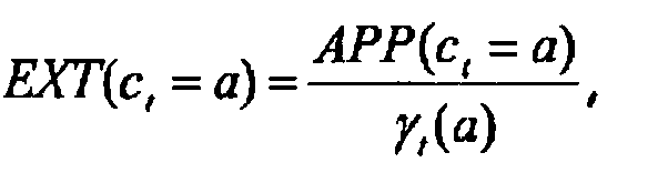
- The a posteriori probability APP(ct = a) = Pr(ct = a| y ) for each bit may be further used during to decoding process for generating/determining the best estimates of this received bit (either 0 or 1), based upon its received value and this a posteriori probability . This additional block is not shown in the figures .
- To improve the decoding performance from the point of view of accuracy, some embodiments of the method use an iterative process. In these embodiments the calculated value of the extrinsic information


- In one example the original parity set of 4 bits is going to be split into two partitions of 2 bits. For the first iteration, we can imagine that the first submatrixis composed of the two first rows of H and that the second submatrix
 represents the two last rows of H such as

- Hence, for the first iteration, the first subtrellis is based onand the second on


- For the second iteration, the first submatrixmay be composed of the first and the third rows of H , and the second submatrix
 of the complementary rows (the second and the fourth rows respectively) such as

- For the second iteration, the first subtrellis is thus constructed by usingand the second


- Finally, for the third iteration, the first and the last rows of H may be combined in the first submatrixand the remaining rows in
 such as

- Similarly to the two previous iterations, the first subtrellis for the last iteration is based onand the second on
 The resulting decoding scheme for the three iterations is depicted in
Fig. 6 . In this figure each decoding block corresponds to a device as depicted inFig. 5 , with the difference that only the first block in the chain uses the a priori incoming information, whereas successive blocks use the extrinsic information as further information. Another difference with the device ofFig. 5 is that only the last block in the chain gives the a posteriori probability. - One may notice that the extrinsic information at the output of a decoding block is used as a priori information in the next decoding block. Consequently, the iterative decoding performance relies on the improvement of a priori information through iterations. At the last iteration, the improved a posteriori probabilities are given at the output of the last decoding block.
- In this example, a simple situation has been considered to illustrate the principle. Indeed, two partitions of 2 bits have been studied, resulting in only three different iterations. In a more general scenario, long block codes are used and the number of iterations can be strongly increased due to a larger diversity in the partitioning design.
- The choice of the submatrices partitioning should anyhow be realized in order to increase the diversity. The number of iterations can be fixed or be optimized as well in order to optimize the criterion performance/complexity. For small parity matrices, all the combination can still be used in successive iteration steps.
- Compared to the prior art method the subject method, without iterations is already comparable from the point of view of accuracy as the method of
US patent 7243288 which uses two iterations. With 3 iterations, such as for example with the embodiment ofFig. 6 , accuracy is again increased. For having the same performance the prior art method would need 6 iterations, whereas the decoder ofFig. 6 only needs 3 iterations. - The method as described before for the BCJR algorithm can also be used for other algorithms such as the Max Log MAP algorithm. The Max Log MAP algorithm represents an optimized implementation of BCJR algorithm in order to circumvent problems with the numerical representation of very large or very small numbers and reduce decoding complexity.
- While the principles of the invention have been described above in connection with specific apparatus, it is to be clearly understood that this description is made only by way of example and not as a limitation on the scope of the invention, as defined in the appended claims.
Claims (9)
- Method for calculating an a posteriori probability for each incoming input bit of a sequence of incoming bits during decoding of a block code, said block code involving states related to a Trellis diagram, said method further including a step of decomposing the parity check matrix into a set of p submatrices, each submatrix being associated with one of p subtrellis diagrams of said Trellis diagram, said method further including the steps of, per subtrellis, and in parallel calculating auxiliary parameters related to the said a posteriori probability, and a step of combining said auxiliary parameters determined in parallel per subtrellis such as to provide the a posteriory probability parameter.
- Method according to claim 1 wherein an extrinsic information parameter is calculated during the combining step of said auxiliary parameters, and wherein said extrinsic information parameter is used as an input parameter during a succession of iterations of said method.
- Method according to claim 2 wherein in each iteration step the division of the parity check matrix into a set of submatrices is done in a different way.
- Method according to claim 2 or 3 wherein said a posteriori probability parameter is provided during the last iteration.
- Device for calculating an a posteriori probability parameter for decoding a block code, said apparatus receiving a sequence of incoming bit values, said apparatus including a computation unit for decomposing the parity check matrix associated to said block code into a set of p submatrices, each submatrix being associated with one of p subtrellis diagrams of said Trellis diagram associated to said block code, said apparatus further including a set of p processing units for per subtrellis, calculating further auxiliary parameters related to the said a posteriori probability, and a combining unit for combining said auxiliary parameters determined in parallel per subtrellis for providing an output parameter ( EXT) related to the a posteriori probability parameter.
- Device according to claim 5 wherein said output parameter is said a posteriori probability parameter.
- Apparatus including a sequence of devices according to claim 5 and wherein each output parameter of each device is used as an additional input parameter of the next device, and wherein the last device of the sequence is adapted to provide said a posteriori probability parameter.
- Apparatus according to claim 7 further including control means for controlling each computation block of each device such that for each device the division of the parity check matrix into a set of submatrices is done in a different way.
- Arrangement for decoding block codes, said arrangement includes a device or apparatus in accordance with any of the previous claims 5 to 8.
Priority Applications (1)
| Application Number | Priority Date | Filing Date | Title |
|---|---|---|---|
| EP09290070.3A EP2214322B1 (en) | 2009-01-30 | 2009-01-30 | Iterative MAP decoding of block codes using sub-trellises |
Applications Claiming Priority (1)
| Application Number | Priority Date | Filing Date | Title |
|---|---|---|---|
| EP09290070.3A EP2214322B1 (en) | 2009-01-30 | 2009-01-30 | Iterative MAP decoding of block codes using sub-trellises |
Publications (2)
| Publication Number | Publication Date |
|---|---|
| EP2214322A1 true EP2214322A1 (en) | 2010-08-04 |
| EP2214322B1 EP2214322B1 (en) | 2015-04-08 |
Family
ID=40630336
Family Applications (1)
| Application Number | Title | Priority Date | Filing Date |
|---|---|---|---|
| EP09290070.3A Active EP2214322B1 (en) | 2009-01-30 | 2009-01-30 | Iterative MAP decoding of block codes using sub-trellises |
Country Status (1)
| Country | Link |
|---|---|
| EP (1) | EP2214322B1 (en) |
Cited By (4)
| Publication number | Priority date | Publication date | Assignee | Title |
|---|---|---|---|---|
| WO2012175636A1 (en) * | 2011-06-22 | 2012-12-27 | Nxp B.V. | Two-dimensional iterative processing for dab receivers based on trellis-decomposition |
| WO2015107315A1 (en) * | 2014-01-17 | 2015-07-23 | Orange | Encoding and decoding linear code from lattices |
| WO2016198801A1 (en) * | 2015-06-11 | 2016-12-15 | Orange | Decoding based on a plurality of four-state lattices with self-complementary sections |
| CN110266322A (en) * | 2019-06-24 | 2019-09-20 | 上海航天测控通信研究所 | A kind of iterative decoding method of very high frequency(VHF) data exchange system |
Citations (1)
| Publication number | Priority date | Publication date | Assignee | Title |
|---|---|---|---|---|
| US7243288B1 (en) | 2000-06-24 | 2007-07-10 | Motorola Inc. | Method and apparatus for turbo decoding block codes |
-
2009
- 2009-01-30 EP EP09290070.3A patent/EP2214322B1/en active Active
Patent Citations (1)
| Publication number | Priority date | Publication date | Assignee | Title |
|---|---|---|---|---|
| US7243288B1 (en) | 2000-06-24 | 2007-07-10 | Motorola Inc. | Method and apparatus for turbo decoding block codes |
Non-Patent Citations (4)
| Title |
|---|
| HARI T MOORTHY ET AL: "Good Trellises for IC Implementation of Viterbi Decoders for Linear Block Codes", IEEE TRANSACTIONS ON COMMUNICATIONS, IEEE SERVICE CENTER, PISCATAWAY, NJ, US, vol. 45, no. 1, 1 January 1997 (1997-01-01), XP011008873, ISSN: 0090-6778 * |
| J. WOLF: "Efficient Maximum Likelihood Decoding of Linear Block Codes using a Trellis", IEEE TRANSACTIONS ON INFORMATION THEORY, vol. 24, January 1978 (1978-01-01), pages 76 - 80 |
| L. BAHL ET AL.: "Optimal Decoding of Linear Codes for Minimizing Symbol Error Rate", IEEE TRANSACTIONS ON INFORMATION THEORY, vol. 20, March 1974 (1974-03-01), pages 284 - 287 |
| YE LIU ET AL: "MAP Algorithms for Decoding Linear Block Codes Based on Sectionalized Trellis Diagrams", IEEE TRANSACTIONS ON COMMUNICATIONS, IEEE SERVICE CENTER, PISCATAWAY, NJ, US, vol. 48, no. 4, 1 April 2000 (2000-04-01), pages 577 - 587, XP011010820, ISSN: 0090-6778 * |
Cited By (7)
| Publication number | Priority date | Publication date | Assignee | Title |
|---|---|---|---|---|
| WO2012175636A1 (en) * | 2011-06-22 | 2012-12-27 | Nxp B.V. | Two-dimensional iterative processing for dab receivers based on trellis-decomposition |
| WO2015107315A1 (en) * | 2014-01-17 | 2015-07-23 | Orange | Encoding and decoding linear code from lattices |
| FR3016760A1 (en) * | 2014-01-17 | 2015-07-24 | Orange | METHOD AND DEVICE FOR DECODING SYMBOLS CODED USING A CORRECTING LINEAR ERROR CODE, METHOD AND DEVICE FOR ENCODING, AND CORRESPONDING COMPUTER PROGRAM |
| WO2016198801A1 (en) * | 2015-06-11 | 2016-12-15 | Orange | Decoding based on a plurality of four-state lattices with self-complementary sections |
| FR3037457A1 (en) * | 2015-06-11 | 2016-12-16 | Orange | CODING AND DECODING METHODS AND DEVICES BASED ON A SET OF LATTICE CONSTRUCTED WITH SELF-ADDITIONAL 4-STATE SECTIONS AND CORRESPONDING COMPUTER PROGRAMS |
| CN110266322A (en) * | 2019-06-24 | 2019-09-20 | 上海航天测控通信研究所 | A kind of iterative decoding method of very high frequency(VHF) data exchange system |
| CN110266322B (en) * | 2019-06-24 | 2023-02-07 | 上海航天测控通信研究所 | Iterative decoding method for very high frequency data exchange system |
Also Published As
| Publication number | Publication date |
|---|---|
| EP2214322B1 (en) | 2015-04-08 |
Similar Documents
| Publication | Publication Date | Title |
|---|---|---|
| US7539920B2 (en) | LDPC decoding apparatus and method with low computational complexity algorithm | |
| EP3659261B1 (en) | Turbo product code based on polar codes | |
| EP3577765B1 (en) | Soft output decoding of polar codes using successive cancelation list (scl) decoding | |
| US6715120B1 (en) | Turbo decoder with modified input for increased code word length and data rate | |
| KR100891782B1 (en) | Apparatus and method for forward error correction in high speed data transmission system | |
| CN108847848B (en) | A BP Decoding Algorithm for Polar Codes Based on Information Post-processing | |
| US8266493B1 (en) | Low-density parity check decoding using combined check node and variable node | |
| US8245116B2 (en) | Method for performing soft decision decoding of Euclidean space Reed-Muller codes | |
| US20050229087A1 (en) | Decoding apparatus for low-density parity-check codes using sequential decoding, and method thereof | |
| JP4227481B2 (en) | Decoding device and decoding method | |
| US20040243917A1 (en) | Apparatus and method for decoding a low density parity check code in a communication system | |
| US11082147B2 (en) | Processing method, device and system for overlap multiplexing system | |
| EP3602794B1 (en) | Check bit concatenated polar codes | |
| EP2833553B1 (en) | LDPC decoder | |
| KR101583139B1 (en) | High-Throughput Low-Complexity Successive-Cancellation Polar Decoder Architecture and Method | |
| JP4651600B2 (en) | Check Node Update Method in Low Density Parity Check Decoder | |
| CN110166171A (en) | Multielement LDPC code compensates high-performance decoding scheme based on the segmented of EMS | |
| EP2214322B1 (en) | Iterative MAP decoding of block codes using sub-trellises | |
| US12587312B2 (en) | Hybrid product polar codes-based communication systems and methods | |
| US9800437B2 (en) | Parallelizable reduced state sequence estimation via BCJR algorithm | |
| US8983008B2 (en) | Methods and apparatus for tail termination of turbo decoding | |
| US7266757B1 (en) | Pipelined architecture implementing recursion processes for forward error correction | |
| KR20090012189A (en) | Decoding Apparatus and Method Using Scaling-based Improved MINI-SMW Iterative Decoding Algorithm for Performance Improvement of LDPC Code | |
| US7178090B2 (en) | Error correction code decoding device | |
| KR20140092834A (en) | Error corrector coding and decoding |
Legal Events
| Date | Code | Title | Description |
|---|---|---|---|
| PUAI | Public reference made under article 153(3) epc to a published international application that has entered the european phase |
Free format text: ORIGINAL CODE: 0009012 |
|
| AK | Designated contracting states |
Kind code of ref document: A1 Designated state(s): AT BE BG CH CY CZ DE DK EE ES FI FR GB GR HR HU IE IS IT LI LT LU LV MC MK MT NL NO PL PT RO SE SI SK TR |
|
| AX | Request for extension of the european patent |
Extension state: AL BA RS |
|
| 17P | Request for examination filed |
Effective date: 20110204 |
|
| AKX | Designation fees paid |
Designated state(s): AT BE BG CH CY CZ DE DK EE ES FI FR GB GR HR HU IE IS IT LI LT LU LV MC MK MT NL NO PL PT RO SE SI SK TR |
|
| RAP1 | Party data changed (applicant data changed or rights of an application transferred) |
Owner name: CENTRE NATIONAL DE LA RECHERCHE SCIENTIFIQUE Owner name: ALCATEL LUCENT Owner name: SUPELEC |
|
| 17Q | First examination report despatched |
Effective date: 20140313 |
|
| RAP1 | Party data changed (applicant data changed or rights of an application transferred) |
Owner name: ALCATEL LUCENT Owner name: SUPELEC Owner name: CENTRE NATIONAL DE LA RECHERCHE SCIENTIFIQUE |
|
| GRAP | Despatch of communication of intention to grant a patent |
Free format text: ORIGINAL CODE: EPIDOSNIGR1 |
|
| INTG | Intention to grant announced |
Effective date: 20141106 |
|
| GRAS | Grant fee paid |
Free format text: ORIGINAL CODE: EPIDOSNIGR3 |
|
| GRAA | (expected) grant |
Free format text: ORIGINAL CODE: 0009210 |
|
| AK | Designated contracting states |
Kind code of ref document: B1 Designated state(s): AT BE BG CH CY CZ DE DK EE ES FI FR GB GR HR HU IE IS IT LI LT LU LV MC MK MT NL NO PL PT RO SE SI SK TR |
|
| REG | Reference to a national code |
Ref country code: GB Ref legal event code: FG4D |
|
| RIN1 | Information on inventor provided before grant (corrected) |
Inventor name: KUMAR, VINOD Inventor name: DUHAMEL, PIERRE Inventor name: KIEFFER, MICHEL Inventor name: MARIN, CEDRIC Inventor name: SAYADI, BESSEM |
|
| REG | Reference to a national code |
Ref country code: CH Ref legal event code: EP |
|
| REG | Reference to a national code |
Ref country code: IE Ref legal event code: FG4D |
|
| REG | Reference to a national code |
Ref country code: AT Ref legal event code: REF Ref document number: 721231 Country of ref document: AT Kind code of ref document: T Effective date: 20150515 |
|
| REG | Reference to a national code |
Ref country code: DE Ref legal event code: R096 Ref document number: 602009030455 Country of ref document: DE Effective date: 20150521 |
|
| REG | Reference to a national code |
Ref country code: AT Ref legal event code: MK05 Ref document number: 721231 Country of ref document: AT Kind code of ref document: T Effective date: 20150408 |
|
| REG | Reference to a national code |
Ref country code: NL Ref legal event code: VDEP Effective date: 20150408 |
|
| REG | Reference to a national code |
Ref country code: LT Ref legal event code: MG4D |
|
| PG25 | Lapsed in a contracting state [announced via postgrant information from national office to epo] |
Ref country code: NL Free format text: LAPSE BECAUSE OF FAILURE TO SUBMIT A TRANSLATION OF THE DESCRIPTION OR TO PAY THE FEE WITHIN THE PRESCRIBED TIME-LIMIT Effective date: 20150408 |
|
| PG25 | Lapsed in a contracting state [announced via postgrant information from national office to epo] |
Ref country code: NO Free format text: LAPSE BECAUSE OF FAILURE TO SUBMIT A TRANSLATION OF THE DESCRIPTION OR TO PAY THE FEE WITHIN THE PRESCRIBED TIME-LIMIT Effective date: 20150708 Ref country code: HR Free format text: LAPSE BECAUSE OF FAILURE TO SUBMIT A TRANSLATION OF THE DESCRIPTION OR TO PAY THE FEE WITHIN THE PRESCRIBED TIME-LIMIT Effective date: 20150408 Ref country code: LT Free format text: LAPSE BECAUSE OF FAILURE TO SUBMIT A TRANSLATION OF THE DESCRIPTION OR TO PAY THE FEE WITHIN THE PRESCRIBED TIME-LIMIT Effective date: 20150408 Ref country code: FI Free format text: LAPSE BECAUSE OF FAILURE TO SUBMIT A TRANSLATION OF THE DESCRIPTION OR TO PAY THE FEE WITHIN THE PRESCRIBED TIME-LIMIT Effective date: 20150408 Ref country code: PT Free format text: LAPSE BECAUSE OF FAILURE TO SUBMIT A TRANSLATION OF THE DESCRIPTION OR TO PAY THE FEE WITHIN THE PRESCRIBED TIME-LIMIT Effective date: 20150810 Ref country code: ES Free format text: LAPSE BECAUSE OF FAILURE TO SUBMIT A TRANSLATION OF THE DESCRIPTION OR TO PAY THE FEE WITHIN THE PRESCRIBED TIME-LIMIT Effective date: 20150408 |
|
| PG25 | Lapsed in a contracting state [announced via postgrant information from national office to epo] |
Ref country code: AT Free format text: LAPSE BECAUSE OF FAILURE TO SUBMIT A TRANSLATION OF THE DESCRIPTION OR TO PAY THE FEE WITHIN THE PRESCRIBED TIME-LIMIT Effective date: 20150408 Ref country code: IS Free format text: LAPSE BECAUSE OF FAILURE TO SUBMIT A TRANSLATION OF THE DESCRIPTION OR TO PAY THE FEE WITHIN THE PRESCRIBED TIME-LIMIT Effective date: 20150808 Ref country code: LV Free format text: LAPSE BECAUSE OF FAILURE TO SUBMIT A TRANSLATION OF THE DESCRIPTION OR TO PAY THE FEE WITHIN THE PRESCRIBED TIME-LIMIT Effective date: 20150408 Ref country code: GR Free format text: LAPSE BECAUSE OF FAILURE TO SUBMIT A TRANSLATION OF THE DESCRIPTION OR TO PAY THE FEE WITHIN THE PRESCRIBED TIME-LIMIT Effective date: 20150709 |
|
| REG | Reference to a national code |
Ref country code: DE Ref legal event code: R097 Ref document number: 602009030455 Country of ref document: DE |
|
| REG | Reference to a national code |
Ref country code: FR Ref legal event code: PLFP Year of fee payment: 8 |
|
| PG25 | Lapsed in a contracting state [announced via postgrant information from national office to epo] |
Ref country code: DK Free format text: LAPSE BECAUSE OF FAILURE TO SUBMIT A TRANSLATION OF THE DESCRIPTION OR TO PAY THE FEE WITHIN THE PRESCRIBED TIME-LIMIT Effective date: 20150408 Ref country code: EE Free format text: LAPSE BECAUSE OF FAILURE TO SUBMIT A TRANSLATION OF THE DESCRIPTION OR TO PAY THE FEE WITHIN THE PRESCRIBED TIME-LIMIT Effective date: 20150408 |
|
| PLBE | No opposition filed within time limit |
Free format text: ORIGINAL CODE: 0009261 |
|
| STAA | Information on the status of an ep patent application or granted ep patent |
Free format text: STATUS: NO OPPOSITION FILED WITHIN TIME LIMIT |
|
| PG25 | Lapsed in a contracting state [announced via postgrant information from national office to epo] |
Ref country code: RO Free format text: LAPSE BECAUSE OF NON-PAYMENT OF DUE FEES Effective date: 20150408 Ref country code: CZ Free format text: LAPSE BECAUSE OF FAILURE TO SUBMIT A TRANSLATION OF THE DESCRIPTION OR TO PAY THE FEE WITHIN THE PRESCRIBED TIME-LIMIT Effective date: 20150408 Ref country code: PL Free format text: LAPSE BECAUSE OF FAILURE TO SUBMIT A TRANSLATION OF THE DESCRIPTION OR TO PAY THE FEE WITHIN THE PRESCRIBED TIME-LIMIT Effective date: 20150408 Ref country code: SK Free format text: LAPSE BECAUSE OF FAILURE TO SUBMIT A TRANSLATION OF THE DESCRIPTION OR TO PAY THE FEE WITHIN THE PRESCRIBED TIME-LIMIT Effective date: 20150408 |
|
| 26N | No opposition filed |
Effective date: 20160111 |
|
| PG25 | Lapsed in a contracting state [announced via postgrant information from national office to epo] |
Ref country code: IT Free format text: LAPSE BECAUSE OF FAILURE TO SUBMIT A TRANSLATION OF THE DESCRIPTION OR TO PAY THE FEE WITHIN THE PRESCRIBED TIME-LIMIT Effective date: 20150408 |
|
| PG25 | Lapsed in a contracting state [announced via postgrant information from national office to epo] |
Ref country code: BE Free format text: LAPSE BECAUSE OF NON-PAYMENT OF DUE FEES Effective date: 20160131 Ref country code: SI Free format text: LAPSE BECAUSE OF FAILURE TO SUBMIT A TRANSLATION OF THE DESCRIPTION OR TO PAY THE FEE WITHIN THE PRESCRIBED TIME-LIMIT Effective date: 20150408 |
|
| PG25 | Lapsed in a contracting state [announced via postgrant information from national office to epo] |
Ref country code: BE Free format text: LAPSE BECAUSE OF FAILURE TO SUBMIT A TRANSLATION OF THE DESCRIPTION OR TO PAY THE FEE WITHIN THE PRESCRIBED TIME-LIMIT Effective date: 20150408 Ref country code: LU Free format text: LAPSE BECAUSE OF FAILURE TO SUBMIT A TRANSLATION OF THE DESCRIPTION OR TO PAY THE FEE WITHIN THE PRESCRIBED TIME-LIMIT Effective date: 20160130 |
|
| REG | Reference to a national code |
Ref country code: CH Ref legal event code: PL |
|
| PG25 | Lapsed in a contracting state [announced via postgrant information from national office to epo] |
Ref country code: MC Free format text: LAPSE BECAUSE OF FAILURE TO SUBMIT A TRANSLATION OF THE DESCRIPTION OR TO PAY THE FEE WITHIN THE PRESCRIBED TIME-LIMIT Effective date: 20150408 |
|
| PG25 | Lapsed in a contracting state [announced via postgrant information from national office to epo] |
Ref country code: CH Free format text: LAPSE BECAUSE OF NON-PAYMENT OF DUE FEES Effective date: 20160131 Ref country code: LI Free format text: LAPSE BECAUSE OF NON-PAYMENT OF DUE FEES Effective date: 20160131 |
|
| REG | Reference to a national code |
Ref country code: IE Ref legal event code: MM4A |
|
| REG | Reference to a national code |
Ref country code: FR Ref legal event code: PLFP Year of fee payment: 9 |
|
| PG25 | Lapsed in a contracting state [announced via postgrant information from national office to epo] |
Ref country code: IE Free format text: LAPSE BECAUSE OF NON-PAYMENT OF DUE FEES Effective date: 20160130 |
|
| PG25 | Lapsed in a contracting state [announced via postgrant information from national office to epo] |
Ref country code: SE Free format text: LAPSE BECAUSE OF FAILURE TO SUBMIT A TRANSLATION OF THE DESCRIPTION OR TO PAY THE FEE WITHIN THE PRESCRIBED TIME-LIMIT Effective date: 20150408 |
|
| PG25 | Lapsed in a contracting state [announced via postgrant information from national office to epo] |
Ref country code: MT Free format text: LAPSE BECAUSE OF FAILURE TO SUBMIT A TRANSLATION OF THE DESCRIPTION OR TO PAY THE FEE WITHIN THE PRESCRIBED TIME-LIMIT Effective date: 20150408 |
|
| REG | Reference to a national code |
Ref country code: FR Ref legal event code: PLFP Year of fee payment: 10 |
|
| PG25 | Lapsed in a contracting state [announced via postgrant information from national office to epo] |
Ref country code: HU Free format text: LAPSE BECAUSE OF FAILURE TO SUBMIT A TRANSLATION OF THE DESCRIPTION OR TO PAY THE FEE WITHIN THE PRESCRIBED TIME-LIMIT; INVALID AB INITIO Effective date: 20090130 Ref country code: CY Free format text: LAPSE BECAUSE OF FAILURE TO SUBMIT A TRANSLATION OF THE DESCRIPTION OR TO PAY THE FEE WITHIN THE PRESCRIBED TIME-LIMIT Effective date: 20150408 |
|
| PG25 | Lapsed in a contracting state [announced via postgrant information from national office to epo] |
Ref country code: MK Free format text: LAPSE BECAUSE OF FAILURE TO SUBMIT A TRANSLATION OF THE DESCRIPTION OR TO PAY THE FEE WITHIN THE PRESCRIBED TIME-LIMIT Effective date: 20150408 Ref country code: TR Free format text: LAPSE BECAUSE OF FAILURE TO SUBMIT A TRANSLATION OF THE DESCRIPTION OR TO PAY THE FEE WITHIN THE PRESCRIBED TIME-LIMIT Effective date: 20150408 Ref country code: MT Free format text: LAPSE BECAUSE OF FAILURE TO SUBMIT A TRANSLATION OF THE DESCRIPTION OR TO PAY THE FEE WITHIN THE PRESCRIBED TIME-LIMIT Effective date: 20160131 |
|
| PG25 | Lapsed in a contracting state [announced via postgrant information from national office to epo] |
Ref country code: BG Free format text: LAPSE BECAUSE OF FAILURE TO SUBMIT A TRANSLATION OF THE DESCRIPTION OR TO PAY THE FEE WITHIN THE PRESCRIBED TIME-LIMIT Effective date: 20150408 |
|
| PGFP | Annual fee paid to national office [announced via postgrant information from national office to epo] |
Ref country code: GB Payment date: 20251211 Year of fee payment: 18 |
|
| PGFP | Annual fee paid to national office [announced via postgrant information from national office to epo] |
Ref country code: FR Payment date: 20251208 Year of fee payment: 18 |
|
| PGFP | Annual fee paid to national office [announced via postgrant information from national office to epo] |
Ref country code: DE Payment date: 20251203 Year of fee payment: 18 |