EP2214068A1 - Automation system with a programmable matrix module - Google Patents
Automation system with a programmable matrix module Download PDFInfo
- Publication number
- EP2214068A1 EP2214068A1 EP10150296A EP10150296A EP2214068A1 EP 2214068 A1 EP2214068 A1 EP 2214068A1 EP 10150296 A EP10150296 A EP 10150296A EP 10150296 A EP10150296 A EP 10150296A EP 2214068 A1 EP2214068 A1 EP 2214068A1
- Authority
- EP
- European Patent Office
- Prior art keywords
- module
- processing unit
- modules
- automation system
- terminal
- Prior art date
- Legal status (The legal status is an assumption and is not a legal conclusion. Google has not performed a legal analysis and makes no representation as to the accuracy of the status listed.)
- Ceased
Links
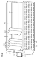
Images

Classifications
-
- G—PHYSICS
- G05—CONTROLLING; REGULATING
- G05B—CONTROL OR REGULATING SYSTEMS IN GENERAL; FUNCTIONAL ELEMENTS OF SUCH SYSTEMS; MONITORING OR TESTING ARRANGEMENTS FOR SUCH SYSTEMS OR ELEMENTS
- G05B19/00—Programme-control systems
- G05B19/02—Programme-control systems electric
- G05B19/04—Programme control other than numerical control, i.e. in sequence controllers or logic controllers
- G05B19/05—Programmable logic controllers, e.g. simulating logic interconnections of signals according to ladder diagrams or function charts
- G05B19/054—Input/output
Abstract
Description
Automatisierungsgeräte weisen in der Regel eine Vielzahl von Eingangs- und/oder Ausgangsmodulen auf (EM), welche abgekürzt auch als I/O-Module bezeichnet werden. Hierüber kann eine elektronische Verarbeitungseinheit im Automatisierungsgerät, meist ein programmgesteuerter Prozessor, bevorzugt Messsignale von einem technischen Prozess bzw. einer Anlage entgegennehmen und Stellsignale bzw. Steuerbefehle an Betriebsmittel des technischen Prozesses ausgeben. Zum Anschluss der I/O-Module an diese technischen Betriebsmittel, z.B. an Sensoren und Aktoren, meist über Prozessverkabelungen und Feldbusse sind eine Vielzahl von Klemmen vorhanden, welche z.B. in Klemmenbereichen zusammenfasst werden können.Automation devices generally have a plurality of input and / or output modules (EM), which are also abbreviated as I / O modules. An electronic processing unit in the automation device, usually a program-controlled processor, can preferably receive measurement signals from a technical process or a system and output control signals or control commands to operating means of the technical process. To connect the I / O modules to these technical resources, e.g. On sensors and actuators, mostly via process cabling and field buses, there are a multiplicity of terminals, which may be e.g. can be summarized in terminal areas.
Automatisierungsgeräte sind in der Regel so aufgebaut, dass eine direkte Kopplung, d.h. eine Art lineare Verbindung, von der elektronischen Verarbeitungseinheit über die I/O-Module direkt zu einem Klemmenbereich besteht. Dabei ist jedem I/O-Modul eine definierte Klemme starr zugeordnet, also mit dieser fest verdrahtet und somit funktionsmäßig linear verbunden. In einem Automatisierungsgerät sind somit die Reihenfolge, Zuordnung und Position zwischen jeder einzelnen Klemme und jedem einzelnen I/O-Modul definiert und starr festgelegt. Dies hat zur Folge, dass ein Wechsel bzw. eine freie, wahlweise Zuordnung zwischen einem I/O-Modul und einer Klemme bzw. eine Erweiterung in einer montierten Anlage nicht ohne aufwendiges Abklemmen, Umklemmen oder Umbauen möglich ist. Bei Vorliegen von eingeschränkten Platzverhältnissen können im Einzelfall derartige Umrangierungen auch unmöglich sein.Automation devices are typically constructed so that direct coupling, i. a kind of linear connection from the electronic processing unit via the I / O modules directly to a terminal area. Each I / O module is rigidly assigned to a defined terminal, ie hard-wired to it and thus functionally connected linearly. In an automation device, the order, assignment and position between each individual terminal and each individual I / O module are thus defined and fixed. This has the consequence that a change or a free, optional assignment between an I / O module and a terminal or an extension in a mounted system is not possible without costly disconnecting, reconnecting or rebuilding. In the case of limited space available in such a case, such Umrangierungen may also be impossible.
In
Der Erfindung liegt die Aufgabe zu Grunde, ein zur Führung eines technischen Prozesses dienendes Automatisierungssystem der oben angegebenen Art derart weiter auszubilden, dass die vorhandenen I/O-Module optimal genutzt werden können.The invention is based on the object of further developing an automation system of the type specified above for guiding a technical process in such a way that the existing I / O modules can be optimally utilized.
Die Aufgabe wird mit einem Automatisierungssystem gemäß Anspruch 1 gelöst.The object is achieved with an automation system according to
Dieses weist eine elektronische Verarbeitungseinheit, I/O-Module zur Ein- und/oder Ausgabe von Prozesssignalen an Betriebsmittel des technischen Prozesses, insbesondere an Sensoren und Aktoren, und Klemmenbausteine zum Anschluss der Betriebsmittel der Anlage an die I/O-Module auf, weiterhin ist ein programmierbares Matrixmodul vorhanden, womit von der Verarbeitungseinheit einem oder mehreren Klemmenbausteinen dynamisch ein oder mehrere I/O-Module verschaltungstechnisch zugeordnet werden können. Die Verarbeitungseinheit ist vorteilhaft derart ausgestaltet, dass einem I/O-Modul mit Hilfe des programmierbaren Matrixmoduls zeitgesteuert mehrere Klemmenbausteine verschaltungstechnisch zugeordnet werden können, wobei je einem Klemmenbaustein je ein Zeitschlitz zugeordnet wird. Mit dieser Ausgestaltung ergibt sich eine freie, programmgesteuerte Zuordnung der I/O-Module zu den Klemmenbausteinen. Die Verarbeitungseinheit könnte beispielsweise in einem Hardwarepool, welcher aus einer Anzahl von I/O-Modulen bestehen kann, nachfragen welche Hardware sich momentan im Leerlauf befindet, und diese dann mit neuen Aufgaben betreuen, wobei das erforderliche I/O-Modul an die Klemmenbausteine geschaltet wird. Vorteilhaft ist somit möglich, dass beispielsweise ein einziges I/O-Modul die Prozesssignale mehrerer Betriebsmittel an den jeweiligen Klemmenbausteinen beispielsweise in einer zeitlichen Reihenfolge gestaffelt abfragt bzw. suksessive an dieser ausgibt.This has an electronic processing unit, I / O modules for input and / or output of process signals to resources of the technical process, in particular to sensors and actuators, and terminal blocks for connecting the equipment of the system to the I / O modules, continue a programmable matrix module is provided, which can be assigned by the processing unit one or more terminal blocks dynamically one or more I / O modules interconnection technology. The processing unit is advantageously designed such that an I / O module with the aid of the programmable matrix module time-controlled multiple terminal blocks can be assigned circuitry, each one terminal block is assigned a time slot. This configuration results in a free, program-controlled assignment of the I / O modules to the terminal blocks. The processing unit could, for example, in a hardware pool, which may consist of a number of I / O modules, ask what hardware is currently idle, and then look after them with new tasks, with the required I / O module connected to the terminal blocks becomes. It is thus advantageously possible that, for example, a single I / O module, the process signals of several Scans resources on the respective terminal blocks, for example, in a temporal order staggered or suksessive outputs to this.
In einer vorteilhaften Ausgestaltung weist das Automatisierungssystem in dem Matrixmodul einen Multiplexer auf. Der Multiplexer ist dabei vorzugsweise als ein Selektionsschaltnetzwerk ausgestaltet, wobei bei einem zyklischen Durchlauf der Multiplexers in unterschiedlichen Zeitschlitzen quasi parallele Datenströme in serielle Datenströme umgewandelt. Die unterschiedlichen Klemmbausteine werden also demnach zeitlich hintereinander gestafelt abgetastet und ihre Ein- bzw. Ausgabewerte über das eine I/O-Modul weiter an die Verarbeitungseinheit gegeben. Als besonderer Vorteil ist hier zu nennen, dass sich mit dieser Ausgestaltung eine Automatisierungsaufgabe lösen lässt, bei welcher zuvor mehrere I/O-Module notwendig waren, und nun dieselbe Automatisierungsaufgabe mit einem einzigen I/O-Modul gelöst werden kann. Damit ergibt sich ein Kostenvorteil und ein Baugrößenvorteil des Automatisierungsgerätes, da auf komplette Baugruppen bzw. zusätzliche I/O-Module verzichtet werden kann.In an advantageous embodiment, the automation system in the matrix module on a multiplexer. The multiplexer is preferably designed as a selection switching network, wherein in a cyclic passage of the multiplexer in different time slots quasi-parallel data streams converted into serial data streams. Accordingly, the different terminal blocks are scanned in temporal succession and their input or output values are passed on to the processing unit via the one I / O module. A particular advantage here is that can be solved with this embodiment, an automation task in which previously several I / O modules were necessary, and now the same automation task can be solved with a single I / O module. This results in a cost advantage and a size advantage of the automation device, since it is possible to dispense with complete modules or additional I / O modules.
Eine weitere Ausgestaltungsmöglichkeit für das Automatisierungssystem um die Flexibilität zu erhöhen ergibt sich, wenn die Verarbeitungseinheit weiterhin ausgestaltet ist, dass das I/O-Modul über einen Koppelbus zu aktivieren ist.Another design option for the automation system to increase the flexibility results when the processing unit is further configured that the I / O module is to be activated via a coupling bus.
Dieses ermöglicht anwendungsabhängig eine dynamische, programmtechnische Rangierung der von den Betriebsmitteln eines technischen Prozesses empfangenen Prozesssignale bzw. der von der Verarbeitungseinheit ermittelten und an die Betriebsmittel ausgegebenen Prozesssignale. Das programmierbare Matrixmodul funktioniert in der Art einer frei programmierbaren Vermittlung, womit jedes I/O-Modul mit jedem Klemmenbaustein verbunden werden kann. Diese verschaltungstechnische Zuordnung kann z.B. bei der Konfiguration des Automatisierungssystems an einer technischen Anlage angelegt bzw. auch im laufenden Betrieb flexibel aktualisiert werden. Die technischen Betriebsmittel einer Anlage, besondere im Feld verteilte Sensoren und Aktoren, können somit während einer Inbetriebnahme z.B. unter Berücksichtigung eines minimalen Kabel- und Rangieraufwandes an gut zugänglichen Klemmenbausteinen angeschlossen werden. Auch die I/O-Module können uneingeschränkt angeordnet werden, z.B. unter Berücksichtigung der Topologie der jeweiligen Anlage. Damit kann die Gefahr von Bestück- und Verdrahtungsfehlern, z.B. Verwechslungen bei der Zuordnung von I/O-Modulen und Klemmenbaustein, minimiert werden.Depending on the application, this enables dynamic, program-technical routing of the process signals received from the resources of a technical process or the process signals determined by the processing unit and output to the resources. The programmable matrix module operates in the manner of a freely programmable exchange, with which each I / O module can be connected to each terminal block. This interconnection assignment can be created, for example, in the configuration of the automation system to a technical system or even flexibly updated during operation. The technical Equipment of a system, special distributed in the field sensors and actuators can thus be connected during commissioning, for example, taking into account a minimum cable and maneuvering effort on easily accessible terminal blocks. The I / O modules can also be arranged without restrictions, eg taking into account the topology of the respective system. This minimizes the risk of assembly and wiring errors, eg confusion in the assignment of I / O modules and terminal block.
Vorteilhafte weitere Ausführungen der Erfindung sind in den Unteransprüchen angegeben. Die Erfindung wird nachfolgend an Hand der nachfolgend kurz angeführten Figuren näher erläutert. Dabei zeigt
- Fig. 1
- das Blockschaltbild eines Automatisierungssystems, welches gemäß der Erfindung mit einem zusätzlichen programmierbaren Matrixmodul zur Rangierung von Prozesssignalen ausgerüstet ist, und
- Fig. 2
- einen beispielhaften Aufbau eines Schnittstellen- bausteins in einem Automatisierungsgerät, welcher einen Klemmenbereich, eine Vielzahl von I/O-Modulen und ein programmierbares Matrixmodul für Prozess- signale gemäß der Erfindung aufweist.
- Fig. 1
- the block diagram of an automation system, which is equipped according to the invention with an additional programmable matrix module for routing of process signals, and
- Fig. 2
- an exemplary structure of an interface module in an automation device, which has a terminal area, a plurality of I / O modules and a programmable matrix module for process signals according to the invention.
Zwischen der elektronischen Verarbeitungseinheit 1 und der Prozessschnittstelle 42 sind im Beispiel der
Diese Signale am Ausgang eines jeden I/O Moduls sind entweder für ein oder mehrere Betriebsmittel des technischen Prozesses bestimmt, oder werden von einem oder mehreren Betriebsmitteln bereitgestellt. Es ist somit notwendig, die Ausgänge der I/O-Module im Aufnahmemodul 2 den zu den jeweiligen Betriebsmitteln führenden Kabelverbindungen des technischen Prozesses zuzuordnen. Diese Kabelverbindungen sind im Beispiel der
Gemäß der
Wird z.B. der Verarbeitungseinheit der Ausfall eines I/O-Moduls programmtechnisch gemeldet, so kann diese dem zugeordneten Klemmenbaustein, der auf Grund des Ausfalls keine Prozesssignale mehr empfangen oder an die Verarbeitungseinheit 1 übertragen kann, mit Hilfe des programmierbaren Matrixmoduls dynamisch ein anderes I/O-Modul verschaltungstechnisch zuordnen. Auf diese Weise kann der Weiterbetrieb des Automatisierungssystems ermöglicht werden. So können z.B. im Rahmen einer redundanten Anlageninstrumentierung mehr I/O-Module im Aufnahmemodul 2 gesteckt sein, als für einen normalen Betrieb benötigt werden. In diesem Falle würde die Verarbeitungseinheit den betroffenen Klemmenbaustein dynamisch einem bislang nicht genutzten I/O-Modul verschaltungstechnisch zuordnen.If, for example, the failure of an I / O module is reported programmatically to the processing unit, it can dynamically change the assigned terminal block, which can no longer receive or transfer process signals to the
Je nach Ausführung des Automatisierungssystems kann es möglich sein, dass die Verarbeitungseinheit auch den Ausfall eines Betriebsmittels des technischen Prozesses, z.B. eines Sensors oder Aktors, detektieren kann. In einem solchen Fall ist es mit der Erfindung möglich, dass die Verarbeitungseinheit dem betroffenen I/O-Modul, welches auf Grund des Ausfalls keine Prozesssignale mehr an den technischen Prozess übergeben oder von diesem entgegen nehmen kann, mit Hilfe des programmierbaren Matrixmoduls dynamisch einen anderen Klemmenbaustein verschaltungstechnisch zuordnet. Ist dieser mit zumindest eingeschränkt funktionsfähigen Betriebsmitteln der Anlage verbunden, so kann u.U unter Verwendung von Ersatzprozesssignalen deren Betrieb aufrechterhalten oder zumindest eine geordnete Stilllegung herbeigeführt werden. Ist im Rahmen eines Redundanzkonzepts der technische Prozess mit Reservebetriebsmitteln ausgestattet, z.B. mit Ersatzpumpen oder Notantrieben, so wird vorteilhaft dann von der Verarbeitungseinheit dem betroffenen I/O Modul dynamisch ein Klemmenbaustein verschaltungstechnisch zuordnet, an dem ein redundantes Betriebsmittel des technischen Anlage angeschlossen ist.Depending on the design of the automation system, it may be possible for the processing unit to also detect the failure of a resource of the technical process, e.g. a sensor or actuator can detect. In such a case, it is possible with the invention that the processing unit dynamically changes the affected I / O module, which can no longer transfer process signals to or from the technical process due to the failure, with the aid of the programmable matrix module Assigning the terminal block in terms of circuitry. If this is connected to at least partially functional equipment of the plant, it may be possible to maintain its operation or at least to effect orderly decommissioning using substitute process signals. If, in the context of a redundancy concept, the technical process is equipped with reserve resources, e.g. with replacement pumps or emergency drives, it is advantageous then the processing unit to the affected I / O module dynamically assigns a terminal block interconnected to which a redundant equipment of the technical system is connected.
Die Erfindung ermöglicht es sogar, dass die Verarbeitungseinheit einem I/O-Modul mit Hilfe des programmierbaren Matrixmoduls u.U. dynamisch mehrere Klemmenbausteine verschaltungstechnisch zuordnet. In diesem Falle aktiviert das I/O-Modul diese Klemmenbausteine, insbesondere zur Ein- und Ausgabe von Prozesssignalen, vorteilhaft zyklisch. Ein solcher Fall kann in der Praxis besonders dann auftreten, wenn an Klemmenbausteinen Betriebsmittel des technischen Prozesses angeschlossen sind, deren Zustände im Vergleich zur Verarbeitungsgeschwindigkeit des I/O-Moduls nur langsam veränderlich sind. Betriebsmittel dieser Art können z.B. Heizungen und die daran angeschlossenen Temperaturmessgeber sein. Es ist dann möglich, dass ein einziges I/O-Modul die Prozesssignale mehrerer Betriebsmittel an den jeweiligen Klemmbausteinen z.B. in einer zeitlichen Reihenfolge gestaffelt abfragt bzw. sukzessive an diese ausgibt. Das Matrixmodul weist dann zusätzlich die Funktion eines Multiplexers auf.The invention even makes it possible for the processing unit to dynamically allocate several terminal blocks dynamically to an I / O module with the aid of the programmable matrix module. In this case, the I / O module activates these terminal blocks, in particular for the input and output of process signals, advantageously cyclically. Such a case can occur in practice, in particular, when terminals of the technical process are connected to terminal blocks whose states are only slowly variable compared to the processing speed of the I / O module. Equipment of this kind can eg heaters and the be connected temperature transmitter. It is then possible that a single I / O module interrogates the process signals of several resources staggered at the respective terminal blocks, for example in a temporal order, or outputs them successively to them. The matrix module then additionally has the function of a multiplexer.
Andererseits ist es mit der Erfindung auch möglich, dass die Verarbeitungseinheit mit Hilfe des programmierbaren Matrixmoduls mehreren I/O-Modulen dynamisch einen einzigen Klemmenbaustein verschaltungstechnisch zuordnet. Auch in diesem Falle aktivieren die I/O-Module diesen Klemmenbaustein, insbesondere zur Ein- und Ausgabe von Prozesssignalen, zyklisch. Ein solcher Fall kann in der Praxis besonders dann auftreten, wenn an einem Klemmenbaustein ein Betriebsmittel des technischen Prozesses angeschlossen ist, dessen Zustand im Vergleich zur Verarbeitungsgeschwindigkeit der eingesetzten I/O-Module schnell veränderlich ist. Ein Betriebsmittel dieser Art kann z.B. ein drehzahlgeregelter Antrieb und ein daran angeschlossener Drehzahlmessgeber sein. Es ist dann möglich, dass mehrere I/O-Module das schnell veränderliche Prozesssignal des einzigen Betriebsmittels von dem jeweiligen Klemmbaustein z.B. in einer zeitlichen Reihenfolge mittels eines Zeitschlitzverfahrens abfragen bzw. an dieses ausgeben. Auch in diesem Falle weist das Matrixmodul dann zusätzlich die Funktion eines Multiplexers auf.On the other hand, it is also possible with the invention that the processing unit dynamically assigns a single terminal block to a plurality of I / O modules using the programmable matrix module. Also in this case, the I / O modules activate this terminal block, in particular for input and output of process signals, cyclically. Such a case can occur in practice especially when a device of the technical process is connected to a terminal block, the state of which is rapidly variable compared to the processing speed of the I / O modules used. A resource of this kind may e.g. be a variable speed drive and an attached speed encoder. It is then possible for a plurality of I / O modules to receive the fast variable process signal of the single resource from the respective terminal block, e.g. in a temporal order by means of a time slot method query or output to this. Also in this case, the matrix module then additionally has the function of a multiplexer.
Bei einer vorteilhaften, weiteren Ausführungsform detektiert die Verarbeitungseinheit, insbesondere bei der Inbetriebnahme, dynamisch in einem ersten Suchlauf die vorhandenen I/O-Module und in einem zweiten Suchlauf die an den Klemmenbausteinen angeschlossenen Betriebsmittel des technischen Prozesses. Vorzugsweise werden dabei die I/O-Module und Betriebsmittel nach Typ und Steckplatz detektiert. Damit sind quasi die aktivierbaren Zeilen und Spalten im programmierbaren Matrixmodul ermittelt. Die Verarbeitungseinheit kann nun dynamisch die verschaltungstechnische Zuordnung von einem oder mehreren Klemmenbausteinen mit einem oder mehreren I/O-Modulen insbesondere abhängig von einem anwendungsabhängigen Steuerungsprogramm automatisch vornehmen. Die Verarbeitungseinheit kann diesen Suchlauf bevorzugt bei einer Erstinbetriebnahme, aber auch zu einem späteren Zeitpunkt bzw. zum wiederholten Male durchführen. Mit dem ersten Suchlauf erkennt also das Automatisierungssystem zunächst die installierten I/O-Module nach Typ und Anordnung, d.h. die Belegung der Steckplätze des Aufnahmemoduls 2 in
Die Erfindung erleichtert den Einsatz von dynamischer Programmierung, indem eine quasi-neuronale Vernetzung von I/O-Modulen mit den Klemmenbausteinen erzielbar ist. Dies ermöglicht eine mehr objektorientierte Ausführung von Steuerungsprogrammen, so dass wichtige Leistungsmerkmale eines Automatisierungssystems, wie z.B. Redundanz, Verarbeitungsgeschwindigkeit, Genauigkeit, besser skalierbar sind als bisher. Die freie Zuordnung der I/O-Module zu den Prozessklemmen mit Hilfe des programmgesteuerten Matrixmoduls ermöglicht auch die Implementierung von neuen Funktionen in einer Steuerung. So kann die Verarbeitungseineinheit z.B. im Hardwarepool nachfragen, welche I/O-Module sich temporär im Leerlauf befinden. Diese können dann mit neuen bzw. alternativen Steuerungs- bzw. Messaufgaben eingelastet und mit dem Matrixmodul zu den erforderlichen Klemmen durchgeschaltet werden. Diese dynamischen Zuordnungen können auch stochastisch vorausschauend bzw. selbst optimierend erfolgen.The invention facilitates the use of dynamic programming by achieving a quasi-neural network of I / O modules with the terminal blocks. This allows for more object-oriented execution of control programs such that important performance features of an automation system, such as an automation system, are eliminated. Redundancy, processing speed, accuracy, scalability are better than before. The free assignment of the I / O modules to the process terminals using the program-controlled matrix module also enables the implementation of new functions in a controller. Thus, the processing unit may be e.g. in the hardware pool ask which I / O modules are temporarily idle. These can then be loaded with new or alternative control or measuring tasks and switched through with the matrix module to the required terminals. These dynamic assignments can also be stochastic forward-looking or self-optimizing.
Claims (9)
die Verarbeitungseinheit (1) ausgestaltet ist einem I/O-Modul (25a-25e) mit Hilfe des programmierbaren Matrixmoduls (3) zeitgesteuert mehrere Klemmenbausteine (45a-45e) verschaltungstechnisch zuzuordnen, wobei je einem Klemmenbaustein ein je ein Zeitschlitz zugeordnet wird.Automation system for the management of a technical process, with
the processing unit (1) is configured to time-dependently assign a plurality of terminal blocks (45a-45e) to an I / O module (25a-25e) by means of the programmable matrix module (3), one slot each being allocated to one terminal block.
Applications Claiming Priority (1)
| Application Number | Priority Date | Filing Date | Title |
|---|---|---|---|
| DE102009007215A DE102009007215A1 (en) | 2009-02-03 | 2009-02-03 | Automation system with a programmable matrix module |
Publications (1)
| Publication Number | Publication Date |
|---|---|
| EP2214068A1 true EP2214068A1 (en) | 2010-08-04 |
Family
ID=42173475
Family Applications (1)
| Application Number | Title | Priority Date | Filing Date |
|---|---|---|---|
| EP10150296A Ceased EP2214068A1 (en) | 2009-02-03 | 2010-01-08 | Automation system with a programmable matrix module |
Country Status (4)
| Country | Link |
|---|---|
| US (1) | US20100204806A1 (en) |
| EP (1) | EP2214068A1 (en) |
| CN (1) | CN101794134A (en) |
| DE (1) | DE102009007215A1 (en) |
Cited By (2)
| Publication number | Priority date | Publication date | Assignee | Title |
|---|---|---|---|---|
| WO2011098543A1 (en) * | 2010-02-12 | 2011-08-18 | Phoenix Contact Gmbh & Co. Kg | Switching logic module |
| DE102011079890A1 (en) * | 2011-07-27 | 2013-01-31 | Codewrights Gmbh | System and method for operating field devices in an automation system |
Families Citing this family (6)
| Publication number | Priority date | Publication date | Assignee | Title |
|---|---|---|---|---|
| SG180055A1 (en) * | 2010-10-29 | 2012-05-30 | Rockwell Automation Asia Pacific Business Ctr Pte Ltd | Industrial controller interface for plug-in i/o modules |
| EP2456010A1 (en) | 2010-11-23 | 2012-05-23 | Saia-Burgess Controls AG | Network component comprising an electrical device |
| JP5954338B2 (en) * | 2014-01-14 | 2016-07-20 | 横河電機株式会社 | Instrumentation system and maintenance method thereof |
| EP3214512B1 (en) * | 2016-03-02 | 2018-04-25 | Siemens Aktiengesellschaft | Redundant control system for an actuator and method for its redundant control |
| US10551815B2 (en) * | 2017-09-13 | 2020-02-04 | Fisher-Rosemount Systems, Inc. | Systems and methods for enhanced modular controller port to port communication |
| GB2567926B (en) * | 2017-09-13 | 2022-10-26 | Fisher Rosemount Systems Inc | System and methods for enhanced modular controller port to port communication |
Citations (3)
| Publication number | Priority date | Publication date | Assignee | Title |
|---|---|---|---|---|
| DE3603142A1 (en) * | 1986-02-01 | 1987-08-06 | Degussa | DEVICE AND METHOD FOR REGULATING AND CONTROLLING CHEMICAL AND PHYSICAL PROCESSES IN A VARIETY OF APPARATUS SUITABLE FOR THIS |
| EP1450223A1 (en) * | 2003-02-24 | 2004-08-25 | Hartmut B. Dr. Brinkhus | Universal configurable interface circuit for I/O interfacing to a process |
| DE102004010003A1 (en) * | 2004-03-01 | 2005-09-29 | Siemens Ag | Automation system and method for detecting and correcting connection errors |
Family Cites Families (10)
| Publication number | Priority date | Publication date | Assignee | Title |
|---|---|---|---|---|
| US4799159A (en) * | 1985-05-30 | 1989-01-17 | Honeywell Inc. | Digital automatic flight control system with disparate function monitoring |
| US4965717A (en) * | 1988-12-09 | 1990-10-23 | Tandem Computers Incorporated | Multiple processor system having shared memory with private-write capability |
| DE29520572U1 (en) * | 1995-12-27 | 1996-03-07 | Siemens Ag | Arrangement with input and output units |
| US5764878A (en) * | 1996-02-07 | 1998-06-09 | Lsi Logic Corporation | Built-in self repair system for embedded memories |
| US6098116A (en) * | 1996-04-12 | 2000-08-01 | Fisher-Rosemont Systems, Inc. | Process control system including a method and apparatus for automatically sensing the connection of devices to a network |
| US6438670B1 (en) * | 1998-10-02 | 2002-08-20 | International Business Machines Corporation | Memory controller with programmable delay counter for tuning performance based on timing parameter of controlled memory storage device |
| US6631134B1 (en) * | 1999-01-15 | 2003-10-07 | Cisco Technology, Inc. | Method for allocating bandwidth in an optical network |
| EP1394559A1 (en) * | 2002-08-27 | 2004-03-03 | Siemens Aktiengesellschaft | Method and apparatus for wire fault detection and correction |
| DE10316694A1 (en) * | 2003-04-10 | 2004-10-28 | Intedis Gmbh & Co. Kg | A method for wiring a motor vehicle electrical system has a distributor unit between the control units and the functional units to simplify the harness |
| JP4614085B2 (en) * | 2005-08-30 | 2011-01-19 | 株式会社デンソー | In-vehicle electronic device connection system |
-
2009
- 2009-02-03 DE DE102009007215A patent/DE102009007215A1/en not_active Ceased
-
2010
- 2010-01-08 EP EP10150296A patent/EP2214068A1/en not_active Ceased
- 2010-02-03 CN CN201010110867A patent/CN101794134A/en active Pending
- 2010-02-03 US US12/699,696 patent/US20100204806A1/en not_active Abandoned
Patent Citations (3)
| Publication number | Priority date | Publication date | Assignee | Title |
|---|---|---|---|---|
| DE3603142A1 (en) * | 1986-02-01 | 1987-08-06 | Degussa | DEVICE AND METHOD FOR REGULATING AND CONTROLLING CHEMICAL AND PHYSICAL PROCESSES IN A VARIETY OF APPARATUS SUITABLE FOR THIS |
| EP1450223A1 (en) * | 2003-02-24 | 2004-08-25 | Hartmut B. Dr. Brinkhus | Universal configurable interface circuit for I/O interfacing to a process |
| DE102004010003A1 (en) * | 2004-03-01 | 2005-09-29 | Siemens Ag | Automation system and method for detecting and correcting connection errors |
Non-Patent Citations (2)
| Title |
|---|
| KARSTEN A: "INDIVIDUALISTEN. ÖMINIKOPPLER FUER DIE INTERFACETECHNIK", ELEKTROTECHNIK, 331951 1, vol. 76, no. 4, 14 April 1994 (1994-04-14), pages 40,42, XP000447795, ISSN: 1431-9578 * |
| VON KARSTEN A: "Individualisten, Minikoppler für die Interfacetechnik", ELEKTROTECHNIK, vol. 76, no. 4, 14 April 1994 (1994-04-14), pages 40,42 |
Cited By (2)
| Publication number | Priority date | Publication date | Assignee | Title |
|---|---|---|---|---|
| WO2011098543A1 (en) * | 2010-02-12 | 2011-08-18 | Phoenix Contact Gmbh & Co. Kg | Switching logic module |
| DE102011079890A1 (en) * | 2011-07-27 | 2013-01-31 | Codewrights Gmbh | System and method for operating field devices in an automation system |
Also Published As
| Publication number | Publication date |
|---|---|
| US20100204806A1 (en) | 2010-08-12 |
| CN101794134A (en) | 2010-08-04 |
| DE102009007215A1 (en) | 2010-08-05 |
Similar Documents
| Publication | Publication Date | Title |
|---|---|---|
| EP2214068A1 (en) | Automation system with a programmable matrix module | |
| EP1174781B1 (en) | Signal transmission apparatus | |
| EP2067081B1 (en) | Method for synchronising two control devices and redundant structured automation apparatus | |
| DE102006020070A1 (en) | Field device e.g. sensor, diagnosing device for hierarchically- structured, distributed control system, has processing and receiving units connected by communication connection, where diagnose data is requested via receiving unit | |
| DE19512372A1 (en) | Device for intrinsically safe signal adaptation | |
| EP2510412B1 (en) | Electronic assembly | |
| DE4216242C2 (en) | Identification of sensors / actuators in bus systems | |
| DE102016000126A1 (en) | Serial bus system with coupling modules | |
| DE4416795A1 (en) | Redundant-configurable data transfer system for programmable controller in industrial process | |
| EP3039494B1 (en) | Automation system | |
| DE102007043769B4 (en) | Device, method for addressing, converter and method for secure data transmission | |
| WO1998041909A1 (en) | Programmable device for distributing electrical control signals to technical appliances | |
| DE102006060447A1 (en) | Two-wire field device for process automation technology for connecting at least one sensor element | |
| WO2009097871A1 (en) | Group master communication system and method for serially transmitting data in automation systems | |
| EP2090947B1 (en) | Method for specifying field device addresses | |
| DD254454A5 (en) | DEVICE AND METHOD FOR REGULATING AND CONTROLLING CHEMICAL AND PHYSICAL PROPERTIES IN A VARIETY OF DAFUER APPROPRIATE APPARATUS | |
| DE102010026495A1 (en) | System for wiring the automation and control technology of a technical system | |
| EP0788043A2 (en) | Method and fieldbus system for serial data transmission in object oriented applications | |
| DE10328384B4 (en) | Controllable device for safety-related selection | |
| DE4107007A1 (en) | Watchdog system for data and address buses of data processing system - has module with memories and registers for test data and reference values for comparison | |
| DE102015220562A1 (en) | Distribution module with selector switch | |
| DE102019135089A1 (en) | Device for exchanging signals between control and field devices | |
| DE3010803A1 (en) | SWITCHING DEVICE FOR A THREE-COMPUTER SYSTEM IN RAILWAY SYSTEMS | |
| EP3754440A1 (en) | Logic assembly, peripheral system and method for operating an actuator | |
| DE102018133557A1 (en) | Automation device, system module and method for local control of technical hardware |
Legal Events
| Date | Code | Title | Description |
|---|---|---|---|
| PUAI | Public reference made under article 153(3) epc to a published international application that has entered the european phase |
Free format text: ORIGINAL CODE: 0009012 |
|
| AK | Designated contracting states |
Kind code of ref document: A1 Designated state(s): AT BE BG CH CY CZ DE DK EE ES FI FR GB GR HR HU IE IS IT LI LT LU LV MC MK MT NL NO PL PT RO SE SI SK SM TR |
|
| AX | Request for extension of the european patent |
Extension state: AL BA RS |
|
| 17P | Request for examination filed |
Effective date: 20101220 |
|
| 17Q | First examination report despatched |
Effective date: 20120222 |
|
| RAP1 | Party data changed (applicant data changed or rights of an application transferred) |
Owner name: SIEMENS AKTIENGESELLSCHAFT |
|
| STAA | Information on the status of an ep patent application or granted ep patent |
Free format text: STATUS: THE APPLICATION HAS BEEN REFUSED |
|
| 18R | Application refused |
Effective date: 20121213 |