EP2214065A1 - Timepiece movement equipped with a vibrating alarm - Google Patents
Timepiece movement equipped with a vibrating alarm Download PDFInfo
- Publication number
- EP2214065A1 EP2214065A1 EP09167567A EP09167567A EP2214065A1 EP 2214065 A1 EP2214065 A1 EP 2214065A1 EP 09167567 A EP09167567 A EP 09167567A EP 09167567 A EP09167567 A EP 09167567A EP 2214065 A1 EP2214065 A1 EP 2214065A1
- Authority
- EP
- European Patent Office
- Prior art keywords
- mobile
- clutch
- wheel
- rotation
- barrel
- Prior art date
- Legal status (The legal status is an assumption and is not a legal conclusion. Google has not performed a legal analysis and makes no representation as to the accuracy of the status listed.)
- Granted
Links
- 230000007246 mechanism Effects 0.000 claims abstract description 64
- 238000004804 winding Methods 0.000 description 47
- 230000009467 reduction Effects 0.000 description 26
- 230000001960 triggered effect Effects 0.000 description 7
- BASFCYQUMIYNBI-UHFFFAOYSA-N platinum Chemical compound [Pt] BASFCYQUMIYNBI-UHFFFAOYSA-N 0.000 description 6
- 229910052697 platinum Inorganic materials 0.000 description 3
- 230000005236 sound signal Effects 0.000 description 3
- 230000008901 benefit Effects 0.000 description 2
- 230000002093 peripheral effect Effects 0.000 description 2
- 210000000707 wrist Anatomy 0.000 description 2
- 230000001133 acceleration Effects 0.000 description 1
- 230000009471 action Effects 0.000 description 1
- 230000003213 activating effect Effects 0.000 description 1
- 239000000470 constituent Substances 0.000 description 1
- 230000008878 coupling Effects 0.000 description 1
- 238000010168 coupling process Methods 0.000 description 1
- 238000005859 coupling reaction Methods 0.000 description 1
- 230000007423 decrease Effects 0.000 description 1
- 230000000694 effects Effects 0.000 description 1
- 230000005484 gravity Effects 0.000 description 1
- 230000003993 interaction Effects 0.000 description 1
- 238000004519 manufacturing process Methods 0.000 description 1
- 239000010453 quartz Substances 0.000 description 1
- 230000035939 shock Effects 0.000 description 1
- VYPSYNLAJGMNEJ-UHFFFAOYSA-N silicon dioxide Inorganic materials O=[Si]=O VYPSYNLAJGMNEJ-UHFFFAOYSA-N 0.000 description 1
- 230000000007 visual effect Effects 0.000 description 1
Images


Classifications
-
- G—PHYSICS
- G04—HOROLOGY
- G04B—MECHANICALLY-DRIVEN CLOCKS OR WATCHES; MECHANICAL PARTS OF CLOCKS OR WATCHES IN GENERAL; TIME PIECES USING THE POSITION OF THE SUN, MOON OR STARS
- G04B23/00—Arrangements producing acoustic signals at preselected times
- G04B23/02—Alarm clocks
- G04B23/12—Alarm watches to be worn in pockets or on the wrist
-
- G—PHYSICS
- G04—HOROLOGY
- G04B—MECHANICALLY-DRIVEN CLOCKS OR WATCHES; MECHANICAL PARTS OF CLOCKS OR WATCHES IN GENERAL; TIME PIECES USING THE POSITION OF THE SUN, MOON OR STARS
- G04B1/00—Driving mechanisms
- G04B1/10—Driving mechanisms with mainspring
- G04B1/12—Driving mechanisms with mainspring with several mainsprings
-
- G—PHYSICS
- G04—HOROLOGY
- G04B—MECHANICALLY-DRIVEN CLOCKS OR WATCHES; MECHANICAL PARTS OF CLOCKS OR WATCHES IN GENERAL; TIME PIECES USING THE POSITION OF THE SUN, MOON OR STARS
- G04B11/00—Click devices; Stop clicks; Clutches
- G04B11/006—Clutch mechanism between two rotating members with transfer of movement in only one direction (free running devices)
-
- G—PHYSICS
- G04—HOROLOGY
- G04B—MECHANICALLY-DRIVEN CLOCKS OR WATCHES; MECHANICAL PARTS OF CLOCKS OR WATCHES IN GENERAL; TIME PIECES USING THE POSITION OF THE SUN, MOON OR STARS
- G04B25/00—Indicating the time by other means or by combined means
- G04B25/02—Indicating the time by other means or by combined means by feeling; Clocks or watches for blind persons
- G04B25/04—Alarm clocks or watches with devices stimulating the skin
-
- G—PHYSICS
- G04—HOROLOGY
- G04B—MECHANICALLY-DRIVEN CLOCKS OR WATCHES; MECHANICAL PARTS OF CLOCKS OR WATCHES IN GENERAL; TIME PIECES USING THE POSITION OF THE SUN, MOON OR STARS
- G04B5/00—Automatic winding up
- G04B5/02—Automatic winding up by self-winding caused by the movement of the watch
- G04B5/10—Automatic winding up by self-winding caused by the movement of the watch by oscillating weights the movement of which is not limited
- G04B5/12—Automatic winding up by self-winding caused by the movement of the watch by oscillating weights the movement of which is not limited acting in one direction only
Definitions
- the invention relates to watch movements comprising alarm or alarm mechanisms, and in particular such self-winding movements comprising such vibrating alarm mechanisms, these movements being intended to equip wristwatches, watches and watches. pocket or the like.
- a wristwatch marketed by the company Jaeger Lecoultre under the reference “Master Grand R do” includes an alarm mechanism allowing an alarm to be triggered automatically at a predefined time by the user.
- This alarm function is provided by a mechanism connected to the movement which comprises an independent cylinder, an adjustment system for programming the time of ringing, a trigger system connected to the gear train of the movement and activating the alarm at the scheduled time , and a bell to warn the wearer.
- the ring comprises a first stamp on which a hammer is struck to generate an audible signal and secondly means vibrating the watch without generating an audible sound signal.
- a switch selects either the sounding of an audible alarm or a silent vibrating alarm.
- the wakeup mechanism includes elements specific to the operating mode of the silent alarm mode mechanism that increases the complexity and bulk of the structure.
- the amplitude of the vibration is limited.
- the main object of the present invention is to remedy one or more of these disadvantages of the above-mentioned prior art in providing a self-winding clockwork movement comprising a vibrating silent alarm mechanism advantageously using elements of the movement and making it possible to produce a vibration of high amplitude.
- the invention also aims to provide a watch movement comprising such an alarm device having a particularly simple and inexpensive design to implement in the movement.
- the invention relates to a clockwork movement comprising a first and a second energy source, the first energy source being coupled to an oscillating mass by a first kinematic chain for the automatic winding of said movement, and the second energy source being coupled on the one hand to an actuating device, and on the other hand to a vibrating element by a second kinematic chain to form a vibrating alarm mechanism that can be triggered at a predetermined time.
- the watch movement is characterized in that the vibrating element of the vibrating alarm mechanism is the oscillating mass.
- the vibrating alarm mechanism obtained has the advantage of being simplified, since the natural unbalance of the oscillating weight of the automatic winding mechanism is also used to generate the vibration of the alarm. This results in a saving of space to accommodate other modules in the case of the watch, such as a chronograph module, without requiring an increase in the caliber of the watch. Furthermore, the use of the oscillating mass as a vibrating element provides vibrations of greater amplitude than with a traditional vibrating element, on the one hand, and on the other hand decreases parallel the number of parts to be mounted. This results in easier assembly and lower manufacturing costs for a watch with such a movement.
- the figure 1 represents an exploded perspective view of a watch movement 1 of a wristwatch according to a preferred embodiment of the invention.
- the proposed clockwork movement 1 associates a vibrating alarm mechanism with a clockwork movement comprising an automatic winding mechanism, known per se to those skilled in the art.
- This automatic winding movement mechanism 1 uses the rotation of an oscillating mass 2 to store mechanical energy in a barrel 36 via a gear train 31,32,34 constituting a kinematic chain 3 which meshes with the pinion 21 of the oscillating mass 2, which forms a toothed wheel.
- this winding mechanism is of the winding type in one direction, thanks to the inverting wheel 31 whose operation will be explained later using in particular the figure 3 .
- the mobiles 32 and 34 are reduction mobiles each comprising a wheel and a pinion integral and coaxial; they aim at establishing a suitable gear ratio for adjusting the speed of rotation to be obtained at the output of gear train 3 as a function of that of ground gear 21.
- the oscillating mass 2 is rotatably mounted on a support 5 fixed to a plate 6, itself fixed in the case of the watch.
- the reversing wheel 31 is also rotatably mounted on the support 5, which has adequate cutouts so that the ground pinion 21 of the oscillating mass 2 meshes with a first toothing 311 of the reversing wheel 31, while a second toothing 312 of the inversion wheel 31 meshes with the wheel of the reduction wheel 32.
- the inversion wheel 31 forms a "free wheel": in a first direction of rotation of the oscillating weight 2 , the first toothing of the first mobile 311 of the inversion wheel 31 is coupled to the second toothing of the second mobile 312 of this inversion wheel, while in the second direction of rotation of the oscillating mass 2, the first set of teeth 311 of the reversing wheel 31 is uncoupled from the second toothing 312.
- the reduction wheel 32 is rotatably mounted relative to the support 5, and the pinion of the reduction wheel 32 meshes with a wheel of another mobile reduction 34, rotatably mounted on a bridge 35 integral with the plate 6.
- the barrel 36 comprises a ratchet wheel 33 mounted to rotate relative to the bridge 35, but integral in rotation relative to the hub of the barrel 36, and which meshes with the pinion of the reduction wheel 34 for the automatic winding of the movement.
- a manual winding of the barrel is also possible via the winding wheel 37, which also meshes with the ratchet wheel 33.
- the winding wheel 37 is rotatably mounted relative to the bridge 35 and can be set up. rotation by the user who wants to perform a manual winding of the watch by operating a rod or a ring provided with an outer grip (not shown).
- the energy stored in the spring (not shown) of the barrel 36 can therefore be obtained either by rotating the oscillating mass 2 or by manual winding.
- the movement 1 also comprises a vibrating alarm mechanism 4, which comprises a power source 46, an actuating device 48, a kinematic chain 4 and a vibrating element 2.
- the energy source used for the vibrating alarm mechanism is a second barrel 46, independent of the first barrel 36 used for the gear train.
- another source of energy for example electrical or electromechanical, to supply the vibrating alarm device of the invention, and / or the normal display of the time.
- the actuating device is a pawl 48, which makes it possible to lock the barrel 46 in rotation outside the alarm times, but to release it precisely when the alarm is triggered at a fixed time, from preferably adjustable by the user.
- the pawl 48 pivots to release the rotation of the toothing of the barrel 46.
- a control device not shown, makes it possible to rotate the pawl 48 between a locking position, outside the the alarm schedule, and a release position during the alarm schedule.
- the vibration element of the vibrating alarm mechanism is the oscillating mass 2, which is rotated at the output of a kinematic chain 4 driven by the rotation of the barrel 46, and which preferably comprises a clutch mechanism 41, described further in reference to Figures 4 to 6 .
- the vibrating alarm mechanism is intended to generate a detectable vibration on the wrist of the user; when the watch rests on a hard surface, the vibrations generated by the alarm mechanism will make the watch skip which will cause a noise during shocks with this surface.
- the vibrating alarm mechanism comprises a first reduction wheel 44, formed of a pinion and a wheel integral in rotation, similarly to the reduction wheels 32,34 of the kinematic chain 3 associated with the automatic winding of the movement.
- the pinion of the reduction wheel 44 is located under the wheel of the same mobile and meshes directly with the toothing of the barrel 46.
- the reduction wheel 44 is rotatably mounted on a bridge 45, integral with the plate 6; its wheel meshes with the pinion of a second reduction wheel 42, also rotatably mounted on the bridge 45.
- the wheel of the reduction wheel 42 is coupled to a clutch device 41, which comprises a first and a second wheel clutch 411,412 arranged such that the rotation of the first mobile causes the rotation of the second mobile 412.
- the toothing of the wheel of the reduction wheel 42 meshes with the toothing of the first reduction mobile 411, while the toothing of the second mobile of reduction 412 meshes with the mass pinion 21 of the oscillating mass 2.
- the energy stored in the barrel 46 and released during the triggering of the alarm mechanism is obtained by means of a manual winding mechanism.
- a winding wheel 47 located side by side with respect to the winding wheel 37 of the barrel 36.
- This winding wheel 47 meshes with the ratchet wheel 43 of the barrel 46, and thus allows the spring to be raised. inside the barrel.
- the ratchet wheels 43 and the winding wheel 47 are mounted to rotate relative to the bridge 45.
- the winding wheel 47 can be rotated by the user who wants to perform a manual winding of the watch by actuating a rod or a ring provided with an outer gripping wheel (not shown, similar to the manual winding mechanism associated with the wheel 37).
- the pawl 48 releases the energy stored in the spring of the barrel 46 and rotates the peripheral toothing of the barrel 46.
- the maximum energy stored in the barrel 46 and the gear ratios of the gear train for the drive train 4 which drives the first clutch carrier 411 are determined such that the oscillating mass 2 acting as a vibrating element rotates for about 15 seconds after the triggering of the alarm.
- the gear ratios of the reduction mobiles 42, 44 to determine the ratio of the speeds between the rotation of the barrel 46 and that of the oscillating weight are calculated to be about five times smaller than those used in the first one.
- kinematic chain 3 automatic winding movement 1 which is to determine the ratio of speeds between the barrel providing the power reserve 36 and the oscillating weight.
- the vibration time can be adjusted by the user, acting on the winding wheel 47, through the consultation of a gauge. visual coupled to the barrel 46, and which determines the level of energy stored in the barrel.
- the figure 2 shows the movement 1 according to the preferred embodiment of the figure 1 when all the parts are assembled on the plate 6. Only the oscillating mass 2 is not visible in order to see all the parts that it will cover once fixed to the pinion of mass 21. One sees thus only the support 5 of the oscillating weight 2. As illustrated on figure 2 , it can be seen that the ground pinion 21 meshes with the inverting wheel 31 and the clutch 41, and more precisely the first mobile 311 of the reversing wheel and the second mobile 412 of the clutch 41. The fact that these two mobiles 311 and 412 mesh directly with the mass pinion that they always rotate in the same direction, opposite to the direction of rotation of the oscillating mass 2.
- the mobile 311 is a moving mobile, which leads automatic winding movement when the oscillating mass rotates in a given direction of rotation S1
- the mobile 412 is a driven mobile, which is actuated in rotation when the energy of the barrel 46 is released, but never causes rotation of the second mobile 411 of the clutch mechanism.
- the direction of rotation S1 of the oscillating mass corresponding to the automatic winding of the movement 1 is chosen as opposite to the direction of rotation S2 of the oscillating mass 2 when the alarm is triggered.
- the elements numbered 31,32 34 constitute the kinematic chain of automatic winding of the movement 1, to store the mechanical energy in the barrel 36.
- the first mobile 311 of the inverting wheel drives in rotation the second mobile 312, which in turn drives the wheel of a first reduction mobile 32 mounted on a bridge 35.
- the pinion of the first reduction mobile 32 located under the wheel of the same mobile 32, drives the wheel of the second mobile reduction 34, rotatably mounted on the same bridge.
- the pinion of this second reduction wheel 34 located above the wheel of the same mobile 34, drives the ratchet wheel 33 of the barrel.
- the ratchet wheel 33 of the barrel 36 also meshes with the teeth of the winding wheel 37, to manually raise the movement 1.
- the second kinematic chain 44, 42, 41 makes it possible to transform the energy of the barrel 46 in rotation of the oscillating mass 2. This time the barrel 46 which, once rotated as soon as the pawl 48 is released from one of the teeth of the toothing, meshes with the pinion of the reduction gear 44 located below the wheel of the same mobile visible on the Figures 2 and 3 , and which is rotatably mounted on the bridge 45.
- the wheel of the same mobile 44 meshes with the pinion of the second reduction wheel 42, also rotatably mounted on the bridge 45.
- the wheel of this same wheel meshes with the ratchet wheel inertial 41, which constitutes a clutch mechanism and will be described in more detail with the aid of the following figures.
- the wheel of the reduction wheel 42 meshes more precisely with a pinion 417, illustrated later on in FIG. figure 4 , secured to the first mobile 411 of the clutch mechanism 41, which rotates the second mobile 412, which is the output of this kinematic chain.
- the second mobile clutch mechanism 412 finally meshes with the pinion 21 to rotate the oscillating mass 2.
- the kinematic chain 4 thus makes it possible to release the energy of the barrel 46 and not to store it therein.
- the gear of the alarm mechanism does not have, like that associated with the barrel 36, automatic winding mechanism, but only a manual winding mechanism.
- using the winding wheel 47 which meshes with the ratchet wheel 43 of the barrel 46, for example by actuating an outer wheel, as explained previously in the description.
- no automatic winding mechanism is provided according to the preferred embodiment illustrated, it will however be possible to add one, for example by means of an additional gear train; this will however have the disadvantage of requiring more space in the housing.
- the figure 3 shows the movement of the figure 2 in section at the support 5 of the oscillating mass, in order to better show the operation of the clutch mechanism 41 and the inside of the inverting wheel 31. All the other components of the movement are identical to those illustrated in FIG. figure 2 .
- the inverting wheel 31 meshes with the ground pinion 21 of the oscillating mass 2, but actuates the winding of the movement 1 only for a given direction of rotation of the ground pinion 21, illustrated by the direction S1 on the Fig.
- the inverting wheel comprises a first driving mobile 311 and a mobile 312 which is driven by a freewheel type ratchet system.
- tenons on which pawls 313 are mounted are fixed on the first mobile 311, while abutments 315 are formed on the periphery of the second mobile 312, which is also integral with a star hub 314 on its axis. rotation.
- the pawl arms 313 cooperate with the hub 314 and the stops 315 so that they rotate the second mobile for the direction of rotation S1, and declick in the opposite direction of rotation S2.
- the clutch mechanism 41 used according to the preferred embodiment illustrated in this figure consists of an inertial ratchet wheel, the following elements of which are seen in section (NB: the references below are given with reference to FIG. figure 4 , which is an enlargement): a hub 415, in the center, associated with the first clutch mobile 411, on which are fixed flexible strips 414 at the ends of which are mounted flyweights 413.
- a hub 415 in the center, associated with the first clutch mobile 411, on which are fixed flexible strips 414 at the ends of which are mounted flyweights 413.
- the two elements 31 and 41 meshes directly with the ground pinion and thus have the same direction of rotation, it will also be possible to place an intermediate wheel between one of them and the pinion of mass 21 to reverse the direction of rotation of these elements relative to each other if necessary.
- This embodiment however, has the same drawbacks as that in which the direction of driving of the oscillating mass 2 by the alarm mechanism corresponds to that of the automatic winding of the barrel 36 of the movement, namely that energy losses are to consider to drive the vibrator, on the one hand, and on the other hand that the torque to be released by the barrel 46 must be very large to ensure the operation of the triggering of the alarm regardless of the state of tension of the spring inside the barrel 36.
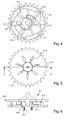
- FIGs 4 to 6 show in more detail the operation of the inertial ratchet wheel 41.
- the figure 4 is an enlargement of the figure 3 focusing on this clutch mechanism 41 that constitutes the illustrated inertial ratchet wheel.
- the hub 415 in the center the lamellae 414, the flyweights 413, which are integral with the first mobile 411, as well as the stops 416, integral with the second mobile 412, whose external toothing which meshes with the mass pinion 21 is shown.
- the stops 416 and the teeth of the second clutch mobile 412 are not located in the same plane.
- the figure 5 shows precisely this mobile 412, seen from above, and its external toothing.
- the clutch mechanism 41 thus formed is a centrifugal clutch mechanism, comprising an inertial pawl consisting of the lamellae 414 and the flyweights 413, integral. of the hub 415 of the first clutch mobile 411.
- the engagement with the stops 416, integral with the second clutch mobile 412 only take place when the lamellae 414 extend sufficiently under the effect of the radial acceleration 413, determined by the speed of rotation of the hub 415, which is also that of the first mobile 411.
- the stops 416 are arranged in the inertial ratchet wheel 41 so that the first clutch mobile 411 rotates the second clutch mobile 412 only for a given direction of rotation of the first clutch mobile 411 , which is defined by the direction of rotation of the barrel 46 during the expansion of the spring.
- the notches are indeed oriented so that the grip is optimal when the first mobile 411 rotates in the opposite direction of clockwise.
- the stops are arranged in such a way that they allow a catch and a coupling in rotation of the second mobile 412 in any direction of rotation of the first mobile 411, such that so that maximum flexibility is guaranteed for the assembly of the clutch mechanism and are adapted to all types of existing movements 1, in particular in terms of plates 6, toothing of barrels 46, and ratchet orientation 48.
- the figure 6 illustrates a sectional view along the visible plane AA on the figure 5 of the inertial ratchet wheel 41. It distinguishes the pinion 417, under the first clutch mobile 411, and the hub 415 and the flyweights 413 integral with the first mobile 411. On the top, forming a kind of cover on the first mobile 411, one can see the second mobile 412 and the stops 416 at the outer side walls of the inertial ratchet wheel 41. It is clear from this figure the relative leading-led mobiles 411 and 412 one relative to the other: the rotation of the first clutch mobile 411 causes the rotation of the second clutch mobile 412, but the rotation of the second clutch mobile never causes that of the first mobile 411. Therefore, during the movements of the oscillating mass 2 outside the triggering of the alarm mechanism, the rotation of the ground pinion 21 will only cause that of the second clutch mobile 412, without ever having any influence on the rest of the driveline 4.
- the rotation of the oscillating mass 2 in the direction S2 shown in the figures never causes the automatic winding mechanism of the movement 1 - involving the kinematic chain 3 - because of the presence of the inverting wheel 31, and this independently of the that the oscillating mass 2 is conducted, in the case of the triggering of the alarm, or leading, outside the alarm times where it can rotate freely.
- the rotation of the oscillating mass 2 has no influence on the gear of the alarm mechanism outside the second clutch mobile 412, whatever the direction of rotation, ie S1 or S2.
- a feedback of the oscillating mass 2 on the barrel 46 can be provided, as already indicated above in the description, for example to carry out an automatic winding of the alarm mechanism. However, such feedback would in principle require the addition of additional mobiles.
- the invention thus makes it possible to generate a vibration of a watch case containing the vibrating alarm mechanism according to the invention, and which uses the oscillating weight 2 of the automatic winding mechanism of the movement 1. It will also be possible to provide amplifying the vibration generated by the rotation of the oscillating mass 2 by means of an additional vibrating element.
- This additional vibrating element may for example be connected to the housing and arranged on the stroke of the oscillating mass 2 so as to be struck by the oscillating mass 2 during its driving by the second clutch mobile 412, ie when the clutch is released. alarm.
- the positioning of this additional vibrating element will however be preferably determined so that it has no interaction with the oscillating mass 2 outside the triggering of the alarm mechanism, in order to avoid disturbance of the winding of the barrel 36 by the oscillating mass 2.
- the watch comprising a vibrating alarm mechanism according to the invention may also be associated with a clock device comprising a support 7, illustrated by the figure 7 conformed to receive this watch.
- the support 7 may comprise an element generating a sound signal 8, such as for example a bell according to the variant illustrated, or a tone, configured to emit a sound when the watch is placed on the support 7 and the vibrating alarm mechanism. is triggered.
- a sound signal 8 such as for example a bell according to the variant illustrated, or a tone
- the user can choose between a silent mode when the watch is used without its support and an acoustic mode when the watch is used on its support 7, to improve comfort and functional features.
Landscapes
- Physics & Mathematics (AREA)
- General Physics & Mathematics (AREA)
- Acoustics & Sound (AREA)
- Measurement Of Unknown Time Intervals (AREA)
- Connection Of Motors, Electrical Generators, Mechanical Devices, And The Like (AREA)
- Electromechanical Clocks (AREA)
- Electric Clocks (AREA)
- Mechanical Operated Clutches (AREA)
- Braking Arrangements (AREA)
- Vibration Prevention Devices (AREA)
Abstract
Description
L'invention concerne les mouvements d'horlogerie comportant des mécanismes d'alarme ou de réveil, et en particulier de tels mouvements à remontage automatique comportant de tels mécanismes d'alarmes vibrantes, ces mouvements étant destinés à équiper des montres-bracelets, des montres de poche ou analogues.The invention relates to watch movements comprising alarm or alarm mechanisms, and in particular such self-winding movements comprising such vibrating alarm mechanisms, these movements being intended to equip wristwatches, watches and watches. pocket or the like.
Une montre bracelet commercialisée par la société Jaeger Lecoultre sous la référence « Master Grand Réveil » comprend un mécanisme de réveil permettant à une alarme de se déclencher automatiquement à un horaire prédéfini par l'utilisateur. Cette fonction réveil est assurée par un mécanisme relié au mouvement qui comprend un barillet indépendant, un système de réglage permettant de programmer l'heure de sonnerie, un système de déclenchement relié au rouage de finissage du mouvement et actionnant le réveil à l'heure prévue, et d'une sonnerie pour avertir le porteur. La sonnerie comprend d'une part un timbre sur lequel un marteau vient frapper afin de générer un signal sonore et d'autre part des moyens faisant vibrer la montre sans générer de signal sonore audible. Un commutateur permet de sélectionner soit le déclenchement d'une alarme sonore, soit d'une alarme silencieuse vibrante.A wristwatch marketed by the company Jaeger Lecoultre under the reference "Master Grand Réveil" includes an alarm mechanism allowing an alarm to be triggered automatically at a predefined time by the user. This alarm function is provided by a mechanism connected to the movement which comprises an independent cylinder, an adjustment system for programming the time of ringing, a trigger system connected to the gear train of the movement and activating the alarm at the scheduled time , and a bell to warn the wearer. The ring comprises a first stamp on which a hammer is struck to generate an audible signal and secondly means vibrating the watch without generating an audible sound signal. A switch selects either the sounding of an audible alarm or a silent vibrating alarm.
Une telle montre présente cependant des inconvénients. En effet, le mécanisme de réveil comprend des éléments spécifiques au mode de fonctionnement du mécanisme en mode d'alarme silencieuse qui augmente la complexité et l'encombrement de la structure. De plus l'amplitude de la vibration est limitée.Such a watch, however, has drawbacks. Indeed, the wakeup mechanism includes elements specific to the operating mode of the silent alarm mode mechanism that increases the complexity and bulk of the structure. In addition, the amplitude of the vibration is limited.
La présente invention a pour but principal de remédier à un ou plusieurs de ces inconvénients de l'art antérieur susmentionné en fournissant un mouvement d'horlogerie à remontage automatique comportant un mécanisme d'alarme silencieuse vibrante utilisant avantageusement des éléments du mouvement et permettant de produire une vibration de forte amplitude.The main object of the present invention is to remedy one or more of these disadvantages of the above-mentioned prior art in providing a self-winding clockwork movement comprising a vibrating silent alarm mechanism advantageously using elements of the movement and making it possible to produce a vibration of high amplitude.
L'invention a également pour but de fournir un mouvement d'horlogerie comprenant un tel dispositif d'alarme présentant une conception particulièrement simple et peu coûteuse à mettre en oeuvre dans le mouvement.The invention also aims to provide a watch movement comprising such an alarm device having a particularly simple and inexpensive design to implement in the movement.
A cet effet l'invention concerne un mouvement d'horlogerie comprenant une première et une deuxième source d'énergie, la première source d'énergie étant couplée à une masse oscillante par une première chaîne cinématique pour le remontage automatique dudit mouvement, et la deuxième source d'énergie étant couplée d'une part à un dispositif d'actionnement, et d'autre part à un élément vibrant par une deuxième chaîne cinématique pour former un mécanisme d'alarme vibrante pouvant être déclenché à un horaire prédéterminé. Le mouvement d'horlogerie est caractérisé en ce que l'élément vibrant du mécanisme d'alarme vibrante est la masse oscillante.For this purpose the invention relates to a clockwork movement comprising a first and a second energy source, the first energy source being coupled to an oscillating mass by a first kinematic chain for the automatic winding of said movement, and the second energy source being coupled on the one hand to an actuating device, and on the other hand to a vibrating element by a second kinematic chain to form a vibrating alarm mechanism that can be triggered at a predetermined time. The watch movement is characterized in that the vibrating element of the vibrating alarm mechanism is the oscillating mass.
Le mécanisme d'alarme vibrante obtenu présente l'avantage d'être simplifié, puisque le balourd naturel de la masse oscillante du mécanisme de remontage automatique est également utilisé pour générer la vibration de l'alarme. Il en résulte un gain de place pour loger d'autres modules dans le boitier de la montre, comme par exemple un module chronographe, sans nécessiter d'augmentation du calibre de la montre. Par ailleurs, l'utilisation de la masse oscillante comme élément vibrant procure des vibrations d'une plus grande amplitude qu'avec un élément vibrant traditionnel, d'une part, et diminue d'autre part parallèlement le nombre de pièces à monter. Il en résulte un assemblage plus facile et une diminution des coûts de fabrication pour une montre comportant un tel mouvement.The vibrating alarm mechanism obtained has the advantage of being simplified, since the natural unbalance of the oscillating weight of the automatic winding mechanism is also used to generate the vibration of the alarm. This results in a saving of space to accommodate other modules in the case of the watch, such as a chronograph module, without requiring an increase in the caliber of the watch. Furthermore, the use of the oscillating mass as a vibrating element provides vibrations of greater amplitude than with a traditional vibrating element, on the one hand, and on the other hand decreases parallel the number of parts to be mounted. This results in easier assembly and lower manufacturing costs for a watch with such a movement.
D'autres caractéristiques et avantages de l'invention ressortiront clairement de la description ci-après, en référence aux dessins annexés, dans lesquels :
- la
figure 1 est une vue en perspective éclatée d'une partie du mouvement formant une alarme vibrante selon un mode de réalisation préférentiel de l'invention; - la
figure 2 est une vue en perspective du mouvement de lafigure 1 assemblé; - la
figure 3 est une vue de dessus du mouvement de lafigure 1 en coupe au niveau du support de la masse oscillante; - la
figure 4 est agrandissement de la vue en coupe du dispositif d'embrayage vu sur lafigure 3 ; - la
figure 5 est une vue de dessus du dispositif d'embrayage de lafigure 4 . - la
figure 6 est une vue en coupe sagittale du dispositif d'embrayage desfigures 4 et 5 . - la
figure 7 est une vue d'un support pourvu d'un élément générant un signal sonore, destiné à recevoir une montre pourvue du mécanisme d'alarme de l'invention.
- the
figure 1 is an exploded perspective view of part of the motion forming a vibrating alarm according to a preferred embodiment of the invention; - the
figure 2 is a perspective view of the movement of thefigure 1 assembled; - the
figure 3 is a top view of the movement of thefigure 1 in section at the support of the oscillating mass; - the
figure 4 is enlargement of the sectional view of the clutch device seen on thefigure 3 ; - the
figure 5 is a top view of the clutch device of thefigure 4 . - the
figure 6 is a sagittal sectional view of the clutch device of theFigures 4 and 5 . - the
figure 7 is a view of a support provided with an element generating a sound signal, for receiving a watch provided with the alarm mechanism of the invention.
La
Comme représenté sur la
Comme illustré sur la
Le mouvement 1 comprend également un mécanisme d'alarme vibrante 4, qui comprend une source d'énergie 46, un dispositif d'actionnement 48, une chaîne cinématique 4 et un élément vibrant 2. Selon le mode de réalisation illustré par la
L'élément vibrant du mécanise d'alarme vibrante est la masse oscillante 2, qui est entraînée en rotation en sortie d'une chaîne cinématique 4 entraînée par la rotation du barillet 46, et qui comprend de préférence un mécanisme d'embrayage 41, décrit plus loin en référence aux
Selon une variante préférentielle de l'invention, le mécanisme d'alarme vibrante comprend un premier mobile de réduction 44, formé d'un pignon et d'une roue solidaires en rotation, similairement aux mobiles de réduction 32,34 de la chaîne cinématique 3 associée au remontage automatique du mouvement. Toutefois, contrairement au mobile 34 illustré sur la
Selon le mode de réalisation préférentiel de l'invention, l'énergie stockée dans le barillet 46 et libérée lors du déclenchement du mécanisme d'alarme est obtenue par l'intermédiaire d'un mécanisme de remontage manuel. On peut distinguer en effet une roue de remontage 47, située côte à côte par rapport à la roue de remontage 37 du barillet 36. Cette roue de remontage 47 engrène avec la roue de rochet 43 du barillet 46, et permet donc de remonter le ressort à l'intérieur du barillet. Les roues à rochet 43 et la roue de remontage 47 sont montées à rotation par rapport au pont 45. La roue de remontage 47 peut être mise en rotation par l'utilisateur qui veut effectuer un remontage manuel de la montre par actionnement d'une tige ou d'une couronne munie d'une molette de préhension extérieure (non illustrée, similairement au mécanisme de remontage manuel associé à la roue 37).According to the preferred embodiment of the invention, the energy stored in the
Lors du déclenchement de l'alarme, le cliquet 48 libère l'énergie stockée dans le ressort du barillet 46 et met en rotation de la denture périphérique du barillet 46. Selon un mode de réalisation préférentiel, l'énergie maximale emmagasinée dans le barillet 46 et les rapports d'engrenage du rouage pour de la chaîne cinématique 4 qui entraîne le premier mobile d'embrayage 411 sont déterminés de telle sorte que la masse oscillante 2, faisant office d'élément vibrant, tourne durant environ 15 secondes après le déclenchement de l'alarme. D'autre part, les rapports d'engrenage des mobiles de réduction 42,44 pour déterminer le rapport des vitesses entre la rotation du barillet 46 et celle de la masse oscillante sont calculés pour être environ cinq fois plus petits que ceux utilisés dans la première chaîne cinématique 3 de remontage automatique du mouvement 1, où il s'agit de déterminer le rapport des vitesses entre le barillet fournissant la réserve de marche 36 et la masse oscillante. Ces rapports ainsi que l'énergie qui peut être emmagasinée dépendra notamment du temps de vibration désiré pour l'alarme, qui pourra de préférence être déterminé entre 10 et 20 secondes. Selon un mode de réalisation préférentiel, le temps de vibration pourra être ajusté par l'utilisateur, agissant sur la roue de remontage 47, grâce à la consultation d'une jauge visuelle couplée au barillet 46, et qui détermine le niveau d'énergie stockée dans ce barillet.When triggering the alarm, the
La
Sur la
Contrairement au mécanisme de remontage automatique du mouvement 1 utilisant la chaîne cinématique 3, la chaîne cinématique 4 permet donc de libérer l'énergie du barillet 46 et non pas d'en stocker dedans. Le rouage du mécanisme d'alarme ne possède donc pas, comme celui associé au barillet 36, de mécanisme de remontage automatique, mais seulement un mécanisme de remontage manuel. Pour ce faire, on utilise la roue de remontage 47, qui engrène sur la roue à rochet 43 du barillet 46, en actionnant par exemple une molette externe, comme expliqué précédemment dans la description. Bien qu'aucun mécanisme de remontage automatique ne soit prévu selon le mode de réalisation préférentiel illustré, il sera toutefois possible d'en ajouter un, par exemple par l'intermédiaire d'un rouage additionnel; ceci présentera toutefois l'inconvénient de nécessiter plus de place dans le boîtier.Unlike the automatic winding mechanism of the
La
Le mécanisme d'embrayage 41 utilisé selon le mode de réalisation préférentiel illustré sur cette figure consiste en une roue à cliquet inertiel, dont on voit les éléments suivant en coupe (NB : les références ci-après sont données en référence à la
Bien que selon le mode de réalisation préférentiel illustré, les deux éléments 31 et 41 engrènent directement avec le pignon de masse et aient ainsi le même sens de rotation, on pourra aussi placer un rouage intermédiaire entre l'un d'eux et le pignon de masse 21 pour inverser le sens de rotation de ces éléments l'un par rapport à l'autre si nécessaire. Il est aussi possible d'envisager un rouage permettant d'effectuer le remontage automatique du mouvement 1 pour les deux sens de rotation de la masse oscillante, par exemple en engrenant une roue additionnelle sur le pignon de masse 21 d'une part, et sur une autre roue inverseuse 31' (non représentée) d'autre part, similaire à la roue inverseuse 31, de telle sorte que quel que soit le sens de rotation S1 ou S2 du pignon de masse, l'une des deux roues inverseuses 31 ou 31' procède toujours au remontage automatique du mouvement : si la roue 31 est entraînante, le sens de la roue inverseuse 31' engendrera un décliquetage du mobile entraîné, et réciproquement, puisque les roues inverseuses 31 et 31' seraient alors toujours entraînées dans un sens opposé. Ce mode de réalisation présente toutefois les mêmes inconvénients que celui selon lequel le sens d'entraînement de la masse oscillante 2 par le mécanisme d'alarme correspond à celui du remontage automatique du barillet 36 du mouvement, à savoir que des pertes d'énergie sont à envisager pour entraîner le vibreur, d'une part, et d'autre part que le couple à libérer par le barillet 46 doit être très grand pour assurer le fonctionnement du déclenchement de l'alarme quel que soit l'état de tension du ressort à l'intérieur du barillet 36.Although according to the preferred embodiment illustrated, the two
La suite de la description traite des
Comme on peut le constater sur la
La
On pourra noter que selon le mode de réalisation préférentiel de l'invention illustré par les
L'invention permet ainsi de générer une vibration d'un boîtier de montre contenant le mécanisme d'alarme vibrante selon l'invention, et qui utilise la masse oscillante 2 du mécanisme de remontage automatique du mouvement 1. On pourra par ailleurs prévoir d'amplifier la vibration générée par la rotation de la masse oscillante 2 par l'intermédiaire d'un élément vibrant additionnel. Cet élément vibrant additionnel pourra par exemple être relié au boîtier et disposé sur la course de la masse oscillante 2 de façon à être heurté par la masse oscillante 2 durant son entraînement par le deuxième mobile d'embrayage 412, i.e. lors du déclenchement de l'alarme. Le positionnement de cet élément vibrant additionnel sera toutefois de préférence déterminé de telle sorte qu'il n'ait aucune interaction avec la masse oscillante 2 en dehors du déclenchement du mécanisme d'alarme, afin d'éviter le dérangement du remontage du barillet 36 par la masse oscillante 2.The invention thus makes it possible to generate a vibration of a watch case containing the vibrating alarm mechanism according to the invention, and which uses the
La montre comportant un mécanisme d'alarme vibrante selon l'invention pourra également être associée à un dispositif d'horlogerie comprenant un support 7, illustré par la
Claims (6)
Priority Applications (1)
| Application Number | Priority Date | Filing Date | Title |
|---|---|---|---|
| EP09167567.8A EP2214065B1 (en) | 2008-12-01 | 2008-12-01 | Timepiece movement equipped with a vibrating alarm |
Applications Claiming Priority (2)
| Application Number | Priority Date | Filing Date | Title |
|---|---|---|---|
| EP09167567.8A EP2214065B1 (en) | 2008-12-01 | 2008-12-01 | Timepiece movement equipped with a vibrating alarm |
| EP08020803A EP2175329B1 (en) | 2008-12-01 | 2008-12-01 | Timepiece movement equipped with a vibrating alarm |
Related Parent Applications (2)
| Application Number | Title | Priority Date | Filing Date |
|---|---|---|---|
| EP08020803.6 Division | 2008-12-01 | ||
| EP08020803A Division EP2175329B1 (en) | 2008-12-01 | 2008-12-01 | Timepiece movement equipped with a vibrating alarm |
Publications (2)
| Publication Number | Publication Date |
|---|---|
| EP2214065A1 true EP2214065A1 (en) | 2010-08-04 |
| EP2214065B1 EP2214065B1 (en) | 2017-02-08 |
Family
ID=40638152
Family Applications (3)
| Application Number | Title | Priority Date | Filing Date |
|---|---|---|---|
| EP09167567.8A Active EP2214065B1 (en) | 2008-12-01 | 2008-12-01 | Timepiece movement equipped with a vibrating alarm |
| EP08020803A Active EP2175329B1 (en) | 2008-12-01 | 2008-12-01 | Timepiece movement equipped with a vibrating alarm |
| EP09177515A Withdrawn EP2192455A1 (en) | 2008-12-01 | 2009-11-30 | Timepiece movement equipped with an inertia clutch |
Family Applications After (2)
| Application Number | Title | Priority Date | Filing Date |
|---|---|---|---|
| EP08020803A Active EP2175329B1 (en) | 2008-12-01 | 2008-12-01 | Timepiece movement equipped with a vibrating alarm |
| EP09177515A Withdrawn EP2192455A1 (en) | 2008-12-01 | 2009-11-30 | Timepiece movement equipped with an inertia clutch |
Country Status (8)
| Country | Link |
|---|---|
| US (2) | US8305848B2 (en) |
| EP (3) | EP2214065B1 (en) |
| JP (2) | JP5543182B2 (en) |
| KR (2) | KR101586091B1 (en) |
| CN (2) | CN101750957B (en) |
| AT (1) | ATE498860T1 (en) |
| DE (1) | DE602008005027D1 (en) |
| HK (2) | HK1145548A1 (en) |
Cited By (1)
| Publication number | Priority date | Publication date | Assignee | Title |
|---|---|---|---|---|
| CN107203121A (en) * | 2016-03-16 | 2017-09-26 | 劳力士有限公司 | table transmission device |
Families Citing this family (23)
| Publication number | Priority date | Publication date | Assignee | Title |
|---|---|---|---|---|
| EP2214065B1 (en) * | 2008-12-01 | 2017-02-08 | The Swatch Group Research and Development Ltd. | Timepiece movement equipped with a vibrating alarm |
| EP2339413B1 (en) * | 2009-12-22 | 2012-09-12 | The Swatch Group Research and Development Ltd. | Timepiece movement equipped with a vibrating alarm |
| EP2787399B1 (en) * | 2011-12-13 | 2015-07-29 | ETA SA Manufacture Horlogère Suisse | Modular clock movement with functional modules |
| AU351858S (en) * | 2013-04-16 | 2013-11-04 | Swatch Ag Swatch Sa Swatch Ltd | Watch movement |
| USD739286S1 (en) * | 2013-04-16 | 2015-09-22 | Swatch Ltd | Watch movement |
| USD759527S1 (en) * | 2013-10-16 | 2016-06-21 | Swatch Ltd | Oscillating weight |
| CN104678749A (en) * | 2013-11-30 | 2015-06-03 | 武汉蜀泰科技有限公司 | Vibration time telling quartz device |
| ES2623896T3 (en) * | 2014-01-15 | 2017-07-12 | Audemars Piguet (Renaud Et Papi) Sa | Inverter for watchmaking |
| EP3198344B1 (en) * | 2014-09-25 | 2019-04-24 | The Swatch Group Research and Development Ltd | Interaction between two timepiece components |
| JP6588700B2 (en) * | 2014-12-09 | 2019-10-09 | 株式会社メガチップス | Correction data generation method, image correction apparatus, image correction method, and image correction system |
| EP3070540B1 (en) * | 2015-03-18 | 2017-11-15 | Glashütter Uhrenbetrieb GmbH | Striking mechanism for a clock with hammer with resilient adjustable stop |
| ES2657167T3 (en) * | 2015-06-11 | 2018-03-01 | Société Anonyme de la Manufacture d'Horlogerie Audemars Piguet & Cie | Clock and watch inverter with automatic reassembly that includes your application |
| CN105232252A (en) * | 2015-09-21 | 2016-01-13 | 沈阳化工大学 | Safe movement sickbed |
| CH712031A1 (en) * | 2016-01-13 | 2017-07-14 | Richemont Int Sa | Watchmaking mechanism with tourbillon. |
| EP3376308B1 (en) * | 2017-03-17 | 2019-11-13 | Montres Jaquet Droz SA | Winding mechanism of a timepiece |
| EP3435174B1 (en) * | 2017-07-25 | 2021-06-16 | Blancpain SA | Chime mode selector for watch or timepiece |
| USD891284S1 (en) * | 2018-03-02 | 2020-07-28 | Tudor Watch U.S.A., Llc | Watch movement |
| USD894778S1 (en) * | 2018-03-02 | 2020-09-01 | Tudor Watch U.S.A., Llc | Watch movement |
| USD894777S1 (en) * | 2018-03-02 | 2020-09-01 | Tudor Watch U.S.A., Llc | Watch movement |
| USD894779S1 (en) * | 2018-03-06 | 2020-09-01 | Rolex Watch U.S.A., Inc. | Watch movement |
| DE102019130516B3 (en) * | 2019-11-12 | 2021-04-29 | Lange Uhren Gmbh | Alarm trigger device |
| EP3865953A1 (en) * | 2020-02-17 | 2021-08-18 | The Swatch Group Research and Development Ltd | Oscillating winding mass provided with a rotary decorative element for automatic movement of a timepiece |
| EP3982209B1 (en) * | 2020-10-06 | 2023-06-07 | The Swatch Group Research and Development Ltd | Device for limiting the winding of a timepiece barrel |
Citations (2)
| Publication number | Priority date | Publication date | Assignee | Title |
|---|---|---|---|---|
| CH161131A (en) | 1932-04-15 | 1933-04-15 | Balland & Co | Snap-in device. |
| FR2234591A1 (en) * | 1973-06-25 | 1975-01-17 | Citizen Watch Co Ltd |
Family Cites Families (26)
| Publication number | Priority date | Publication date | Assignee | Title |
|---|---|---|---|---|
| US1994581A (en) * | 1934-09-05 | 1935-03-19 | Lazzarini Aldo | Automatic change-gear transmission mechanism for automobiles |
| US2135917A (en) * | 1936-11-02 | 1938-11-08 | Frederick W Seybold | Automatic transmission |
| US2305666A (en) * | 1941-06-27 | 1942-12-22 | Bolsey Jacques | Winding mechanism |
| US2739682A (en) * | 1951-06-11 | 1956-03-27 | Hamilton Watch Co | Overrunning clutch |
| US2667737A (en) * | 1952-02-28 | 1954-02-02 | Gazda Antoine | Self-winding timepiece |
| US2756559A (en) * | 1952-04-03 | 1956-07-31 | Hamilton Watch Co | Automatic watch mainspring winding mechanism |
| US2874532A (en) * | 1954-01-08 | 1959-02-24 | Baier Paul | Self-winding watch |
| CH330203A (en) * | 1956-03-05 | 1958-05-31 | Omega Brandt & Freres Sa Louis | Wristwatch-alarm clock with automatic winding device by moving mass |
| US3019595A (en) * | 1957-08-20 | 1962-02-06 | Murrle Kurt | Inertia wound watch with overwind preventer |
| CH343928A (en) * | 1957-12-20 | 1959-12-31 | Schild Sa A | Wristwatch alarm clock |
| US3315460A (en) * | 1965-09-20 | 1967-04-25 | Kienzle Uhrenfabriken Gmbh | Alarm clock clapper retarder |
| FR2196490B1 (en) * | 1972-08-18 | 1976-08-13 | Schild Sa A | |
| US5023853A (en) * | 1988-06-27 | 1991-06-11 | Masayuki Kawata | Electric apparatus with silent alarm |
| JP3224229B2 (en) * | 1991-07-05 | 2001-10-29 | シチズン時計株式会社 | Clock with silence alarm |
| EP0585470B1 (en) * | 1992-03-18 | 1997-09-10 | Citizen Watch Co. Ltd. | Electronic machine with vibration alarm |
| JPH10253776A (en) * | 1997-03-10 | 1998-09-25 | Casio Comput Co Ltd | Electronic apparatus |
| CN2389381Y (en) * | 1999-09-14 | 2000-07-26 | 应东义 | Beater for time-piece |
| EP1708051A1 (en) | 2005-03-31 | 2006-10-04 | Zenith International SA | Timepiece comprising an alarm |
| EP1843225B1 (en) * | 2006-04-07 | 2009-07-15 | ETA SA Manufacture Horlogère Suisse | Mechanical reverser for rotational and unidirectional driving of a wheel |
| ATE516523T1 (en) * | 2006-04-12 | 2011-07-15 | Montres Breguet Sa | CLOCK WITH A STRIKE COMPRISING A SINGLE BARREL |
| JP2008111802A (en) * | 2006-10-31 | 2008-05-15 | Seiko Instruments Inc | One-way rotating clutch wheel, self-winding mechanism equipped therewith, and self-winding watch |
| DE602006004465D1 (en) * | 2006-10-31 | 2009-02-05 | Swatch Group Man Serv Ag | Oscillating mass for recharging the power source of a portable instrument |
| EP1944662A1 (en) * | 2007-01-15 | 2008-07-16 | Vaucher Manufacture Fleurier SA | Hour chiming mechanism |
| EP1980922B1 (en) * | 2007-04-12 | 2013-03-06 | LVMH Swiss Manufactures SA | Clock piece including a discrete striking mechanism |
| JP3142661U (en) * | 2008-04-10 | 2008-06-19 | パートナー産業株式会社 | Centrifugal clutch device |
| EP2214065B1 (en) * | 2008-12-01 | 2017-02-08 | The Swatch Group Research and Development Ltd. | Timepiece movement equipped with a vibrating alarm |
-
2008
- 2008-12-01 EP EP09167567.8A patent/EP2214065B1/en active Active
- 2008-12-01 AT AT08020803T patent/ATE498860T1/en not_active IP Right Cessation
- 2008-12-01 EP EP08020803A patent/EP2175329B1/en active Active
- 2008-12-01 DE DE602008005027T patent/DE602008005027D1/en active Active
-
2009
- 2009-11-17 KR KR1020090110589A patent/KR101586091B1/en not_active IP Right Cessation
- 2009-11-30 EP EP09177515A patent/EP2192455A1/en not_active Withdrawn
- 2009-12-01 CN CN2009102466791A patent/CN101750957B/en active Active
- 2009-12-01 KR KR1020090117475A patent/KR20100062939A/en not_active Application Discontinuation
- 2009-12-01 JP JP2009273486A patent/JP5543182B2/en active Active
- 2009-12-01 CN CN2009102466823A patent/CN101750952B/en active Active
- 2009-12-01 US US12/628,366 patent/US8305848B2/en active Active
- 2009-12-01 US US12/628,529 patent/US7896542B2/en active Active
- 2009-12-01 JP JP2009273494A patent/JP5543183B2/en active Active
-
2010
- 2010-12-21 HK HK10111913.9A patent/HK1145548A1/en unknown
- 2010-12-21 HK HK10111915.7A patent/HK1145549A1/en unknown
Patent Citations (2)
| Publication number | Priority date | Publication date | Assignee | Title |
|---|---|---|---|---|
| CH161131A (en) | 1932-04-15 | 1933-04-15 | Balland & Co | Snap-in device. |
| FR2234591A1 (en) * | 1973-06-25 | 1975-01-17 | Citizen Watch Co Ltd |
Cited By (2)
| Publication number | Priority date | Publication date | Assignee | Title |
|---|---|---|---|---|
| CN107203121A (en) * | 2016-03-16 | 2017-09-26 | 劳力士有限公司 | table transmission device |
| CN107203121B (en) * | 2016-03-16 | 2022-01-28 | 劳力士有限公司 | Watch driving device |
Also Published As
| Publication number | Publication date |
|---|---|
| CN101750957A (en) | 2010-06-23 |
| CN101750952A (en) | 2010-06-23 |
| JP2010127944A (en) | 2010-06-10 |
| US8305848B2 (en) | 2012-11-06 |
| KR20100062913A (en) | 2010-06-10 |
| EP2214065B1 (en) | 2017-02-08 |
| KR20100062939A (en) | 2010-06-10 |
| US20100135126A1 (en) | 2010-06-03 |
| HK1145549A1 (en) | 2011-04-21 |
| HK1145548A1 (en) | 2011-04-21 |
| CN101750957B (en) | 2013-01-16 |
| JP5543182B2 (en) | 2014-07-09 |
| KR101586091B1 (en) | 2016-01-15 |
| DE602008005027D1 (en) | 2011-03-31 |
| JP5543183B2 (en) | 2014-07-09 |
| EP2175329A1 (en) | 2010-04-14 |
| EP2175329B1 (en) | 2011-02-16 |
| US7896542B2 (en) | 2011-03-01 |
| US20100135127A1 (en) | 2010-06-03 |
| EP2192455A1 (en) | 2010-06-02 |
| ATE498860T1 (en) | 2011-03-15 |
| CN101750952B (en) | 2013-01-16 |
| JP2010127945A (en) | 2010-06-10 |
Similar Documents
| Publication | Publication Date | Title |
|---|---|---|
| EP2175329B1 (en) | Timepiece movement equipped with a vibrating alarm | |
| EP2339413B1 (en) | Timepiece movement equipped with a vibrating alarm | |
| EP1845425B1 (en) | Chiming timepiece with a single barrel | |
| EP2498145B1 (en) | Ringing mechanism with differentiated alarms | |
| WO2005096104A1 (en) | Watch movement comprising several barrels | |
| EP3198343B1 (en) | Striking mechanism | |
| EP1664941B8 (en) | Watch movement with an animation | |
| EP2376986B1 (en) | Horological movement with automatic winding and moving escapement | |
| EP2515186A1 (en) | Gear-train for timepiece | |
| EP3435176B1 (en) | Torque smoothing for timepiece with chiming mechanism, in particular with chiming mechanism | |
| CH700044A2 (en) | watch movement equipped with a vibrating alarm. | |
| CH716841B1 (en) | Chronograph watch movement. | |
| EP2488921B1 (en) | Energy source for a striking mechanism, and timepiece provided with such an energy source | |
| CH710521B1 (en) | Device for generating electricity on demand for timepieces. | |
| CH702421A2 (en) | Timepiece movement for use in case of watch e.g. wrist watch, has energy source coupled to activating device and vibrating element by another kinematic chain for forming vibrating alarm mechanism that is triggered at predetermined time | |
| CH714617A2 (en) | Movement and timepiece. | |
| EP2735923A1 (en) | Drive mechanism for the hands of an electro-mechanical watch, provided with a locking device | |
| WO2000062129A1 (en) | Motor for clock watch movement | |
| CH717672B1 (en) | Mechanism for triggering an animation for a timepiece or jewelry piece. | |
| EP3944027A1 (en) | Portable object, in particular a wristwatch, comprising a power supply device provided with an electromechanical converter | |
| CH715502B1 (en) | Mechanical clock module for counting and displaying a user's physical activity. | |
| WO2020100004A1 (en) | Timepiece comprising two power sources | |
| CH698435B1 (en) | Timepiece movement for use in watchmaking piece, has regulating device provided with balance spring, hairspring and constant force device, where constant force device is formed of spatial unit separated from regulating device | |
| EP1925994A1 (en) | Chiming mechanism | |
| CH713779A2 (en) | Movement and timepiece with two balance springs. |
Legal Events
| Date | Code | Title | Description |
|---|---|---|---|
| PUAI | Public reference made under article 153(3) epc to a published international application that has entered the european phase |
Free format text: ORIGINAL CODE: 0009012 |
|
| AC | Divisional application: reference to earlier application |
Ref document number: 2175329 Country of ref document: EP Kind code of ref document: P |
|
| AK | Designated contracting states |
Kind code of ref document: A1 Designated state(s): AT BE BG CH CY CZ DE DK EE ES FI FR GB GR HR HU IE IS IT LI LT LU LV MC MT NL NO PL PT RO SE SI SK TR |
|
| 17P | Request for examination filed |
Effective date: 20110204 |
|
| 17Q | First examination report despatched |
Effective date: 20110223 |
|
| RIC1 | Information provided on ipc code assigned before grant |
Ipc: G04B 1/12 20060101ALI20160811BHEP Ipc: G04B 5/12 20060101ALI20160811BHEP Ipc: G04B 25/04 20060101ALI20160811BHEP Ipc: G04B 23/12 20060101AFI20160811BHEP Ipc: G04B 11/00 20060101ALI20160811BHEP |
|
| GRAP | Despatch of communication of intention to grant a patent |
Free format text: ORIGINAL CODE: EPIDOSNIGR1 |
|
| INTG | Intention to grant announced |
Effective date: 20160920 |
|
| RIN1 | Information on inventor provided before grant (corrected) |
Inventor name: BORN, JEAN-JACQUES Inventor name: NICOLAS, CEDRIC |
|
| GRAS | Grant fee paid |
Free format text: ORIGINAL CODE: EPIDOSNIGR3 |
|
| GRAA | (expected) grant |
Free format text: ORIGINAL CODE: 0009210 |
|
| AC | Divisional application: reference to earlier application |
Ref document number: 2175329 Country of ref document: EP Kind code of ref document: P |
|
| AK | Designated contracting states |
Kind code of ref document: B1 Designated state(s): AT BE BG CH CY CZ DE DK EE ES FI FR GB GR HR HU IE IS IT LI LT LU LV MC MT NL NO PL PT RO SE SI SK TR |
|
| REG | Reference to a national code |
Ref country code: GB Ref legal event code: FG4D Free format text: NOT ENGLISH |
|
| REG | Reference to a national code |
Ref country code: CH Ref legal event code: EP Ref country code: CH Ref legal event code: NV Representative=s name: ICB INGENIEURS CONSEILS EN BREVETS SA, CH Ref country code: AT Ref legal event code: REF Ref document number: 867136 Country of ref document: AT Kind code of ref document: T Effective date: 20170215 |
|
| REG | Reference to a national code |
Ref country code: IE Ref legal event code: FG4D Free format text: LANGUAGE OF EP DOCUMENT: FRENCH |
|
| REG | Reference to a national code |
Ref country code: DE Ref legal event code: R096 Ref document number: 602008048729 Country of ref document: DE |
|
| REG | Reference to a national code |
Ref country code: LT Ref legal event code: MG4D |
|
| REG | Reference to a national code |
Ref country code: NL Ref legal event code: MP Effective date: 20170208 |
|
| REG | Reference to a national code |
Ref country code: AT Ref legal event code: MK05 Ref document number: 867136 Country of ref document: AT Kind code of ref document: T Effective date: 20170208 |
|
| PG25 | Lapsed in a contracting state [announced via postgrant information from national office to epo] |
Ref country code: NO Free format text: LAPSE BECAUSE OF FAILURE TO SUBMIT A TRANSLATION OF THE DESCRIPTION OR TO PAY THE FEE WITHIN THE PRESCRIBED TIME-LIMIT Effective date: 20170508 Ref country code: FI Free format text: LAPSE BECAUSE OF FAILURE TO SUBMIT A TRANSLATION OF THE DESCRIPTION OR TO PAY THE FEE WITHIN THE PRESCRIBED TIME-LIMIT Effective date: 20170208 Ref country code: HR Free format text: LAPSE BECAUSE OF FAILURE TO SUBMIT A TRANSLATION OF THE DESCRIPTION OR TO PAY THE FEE WITHIN THE PRESCRIBED TIME-LIMIT Effective date: 20170208 Ref country code: LT Free format text: LAPSE BECAUSE OF FAILURE TO SUBMIT A TRANSLATION OF THE DESCRIPTION OR TO PAY THE FEE WITHIN THE PRESCRIBED TIME-LIMIT Effective date: 20170208 Ref country code: GR Free format text: LAPSE BECAUSE OF FAILURE TO SUBMIT A TRANSLATION OF THE DESCRIPTION OR TO PAY THE FEE WITHIN THE PRESCRIBED TIME-LIMIT Effective date: 20170509 |
|
| PG25 | Lapsed in a contracting state [announced via postgrant information from national office to epo] |
Ref country code: AT Free format text: LAPSE BECAUSE OF FAILURE TO SUBMIT A TRANSLATION OF THE DESCRIPTION OR TO PAY THE FEE WITHIN THE PRESCRIBED TIME-LIMIT Effective date: 20170208 Ref country code: SE Free format text: LAPSE BECAUSE OF FAILURE TO SUBMIT A TRANSLATION OF THE DESCRIPTION OR TO PAY THE FEE WITHIN THE PRESCRIBED TIME-LIMIT Effective date: 20170208 Ref country code: PT Free format text: LAPSE BECAUSE OF FAILURE TO SUBMIT A TRANSLATION OF THE DESCRIPTION OR TO PAY THE FEE WITHIN THE PRESCRIBED TIME-LIMIT Effective date: 20170608 Ref country code: BG Free format text: LAPSE BECAUSE OF FAILURE TO SUBMIT A TRANSLATION OF THE DESCRIPTION OR TO PAY THE FEE WITHIN THE PRESCRIBED TIME-LIMIT Effective date: 20170508 Ref country code: NL Free format text: LAPSE BECAUSE OF FAILURE TO SUBMIT A TRANSLATION OF THE DESCRIPTION OR TO PAY THE FEE WITHIN THE PRESCRIBED TIME-LIMIT Effective date: 20170208 Ref country code: ES Free format text: LAPSE BECAUSE OF FAILURE TO SUBMIT A TRANSLATION OF THE DESCRIPTION OR TO PAY THE FEE WITHIN THE PRESCRIBED TIME-LIMIT Effective date: 20170208 Ref country code: LV Free format text: LAPSE BECAUSE OF FAILURE TO SUBMIT A TRANSLATION OF THE DESCRIPTION OR TO PAY THE FEE WITHIN THE PRESCRIBED TIME-LIMIT Effective date: 20170208 |
|
| PG25 | Lapsed in a contracting state [announced via postgrant information from national office to epo] |
Ref country code: CZ Free format text: LAPSE BECAUSE OF FAILURE TO SUBMIT A TRANSLATION OF THE DESCRIPTION OR TO PAY THE FEE WITHIN THE PRESCRIBED TIME-LIMIT Effective date: 20170208 Ref country code: RO Free format text: LAPSE BECAUSE OF FAILURE TO SUBMIT A TRANSLATION OF THE DESCRIPTION OR TO PAY THE FEE WITHIN THE PRESCRIBED TIME-LIMIT Effective date: 20170208 Ref country code: SK Free format text: LAPSE BECAUSE OF FAILURE TO SUBMIT A TRANSLATION OF THE DESCRIPTION OR TO PAY THE FEE WITHIN THE PRESCRIBED TIME-LIMIT Effective date: 20170208 Ref country code: IT Free format text: LAPSE BECAUSE OF FAILURE TO SUBMIT A TRANSLATION OF THE DESCRIPTION OR TO PAY THE FEE WITHIN THE PRESCRIBED TIME-LIMIT Effective date: 20170208 Ref country code: EE Free format text: LAPSE BECAUSE OF FAILURE TO SUBMIT A TRANSLATION OF THE DESCRIPTION OR TO PAY THE FEE WITHIN THE PRESCRIBED TIME-LIMIT Effective date: 20170208 |
|
| REG | Reference to a national code |
Ref country code: DE Ref legal event code: R097 Ref document number: 602008048729 Country of ref document: DE |
|
| REG | Reference to a national code |
Ref country code: FR Ref legal event code: PLFP Year of fee payment: 10 |
|
| PG25 | Lapsed in a contracting state [announced via postgrant information from national office to epo] |
Ref country code: DK Free format text: LAPSE BECAUSE OF FAILURE TO SUBMIT A TRANSLATION OF THE DESCRIPTION OR TO PAY THE FEE WITHIN THE PRESCRIBED TIME-LIMIT Effective date: 20170208 Ref country code: PL Free format text: LAPSE BECAUSE OF FAILURE TO SUBMIT A TRANSLATION OF THE DESCRIPTION OR TO PAY THE FEE WITHIN THE PRESCRIBED TIME-LIMIT Effective date: 20170208 |
|
| PLBE | No opposition filed within time limit |
Free format text: ORIGINAL CODE: 0009261 |
|
| STAA | Information on the status of an ep patent application or granted ep patent |
Free format text: STATUS: NO OPPOSITION FILED WITHIN TIME LIMIT |
|
| 26N | No opposition filed |
Effective date: 20171109 |
|
| PG25 | Lapsed in a contracting state [announced via postgrant information from national office to epo] |
Ref country code: SI Free format text: LAPSE BECAUSE OF FAILURE TO SUBMIT A TRANSLATION OF THE DESCRIPTION OR TO PAY THE FEE WITHIN THE PRESCRIBED TIME-LIMIT Effective date: 20170208 |
|
| REG | Reference to a national code |
Ref country code: IE Ref legal event code: MM4A |
|
| PG25 | Lapsed in a contracting state [announced via postgrant information from national office to epo] |
Ref country code: LU Free format text: LAPSE BECAUSE OF NON-PAYMENT OF DUE FEES Effective date: 20171201 Ref country code: MT Free format text: LAPSE BECAUSE OF FAILURE TO SUBMIT A TRANSLATION OF THE DESCRIPTION OR TO PAY THE FEE WITHIN THE PRESCRIBED TIME-LIMIT Effective date: 20170208 |
|
| REG | Reference to a national code |
Ref country code: BE Ref legal event code: MM Effective date: 20171231 |
|
| PG25 | Lapsed in a contracting state [announced via postgrant information from national office to epo] |
Ref country code: IE Free format text: LAPSE BECAUSE OF NON-PAYMENT OF DUE FEES Effective date: 20171201 |
|
| PG25 | Lapsed in a contracting state [announced via postgrant information from national office to epo] |
Ref country code: BE Free format text: LAPSE BECAUSE OF NON-PAYMENT OF DUE FEES Effective date: 20171231 |
|
| PGFP | Annual fee paid to national office [announced via postgrant information from national office to epo] |
Ref country code: TR Payment date: 20181017 Year of fee payment: 16 |
|
| PG25 | Lapsed in a contracting state [announced via postgrant information from national office to epo] |
Ref country code: MC Free format text: LAPSE BECAUSE OF FAILURE TO SUBMIT A TRANSLATION OF THE DESCRIPTION OR TO PAY THE FEE WITHIN THE PRESCRIBED TIME-LIMIT Effective date: 20170208 Ref country code: HU Free format text: LAPSE BECAUSE OF FAILURE TO SUBMIT A TRANSLATION OF THE DESCRIPTION OR TO PAY THE FEE WITHIN THE PRESCRIBED TIME-LIMIT; INVALID AB INITIO Effective date: 20081201 |
|
| PG25 | Lapsed in a contracting state [announced via postgrant information from national office to epo] |
Ref country code: CY Free format text: LAPSE BECAUSE OF NON-PAYMENT OF DUE FEES Effective date: 20170208 |
|
| PG25 | Lapsed in a contracting state [announced via postgrant information from national office to epo] |
Ref country code: TR Free format text: LAPSE BECAUSE OF FAILURE TO SUBMIT A TRANSLATION OF THE DESCRIPTION OR TO PAY THE FEE WITHIN THE PRESCRIBED TIME-LIMIT Effective date: 20170208 |
|
| PG25 | Lapsed in a contracting state [announced via postgrant information from national office to epo] |
Ref country code: IS Free format text: LAPSE BECAUSE OF FAILURE TO SUBMIT A TRANSLATION OF THE DESCRIPTION OR TO PAY THE FEE WITHIN THE PRESCRIBED TIME-LIMIT Effective date: 20170608 |
|
| GBPC | Gb: european patent ceased through non-payment of renewal fee |
Effective date: 20191201 |
|
| PG25 | Lapsed in a contracting state [announced via postgrant information from national office to epo] |
Ref country code: GB Free format text: LAPSE BECAUSE OF NON-PAYMENT OF DUE FEES Effective date: 20191201 |
|
| PGFP | Annual fee paid to national office [announced via postgrant information from national office to epo] |
Ref country code: CH Payment date: 20230101 Year of fee payment: 15 |
|
| P01 | Opt-out of the competence of the unified patent court (upc) registered |
Effective date: 20230615 |
|
| PGFP | Annual fee paid to national office [announced via postgrant information from national office to epo] |
Ref country code: FR Payment date: 20231122 Year of fee payment: 16 Ref country code: DE Payment date: 20231121 Year of fee payment: 16 |