EP2213874A2 - Method for operating a wind farm - Google Patents
Method for operating a wind farm Download PDFInfo
- Publication number
- EP2213874A2 EP2213874A2 EP10000849A EP10000849A EP2213874A2 EP 2213874 A2 EP2213874 A2 EP 2213874A2 EP 10000849 A EP10000849 A EP 10000849A EP 10000849 A EP10000849 A EP 10000849A EP 2213874 A2 EP2213874 A2 EP 2213874A2
- Authority
- EP
- European Patent Office
- Prior art keywords
- time interval
- value
- setpoint
- wind farm
- electrical
- Prior art date
- Legal status (The legal status is an assumption and is not a legal conclusion. Google has not performed a legal analysis and makes no representation as to the accuracy of the status listed.)
- Granted
Links
- 238000000034 method Methods 0.000 title claims abstract description 46
- 230000007423 decrease Effects 0.000 claims description 2
- 238000010586 diagram Methods 0.000 description 3
- 101100390736 Danio rerio fign gene Proteins 0.000 description 1
- 101100390738 Mus musculus Fign gene Proteins 0.000 description 1
- 230000015572 biosynthetic process Effects 0.000 description 1
- 230000003247 decreasing effect Effects 0.000 description 1
- 230000003111 delayed effect Effects 0.000 description 1
- 230000001419 dependent effect Effects 0.000 description 1
- 230000005611 electricity Effects 0.000 description 1
Images

Classifications
-
- F—MECHANICAL ENGINEERING; LIGHTING; HEATING; WEAPONS; BLASTING
- F03—MACHINES OR ENGINES FOR LIQUIDS; WIND, SPRING, OR WEIGHT MOTORS; PRODUCING MECHANICAL POWER OR A REACTIVE PROPULSIVE THRUST, NOT OTHERWISE PROVIDED FOR
- F03D—WIND MOTORS
- F03D7/00—Controlling wind motors
- F03D7/02—Controlling wind motors the wind motors having rotation axis substantially parallel to the air flow entering the rotor
- F03D7/04—Automatic control; Regulation
- F03D7/042—Automatic control; Regulation by means of an electrical or electronic controller
- F03D7/048—Automatic control; Regulation by means of an electrical or electronic controller controlling wind farms
-
- F—MECHANICAL ENGINEERING; LIGHTING; HEATING; WEAPONS; BLASTING
- F03—MACHINES OR ENGINES FOR LIQUIDS; WIND, SPRING, OR WEIGHT MOTORS; PRODUCING MECHANICAL POWER OR A REACTIVE PROPULSIVE THRUST, NOT OTHERWISE PROVIDED FOR
- F03D—WIND MOTORS
- F03D7/00—Controlling wind motors
- F03D7/02—Controlling wind motors the wind motors having rotation axis substantially parallel to the air flow entering the rotor
- F03D7/026—Controlling wind motors the wind motors having rotation axis substantially parallel to the air flow entering the rotor for starting-up
-
- F—MECHANICAL ENGINEERING; LIGHTING; HEATING; WEAPONS; BLASTING
- F05—INDEXING SCHEMES RELATING TO ENGINES OR PUMPS IN VARIOUS SUBCLASSES OF CLASSES F01-F04
- F05B—INDEXING SCHEME RELATING TO WIND, SPRING, WEIGHT, INERTIA OR LIKE MOTORS, TO MACHINES OR ENGINES FOR LIQUIDS COVERED BY SUBCLASSES F03B, F03D AND F03G
- F05B2240/00—Components
- F05B2240/90—Mounting on supporting structures or systems
- F05B2240/96—Mounting on supporting structures or systems as part of a wind turbine farm
-
- Y—GENERAL TAGGING OF NEW TECHNOLOGICAL DEVELOPMENTS; GENERAL TAGGING OF CROSS-SECTIONAL TECHNOLOGIES SPANNING OVER SEVERAL SECTIONS OF THE IPC; TECHNICAL SUBJECTS COVERED BY FORMER USPC CROSS-REFERENCE ART COLLECTIONS [XRACs] AND DIGESTS
- Y02—TECHNOLOGIES OR APPLICATIONS FOR MITIGATION OR ADAPTATION AGAINST CLIMATE CHANGE
- Y02E—REDUCTION OF GREENHOUSE GAS [GHG] EMISSIONS, RELATED TO ENERGY GENERATION, TRANSMISSION OR DISTRIBUTION
- Y02E10/00—Energy generation through renewable energy sources
- Y02E10/70—Wind energy
- Y02E10/72—Wind turbines with rotation axis in wind direction
Definitions
- the present invention relates to a method for operating a wind farm with two or more wind turbines.
- a system and method for controlling a rise limit is known.
- an array of n power values is calculated, each of the power values being based on a starting value above the initial gradient limit is calculated.
- a minimum power over the field of future power values is used to calculate a future power setpoint.
- the same consideration that has been made for future performance values is partially made retrospectively for the past.
- EP 1 672 779 A2 For example, an apparatus and method for controlling the gradient increase is known in which the power increase for a wind farm is controlled based on the power increase of the individual wind turbines in the wind farm.
- the invention has for its object to provide a method for operating a wind farm, in which a parking control sets a target value for an electrical variable of the wind farm to be generated so that there is a continuous increase in electrical size and a stepped or kinked increase in electrical Size is avoided.
- the inventive method is used to operate a wind farm with two or more wind turbines.
- the wind farm has a park control, which specifies a target value for an electrical variable of the wind farm to be generated.
- the parking control continuously calculates an average increase in the actual values of the electrical variable for at least one time interval. Further, the parking controller compares the calculated average increase of the actual values for a time interval with a maximum value for the increase of the electrical quantity in the corresponding time interval.
- the parking controller For example, one, two or more time intervals are used for which the average increase is continuously calculated and a maximum value of the increase is defined.
- the park control determines a new setpoint of the electrical size of the wind farm when the average increases are less than the maximum value.
- a new set point is determined when all mean increases are smaller than the associated maximum values in the time interval.
- the new setpoint of the electrical variable of the wind farm is inventively determined from a setpoint selection as a minimum of several setpoint suggestions.
- the setpoint suggestions are determined by the parking controller individually for each time interval considered. In this case, a setpoint suggestion is determined for each time interval on the basis of the actual values of the electrical variable that are continuously averaged over the time interval.
- the setpoint proposal for a time interval is determined from the actual values averaged over the time interval plus the maximum factor multiplied by the gradient factor for the increase of the electrical quantity in the time interval, wherein the gradient factor is greater than zero and less than one.
- the gradient factor hereby takes into account that if the maximum value for the increase of the electrical quantity were to be completely added, there would be a greater increase over the time interval.
- the gradient factor smaller than one thus ensures that an addition of the maximum value for the increase repeated several times in the time interval does not lead to an excessive increase of the actual value.
- the value of the desired value is determined in a continuous manner over the considered time interval.
- the invention is based on the finding that with the use of the actual value, which is continuously averaged over the time value, it can be avoided that a step-shaped increase of the setpoint values occurs or that the setpoint values constitute steps.
- the method according to the invention leads to a continuous increase of the nominal values.
- values applied externally to the parking control for a maximum permissible change in the electrical variable in the setpoint number can also be taken into account.
- the minimum of the set point proposals in the setpoint selection the, for example, of a short term determined by the utilities limited increases in electrical size can be taken into account.
- the wind farm control additionally allocates the desired value for the electrical variable of the wind farm to the at least two wind turbines.
- the actual value of the electrical variable of the individual wind energy plant is preferably taken into account. In this way it can be ensured that a wind energy plant in the wind farm whose electrical size is already close to the rated range of the wind energy plant, for example, is not given a desired value which is higher than the nominal area.
- the gradient factor is a constant quantity over time. It is also possible to choose the gradient factor as a function of the length of the time interval considered.
- different sizes can be considered for the electrical size of the wind farm. It is thus possible to switch off to an active power, a reactive power, a power factor, a phase angle, a frequency or a voltage in a transfer point between the wind farm and the electrical supply network. It is also possible to consider combinations of these sizes.
- the calculation of a setpoint proposed value is based on a continuously averaged actual value variable.
- paragraphs and kinks in the nominal values can be avoided when the wind farm increases its output.
- an offset is added to the setpoint proposals for the time interval. This offset in the initial phase of the operation of the wind farm ensures that when the setpoints are raised, the average value is not delayed too much.
- the offset decreases with increasing duration since the beginning of the initial phase.
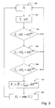
- Fig. 1 shows the time evolution of the setpoint values for the active power to be injected in a transfer point of the wind farm.
- the target values are calculated according to one of the prior art methods. In this case, the situation may arise that for the wind farm the maximum power increase is defined for a time interval of 10 minutes. So if the wind farm can cope with the increase in performance in less than 10 minutes, then the Fig. 1 on the stairs.
- the setpoint of which is represented by the triangles the line 12 shows an approximately linear increase of the setpoint curve. The jump at the beginning of the curve 12 shortly after the start of the wind farm is created by an additional offset, which will be explained in more detail below. Curve 12 is characterized in that paragraphs of the setpoint curve are avoided.
- Fig. 2 shows in a block diagram the calculation of the setpoint values for wind turbines WEA 1, WEA 2 to WEA n.
- 14 different setpoint suggestions 16 to 20 are applied to a setpoint selection and a controller 14.
- the setpoint suggestions are generated by individual setpoint generators 22 to 26. This refers to the Setpoint generator 1 not to a setpoint for the first wind turbine, but rather to a setpoint for the entire wind farm, taking into account a first time interval.
- a first time interval, a second time interval and with the setpoint generator 26 a third time interval are considered.
- each setpoint generator is the current value of the active power 28 at. Furthermore, there is a gradient setpoint at each setpoint generator 22 to 26.
- the gradient setpoints 30 to 34 in each case predetermine the maximum permissible increase for the mean value of the corresponding time interval. Thus, for example, gradient setpoint 1 predetermines a value of 3.0 MW per 1-minute average value, while gradient setpoint value 2 predetermines a value of 20 MW per 10-minute average value.
- Each setpoint generator 22 to 26 calculates a setpoint suggestion that indicates a setpoint value of the entire wind farm for a corresponding time interval.
- the smallest value is selected by the desired value suggestions 16, 18, 20.
- the target values for the individual wind energy plants are determined in addition to the selected target value for the wind farm. In this case, the actual values of the individual wind turbines (not shown) are taken into account so as to determine desired values for the individual wind turbines.
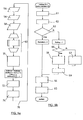
- Fig. 3 shows by way of example the sequence of the method according to the invention for operating a wind farm.
- the wind farm is operated by a parking control with a setpoint value for an active power P S 100. If the wind refreshes, the setpoint P S for the active power can be significantly higher than the current actual value of the active power. As a result, the active power in the wind farm is rapidly increased.
- the average increase in the actual values of the active power ⁇ P i in method step 102 is calculated.
- a setpoint suggestion V i is calculated in step 110 for each time interval.
- the calculation of the desired value proposed value V i is carried out starting from the middle desired value P i in the time interval T i plus the maximum value for the change of the active power in the time interval ⁇ P i max multiplied by a gradient factor f grad .
- a new setpoint value P s is calculated under method step 112. The new set point P s results as the minimum of all setpoint suggestions.
- the method ensures that, when the wind farm is increased in power, the maximum values ⁇ P i max defined for the time intervals are not exceeded, but at the same time there is a steady increase in performance which avoids jumps and kinks in the increase in power.
- Fig. 4 shows a setpoint generator in detail.
- this corresponds to one of the desired value formers 22, 24 or 26 Fig. 2 , is the actual value of the active power 28 and a gradient setpoint 40 at.
- a mean value for the time interval for which the setpoint generator 38 is provided is determined in a first step 42.
- the applied gradient target value 40 is additionally multiplied by a gradient factor 44 and the mean value formed is added to the product in 46.
- the output of the setpoint generator 38 is then a setpoint suggestion 48.
- An average gradient 50 is calculated from the mean value 42 formed.
- the mean gradient is the change in the mean over the considered time interval.
- the offset function 52 is then formed.
- the result of the offset function 52 is added together with the result of the multiplication with the gradient factor 44 in step 46 and thus together forms the setpoint suggestion 48.
- the determination of the offset function is in the FIGS. 5 to step 60 described in detail.
- Fig. 5a shows the inventive method in the overall process flow.
- the parameters of the method are read.
- the actual values of the power and in step 58 the target power values are read by the RU.
- the maximum gradient setpoints specified by the RU are also read.
- a subsequent step 60 for each of the considered Time intervals 1 to n each formed a setpoint suggestion.
- the formation of the setpoint is in Fig. 5b shown in detail.
- the mean value over the considered time interval is formed in step 61.
- the actual value of the increase for the time interval is determined from the mean value formed for the time interval.
- step 63 a query is made as to whether the actual value of the gradient for the predetermined time interval is less than a predefined start value or whether a start offset is greater than zero.
- an init flag is set and the gradient offset is calculated in step 64 from the setpoint gradient multiplied by the gradient factor.
- the new setpoint proposal for the time interval then results in step 65 from the mean value plus the precalculated gradient offset for the time interval.
- the start offset for the time interval is additionally added in step 65, which is, however, equal to zero in the case under consideration.
- a start phase is present.
- a start offset is additionally calculated for the calculation of the desired value proposed in step 65.
- the start offset for the time interval is formed from the setpoint gradient multiplied by a start offset factor for the time interval. If a first calculation of the starting offset is not carried out, the start offset from the previous pass is reduced in step 68. For this purpose, a specific value is subtracted from the start offset.
- the value to be subtracted results from the setpoint gradient multiplied by the starting offset factor for the time interval considered divided by a decay number for the time interval.
- the reduction step 68 causes the value of the starting offset for the time interval to be gradually reduced over time.
- step 69 ensures that no negative start offset is used in the further course.
- the calculation of the starting offset is carried out by the method steps 64 and 65, wherein now additionally a value for the start offset for the setpoint proposed value is calculated in method step 65.
- method step 70 the minimum of the setpoint suggestions calculated in method step 60 is formed.
- setpoint specifications for limiting the wind farm are also taken into account by the RU.
- the manipulated variable for the wind farm is determined by performing a desired actual value comparison.
- a subsequent step 74 follows a distribution of the manipulated variables from the wind farm to individual wind turbines. The individual wind turbines then regulate independently of each other to their specified setpoint. Via the branch 76, the method returns to its initial state and is then repeated cyclically.
Abstract
Description
Die vorliegende Erfindung betrifft ein Verfahren zum Betrieb eines Windparks mit zwei oder mehr Windenergieanlagen.The present invention relates to a method for operating a wind farm with two or more wind turbines.
Für den Anschluss von Windparks an das elektrische Versorgungsnetz existiert eine Vielzahl von unterschiedlichen Netzanschlussrichtlinien, die teilweise Anforderungen an und Begrenzungen für die eingespeiste Leistung enthalten. Bei den Leistungsanforderungen können auch sogenannte Anstiegsbegrenzungen vorgesehen sein, die einem Windpark vorgeben, in welchem Maße die eingespeiste Leistung erhöht oder erniedrigt werden darf. Konkret bedeutet dies, dass, wenn der Windpark startet oder das Windangebot steigt, die Leistung nicht so schnell steigen darf, wie es technisch für den Windpark möglich ist, sondern über eine oder mehrere Anstiegsrampen begrenzt werden muss. In einem konkreten Fall kann dies beispielsweise maximal 3,0 MW/Min und maximal 20 MW/10 Min sein, wobei sich der Anstieg von 3,0 MW pro Minute auf den über eine Minute gemittelten Wert bezieht, ebenso wie der Anstieg von 20 Megawatt sich auf den 10 Minuten Mittelwert bezieht. Dies bedeutet, dass in einer Minute der maximale Leistungsanstieg des Windparks 3,0 Megawatt betragen darf, aber gleichzeitig in einem Zeitraum von 10 Minuten die Leistungserhöhung nicht mehr als 20 Megawatt betragen darf.There are a number of different grid connection guidelines for the connection of wind farms to the electricity grid, some of which contain requirements and limits for the fed-in power. In the power requirements and so-called increase limits can be provided, which dictate a wind farm, to which extent the injected power may be increased or decreased. Specifically, this means that when the wind farm starts or the wind supply increases, the power must not rise as fast as technically possible for the wind farm, but must be limited by one or more ramps. In a specific case, for example, this may be a maximum of 3.0 MW / min and a maximum of 20 MW / 10 min, with the increase of 3.0 MW per minute relating to the value averaged over one minute, as well as the increase of 20 megawatts refers to the 10 minute average. This means that in one minute the maximum power increase of the wind farm may be 3.0 megawatts, but at the same time in a 10-minute period the power increase may not exceed 20 megawatts.
Aus
Aus
Der Erfindung liegt die Aufgabe zugrunde, ein Verfahren zum Betrieb eines Windparks bereitzustellen, bei dem eine Parksteuerung einen Sollwert für eine zu erzeugende elektrische Größe des Windparks so vorgibt, dass eine kontinuierliche Erhöhung der elektrischen Größe erfolgt und eine treppenförmige oder mit Knicken versehene Erhöhung der elektrischen Größe vermieden wird.The invention has for its object to provide a method for operating a wind farm, in which a parking control sets a target value for an electrical variable of the wind farm to be generated so that there is a continuous increase in electrical size and a stepped or kinked increase in electrical Size is avoided.
Erfindungsgemäß wird die Aufgabe durch ein Verfahren mit den Merkmalen aus Anspruch 1 gelöst. Vorteilhafte Ausgestaltungen bilden die Gegenstände der Unteransprüche.According to the invention the object is achieved by a method having the features of
Das erfindungsgemäße Verfahren dient zum Betrieb eines Windparks mit zwei oder mehr Windenergieanlagen. Der Windpark weist eine Parksteuerung auf, die einen Sollwert für eine zu erzeugende elektrische Größe des Windparks vorgibt. Bei dem erfindungsgemäßen Verfahren berechnet die Parksteuerung fortlaufend eine mittlere Steigerung der Istwerte der elektrischen Größe für mindestens ein Zeitintervall. Ferner vergleicht die Parksteuerung die berechnete mittlere Steigerung der Istwerte für ein Zeitintervall, mit einem Maximalwert für die Steigerung der elektrischen Größe in dem entsprechenden Zeitintervall. Bei dem erfindungsgemäßen Verfahren kommen ein, zwei oder mehr Zeitintervalle zum Einsatz, für die fortlaufend die mittlere Steigerung berechnet wird und ein Maximalwert der Steigerung definiert ist. Die Parksteuerung bestimmt einen neuen Sollwert der elektrischen Größe des Windparks, wenn die mittleren Steigerungen kleiner als der Maximalwert sind. Im Fall, wenn mehrere Zeitintervalle betrachtet werden, wird ein neuer Sollwert dann bestimmt, wenn sämtliche mittlere Steigerungen kleiner als die zugehörigen Maximalwerte in dem Zeitintervall sind. Für den Fall, dass die mittlere Steigerung in einem Zeitintervall bereits größer als der Maximalwert für die Steigerung in einem Zeitintervall ist, ist es nicht notwendig, einen neuen Sollwert zu bestimmen, da der Windpark mit seiner Änderung bereits den Maximalwert für die Steigerung der elektrischen Größe überschritten hat. Der neue Sollwert der elektrischen Größe des Windparks wird erfindungsgemäß aus einer Sollwertauswahl als Minimum von mehreren Sollwertvorschlägen bestimmt. Die Sollwertvorschläge werden von der Parksteuerung einzeln für jedes in Betracht gezogene Zeitintervall ermittelt. Dabei wird für jedes Zeitintervall ausgehend von den fortlaufend über das Zeitintervall gemittelten Istwerten der elektrischen Größe ein Sollwertvorschlag ermittelt. Der Sollwertvorschlag für ein Zeitintervall wird aus den über das Zeitintervall gemittelten Istwerten zuzüglich des mit dem Gradientenfaktor multiplizierten Maximalwertes für die Steigerung der elektrischen Größe in dem Zeitintervall bestimmt, wobei der Gradientenfaktor größer null und kleiner eins ist. Der Gradientenfaktor berücksichtigt hierbei, dass, wenn der Maximalwert für die Steigerung der elektrischen Größe vollständig addiert würde, über das Zeitintervall sich eine größere Steigerung ergäbe. Der Gradientenfaktor kleiner als eins stellt somit sicher, dass eine in dem Zeitintervall mehrfach wiederholte Addition des Maximalwerts für die Steigerung nicht zu einer zu starken Erhöhung des Istwerts führt.The inventive method is used to operate a wind farm with two or more wind turbines. The wind farm has a park control, which specifies a target value for an electrical variable of the wind farm to be generated. In the method according to the invention, the parking control continuously calculates an average increase in the actual values of the electrical variable for at least one time interval. Further, the parking controller compares the calculated average increase of the actual values for a time interval with a maximum value for the increase of the electrical quantity in the corresponding time interval. In the method according to the invention For example, one, two or more time intervals are used for which the average increase is continuously calculated and a maximum value of the increase is defined. The park control determines a new setpoint of the electrical size of the wind farm when the average increases are less than the maximum value. In the case where a plurality of time intervals are considered, a new set point is determined when all mean increases are smaller than the associated maximum values in the time interval. In the event that the mean increase in a time interval is already greater than the maximum value for the increase in a time interval, it is not necessary to determine a new set value, since the wind farm with its change already the maximum value for increasing the electrical size has exceeded. The new setpoint of the electrical variable of the wind farm is inventively determined from a setpoint selection as a minimum of several setpoint suggestions. The setpoint suggestions are determined by the parking controller individually for each time interval considered. In this case, a setpoint suggestion is determined for each time interval on the basis of the actual values of the electrical variable that are continuously averaged over the time interval. The setpoint proposal for a time interval is determined from the actual values averaged over the time interval plus the maximum factor multiplied by the gradient factor for the increase of the electrical quantity in the time interval, wherein the gradient factor is greater than zero and less than one. The gradient factor hereby takes into account that if the maximum value for the increase of the electrical quantity were to be completely added, there would be a greater increase over the time interval. The gradient factor smaller than one thus ensures that an addition of the maximum value for the increase repeated several times in the time interval does not lead to an excessive increase of the actual value.
Bei dem erfindungsgemäßen Verfahren wird, um einen kontinuierlichen Anstieg der Sollwerte der elektrischen Größe zu erreichen und gleichzeitig die vorgegebenen Maximalwerte einzuhalten bei der Ermittlung des Sollwertvorschlags auf einen fortlaufend über das betrachtete Zeitintervall ermittelten Istwert abgestellt. Der Erfindung liegt die Erkenntnis zugrunde, dass mit der Verwendung des fortlaufend über den Zeitwert gemittelten Istwerts vermieden werden kann, dass eine stufenförmige Erhöhung der Sollwerte auftritt oder dass die Sollwerte Absätze bilden. Das erfindungsgemäße Verfahren führt zu einem kontinuierlichen Anstieg der Sollwerte.In the method according to the invention, in order to achieve a continuous increase in the setpoint values of the electrical variable and at the same time to comply with the predetermined maximum values, the value of the desired value is determined in a continuous manner over the considered time interval. The invention is based on the finding that with the use of the actual value, which is continuously averaged over the time value, it can be avoided that a step-shaped increase of the setpoint values occurs or that the setpoint values constitute steps. The method according to the invention leads to a continuous increase of the nominal values.
In einer bevorzugten Ausgestaltung können als weitere Sollwertvorschläge auch extern an der Parksteuerung anliegende Werte für eine maximale zulässige Änderung der elektrischen Größe bei der Sollwertzahl berücksichtigt werden. Indem bei der Sollwertauswahl stets das Minimum der Sollwertvorschläge berücksichtigt wird, können die beispielsweise von einem durch die Versorgungsunternehmen kurzfristig bestimmten begrenzten Anstiege der elektrischen Größe mitberücksichtigt werden.In a preferred embodiment, as further setpoint suggestions, values applied externally to the parking control for a maximum permissible change in the electrical variable in the setpoint number can also be taken into account. By always taking into account the minimum of the set point proposals in the setpoint selection, the, for example, of a short term determined by the utilities limited increases in electrical size can be taken into account.
In einer weiteren bevorzugten Ausgestaltung teilt die Windparksteuerung zusätzlich den Sollwert für die elektrische Größe des Windparks auf die mindestens zwei Windenergieanlagen auf. Bei der Aufteilung der Sollwerte für den Windpark auf die einzelnen Windenergieanlagen wird bevorzugt der Istwert der elektrischen Größe der einzelnen Windenergieanlage berücksichtigt. Auf diese Weise kann sichergestellt werden, dass einer Windenergieanlage im Windpark, deren elektrische Größe sich beispielsweise bereits in der Nähe des Nennbereichs der Windenergieanlage befindet, nicht ein über den Nennbereich hinaus erhöhter Sollwert vorgegeben wird.In a further preferred refinement, the wind farm control additionally allocates the desired value for the electrical variable of the wind farm to the at least two wind turbines. When distributing the setpoint values for the wind farm to the individual wind energy plants, the actual value of the electrical variable of the individual wind energy plant is preferably taken into account. In this way it can be ensured that a wind energy plant in the wind farm whose electrical size is already close to the rated range of the wind energy plant, for example, is not given a desired value which is higher than the nominal area.
In einer bevorzugten Ausgestaltung ist der Gradientenfaktor eine zeitlich konstante Größe. Auch ist es möglich, den Gradientenfaktor abhängig von der Länge des Zeitintervalls, das betrachtet wird, zu wählen.In a preferred embodiment, the gradient factor is a constant quantity over time. It is also possible to choose the gradient factor as a function of the length of the time interval considered.
Bei dem erfindungsgemäßen Verfahren können für die elektrische Größe des Windparks verschiedene Größen betrachtet werden. So ist es möglich, auf eine Wirkleistung, eine Blindleistung, einen Leistungsfaktor, einen Phasenwinkel, eine Frequenz oder eine Spannung in einem Übergabepunkt zwischen Windpark und elektrischem Versorgungsnetz abzustellen. Auch ist es möglich, Kombinationen dieser Größen zu betrachten.In the method according to the invention, different sizes can be considered for the electrical size of the wind farm. It is thus possible to switch off to an active power, a reactive power, a power factor, a phase angle, a frequency or a voltage in a transfer point between the wind farm and the electrical supply network. It is also possible to consider combinations of these sizes.
Bei dem erfindungsgemäßen Verfahren wird zur Berechnung eines Sollwertvorschlags auf eine fortlaufend gemittelte Istwertgröße abgestellt. Dadurch können bei einer Leistungserhöhung des Windparks Absätze und Knicke in den Sollwerten vermieden werden. Bei diesem Ansatz ist es zweckmäßig, dass in einer Anfangsphase des Betriebes des Windparks, in der die Windenergieanlagen die erzeugte elektrische Größe gegenüber einem quasistationären Zustand oder einem heruntergefahrenen Zustand erhöhen, also noch keine zurückliegenden Istwerte vorliegen oder diese noch nicht für das gesamte betrachtete Zeitintervall vorliegen, zu den Sollwertvorschlägen für das Zeitintervall jeweils ein Offset hinzu addiert wird. Dieser Offset in der Anfangsphase des Betriebes des Windparks stellt sicher, dass beim Hochfahren der Sollwerte keine zu starke Verzögerung des Mittelwerts auftritt. In einer bevorzugten Ausgestaltung ist vorgesehen, dass der Offset mit zunehmender Zeitdauer seit Beginn der Anfangsphase abnimmt.In the method according to the invention, the calculation of a setpoint proposed value is based on a continuously averaged actual value variable. As a result, paragraphs and kinks in the nominal values can be avoided when the wind farm increases its output. In this approach, it is expedient that in an initial phase of the operation of the wind farm, in which the wind turbines increase the electrical quantity generated compared to a quasi-stationary state or a shut down state, so there are no past actual values or they are not present for the entire time interval considered , an offset is added to the setpoint proposals for the time interval. This offset in the initial phase of the operation of the wind farm ensures that when the setpoints are raised, the average value is not delayed too much. In a preferred embodiment, it is provided that the offset decreases with increasing duration since the beginning of the initial phase.
Eine bevorzugte Ausgestaltung des erfindungsgemäßen Verfahrens wird nachfolgend an einem Beispiel näher erläutert. Es zeigt:
- Fig. 1
- die von einem Windpark bereitgestellte Wirkleistung in Megawatt über der Zeit, einmal für das erfindungsgemäße Verfahren und einmal für ein Verfahren aus dem Stand der Technik,
- Fig. 2
- ein Blockdiagramm zur Bestimmung der Sollwerte der einzelnen Windenergieanlagen,
- Fig. 3
- ein Flussdiagramm zu dem erfindungsgemäßen Verfahren,
- Fig. 4
- ein Blockdiagramm zu einem Sollwertbildner und
- Fign. 5a und b
- jeweils ein Ablaufdiagramm für das erfindungsgemäße Verfahren.
- Fig. 1
- the real power in megawatts over time provided by a wind farm, once for the method according to the invention and once for a method from the prior art,
- Fig. 2
- a block diagram for determining the nominal values of the individual wind turbines,
- Fig. 3
- a flow chart of the method according to the invention,
- Fig. 4
- a block diagram to a setpoint generator and
- FIGS. 5a and b
- each a flowchart for the inventive method.
An jedem Sollwertbildner liegt der aktuelle Wert der Wirkleistung 28 an. Ferner liegt an jedem Sollwertbildner 22 bis 26 ein Gradientensollwert an. Die Gradientensollwerte 30 bis 34 geben dabei jeweils den maximal zulässigen Anstieg für den Mittelwert des entsprechenden Zeitintervalls vor. Gradientensollwert 1 gibt also beispielsweise einen Wert von 3,0 MW pro 1-Minuten-Mittelwert vor, während Gradientensollwert 2 einen Wert von 20 MW pro 10-Minuten-Mittelwert vorgibt. Jeder Sollwertbildner 22 bis 26 berechnet einen Sollwertvorschlag, der für ein entsprechendes Zeitintervall einen Sollwert des gesamten Windparks angibt.At each setpoint generator is the current value of the
In der Sollwertauswahl 14 und dem dazugehörigen Regler wird von den Sollwertvorschlägen 16, 18, 20 der kleinste Wert ausgewählt. In einem weiteren Schritt werden außer dem ausgewählten Sollwert für den Windpark die Sollwerte für die einzelnen Windenergieanlagen bestimmt. Hierbei werden die Istwerte der einzelnen Windenergieanlagen (nicht dargestellt) berücksichtigt, um so Sollwerte für die einzelnen Windenergieanlagen zu bestimmen.In the desired
Bei der Ermittlung des Sollwerts für den Windpark ausgehend von den Sollwertvorschlägen 16, 18, 20 können auch weitere Sollwertlimitierungen 36 bei der Sollwertauswahl berücksichtigt werden. So ist es beispielsweise möglich, dass ein Energieversorgungsunternehmen der Parksteuerung des Windparks zusätzlich Sollwertlimitierungen 36 vorgibt, die bei Auswahl der Sollwerte berücksichtigt werden.When determining the setpoint value for the wind farm on the basis of the
Für den Fall, dass in sämtlichen Zeitintervallen Ti die mittlere Steigerung der Wirkleistung in dem Zeitintervall unterhalb der maximal zulässigen Steigerung liegt, wird in Verfahrensschritt 110 für jedes Zeitintervall ein Sollwertvorschlag Vi berechnet. Die Berechnung des Sollwertvorschlags Vi erfolgt ausgehend von dem mittleren Sollwert
Mit dem Verfahren wird sichergestellt, dass bei einer Leistungssteigerung des Windparks die für die Zeitintervalle definierten Maximalwerte ΔPi max nicht überschritten werden, gleichzeitig aber eine stetige Leistungssteigerung erfolgt, die Sprünge und Knicke bei der Leistungssteigerung vermeidet.The method ensures that, when the wind farm is increased in power, the maximum values ΔP i max defined for the time intervals are not exceeded, but at the same time there is a steady increase in performance which avoids jumps and kinks in the increase in power.
Wird dagegen bei Abfrage 63 festgestellt, dass eine der Bedingungen erfüllt ist, so liegt eine Startphase vor. In der Startphase wird zusätzlich ein Startoffset für die Berechnung des Sollwertvorschlags in Schritt 65 berechnet. Hierzu wird in Schritt 66 zunächst überprüft, ob eine erste Berechnung des Startoffsets erfolgt, indem das Initflag abgefragt wird. In diesem Fall wird in Schritt 67 der Startoffset für das Zeitintervall aus dem Sollwertgradienten multipliziert mit einem Startoffsetfaktor für das Zeitintervall gebildet. Erfolgt nicht eine erste Berechnung des Startoffsets, so wird der Startoffset aus dem vergangenen Durchlauf in Schritt 68 reduziert. Hierzu wird von dem Startoffset ein bestimmter Wert abgezogen. Der abzuziehende Wert ergibt sich aus dem Sollwertgradient multipliziert mit dem Startoffsetfaktor für das betrachtete Zeitintervall dividiert durch eine Abklingzahl für das Zeitintervall. Im Ergebnis führt der Verminderungsschritt 68 dazu, dass im Laufe der Zeit der Wert des Startoffsets für das Zeitintervall schrittweise reduziert wird. In einem nachfolgenden Schritt 69 wird sichergestellt, dass kein negativer Startoffset im weiteren Ablauf verwendet wird. Die Berechnung des Startoffsets erfolgt durch die Verfahrensschritte 64 und 65, wobei nun in dem Verfahrensschritt 65 zusätzlich ein Wert für den Startoffset für den Sollwertvorschlag berechnet wird.If, on the other hand, it is determined in
In Verfahrensschritt 70 wird das Minimum der in Verfahrensschritt 60 berechneten Sollwertvorschläge gebildet. Hierbei werden auch Sollwertvorgaben zur Begrenzung des Windparks von dem EVU berücksichtigt. In einem nachfolgenden Schritt 72 wird die Stellgröße für den Windpark ermittelt, indem ein Soll-Istwertvergleich durchgeführt wird. In einem nachfolgenden Schritt 74 folgt eine Verteilung der Stellgrößen aus dem Windpark auf einzelne Windenergieanlagen. Die einzelnen Windenergieanlagen regeln dann unabhängig voneinander auf den ihnen vorgegebenen Sollwert. Über den Ast 76 kehrt das Verfahren zu seinem Ausgangszustand zurück und wird dann zyklisch wiederholt.In
Claims (9)
Applications Claiming Priority (1)
| Application Number | Priority Date | Filing Date | Title |
|---|---|---|---|
| DE102009006671.3A DE102009006671B4 (en) | 2009-01-29 | 2009-01-29 | Method for operating a wind farm |
Publications (3)
| Publication Number | Publication Date |
|---|---|
| EP2213874A2 true EP2213874A2 (en) | 2010-08-04 |
| EP2213874A3 EP2213874A3 (en) | 2013-08-14 |
| EP2213874B1 EP2213874B1 (en) | 2015-04-01 |
Family
ID=42174587
Family Applications (1)
| Application Number | Title | Priority Date | Filing Date |
|---|---|---|---|
| EP10000849.9A Active EP2213874B1 (en) | 2009-01-29 | 2010-01-28 | Method for operating a wind farm |
Country Status (3)
| Country | Link |
|---|---|
| US (1) | US8190300B2 (en) |
| EP (1) | EP2213874B1 (en) |
| DE (1) | DE102009006671B4 (en) |
Cited By (1)
| Publication number | Priority date | Publication date | Assignee | Title |
|---|---|---|---|---|
| EP2824791A1 (en) * | 2013-05-28 | 2015-01-14 | Siemens Aktiengesellschaft | Method and system for limitation of power output variation in variable generation renewable facilities |
Families Citing this family (3)
| Publication number | Priority date | Publication date | Assignee | Title |
|---|---|---|---|---|
| DE102008028568A1 (en) * | 2008-06-16 | 2009-12-31 | Nordex Energy Gmbh | Method for controlling a wind energy plant |
| DE102015218472A1 (en) | 2015-09-25 | 2017-03-30 | Siemens Aktiengesellschaft | Method and device for operating a technical system |
| US10968890B2 (en) | 2015-12-10 | 2021-04-06 | Vestas Wind Systems A/S | Controlling wind turbine power production within power ramp rate limit for wind power plant |
Citations (2)
| Publication number | Priority date | Publication date | Assignee | Title |
|---|---|---|---|---|
| EP1672779A2 (en) | 2004-12-17 | 2006-06-21 | General Electric Company | Wind farm power ramp rate control system and method |
| US20070173982A1 (en) | 2006-01-26 | 2007-07-26 | General Electric Company | Systems and methods for controlling a ramp rate of a wind farm |
Family Cites Families (9)
| Publication number | Priority date | Publication date | Assignee | Title |
|---|---|---|---|---|
| PL212009B1 (en) * | 2001-09-28 | 2012-07-31 | Aloys Wobben | Method for operating a wind park |
| JP2005312138A (en) | 2004-04-19 | 2005-11-04 | Canon Inc | Power controller, power generation system and power system |
| US7298059B2 (en) * | 2004-12-17 | 2007-11-20 | General Electric Company | System and method for operating a wind farm under high wind speed conditions |
| US7199482B2 (en) * | 2005-06-30 | 2007-04-03 | General Electric Company | System and method for controlling effective wind farm power output |
| US7536240B2 (en) * | 2005-07-22 | 2009-05-19 | Ut-Battelle, Llc | Real power regulation for the utility power grid via responsive loads |
| US20070055392A1 (en) * | 2005-09-06 | 2007-03-08 | D Amato Fernando J | Method and system for model predictive control of a power plant |
| US20070124025A1 (en) * | 2005-11-29 | 2007-05-31 | General Electric Company | Windpark turbine control system and method for wind condition estimation and performance optimization |
| US7826908B2 (en) * | 2007-11-02 | 2010-11-02 | Emerson Process Management Power & Water Solutions, Inc. | Variable rate feedforward control based on set point rate of change |
| US8901411B2 (en) * | 2008-08-27 | 2014-12-02 | General Electric Company | System and method for controlling ramp rate of solar photovoltaic system |
-
2009
- 2009-01-29 DE DE102009006671.3A patent/DE102009006671B4/en not_active Expired - Fee Related
- 2009-05-04 US US12/435,070 patent/US8190300B2/en active Active
-
2010
- 2010-01-28 EP EP10000849.9A patent/EP2213874B1/en active Active
Patent Citations (2)
| Publication number | Priority date | Publication date | Assignee | Title |
|---|---|---|---|---|
| EP1672779A2 (en) | 2004-12-17 | 2006-06-21 | General Electric Company | Wind farm power ramp rate control system and method |
| US20070173982A1 (en) | 2006-01-26 | 2007-07-26 | General Electric Company | Systems and methods for controlling a ramp rate of a wind farm |
Cited By (1)
| Publication number | Priority date | Publication date | Assignee | Title |
|---|---|---|---|---|
| EP2824791A1 (en) * | 2013-05-28 | 2015-01-14 | Siemens Aktiengesellschaft | Method and system for limitation of power output variation in variable generation renewable facilities |
Also Published As
| Publication number | Publication date |
|---|---|
| EP2213874B1 (en) | 2015-04-01 |
| US8190300B2 (en) | 2012-05-29 |
| DE102009006671A1 (en) | 2010-08-05 |
| US20100191384A1 (en) | 2010-07-29 |
| DE102009006671B4 (en) | 2015-09-10 |
| EP2213874A3 (en) | 2013-08-14 |
Similar Documents
| Publication | Publication Date | Title |
|---|---|---|
| EP2333926B1 (en) | Wind farm and method for operating a wind farm | |
| EP2028368A2 (en) | Wind farm with a number of wind plants and method for operating a wind farm | |
| EP2632012B1 (en) | Method for synchronising a feed-in voltage with a mains voltage | |
| DE102006039693A1 (en) | Method for operating wind turbines | |
| EP2244348A2 (en) | Wind farm with multiple wind energy assemblies and method for regulating the feed-in from a wind farm | |
| DE102013208410A1 (en) | Method for feeding electrical power into an electrical supply network | |
| EP2213874B1 (en) | Method for operating a wind farm | |
| WO2015067408A1 (en) | Method for operating a wind turbine | |
| EP2875560B1 (en) | Method for controlling the ratio between supplied and drawn electric energy in an electric energy supply network | |
| EP2066017B1 (en) | Method of operating a wind energy system with a voltage-dependent control for an electric reactive quantity to be provided | |
| DE102012101928A1 (en) | Power grid decentralized stabilizing method, involves minimizing feed-in power of power grid decentralized stabilizing system in relation to actual maximum generator power according with requirements for feed-in power | |
| EP3772584A1 (en) | Wind farm control | |
| WO2013152788A1 (en) | Electric device, and method for controlling an electric energy generator | |
| EP2226500B1 (en) | Wind farm regulator | |
| WO2015039802A1 (en) | Method for the computer-aided control of one or more regenerative energy production installations in an electrical power supply system | |
| EP1903656B1 (en) | Method for primary control for a joint electricity network | |
| DE102014010019A1 (en) | Method for switching decentralized energy converters | |
| DE102019214132A1 (en) | Method for operating a network management system for a local energy network as a function of a storage strategy of an energy store, as well as a network management system | |
| EP0861366A2 (en) | Method and device for rapid output adjustment of a power-generating facility | |
| WO2011085961A2 (en) | Method and device for synchronizing a generator in a network | |
| DE102019101048A1 (en) | Wind turbine for feeding electrical power into an electrical supply network | |
| EP2677622B1 (en) | Method and a device for feeding electrical power to an electrical energy supply network | |
| EP3425197B1 (en) | Power reduction in multiple wind energy assemblies in a wind farm | |
| DE102020134772A1 (en) | METHOD OF OPERATING AN ENERGY SUPPLY PLANT, PLANT CONTROLLER FOR AN ENERGY SUPPLY PLANT, AND ENERGY SUPPLY PLANT | |
| DE102010014719A1 (en) | Method for determining design parameters of wind-power plant, involves forming mean value over time-steps of total wind power and setting mean value to power rating of plant for producing basic design wind speed |
Legal Events
| Date | Code | Title | Description |
|---|---|---|---|
| PUAI | Public reference made under article 153(3) epc to a published international application that has entered the european phase |
Free format text: ORIGINAL CODE: 0009012 |
|
| AK | Designated contracting states |
Kind code of ref document: A2 Designated state(s): AT BE BG CH CY CZ DE DK EE ES FI FR GB GR HR HU IE IS IT LI LT LU LV MC MK MT NL NO PL PT RO SE SI SK SM TR |
|
| AX | Request for extension of the european patent |
Extension state: AL BA RS |
|
| PUAL | Search report despatched |
Free format text: ORIGINAL CODE: 0009013 |
|
| AK | Designated contracting states |
Kind code of ref document: A3 Designated state(s): AT BE BG CH CY CZ DE DK EE ES FI FR GB GR HR HU IE IS IT LI LT LU LV MC MK MT NL NO PL PT RO SE SI SK SM TR |
|
| AX | Request for extension of the european patent |
Extension state: AL BA RS |
|
| RIC1 | Information provided on ipc code assigned before grant |
Ipc: F03D 7/02 20060101ALI20130709BHEP Ipc: F03D 7/04 20060101AFI20130709BHEP |
|
| 17P | Request for examination filed |
Effective date: 20140128 |
|
| RBV | Designated contracting states (corrected) |
Designated state(s): AT BE BG CH CY CZ DE DK EE ES FI FR GB GR HR HU IE IS IT LI LT LU LV MC MK MT NL NO PL PT RO SE SI SK SM TR |
|
| GRAP | Despatch of communication of intention to grant a patent |
Free format text: ORIGINAL CODE: EPIDOSNIGR1 |
|
| INTG | Intention to grant announced |
Effective date: 20141205 |
|
| GRAS | Grant fee paid |
Free format text: ORIGINAL CODE: EPIDOSNIGR3 |
|
| GRAA | (expected) grant |
Free format text: ORIGINAL CODE: 0009210 |
|
| AK | Designated contracting states |
Kind code of ref document: B1 Designated state(s): AT BE BG CH CY CZ DE DK EE ES FI FR GB GR HR HU IE IS IT LI LT LU LV MC MK MT NL NO PL PT RO SE SI SK SM TR |
|
| RAP1 | Party data changed (applicant data changed or rights of an application transferred) |
Owner name: NORDEX ENERGY GMBH |
|
| REG | Reference to a national code |
Ref country code: GB Ref legal event code: FG4D Free format text: NOT ENGLISH |
|
| REG | Reference to a national code |
Ref country code: CH Ref legal event code: EP |
|
| REG | Reference to a national code |
Ref country code: IE Ref legal event code: FG4D Free format text: LANGUAGE OF EP DOCUMENT: GERMAN |
|
| REG | Reference to a national code |
Ref country code: DE Ref legal event code: R096 Ref document number: 502010009211 Country of ref document: DE Effective date: 20150513 |
|
| REG | Reference to a national code |
Ref country code: AT Ref legal event code: REF Ref document number: 719246 Country of ref document: AT Kind code of ref document: T Effective date: 20150515 |
|
| REG | Reference to a national code |
Ref country code: SE Ref legal event code: TRGR |
|
| REG | Reference to a national code |
Ref country code: NL Ref legal event code: VDEP Effective date: 20150401 |
|
| REG | Reference to a national code |
Ref country code: LT Ref legal event code: MG4D |
|
| PG25 | Lapsed in a contracting state [announced via postgrant information from national office to epo] |
Ref country code: NL Free format text: LAPSE BECAUSE OF FAILURE TO SUBMIT A TRANSLATION OF THE DESCRIPTION OR TO PAY THE FEE WITHIN THE PRESCRIBED TIME-LIMIT Effective date: 20150401 |
|
| PG25 | Lapsed in a contracting state [announced via postgrant information from national office to epo] |
Ref country code: NO Free format text: LAPSE BECAUSE OF FAILURE TO SUBMIT A TRANSLATION OF THE DESCRIPTION OR TO PAY THE FEE WITHIN THE PRESCRIBED TIME-LIMIT Effective date: 20150701 Ref country code: CZ Free format text: LAPSE BECAUSE OF FAILURE TO SUBMIT A TRANSLATION OF THE DESCRIPTION OR TO PAY THE FEE WITHIN THE PRESCRIBED TIME-LIMIT Effective date: 20150401 Ref country code: PT Free format text: LAPSE BECAUSE OF FAILURE TO SUBMIT A TRANSLATION OF THE DESCRIPTION OR TO PAY THE FEE WITHIN THE PRESCRIBED TIME-LIMIT Effective date: 20150803 Ref country code: ES Free format text: LAPSE BECAUSE OF FAILURE TO SUBMIT A TRANSLATION OF THE DESCRIPTION OR TO PAY THE FEE WITHIN THE PRESCRIBED TIME-LIMIT Effective date: 20150401 Ref country code: LT Free format text: LAPSE BECAUSE OF FAILURE TO SUBMIT A TRANSLATION OF THE DESCRIPTION OR TO PAY THE FEE WITHIN THE PRESCRIBED TIME-LIMIT Effective date: 20150401 Ref country code: HR Free format text: LAPSE BECAUSE OF FAILURE TO SUBMIT A TRANSLATION OF THE DESCRIPTION OR TO PAY THE FEE WITHIN THE PRESCRIBED TIME-LIMIT Effective date: 20150401 Ref country code: FI Free format text: LAPSE BECAUSE OF FAILURE TO SUBMIT A TRANSLATION OF THE DESCRIPTION OR TO PAY THE FEE WITHIN THE PRESCRIBED TIME-LIMIT Effective date: 20150401 |
|
| PG25 | Lapsed in a contracting state [announced via postgrant information from national office to epo] |
Ref country code: LV Free format text: LAPSE BECAUSE OF FAILURE TO SUBMIT A TRANSLATION OF THE DESCRIPTION OR TO PAY THE FEE WITHIN THE PRESCRIBED TIME-LIMIT Effective date: 20150401 Ref country code: IS Free format text: LAPSE BECAUSE OF FAILURE TO SUBMIT A TRANSLATION OF THE DESCRIPTION OR TO PAY THE FEE WITHIN THE PRESCRIBED TIME-LIMIT Effective date: 20150801 Ref country code: GR Free format text: LAPSE BECAUSE OF FAILURE TO SUBMIT A TRANSLATION OF THE DESCRIPTION OR TO PAY THE FEE WITHIN THE PRESCRIBED TIME-LIMIT Effective date: 20150702 |
|
| REG | Reference to a national code |
Ref country code: DE Ref legal event code: R026 Ref document number: 502010009211 Country of ref document: DE |
|
| PLBI | Opposition filed |
Free format text: ORIGINAL CODE: 0009260 |
|
| 26 | Opposition filed |
Opponent name: SIEMENS AKTIENGESELLSCHAFT Effective date: 20151204 |
|
| REG | Reference to a national code |
Ref country code: FR Ref legal event code: PLFP Year of fee payment: 7 |
|
| PG25 | Lapsed in a contracting state [announced via postgrant information from national office to epo] |
Ref country code: EE Free format text: LAPSE BECAUSE OF FAILURE TO SUBMIT A TRANSLATION OF THE DESCRIPTION OR TO PAY THE FEE WITHIN THE PRESCRIBED TIME-LIMIT Effective date: 20150401 Ref country code: DK Free format text: LAPSE BECAUSE OF FAILURE TO SUBMIT A TRANSLATION OF THE DESCRIPTION OR TO PAY THE FEE WITHIN THE PRESCRIBED TIME-LIMIT Effective date: 20150401 |
|
| PLAX | Notice of opposition and request to file observation + time limit sent |
Free format text: ORIGINAL CODE: EPIDOSNOBS2 |
|
| PG25 | Lapsed in a contracting state [announced via postgrant information from national office to epo] |
Ref country code: RO Free format text: LAPSE BECAUSE OF NON-PAYMENT OF DUE FEES Effective date: 20150401 Ref country code: SK Free format text: LAPSE BECAUSE OF FAILURE TO SUBMIT A TRANSLATION OF THE DESCRIPTION OR TO PAY THE FEE WITHIN THE PRESCRIBED TIME-LIMIT Effective date: 20150401 Ref country code: PL Free format text: LAPSE BECAUSE OF FAILURE TO SUBMIT A TRANSLATION OF THE DESCRIPTION OR TO PAY THE FEE WITHIN THE PRESCRIBED TIME-LIMIT Effective date: 20150401 |
|
| PG25 | Lapsed in a contracting state [announced via postgrant information from national office to epo] |
Ref country code: IT Free format text: LAPSE BECAUSE OF FAILURE TO SUBMIT A TRANSLATION OF THE DESCRIPTION OR TO PAY THE FEE WITHIN THE PRESCRIBED TIME-LIMIT Effective date: 20150401 |
|
| PG25 | Lapsed in a contracting state [announced via postgrant information from national office to epo] |
Ref country code: SI Free format text: LAPSE BECAUSE OF FAILURE TO SUBMIT A TRANSLATION OF THE DESCRIPTION OR TO PAY THE FEE WITHIN THE PRESCRIBED TIME-LIMIT Effective date: 20150401 Ref country code: BE Free format text: LAPSE BECAUSE OF NON-PAYMENT OF DUE FEES Effective date: 20160131 |
|
| PLAF | Information modified related to communication of a notice of opposition and request to file observations + time limit |
Free format text: ORIGINAL CODE: EPIDOSCOBS2 |
|
| PLBP | Opposition withdrawn |
Free format text: ORIGINAL CODE: 0009264 |
|
| PG25 | Lapsed in a contracting state [announced via postgrant information from national office to epo] |
Ref country code: LU Free format text: LAPSE BECAUSE OF FAILURE TO SUBMIT A TRANSLATION OF THE DESCRIPTION OR TO PAY THE FEE WITHIN THE PRESCRIBED TIME-LIMIT Effective date: 20160128 |
|
| REG | Reference to a national code |
Ref country code: CH Ref legal event code: PL |
|
| PLBD | Termination of opposition procedure: decision despatched |
Free format text: ORIGINAL CODE: EPIDOSNOPC1 |
|
| PLBB | Reply of patent proprietor to notice(s) of opposition received |
Free format text: ORIGINAL CODE: EPIDOSNOBS3 |
|
| PG25 | Lapsed in a contracting state [announced via postgrant information from national office to epo] |
Ref country code: MC Free format text: LAPSE BECAUSE OF FAILURE TO SUBMIT A TRANSLATION OF THE DESCRIPTION OR TO PAY THE FEE WITHIN THE PRESCRIBED TIME-LIMIT Effective date: 20150401 |
|
| PG25 | Lapsed in a contracting state [announced via postgrant information from national office to epo] |
Ref country code: CH Free format text: LAPSE BECAUSE OF NON-PAYMENT OF DUE FEES Effective date: 20160131 Ref country code: LI Free format text: LAPSE BECAUSE OF NON-PAYMENT OF DUE FEES Effective date: 20160131 |
|
| PLAU | Termination of opposition procedure: information related to despatch of decision deleted |
Free format text: ORIGINAL CODE: EPIDOSDOPC1 |
|
| PLBD | Termination of opposition procedure: decision despatched |
Free format text: ORIGINAL CODE: EPIDOSNOPC1 |
|
| REG | Reference to a national code |
Ref country code: FR Ref legal event code: PLFP Year of fee payment: 8 |
|
| REG | Reference to a national code |
Ref country code: DE Ref legal event code: R100 Ref document number: 502010009211 Country of ref document: DE |
|
| REG | Reference to a national code |
Ref country code: AT Ref legal event code: MM01 Ref document number: 719246 Country of ref document: AT Kind code of ref document: T Effective date: 20160128 |
|
| PGFP | Annual fee paid to national office [announced via postgrant information from national office to epo] |
Ref country code: FR Payment date: 20170124 Year of fee payment: 8 |
|
| PLBM | Termination of opposition procedure: date of legal effect published |
Free format text: ORIGINAL CODE: 0009276 |
|
| STAA | Information on the status of an ep patent application or granted ep patent |
Free format text: STATUS: OPPOSITION PROCEDURE CLOSED |
|
| PG25 | Lapsed in a contracting state [announced via postgrant information from national office to epo] |
Ref country code: AT Free format text: LAPSE BECAUSE OF NON-PAYMENT OF DUE FEES Effective date: 20160128 |
|
| 27C | Opposition proceedings terminated |
Effective date: 20170204 |
|
| STAA | Information on the status of an ep patent application or granted ep patent |
Free format text: STATUS: OPPOSITION PROCEDURE CLOSED |
|
| PG25 | Lapsed in a contracting state [announced via postgrant information from national office to epo] |
Ref country code: MT Free format text: LAPSE BECAUSE OF FAILURE TO SUBMIT A TRANSLATION OF THE DESCRIPTION OR TO PAY THE FEE WITHIN THE PRESCRIBED TIME-LIMIT Effective date: 20150401 |
|
| PG25 | Lapsed in a contracting state [announced via postgrant information from national office to epo] |
Ref country code: CY Free format text: LAPSE BECAUSE OF FAILURE TO SUBMIT A TRANSLATION OF THE DESCRIPTION OR TO PAY THE FEE WITHIN THE PRESCRIBED TIME-LIMIT Effective date: 20150401 Ref country code: SM Free format text: LAPSE BECAUSE OF FAILURE TO SUBMIT A TRANSLATION OF THE DESCRIPTION OR TO PAY THE FEE WITHIN THE PRESCRIBED TIME-LIMIT Effective date: 20150401 Ref country code: HU Free format text: LAPSE BECAUSE OF FAILURE TO SUBMIT A TRANSLATION OF THE DESCRIPTION OR TO PAY THE FEE WITHIN THE PRESCRIBED TIME-LIMIT; INVALID AB INITIO Effective date: 20100128 |
|
| PG25 | Lapsed in a contracting state [announced via postgrant information from national office to epo] |
Ref country code: MK Free format text: LAPSE BECAUSE OF FAILURE TO SUBMIT A TRANSLATION OF THE DESCRIPTION OR TO PAY THE FEE WITHIN THE PRESCRIBED TIME-LIMIT Effective date: 20150401 Ref country code: TR Free format text: LAPSE BECAUSE OF FAILURE TO SUBMIT A TRANSLATION OF THE DESCRIPTION OR TO PAY THE FEE WITHIN THE PRESCRIBED TIME-LIMIT Effective date: 20150401 |
|
| PG25 | Lapsed in a contracting state [announced via postgrant information from national office to epo] |
Ref country code: BG Free format text: LAPSE BECAUSE OF FAILURE TO SUBMIT A TRANSLATION OF THE DESCRIPTION OR TO PAY THE FEE WITHIN THE PRESCRIBED TIME-LIMIT Effective date: 20150401 |
|
| PG25 | Lapsed in a contracting state [announced via postgrant information from national office to epo] |
Ref country code: FR Free format text: LAPSE BECAUSE OF NON-PAYMENT OF DUE FEES Effective date: 20180131 |
|
| REG | Reference to a national code |
Ref country code: FR Ref legal event code: ST Effective date: 20180928 |
|
| PGFP | Annual fee paid to national office [announced via postgrant information from national office to epo] |
Ref country code: SE Payment date: 20190124 Year of fee payment: 10 |
|
| PGFP | Annual fee paid to national office [announced via postgrant information from national office to epo] |
Ref country code: IE Payment date: 20200122 Year of fee payment: 11 |
|
| REG | Reference to a national code |
Ref country code: SE Ref legal event code: EUG |
|
| REG | Reference to a national code |
Ref country code: SE Ref legal event code: EUG |
|
| PG25 | Lapsed in a contracting state [announced via postgrant information from national office to epo] |
Ref country code: SE Free format text: LAPSE BECAUSE OF NON-PAYMENT OF DUE FEES Effective date: 20200129 |
|
| REG | Reference to a national code |
Ref country code: DE Ref legal event code: R082 Ref document number: 502010009211 Country of ref document: DE Representative=s name: HAUCK PATENTANWALTSPARTNERSCHAFT MBB, DE Ref country code: DE Ref legal event code: R081 Ref document number: 502010009211 Country of ref document: DE Owner name: NORDEX ENERGY SE & CO. KG, DE Free format text: FORMER OWNER: NORDEX ENERGY GMBH, 22419 HAMBURG, DE |
|
| PG25 | Lapsed in a contracting state [announced via postgrant information from national office to epo] |
Ref country code: IE Free format text: LAPSE BECAUSE OF NON-PAYMENT OF DUE FEES Effective date: 20210128 |
|
| PGFP | Annual fee paid to national office [announced via postgrant information from national office to epo] |
Ref country code: GB Payment date: 20230124 Year of fee payment: 14 Ref country code: DE Payment date: 20230119 Year of fee payment: 14 |
|
| P01 | Opt-out of the competence of the unified patent court (upc) registered |
Effective date: 20230602 |