EP2213865B1 - Turbine assembly for an exhaust gas-driven turbocharger having a variable nozzle - Google Patents
Turbine assembly for an exhaust gas-driven turbocharger having a variable nozzle Download PDFInfo
- Publication number
- EP2213865B1 EP2213865B1 EP10151602.9A EP10151602A EP2213865B1 EP 2213865 B1 EP2213865 B1 EP 2213865B1 EP 10151602 A EP10151602 A EP 10151602A EP 2213865 B1 EP2213865 B1 EP 2213865B1
- Authority
- EP
- European Patent Office
- Prior art keywords
- rotor
- stator
- turbine
- bypass
- turbine assembly
- Prior art date
- Legal status (The legal status is an assumption and is not a legal conclusion. Google has not performed a legal analysis and makes no representation as to the accuracy of the status listed.)
- Active
Links
- 238000011144 upstream manufacturing Methods 0.000 claims description 8
- 239000002131 composite material Substances 0.000 claims description 3
- 239000012530 fluid Substances 0.000 claims description 3
- 238000007789 sealing Methods 0.000 description 6
- 230000008901 benefit Effects 0.000 description 5
- 230000001105 regulatory effect Effects 0.000 description 4
- 238000012986 modification Methods 0.000 description 2
- 230000004048 modification Effects 0.000 description 2
- 238000002485 combustion reaction Methods 0.000 description 1
Images


Classifications
-
- F—MECHANICAL ENGINEERING; LIGHTING; HEATING; WEAPONS; BLASTING
- F02—COMBUSTION ENGINES; HOT-GAS OR COMBUSTION-PRODUCT ENGINE PLANTS
- F02C—GAS-TURBINE PLANTS; AIR INTAKES FOR JET-PROPULSION PLANTS; CONTROLLING FUEL SUPPLY IN AIR-BREATHING JET-PROPULSION PLANTS
- F02C6/00—Plural gas-turbine plants; Combinations of gas-turbine plants with other apparatus; Adaptations of gas- turbine plants for special use
- F02C6/04—Gas-turbine plants providing heated or pressurised working fluid for other apparatus, e.g. without mechanical power output
- F02C6/10—Gas-turbine plants providing heated or pressurised working fluid for other apparatus, e.g. without mechanical power output supplying working fluid to a user, e.g. a chemical process, which returns working fluid to a turbine of the plant
- F02C6/12—Turbochargers, i.e. plants for augmenting mechanical power output of internal-combustion piston engines by increase of charge pressure
-
- F—MECHANICAL ENGINEERING; LIGHTING; HEATING; WEAPONS; BLASTING
- F01—MACHINES OR ENGINES IN GENERAL; ENGINE PLANTS IN GENERAL; STEAM ENGINES
- F01D—NON-POSITIVE DISPLACEMENT MACHINES OR ENGINES, e.g. STEAM TURBINES
- F01D17/00—Regulating or controlling by varying flow
- F01D17/10—Final actuators
- F01D17/12—Final actuators arranged in stator parts
- F01D17/14—Final actuators arranged in stator parts varying effective cross-sectional area of nozzles or guide conduits
-
- F—MECHANICAL ENGINEERING; LIGHTING; HEATING; WEAPONS; BLASTING
- F01—MACHINES OR ENGINES IN GENERAL; ENGINE PLANTS IN GENERAL; STEAM ENGINES
- F01D—NON-POSITIVE DISPLACEMENT MACHINES OR ENGINES, e.g. STEAM TURBINES
- F01D17/00—Regulating or controlling by varying flow
- F01D17/10—Final actuators
- F01D17/12—Final actuators arranged in stator parts
- F01D17/18—Final actuators arranged in stator parts varying effective number of nozzles or guide conduits, e.g. sequentially operable valves for steam turbines
Definitions
- the present disclosure relates to exhaust gas-driven turbochargers having variable turbine nozzles, and relates in particular to variable nozzles having the capability of bypassing some of the exhaust gas around the turbine wheel.
- Regulation of the exhaust gas flow through the turbine of an exhaust gas-driven turbocharger provides known operational advantages in terms of improved ability to control the amount of boost delivered by the turbocharger to the associated internal combustion engine.
- the regulation of exhaust gas flow is accomplished by incorporating variable geometry into the nozzle that leads into the turbine wheel. By varying the size of the nozzle flow area, the flow into the turbine wheel can be regulated, thereby regulating the overall boost provided by the turbocharger's compressor.
- Variable-geometry nozzles for turbochargers generally fall into two main categories: variable-vane nozzles, and sliding-piston nozzles. Vanes are often included in the turbine nozzle for directing the exhaust gas into the turbine in an advantageous direction. Typically a row of circumferentially spaced vanes extend axially across the nozzle. Exhaust gas from a generally annular chamber surrounding the turbine wheel flows generally radially inwardly through passages between the vanes, and the vanes turn the flow to direct the flow in a desired direction into the turbine wheel. In most variable-vane nozzles, the vanes are rotatable about their axes to vary the angle at which the vanes are set, thereby varying the flow area of the passages between the vanes.
- the nozzle may also include vanes, but the vanes are fixed in position. Variation of the nozzle flow area is accomplished by an axially sliding piston that slides in a bore in the turbine housing.
- the piston is tubular and is located just radially inwardly of the nozzle. Axial movement of the piston is effective to vary the axial extent of the nozzle leading into the turbine wheel, thus varying the "throat area" at the turbine wheel inlet.
- the piston can slide adjacent to radially inner (i.e., trailing) edges of the vanes; alternatively, the piston and vanes can overlap in the radial direction and the piston can include slots for receiving at least a portion of the vanes as the piston is slid axially to adjust the nozzle.
- a turbocharger when it is desired to pass as much flow through the turbine as possible. For example, it may be desirable to minimize the backpressure felt by the engine during certain operating conditions, and this is accomplished by reducing the flow restriction downstream of the engine as much as possible.
- the downstream flow restriction is reduced by fully opening the piston to maximize the throat area at the turbine wheel inlet.
- some piston-type variable nozzles are configured to have a bypass passage that is opened when the piston is slid to a fully open position.
- the bypass passage extends between the generally annular chamber of the turbine housing and the bore in the turbine housing, such that exhaust gas flows from the chamber to the bore, bypassing the turbine wheel.
- Some turbines with variable-vane nozzles similarly include a bypass valve for bypassing the turbine wheel.
- variable-vane nozzles having rotatable vanes generally have good aerodynamic performance, but are mechanically complex because of the substantial number of moving parts.
- Sliding piston-type variable nozzles are mechanically much simpler, having far fewer moving parts, but generally are not as good aerodynamically as variable-vane nozzles.
- variable nozzle there is a third category of variable nozzle, represented for example by international patent application publication WO 2004/074643 to Lombard et al. , in which the variable nozzle includes vanes each of which is made up of a fixed leading-edge portion (a fixed vane) and a movable trailing-edge portion (a movable vane).
- the movable vanes are supported on a rotor that is rotated about its axis to vary the positions of the movable vanes relative to the fixed vanes.
- This design offers mechanical simplicity combined with some of the advantages of vane-type nozzles.
- the present disclosure concerns an improvement to the type of variable nozzle described in the aforementioned WO '643 publication.
- the present disclosure relates to a variable nozzle arrangement having an integrated bypass that requires no additional parts beyond those already needed for varying the nozzle flow area.
- a turbine assembly for an exhaust gas-driven turbocharger having a variable nozzle comprises:
- a turbine housing defining a generally annular chamber extending circumferentially about a longitudinal axis of the turbine housing, the turbine housing defining a bore extending along the longitudinal axis;
- nozzle passage leading from the chamber radially inwardly into the turbine wheel, the nozzle passage being defined between two walls spaced apart in a longitudinal direction;
- variable nozzle assembly comprising (1) a stator that is fixed in a rotational sense with respect to the turbine housing and that defines a plurality of circumferentially spaced fixed vanes extending into the nozzle passage, (2) a rotor that is rotational with respect to the turbine housing about the longitudinal axis, the stator defines a bypass opening that is exposed to exhaust gas within the chamber, the bypass opening extending from a side of the stator exposed to the exhaust gas within the chamber through to an opposite side of the stator, and the rotor defines a bypass channel having an inlet on a site of the rotor adjacent the stator and an outlet on an opposite side of the rotor, the outlet being in fluid communication with the bore at a position spaced downstream from the nozzle passage with respect to flow of exhaust gas through the bore, and in that the rotor is rotatable between a closed position in which the inlet is closed by the stator and an open position in which the inlet is aligned with the bypass opening in the stator such that exhaust gas flows from the chamber through
- the stator includes a tubular portion that extends circumferentially about the longitudinal axis and defines a plurality of circumferentially spaced bypass openings
- the rotor includes a tubular portion that extends circumferentially about the longitudinal axis and defines a plurality of circumferentially spaced bypass channels that are closed by the stator when the rotor is in the closed position and that are respectively aligned with the bypass openings when the rotor is in the open position.
- the rotor advantageously defines a plurality of circumferentially spaced movable vanes each of which overlaps in a circumferential direction with a respective one of the fixed vanes to form a composite vane having a leading-edge portion defined by the fixed vane and a trailing-edge portion defined by the movable vane. Rotation of the rotor about the longitudinal axis is effective to vary the degree of overlap between the fixed and movable vanes, thereby varying the flow area of the nozzle.
- the movable vanes have a maximum degree of overlap with the fixed vanes (and hence flow area is a maximum) in the open position of the rotor, and have a minimum degree of overlap with the fixed vanes (and hence flow area is a minimum) in the closed position of the rotor.
- the turbine assembly further comprises a stop for limiting rotation of the rotor between predetermined closed and open positions.
- the stop can comprise a projection from one of the rotor and stator that is disposed in an opening defined in the other of the rotor and stator, the projection abutting one end of the opening to define the open position of the rotor and abutting an opposite end of the opening to define the closed position of the rotor.
- stator prefferably includes an integral locating projection that engages a receptacle defined in the turbine housing so as to place the stator in a predetermined rotational orientation with respect to the turbine housing.
- the turbine assembly can further comprise an actuator linkage coupled with the rotor for imparting rotational movement to the rotor.
- the actuator linkage includes a rotary member that extends generally radially inwardly through a wall of the turbine housing and is rotational about a generally radial axis, and an arm that has one end attached to the rotary member and an opposite end engaged with the rotor, such that rotation of the rotary member about the generally radial axis causes the arm to pivot and impart rotational movement to the rotor.
- the tubular portion of the rotor has a radially outer surface and a radially inner surface
- the tubular portion of the stator has a radially inner surface that contacts the radially outer surface of the tubular portion of the rotor and forms a bearing surface for the rotor.
- the tubular portion of the stator can include a generally conical portion at an upstream end of the stator and a generally cylindrical portion at a downstream end of the stator
- the tubular portion of the rotor correspondingly can include a generally conical portion at an upstream end of the rotor and a generally cylindrical portion at a downstream end of the rotor.
- the bypass openings can be defined in the conical portion of the stator and the inlets of the bypass channels can be defined in the conical portion of the rotor.
- an upstream portion of each bypass channel adjacent the inlet thereof extends in a direction having a circumferential component.
- the outlets of the bypass channels can be defined in an end surface of the rotor that extends between the radially outer and inner surfaces at the downstream end of the rotor.
- the bypass channels can be configured to discharge exhaust gas from the outlets of the bypass channels into the bore in the turbine housing in a generally axial direction.
- the stator has a radially outer surface that defines part of the generally annular chamber, the turbine housing defining the remainder of the generally annular chamber. Additionally, one of the walls defining the nozzle passage is constituted entirely by the stator and the rotor.
- the turbine assembly in accordance with the present disclosure offers a number of advantages, including an ability to regulate turbine flow using a single moving part (the rotor), an integrated bypass functionality that does not require any additional parts, and mechanical simplicity.
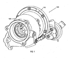
- FIG. 1 is a perspective view of a turbocharger in accordance with an embodiment of the invention
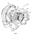
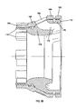
- FIG. 2 is a perspective view of the turbocharger of FIG. 1 , partially cut away to show details of the turbine assembly;
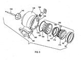
- FIG. 3 is an exploded view of the turbine assembly in accordance with an embodiment of the invention.
- FIG. 4A is a magnified portion of FIG. 2 , showing the turbine assembly in a closed position of the variable nozzle assembly;
- FIG. 4B is similar to FIG. 4A , showing the variable nozzle assembly in an open (bypass) position;
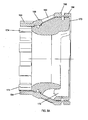
- FIG. 5A is a cross-sectional view of the variable nozzle assembly in the closed position
- FIG. 5B is similar to FIG. 5A , with the variable nozzle assembly in the open (bypass) position;
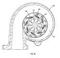
- FIG. 6 is a transverse cross-sectional view on a plane perpendicular to the rotational axis of the turbocharger, through the bypass openings and bypass channels of the variable nozzle assembly;
- FIG. 7A is a transverse cross-sectional view of the turbocharger, through the vanes of the variable nozzle assembly in the closed position;
- FIG. 7B is similar to FIG. 7A , but in the open (bypass) position;
- FIG. 8 is an exploded view of the variable nozzle assembly
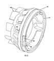
- FIG. 9 is a perspective view of the variable nozzle assembly.
- FIGS. 1-9 depict a turbocharger 100 and/or components thereof, in accordance with one embodiment of the present invention.
- the turbocharger includes a compressor housed by a compressor housing 110, a center housing 120 connected to the compressor housing for containing bearings for the rotating shaft of the turbocharger, and a turbine housed by a turbine housing 130.
- the present invention mainly concerns the turbine portion of the turbocharger, and thus details of the compressor portion and center housing components are not included herein for sake of brevity.
- the turbine housing 130 contains a turbine wheel 140 that is affixed to one end of a shaft 142, the other end of which is affixed to a compressor wheel (not shown) disposed in the compressor housing.
- the turbine wheel is located in an axial bore 132 defined by the turbine housing 130.
- the turbine housing defines a generally annular chamber 134 that surrounds the turbine wheel 140.
- a nozzle passage 136 is defined at a radially inner side of the chamber 134 through which exhaust gas in the chamber flows radially inwardly to the turbine wheel 140. The exhaust gas passes between the blades of the turbine wheel and is turned to flow axially along the bore 132 and exit the turbine housing.
- the turbocharger 100 includes a variable nozzle 150 of variable geometry for regulating the flow of exhaust gas through the nozzle.
- the variable nozzle is now described with reference primarily to FIGS. 4-9 .
- the variable nozzle comprises a stator 160 that is fixed in a rotational sense with respect to the turbine housing 130.
- the stator includes a tubular portion that extends circumferentially about the longitudinal axis of the turbocharger and defines a plurality of circumferentially spaced bypass openings 162 that are exposed to exhaust gas within the chamber 134.
- the stator also defines a plurality of circumferentially spaced fixed vanes 164 joined to the tubular portion and extending axially therefrom, into the nozzle passage 136.
- the tubular portion of the stator 160 includes a generally cylindrical portion 166 joined to a generally conical portion 168.
- the generally cylindrical portion 166 fits into portion of the bore 132 of the turbine housing and a sealing ring 167 is disposed in a groove defined in a radially outer surface of the generally cylindrical portion 166 for sealing against a radially inner surface of the turbine housing.
- the generally conical portion 168 extends from the generally cylindrical portion in an axially forward (i.e., toward the compressor section of the turbocharger) and radially inward direction.
- the bypass openings 162 are defined in the generally conical portion 168 of the stator 160.
- the variable nozzle further comprises a rotor 170 that is rotational with respect to the turbine housing 130 about the longitudinal axis of the turbocharger.
- the rotor includes a tubular portion that extends circumferentially about the longitudinal axis and defines a plurality of circumferentially spaced bypass channels 172 that are closed by the stator 160 when the rotor is in a closed position ( FIGS. 4A and 5A ) and that are respectively aligned with the bypass openings 162 in the stator when the rotor is in an open position ( FIGS. 4B and 5B ).
- the rotor also defines a plurality of circumferentially spaced movable vanes 174 joined to the tubular portion and extending axially therefrom, into the nozzle passage 136.
- the tubular portion of the rotor 170 includes a generally cylindrical portion 176 joined to a generally conical portion 178.
- the generally cylindrical portion 176 fits into the generally cylindrical portion 166 of the stator 160 and a sealing ring 177 is disposed in a groove defined in a radially outer surface of the generally cylindrical portion 176 for sealing against a radially inner surface of the stator 160.
- the generally conical portion 178 extends from the generally cylindrical portion 176 in an axially forward (i.e., toward the compressor section of the turbocharger) and radially inward direction.
- Each of the movable vanes 174 of the rotor 170 overlaps in a circumferential direction with a respective one of the fixed vanes 164 of the stator 160 to form a composite vane having a leading-edge portion defined by the fixed vane 164 and a trailing-edge portion defined by the movable vane 174.
- the term "movable vane” is not meant to denote that the vane is movable with respect to the rest of the rotor, but rather that the vane moves relative to the fixed vane when the rotor is rotated about the longitudinal axis, as further described below.
- the plurality of circumferentially spaced bypass channels 172 are defined in the generally conical portion 178 of the rotor 170.
- Each bypass channel 172 has an inlet defined at a radially outer side of the rotor, and an outlet that is in fluid communication with the turbine housing bore 132 at a position spaced downstream from the nozzle passage 136 with respect to flow of exhaust gas through the bore 132.
- the outlets of the bypass channels 172 are defined in an end surface of the rotor that extends between radially outer and inner surfaces of the rotor at its downstream end (i.e., the right-hand end in FIG. 5 ).
- the bypass channels are configured to discharge exhaust gas from the outlets of the bypass channels into the bore in the turbine housing in a generally axial direction.
- the rotor 170 is rotatable between a closed position in which the inlets to the bypass channels 172 are closed by the stator 160 (see FIGS. 4A and 5A ), and an open position in which the inlets to the bypass channels are aligned with the bypass openings 162 in the stator such that exhaust gas flows from the turbine housing chamber 134 through each bypass opening 162 and through the respective bypass channel 172 into the bore 132, bypassing the turbine wheel 140 (see FIGS. 4B and 5B ).
- an upstream portion of each bypass opening 162 extends in a direction having a circumferential component, for accommodating an expected degree of swirl existing in the turbine housing chamber 134.
- stator 160 is inserted into the turbine housing bore 132 from a downstream end thereof, and the rotor 170 is inserted into the stator in that same direction.
- a retaining ring 50 and snap ring 60 are then inserted behind the stator and rotor to retain these parts in place.
- the movable vanes 174 have a maximum degree of overlap (in the circumferential direction) with the fixed vanes 164 in the open position of the rotor 170 (see FIG. 7B ), and have a minimum degree of overlap with the fixed vanes in the closed position of the rotor 170 (see FIG. 7A ).
- the variable nozzle can include a stop for limiting rotation of the rotor 170 between predetermined closed and open positions.
- the stop is illustrated in FIGS. 8 and 9 .
- the stop comprises a projection 180 from the rotor, and a slot or opening 182 defined in the stator 160, the projection 180 abutting one end of the opening 182 to define the open position of the rotor and abutting an opposite end of the opening to define the closed position of the rotor.
- the stator could have a projection and the rotor could have an opening receiving the projection, or one of the rotor and stator could have a projection and the other could have a pair of spaced surfaces between which the projection is received.
- the stator 160 can include an integral locating projection that engages a receptacle defined in the turbine housing 130 so as to place the stator in a predetermined rotational orientation with respect to the turbine housing.
- the turbocharger 100 in accordance with the present invention includes an actuator linkage coupled with the rotor 170 for imparting rotational movement to the rotor.
- the actuator linkage can include a rotary member 190 ( FIG. 3 ) that extends generally radially inwardly through an aperture 138 in a wall of the turbine housing and is rotational about a generally radial axis.
- An outer end of the rotary member 190 that extends out from the turbine housing is coupled with a suitable actuator (not shown) for imparting the rotational movement to the rotary member and hence to the rotor 170.
- the linkage also includes an arm 192 that has one end attached to the inner end of the rotary member 190 and an opposite end engaged with the rotor 170, such that rotation of the rotary member 190 about the generally radial axis causes the arm 192 to pivot and impart rotational movement to the rotor (compare FIGS. 4A and 4B ).
- the rotary member 190 extends through a tubular bushing 194 installed in the aperture 138 in the turbine housing wall, which bushing serves as a bearing for rotation of the rotary member.
- the generally annular chamber that receives exhaust gas from the engine is defined substantially entirely by the turbine housing, and in particular, the turbine housing typically includes a wall at a radially inner side of the chamber that basically funnels the exhaust gas to the nozzle passage.
- the stator 160 has a radially outer surface that defines part of the generally annular chamber 134, the turbine housing 130 defining the remainder of the generally annular chamber. This is best seen in FIGS. 4A and 4B .
- the stator 160 in essence replaces the conventional turbine housing wall at the radially inner side of the chamber 134 that funnels the exhaust gas toward the nozzle passage.
- one of the walls defining the nozzle passage 136 is constituted entirely by the stator 160 and the rotor 170, and in particular by upstream end surfaces of the tubular portions of the stator and rotor.
- the opposite wall of the nozzle passage is defined at least in part by the turbine housing.
- exhaust gas flow into the turbine wheel 140 is regulated by adjusting the rotational position of the rotor 170 so as to vary the position of the movable vanes 174 relative to the fixed vanes 164.
- the rotor is positioned in the fully closed position ( FIGS. 4A , 5A , and 7A ) so that there is minimum overlap between the movable and fixed vanes, thereby reducing the flow passages between the vanes to a minimum size.
- the rotor is positioned in the fully open position ( FIGS.
Description
- The present disclosure relates to exhaust gas-driven turbochargers having variable turbine nozzles, and relates in particular to variable nozzles having the capability of bypassing some of the exhaust gas around the turbine wheel.
- Regulation of the exhaust gas flow through the turbine of an exhaust gas-driven turbocharger provides known operational advantages in terms of improved ability to control the amount of boost delivered by the turbocharger to the associated internal combustion engine. The regulation of exhaust gas flow is accomplished by incorporating variable geometry into the nozzle that leads into the turbine wheel. By varying the size of the nozzle flow area, the flow into the turbine wheel can be regulated, thereby regulating the overall boost provided by the turbocharger's compressor.
- Variable-geometry nozzles for turbochargers generally fall into two main categories: variable-vane nozzles, and sliding-piston nozzles. Vanes are often included in the turbine nozzle for directing the exhaust gas into the turbine in an advantageous direction. Typically a row of circumferentially spaced vanes extend axially across the nozzle. Exhaust gas from a generally annular chamber surrounding the turbine wheel flows generally radially inwardly through passages between the vanes, and the vanes turn the flow to direct the flow in a desired direction into the turbine wheel. In most variable-vane nozzles, the vanes are rotatable about their axes to vary the angle at which the vanes are set, thereby varying the flow area of the passages between the vanes.
- In the sliding-piston type of nozzle, the nozzle may also include vanes, but the vanes are fixed in position. Variation of the nozzle flow area is accomplished by an axially sliding piston that slides in a bore in the turbine housing. The piston is tubular and is located just radially inwardly of the nozzle. Axial movement of the piston is effective to vary the axial extent of the nozzle leading into the turbine wheel, thus varying the "throat area" at the turbine wheel inlet. When vanes are included in the nozzle, the piston can slide adjacent to radially inner (i.e., trailing) edges of the vanes; alternatively, the piston and vanes can overlap in the radial direction and the piston can include slots for receiving at least a portion of the vanes as the piston is slid axially to adjust the nozzle.
- There are times during the operation of a turbocharger when it is desired to pass as much flow through the turbine as possible. For example, it may be desirable to minimize the backpressure felt by the engine during certain operating conditions, and this is accomplished by reducing the flow restriction downstream of the engine as much as possible. In a sliding piston-type variable turbine nozzle, the downstream flow restriction is reduced by fully opening the piston to maximize the throat area at the turbine wheel inlet. However, in some cases, even fully opening the piston may not allow as much flow to pass as may be desired. Accordingly, some piston-type variable nozzles are configured to have a bypass passage that is opened when the piston is slid to a fully open position. The bypass passage extends between the generally annular chamber of the turbine housing and the bore in the turbine housing, such that exhaust gas flows from the chamber to the bore, bypassing the turbine wheel. Some turbines with variable-vane nozzles similarly include a bypass valve for bypassing the turbine wheel.
- Both the variable-vane and sliding piston types of variable nozzles have advantages and disadvantages. For example, variable-vane nozzles having rotatable vanes generally have good aerodynamic performance, but are mechanically complex because of the substantial number of moving parts. Sliding piston-type variable nozzles are mechanically much simpler, having far fewer moving parts, but generally are not as good aerodynamically as variable-vane nozzles.
- There is a third category of variable nozzle, represented for example by international patent application publication
WO 2004/074643 to Lombard et al. , in which the variable nozzle includes vanes each of which is made up of a fixed leading-edge portion (a fixed vane) and a movable trailing-edge portion (a movable vane). The movable vanes are supported on a rotor that is rotated about its axis to vary the positions of the movable vanes relative to the fixed vanes. This design offers mechanical simplicity combined with some of the advantages of vane-type nozzles. - The present disclosure concerns an improvement to the type of variable nozzle described in the aforementioned WO '643 publication. In particular, the present disclosure relates to a variable nozzle arrangement having an integrated bypass that requires no additional parts beyond those already needed for varying the nozzle flow area.
- In accordance with one embodiment described herein, a turbine assembly for an exhaust gas-driven turbocharger having a variable nozzle comprises:
- a turbine housing defining a generally annular chamber extending circumferentially about a longitudinal axis of the turbine housing, the turbine housing defining a bore extending along the longitudinal axis;
- a turbine wheel disposed in the turbine housing;
- a nozzle passage leading from the chamber radially inwardly into the turbine wheel, the nozzle passage being defined between two walls spaced apart in a longitudinal direction; and
- a variable nozzle assembly comprising (1) a stator that is fixed in a rotational sense with respect to the turbine housing and that defines a plurality of circumferentially spaced fixed vanes extending into the nozzle passage, (2) a rotor that is rotational with respect to the turbine housing about the longitudinal axis, the stator defines a bypass opening that is exposed to exhaust gas within the chamber, the bypass opening extending from a side of the stator exposed to the exhaust gas within the chamber through to an opposite side of the stator, and the rotor defines a bypass channel having an inlet on a site of the rotor adjacent the stator and an outlet on an opposite side of the rotor, the outlet being in fluid communication with the bore at a position spaced downstream from the nozzle passage with respect to flow of exhaust gas through the bore, and in that the rotor is rotatable between a closed position in which the inlet is closed by the stator and an open position in which the inlet is aligned with the bypass opening in the stator such that exhaust gas flows from the chamber through the bypass opening and through the bypass channel into the bore, bypassing the turbine wheel.
- In one embodiment, the stator includes a tubular portion that extends circumferentially about the longitudinal axis and defines a plurality of circumferentially spaced bypass openings, and the rotor includes a tubular portion that extends circumferentially about the longitudinal axis and defines a plurality of circumferentially spaced bypass channels that are closed by the stator when the rotor is in the closed position and that are respectively aligned with the bypass openings when the rotor is in the open position.
- The rotor advantageously defines a plurality of circumferentially spaced movable vanes each of which overlaps in a circumferential direction with a respective one of the fixed vanes to form a composite vane having a leading-edge portion defined by the fixed vane and a trailing-edge portion defined by the movable vane. Rotation of the rotor about the longitudinal axis is effective to vary the degree of overlap between the fixed and movable vanes, thereby varying the flow area of the nozzle. The movable vanes have a maximum degree of overlap with the fixed vanes (and hence flow area is a maximum) in the open position of the rotor, and have a minimum degree of overlap with the fixed vanes (and hence flow area is a minimum) in the closed position of the rotor.
- In one embodiment, the turbine assembly further comprises a stop for limiting rotation of the rotor between predetermined closed and open positions. The stop can comprise a projection from one of the rotor and stator that is disposed in an opening defined in the other of the rotor and stator, the projection abutting one end of the opening to define the open position of the rotor and abutting an opposite end of the opening to define the closed position of the rotor.
- It is also possible for the stator to include an integral locating projection that engages a receptacle defined in the turbine housing so as to place the stator in a predetermined rotational orientation with respect to the turbine housing.
- The turbine assembly can further comprise an actuator linkage coupled with the rotor for imparting rotational movement to the rotor. In one embodiment, the actuator linkage includes a rotary member that extends generally radially inwardly through a wall of the turbine housing and is rotational about a generally radial axis, and an arm that has one end attached to the rotary member and an opposite end engaged with the rotor, such that rotation of the rotary member about the generally radial axis causes the arm to pivot and impart rotational movement to the rotor.
- In accordance with one embodiment described herein, the tubular portion of the rotor has a radially outer surface and a radially inner surface, and the tubular portion of the stator has a radially inner surface that contacts the radially outer surface of the tubular portion of the rotor and forms a bearing surface for the rotor. The tubular portion of the stator can include a generally conical portion at an upstream end of the stator and a generally cylindrical portion at a downstream end of the stator, and the tubular portion of the rotor correspondingly can include a generally conical portion at an upstream end of the rotor and a generally cylindrical portion at a downstream end of the rotor. The bypass openings can be defined in the conical portion of the stator and the inlets of the bypass channels can be defined in the conical portion of the rotor.
- In one embodiment, an upstream portion of each bypass channel adjacent the inlet thereof extends in a direction having a circumferential component.
- The outlets of the bypass channels can be defined in an end surface of the rotor that extends between the radially outer and inner surfaces at the downstream end of the rotor. The bypass channels can be configured to discharge exhaust gas from the outlets of the bypass channels into the bore in the turbine housing in a generally axial direction.
- In one embodiment, the stator has a radially outer surface that defines part of the generally annular chamber, the turbine housing defining the remainder of the generally annular chamber. Additionally, one of the walls defining the nozzle passage is constituted entirely by the stator and the rotor.
- The turbine assembly in accordance with the present disclosure offers a number of advantages, including an ability to regulate turbine flow using a single moving part (the rotor), an integrated bypass functionality that does not require any additional parts, and mechanical simplicity.
- Having thus described the disclosure in general terms, reference will now be made to the accompanying drawings, which are not necessarily drawn to scale, and wherein:
-
FIG. 1 is a perspective view of a turbocharger in accordance with an embodiment of the invention; -
FIG. 2 is a perspective view of the turbocharger ofFIG. 1 , partially cut away to show details of the turbine assembly; -
FIG. 3 is an exploded view of the turbine assembly in accordance with an embodiment of the invention; -
FIG. 4A is a magnified portion ofFIG. 2 , showing the turbine assembly in a closed position of the variable nozzle assembly; -
FIG. 4B is similar toFIG. 4A , showing the variable nozzle assembly in an open (bypass) position; -
FIG. 5A is a cross-sectional view of the variable nozzle assembly in the closed position; -
FIG. 5B is similar toFIG. 5A , with the variable nozzle assembly in the open (bypass) position; -
FIG. 6 is a transverse cross-sectional view on a plane perpendicular to the rotational axis of the turbocharger, through the bypass openings and bypass channels of the variable nozzle assembly; -
FIG. 7A is a transverse cross-sectional view of the turbocharger, through the vanes of the variable nozzle assembly in the closed position; -
FIG. 7B is similar toFIG. 7A , but in the open (bypass) position; -
FIG. 8 is an exploded view of the variable nozzle assembly; and -
FIG. 9 is a perspective view of the variable nozzle assembly. - The present invention now will be described more fully hereinafter with reference to the accompanying drawings in which some but not all embodiments of the inventions are shown. Indeed, these inventions may be embodied in many different forms and should not be construed as limited to the embodiments set forth herein; rather, these embodiments are provided so that this disclosure will satisfy applicable legal requirements. Like numbers refer to like elements throughout.
-
FIGS. 1-9 depict aturbocharger 100 and/or components thereof, in accordance with one embodiment of the present invention. The turbocharger includes a compressor housed by acompressor housing 110, acenter housing 120 connected to the compressor housing for containing bearings for the rotating shaft of the turbocharger, and a turbine housed by aturbine housing 130. The present invention mainly concerns the turbine portion of the turbocharger, and thus details of the compressor portion and center housing components are not included herein for sake of brevity. - With reference primarily to
FIGS. 2-4 , theturbine housing 130 contains aturbine wheel 140 that is affixed to one end of ashaft 142, the other end of which is affixed to a compressor wheel (not shown) disposed in the compressor housing. The turbine wheel is located in anaxial bore 132 defined by theturbine housing 130. The turbine housing defines a generallyannular chamber 134 that surrounds theturbine wheel 140. Anozzle passage 136 is defined at a radially inner side of thechamber 134 through which exhaust gas in the chamber flows radially inwardly to theturbine wheel 140. The exhaust gas passes between the blades of the turbine wheel and is turned to flow axially along thebore 132 and exit the turbine housing. - The
turbocharger 100 includes avariable nozzle 150 of variable geometry for regulating the flow of exhaust gas through the nozzle. The variable nozzle is now described with reference primarily toFIGS. 4-9 . The variable nozzle comprises astator 160 that is fixed in a rotational sense with respect to theturbine housing 130. The stator includes a tubular portion that extends circumferentially about the longitudinal axis of the turbocharger and defines a plurality of circumferentially spacedbypass openings 162 that are exposed to exhaust gas within thechamber 134. The stator also defines a plurality of circumferentially spaced fixedvanes 164 joined to the tubular portion and extending axially therefrom, into thenozzle passage 136. The tubular portion of thestator 160 includes a generallycylindrical portion 166 joined to a generallyconical portion 168. The generallycylindrical portion 166 fits into portion of thebore 132 of the turbine housing and asealing ring 167 is disposed in a groove defined in a radially outer surface of the generallycylindrical portion 166 for sealing against a radially inner surface of the turbine housing. The generallyconical portion 168 extends from the generally cylindrical portion in an axially forward (i.e., toward the compressor section of the turbocharger) and radially inward direction. Thebypass openings 162 are defined in the generallyconical portion 168 of thestator 160. - The variable nozzle further comprises a
rotor 170 that is rotational with respect to theturbine housing 130 about the longitudinal axis of the turbocharger. The rotor includes a tubular portion that extends circumferentially about the longitudinal axis and defines a plurality of circumferentially spacedbypass channels 172 that are closed by thestator 160 when the rotor is in a closed position (FIGS. 4A and5A ) and that are respectively aligned with thebypass openings 162 in the stator when the rotor is in an open position (FIGS. 4B and5B ). The rotor also defines a plurality of circumferentially spacedmovable vanes 174 joined to the tubular portion and extending axially therefrom, into thenozzle passage 136. The tubular portion of therotor 170 includes a generallycylindrical portion 176 joined to a generallyconical portion 178. The generallycylindrical portion 176 fits into the generallycylindrical portion 166 of thestator 160 and asealing ring 177 is disposed in a groove defined in a radially outer surface of the generallycylindrical portion 176 for sealing against a radially inner surface of thestator 160. Additionally, there is asecond sealing ring 179 disposed in a groove in the radially outer surface of the generallyconical portion 178 for sealing against a radially inner surface of the stator. The generallyconical portion 178 extends from the generallycylindrical portion 176 in an axially forward (i.e., toward the compressor section of the turbocharger) and radially inward direction. Each of themovable vanes 174 of therotor 170 overlaps in a circumferential direction with a respective one of the fixedvanes 164 of thestator 160 to form a composite vane having a leading-edge portion defined by the fixedvane 164 and a trailing-edge portion defined by themovable vane 174. The term "movable vane" is not meant to denote that the vane is movable with respect to the rest of the rotor, but rather that the vane moves relative to the fixed vane when the rotor is rotated about the longitudinal axis, as further described below. - The plurality of circumferentially spaced
bypass channels 172 are defined in the generallyconical portion 178 of therotor 170. Eachbypass channel 172 has an inlet defined at a radially outer side of the rotor, and an outlet that is in fluid communication with the turbine housing bore 132 at a position spaced downstream from thenozzle passage 136 with respect to flow of exhaust gas through thebore 132. In the illustrated embodiment, the outlets of thebypass channels 172 are defined in an end surface of the rotor that extends between radially outer and inner surfaces of the rotor at its downstream end (i.e., the right-hand end inFIG. 5 ). Furthermore, the bypass channels are configured to discharge exhaust gas from the outlets of the bypass channels into the bore in the turbine housing in a generally axial direction. - As noted, the
rotor 170 is rotatable between a closed position in which the inlets to thebypass channels 172 are closed by the stator 160 (seeFIGS. 4A and5A ), and an open position in which the inlets to the bypass channels are aligned with thebypass openings 162 in the stator such that exhaust gas flows from theturbine housing chamber 134 through eachbypass opening 162 and through therespective bypass channel 172 into thebore 132, bypassing the turbine wheel 140 (seeFIGS. 4B and5B ). In one embodiment, as best seen inFIG. 6 , an upstream portion of eachbypass opening 162 extends in a direction having a circumferential component, for accommodating an expected degree of swirl existing in theturbine housing chamber 134. - To assemble the variable nozzle, the
stator 160 is inserted into the turbine housing bore 132 from a downstream end thereof, and therotor 170 is inserted into the stator in that same direction. A retainingring 50 andsnap ring 60 are then inserted behind the stator and rotor to retain these parts in place. - The
movable vanes 174 have a maximum degree of overlap (in the circumferential direction) with the fixedvanes 164 in the open position of the rotor 170 (seeFIG. 7B ), and have a minimum degree of overlap with the fixed vanes in the closed position of the rotor 170 (seeFIG. 7A ). - In accordance with one embodiment of the invention, the variable nozzle can include a stop for limiting rotation of the
rotor 170 between predetermined closed and open positions. The stop is illustrated inFIGS. 8 and9 . The stop comprises aprojection 180 from the rotor, and a slot or opening 182 defined in thestator 160, theprojection 180 abutting one end of theopening 182 to define the open position of the rotor and abutting an opposite end of the opening to define the closed position of the rotor. Alternatively, the stator could have a projection and the rotor could have an opening receiving the projection, or one of the rotor and stator could have a projection and the other could have a pair of spaced surfaces between which the projection is received. - The
stator 160 can include an integral locating projection that engages a receptacle defined in theturbine housing 130 so as to place the stator in a predetermined rotational orientation with respect to the turbine housing. - The
turbocharger 100 in accordance with the present invention includes an actuator linkage coupled with therotor 170 for imparting rotational movement to the rotor. The actuator linkage can include a rotary member 190 (FIG. 3 ) that extends generally radially inwardly through anaperture 138 in a wall of the turbine housing and is rotational about a generally radial axis. An outer end of therotary member 190 that extends out from the turbine housing is coupled with a suitable actuator (not shown) for imparting the rotational movement to the rotary member and hence to therotor 170. The linkage also includes anarm 192 that has one end attached to the inner end of therotary member 190 and an opposite end engaged with therotor 170, such that rotation of therotary member 190 about the generally radial axis causes thearm 192 to pivot and impart rotational movement to the rotor (compareFIGS. 4A and4B ). As shown inFIG. 3 , therotary member 190 extends through atubular bushing 194 installed in theaperture 138 in the turbine housing wall, which bushing serves as a bearing for rotation of the rotary member. - Another aspect of the invention concerns the configuration of the
turbine housing 130. In a typical turbocharger, the generally annular chamber that receives exhaust gas from the engine is defined substantially entirely by the turbine housing, and in particular, the turbine housing typically includes a wall at a radially inner side of the chamber that basically funnels the exhaust gas to the nozzle passage. However, in accordance with the invention in one embodiment, thestator 160 has a radially outer surface that defines part of the generallyannular chamber 134, theturbine housing 130 defining the remainder of the generally annular chamber. This is best seen inFIGS. 4A and4B . In particular, thestator 160 in essence replaces the conventional turbine housing wall at the radially inner side of thechamber 134 that funnels the exhaust gas toward the nozzle passage. - Additionally, in one embodiment of the invention, one of the walls defining the
nozzle passage 136 is constituted entirely by thestator 160 and therotor 170, and in particular by upstream end surfaces of the tubular portions of the stator and rotor. The opposite wall of the nozzle passage is defined at least in part by the turbine housing. - In operation of the
turbocharger 100 in accordance with the invention, exhaust gas flow into theturbine wheel 140 is regulated by adjusting the rotational position of therotor 170 so as to vary the position of themovable vanes 174 relative to the fixedvanes 164. For example, when minimum flow through the turbine is desired at a particular engine operating condition, the rotor is positioned in the fully closed position (FIGS. 4A ,5A , and7A ) so that there is minimum overlap between the movable and fixed vanes, thereby reducing the flow passages between the vanes to a minimum size. When maximum flow through the turbine is desired, the rotor is positioned in the fully open position (FIGS. 4B ,5B , and7B ), which not only maximizes the flow passages between the vanes, but also opens thebypass channels 172 in therotor 170 so that a proportion of the exhaust gas in thechamber 134 bypasses theturbine wheel 140 and flows directly into thebore 132 in the turbine housing at a location downstream of thenozzle passage 136. - Many modifications and other embodiments of the inventions set forth herein will come to mind to one skilled in the art to which these inventions pertain having the benefit of the teachings presented in the foregoing descriptions and the associated drawings. Therefore, it is to be understood that the inventions are not to be limited to the specific embodiments disclosed and that modifications and other embodiments are intended to be included within the scope of the appended claims. Although specific terms are employed herein, they are used in a generic and descriptive sense only and not for purposes of limitation.
Claims (16)
- A turbine assembly for an exhaust gas-driven turbocharger (100) having a variable nozzle, comprising:a turbine housing defining at least part of a generally annular chamber (134) extending circumferentially about a longitudinal axis of the turbine housing (130), the turbine housing defining a bore extending along the longitudinal axis;a turbine wheel (140) disposed in the turbine housing;a nozzle passage (136) leading from the chamber radially inwardly into the turbine wheel, the nozzle passage being defined between two walls spaced apart in a longitudinal direction; anda variable nozzle assembly (150) comprising:a stator (160) that is fixed in a rotational sense with respect to the turbine housing and that defines a plurality of circumferentially spaced fixed vanes (164) extending into the nozzle passage; anda rotor (170) that is rotational with respect to the turbine housing about the longitudinal axis, characterized in that:the stator (160) defines a bypass opening that is exposed to exhaust gas within the chamber, the bypass opening (162) extending from a side of the stator (160) exposed to the exhaust gas within the chamber through to an opposite side of the stator, and the rotor defines a bypass channel having an inlet on a side of the rotor (170) adjacent the stator and an outlet on an opposite side of the rotor (170), the outlet being in fluid communication with the bore at a position spaced downstream from the nozzle passage with respect to flow of exhaust gas through the bore, and in that the rotor (170) is rotatable between a closed position in which the inlet is closed by the stator (160) and an open position in which the inlet is aligned with the bypass opening in the stator such that exhaust gas flows from the chamber through the bypass opening and through the bypass channel into the bore, bypassing the turbine wheel.
- The turbine assembly of claim 1, wherein the stator includes a tubular portion that extends circumferentially about the longitudinal axis and defines a plurality of circumferentially spaced bypass openings, and the rotor includes a tubular portion that extends circumferentially about the longitudinal axis and defines a plurality of circumferentially spaced bypass channels (172) that are closed by the stator when the rotor is in the closed position and that are respectively aligned with the bypass openings (162) when the rotor is in the open position.
- The turbine assembly of claim 2, wherein the rotor defines a plurality of circumferentially spaced movable vanes (174) each of which overlaps in a circumferential direction with a respective one of the fixed vanes (164) to form a composite vane having a leading-edge portion defined by the fixed vane and a trailing-edge portion defined by the movable vane.
- The turbine assembly of claim 3, wherein the movable vanes (174) have a maximum degree of overlap with the fixed vanes (164) in the open position of the rotor, and have a minimum degree of overlap with the fixed vanes (164) in the closed position of the rotor (170).
- The turbine assembly of claim 3, further comprising a stop (180, 182) for limiting rotation of the rotor (170) between predetermined closed and open positions.
- The turbine assembly of claim 5, wherein the stop comprises a projection (180) from the rotor (170) that is disposed in an opening (182) defined in the stator (160) or a projection from the stator (160) that is disposed in an opening defined in the rotor (170), the projection abutting one end of the opening to define the open position of the rotor (170) and abutting an opposite end of the opening to define the closed position of the rotor (170).
- The turbine assembly of claim 1, wherein the stator includes an integral locating projection that engages a receptacle defined in the turbine housing so as to place the stator (160) in a predetermined rotational orientation with respect to the turbine housing.
- The turbine assembly of claim 1, further comprising an actuator linkage coupled with the rotor (170) for imparting rotational movement to the rotor.
- The turbine assembly of claim 8, wherein the actuator linkage includes a rotary member (190) that extends generally radially inwardly through a wall of the turbine housing and is rotational about a generally radial axis, and an arm that has one end attached to the rotary member (190) and an opposite end engaged with the rotor, such that rotation of the rotary member about the generally radial axis causes the arm to pivot and impart rotational movement to the rotor (170).
- The turbine assembly of claim 2, wherein the tubular portion of the rotor has a radially outer surface and a radially inner surface, and the tubular portion of the stator (160) has a radially inner surface that contacts the radially outer surface of the tubular portion of the rotor (170) and forms a bearing surface for the rotor (170).
- The turbine assembly of claim 10, wherein the tubular portion of the stator (160) includes a generally conical portion at an upstream end of the stator (160) and a generally cylindrical portion (166) at a downstream end of the stator, and the tubular portion of the rotor (170) correspondingly includes a generally conical portion (168) at an upstream end of the rotor and a generally cylindrical portion at a downstream end of the rotor, and wherein the bypass openings are defined in the conical portion (168) of the stator (160) and the inlets of the bypass channels are defined in the conical portion of the rotor (170).
- The turbine assembly of claim 10, wherein an upstream portion of each bypass opening extends in a direction having a circumferential component.
- The turbine assembly of claim 10, wherein the outlets of the bypass channels (172) are defined in an end surface of the rotor (170) that extends between the radially outer and inner surfaces at the downstream end of the rotor (170).
- The turbine assembly of claim 13, wherein the bypass channels (172) in the rotor (170) are configured to discharge exhaust gas from the outlets of the bypass channels into the bore in the turbine housing in a generally axial direction.
- The turbine assembly of claim 1, wherein the stator (160) has a radially outer surface that defines part of the generally annular chamber, the turbine housing defining the remainder of the generally annular chamber.
- The turbine assembly of claim 15, wherein one of the walls defining the nozzle passage is constituted entirely by the stator (160) and the rotor (170).
Applications Claiming Priority (1)
| Application Number | Priority Date | Filing Date | Title |
|---|---|---|---|
| US12/364,715 US8113770B2 (en) | 2009-02-03 | 2009-02-03 | Turbine assembly for an exhaust gas-driven turbocharger having a variable nozzle |
Publications (3)
| Publication Number | Publication Date |
|---|---|
| EP2213865A2 EP2213865A2 (en) | 2010-08-04 |
| EP2213865A3 EP2213865A3 (en) | 2014-01-22 |
| EP2213865B1 true EP2213865B1 (en) | 2014-12-17 |
Family
ID=42166464
Family Applications (1)
| Application Number | Title | Priority Date | Filing Date |
|---|---|---|---|
| EP10151602.9A Active EP2213865B1 (en) | 2009-02-03 | 2010-01-25 | Turbine assembly for an exhaust gas-driven turbocharger having a variable nozzle |
Country Status (3)
| Country | Link |
|---|---|
| US (1) | US8113770B2 (en) |
| EP (1) | EP2213865B1 (en) |
| CN (1) | CN102061948B (en) |
Families Citing this family (20)
| Publication number | Priority date | Publication date | Assignee | Title |
|---|---|---|---|---|
| US8814499B2 (en) * | 2010-04-19 | 2014-08-26 | Korea Fluid Machinery Co., Ltd. | Centrifugal compressor |
| US8573929B2 (en) * | 2010-04-30 | 2013-11-05 | Honeywell International Inc. | Turbocharger with turbine nozzle vanes and an annular rotary bypass valve |
| DE102010021928A1 (en) * | 2010-05-28 | 2011-12-01 | Daimler Ag | Turbine for an exhaust gas turbocharger |
| US8919119B2 (en) * | 2011-08-16 | 2014-12-30 | Ford Global Technologies, Llc | Sliding vane geometry turbines |
| DE102012202907B4 (en) | 2012-02-27 | 2018-09-20 | Continental Automotive Gmbh | Exhaust gas turbocharger with relatively rotatable Leitgitterringen |
| DE102012103411A1 (en) * | 2012-04-19 | 2013-10-24 | Ihi Charging Systems International Gmbh | Turbine for an exhaust gas turbocharger |
| DE102012016984B4 (en) | 2012-08-28 | 2022-12-08 | Mercedes-Benz Group AG | Turbine for an exhaust gas turbocharger and internal combustion engine with such a turbine |
| GB201308680D0 (en) * | 2013-05-14 | 2013-06-26 | Imp Innovations Ltd | A flow control device for a turbocharger |
| US10107296B2 (en) * | 2013-06-25 | 2018-10-23 | Ford Global Technologies, Llc | Turbocharger systems and method to prevent compressor choke |
| US9593690B2 (en) * | 2013-06-26 | 2017-03-14 | Honeywell International Inc. | Turbocharger with an annular rotary bypass valve |
| DE102013021567A1 (en) | 2013-12-19 | 2014-07-31 | Daimler Ag | Turbine for supercharger of internal combustion engine mounted in motor vehicle, has coil segments that are formed to vary asymmetry degree by quotient of exhaust gas flow parameters by adjusting adjustment device in switching position |
| US9845723B2 (en) * | 2014-11-24 | 2017-12-19 | Honeywell International Inc. | Adjustable-trim centrifugal compressor, and turbocharger having same |
| CN104500267B (en) * | 2014-12-26 | 2016-02-10 | 南京凌日星能源科技有限公司 | For regulating the fan-shaped throttling arrangement of turbine electricity generation system power |
| CN106090424A (en) * | 2016-04-21 | 2016-11-09 | 杜建波 | A kind of valve of recyclable fluid energy |
| US10527047B2 (en) * | 2017-01-25 | 2020-01-07 | Energy Labs, Inc. | Active stall prevention in centrifugal fans |
| DE102017216332A1 (en) * | 2017-09-14 | 2019-03-14 | Continental Automotive Gmbh | Compressor for a charging device of an internal combustion engine and charging device for an internal combustion engine |
| US20190153889A1 (en) * | 2017-11-22 | 2019-05-23 | Ford Global Technologies, Llc | Systems and methods for a variable geometry turbine nozzle actuation |
| US20190178255A1 (en) * | 2017-12-12 | 2019-06-13 | Honeywell International Inc. | Vapor cycle compressor with variable inlet/outlet geometry |
| KR102585747B1 (en) * | 2018-05-04 | 2023-10-11 | 현대자동차주식회사 | Vgt for vehicle |
| CN217107202U (en) * | 2020-09-23 | 2022-08-02 | 博格华纳公司 | Compressor assembly and turbocharger for vehicle |
Citations (1)
| Publication number | Priority date | Publication date | Assignee | Title |
|---|---|---|---|---|
| EP0433560A1 (en) * | 1989-12-18 | 1991-06-26 | Dr.Ing.h.c. F. Porsche Aktiengesellschaft | Exhaust gas turbocharger for an internal combustion engine |
Family Cites Families (18)
| Publication number | Priority date | Publication date | Assignee | Title |
|---|---|---|---|---|
| US2648195A (en) * | 1945-12-28 | 1953-08-11 | Rolls Royce | Centrifugal compressor for supercharging internal-combustion engines |
| SU715812A1 (en) | 1978-02-20 | 1980-02-15 | Предприятие П/Я А-1665 | Adjustable nozzle vane unit of centripetal turbine |
| JPH01227823A (en) * | 1988-03-08 | 1989-09-12 | Honda Motor Co Ltd | Variable nozzle structure of turbine |
| DE4238550A1 (en) * | 1992-11-14 | 1994-05-19 | Daimler Benz Ag | Exhaust gas turbocharger for an internal combustion engine |
| DE4330487C1 (en) * | 1993-09-09 | 1995-01-26 | Daimler Benz Ag | Exhaust gas turbocharger for an internal combustion engine |
| DE19651498C1 (en) * | 1996-12-11 | 1998-04-16 | Daimler Benz Ag | Exhaust turbocharger for IC engine |
| DE10028733A1 (en) * | 2000-06-09 | 2001-12-13 | Daimler Chrysler Ag | Exhaust turbine for turbocharger ha guide blades with flow intake edges and/or outflow edges at angle relative to jacket line, and cover rings to connected blade ends |
| US6564554B2 (en) * | 2001-08-07 | 2003-05-20 | Caterpillar Inc | Method and apparatus to control a turbocharger wastegate using exhaust pressure |
| GB0227473D0 (en) * | 2002-11-25 | 2002-12-31 | Leavesley Malcolm G | Variable turbocharger apparatus with bypass apertures |
| US7458764B2 (en) * | 2003-02-19 | 2008-12-02 | Honeywell International, Inc. | Nozzle device for a turbocharger and associated control method |
| US20080038110A1 (en) * | 2003-10-24 | 2008-02-14 | Honeywell International, Inc. | Sector-Divided Turbine Assembly With Axial Piston Variable-Geometry Mechanism |
| US6945048B2 (en) * | 2003-10-30 | 2005-09-20 | Deere & Company | Exhaust pressure restriction device with bypass passageway |
| WO2007058647A1 (en) | 2005-11-16 | 2007-05-24 | Honeywell International Inc. | Sliding piston cartridge and turbocharger incorporating same |
| US8197195B2 (en) * | 2005-11-16 | 2012-06-12 | Honeywell International Inc. | Turbocharger with stepped two-stage vane nozzle |
| US7249930B2 (en) * | 2005-11-29 | 2007-07-31 | Honeywell International, Inc. | Variable-nozzle turbocharger with integrated bypass |
| US7360362B2 (en) * | 2006-01-20 | 2008-04-22 | Honeywell International, Inc. | Two-stage turbocharger system with integrated exhaust manifold and bypass assembly |
| US7908860B2 (en) * | 2008-01-22 | 2011-03-22 | Ford Global Technologies, Llc | Split-series sequential turbocharged engine |
| US8997353B2 (en) * | 2008-03-08 | 2015-04-07 | Cummins Ip, Inc. | Apparatus, system, and method for shaping a valve orifice |
-
2009
- 2009-02-03 US US12/364,715 patent/US8113770B2/en active Active
-
2010
- 2010-01-25 EP EP10151602.9A patent/EP2213865B1/en active Active
- 2010-02-02 CN CN201010121036.7A patent/CN102061948B/en not_active Expired - Fee Related
Patent Citations (1)
| Publication number | Priority date | Publication date | Assignee | Title |
|---|---|---|---|---|
| EP0433560A1 (en) * | 1989-12-18 | 1991-06-26 | Dr.Ing.h.c. F. Porsche Aktiengesellschaft | Exhaust gas turbocharger for an internal combustion engine |
Also Published As
| Publication number | Publication date |
|---|---|
| CN102061948B (en) | 2014-12-24 |
| EP2213865A3 (en) | 2014-01-22 |
| US8113770B2 (en) | 2012-02-14 |
| CN102061948A (en) | 2011-05-18 |
| US20100196145A1 (en) | 2010-08-05 |
| EP2213865A2 (en) | 2010-08-04 |
Similar Documents
| Publication | Publication Date | Title |
|---|---|---|
| EP2213865B1 (en) | Turbine assembly for an exhaust gas-driven turbocharger having a variable nozzle | |
| EP1957757B1 (en) | Turbocharger having an axially sliding piston cartridge | |
| US8123470B2 (en) | Turbine assembly with semi-divided nozzle and half-collar piston | |
| EP2317080B1 (en) | Turbine assembly for a turbocharger, having twin volutes, and associated method | |
| EP1866534B1 (en) | Variable flow turbocharger | |
| EP3018355B1 (en) | Adjustable-trim centrifugal compressor, and turbocharger having same | |
| EP2022963B1 (en) | Variable-geometry turbocharger with asymmetric divided volute for engine exhaust gas pulse optimization | |
| EP1352157B1 (en) | Variable geometry turbocharger with improved vane actuation | |
| EP2564044B1 (en) | Turbocharger with turbine nozzle vanes and an annular rotary bypass valve | |
| US10900415B2 (en) | Turbocharger having a meridionally divided turbine housing and a variable turbine nozzle | |
| EP2818666B1 (en) | Turbocharger with turbine nozzle vanes and an annular rotary bypass valve | |
| US20080038110A1 (en) | Sector-Divided Turbine Assembly With Axial Piston Variable-Geometry Mechanism | |
| EP3103988B1 (en) | Turbocharger with variable-vane turbine nozzle having a bypass mechanism integrated with the vanes | |
| MXPA05000037A (en) | Variable geometry turbocharger having internal bypass exhaust gas flow. | |
| EP2028347B1 (en) | Turbocharger with sliding piston assembly | |
| EP3301277B1 (en) | Turbocharger with ported turbine shroud | |
| EP2035673B1 (en) | Variable stator blade mechanism for turbochargers | |
| US7249930B2 (en) | Variable-nozzle turbocharger with integrated bypass | |
| EP3708780B1 (en) | Turbocharger having variable-vane turbine nozzle including spacers that also serve as hard stops for the vanes | |
| JP4885949B2 (en) | Variable vane turbine |
Legal Events
| Date | Code | Title | Description |
|---|---|---|---|
| PUAI | Public reference made under article 153(3) epc to a published international application that has entered the european phase |
Free format text: ORIGINAL CODE: 0009012 |
|
| 17P | Request for examination filed |
Effective date: 20100125 |
|
| AK | Designated contracting states |
Kind code of ref document: A2 Designated state(s): AT BE BG CH CY CZ DE DK EE ES FI FR GB GR HR HU IE IS IT LI LT LU LV MC MK MT NL NO PL PT RO SE SI SK SM TR |
|
| PUAL | Search report despatched |
Free format text: ORIGINAL CODE: 0009013 |
|
| AK | Designated contracting states |
Kind code of ref document: A3 Designated state(s): AT BE BG CH CY CZ DE DK EE ES FI FR GB GR HR HU IE IS IT LI LT LU LV MC MK MT NL NO PL PT RO SE SI SK SM TR |
|
| RIC1 | Information provided on ipc code assigned before grant |
Ipc: F02C 6/12 20060101AFI20131216BHEP Ipc: F01D 17/14 20060101ALI20131216BHEP Ipc: F01D 17/18 20060101ALI20131216BHEP |
|
| 17Q | First examination report despatched |
Effective date: 20140120 |
|
| GRAP | Despatch of communication of intention to grant a patent |
Free format text: ORIGINAL CODE: EPIDOSNIGR1 |
|
| INTG | Intention to grant announced |
Effective date: 20140807 |
|
| GRAS | Grant fee paid |
Free format text: ORIGINAL CODE: EPIDOSNIGR3 |
|
| GRAA | (expected) grant |
Free format text: ORIGINAL CODE: 0009210 |
|
| AK | Designated contracting states |
Kind code of ref document: B1 Designated state(s): AT BE BG CH CY CZ DE DK EE ES FI FR GB GR HR HU IE IS IT LI LT LU LV MC MK MT NL NO PL PT RO SE SI SK SM TR |
|
| REG | Reference to a national code |
Ref country code: GB Ref legal event code: FG4D |
|
| REG | Reference to a national code |
Ref country code: CH Ref legal event code: EP |
|
| REG | Reference to a national code |
Ref country code: IE Ref legal event code: FG4D |
|
| REG | Reference to a national code |
Ref country code: AT Ref legal event code: REF Ref document number: 702116 Country of ref document: AT Kind code of ref document: T Effective date: 20150115 |
|
| REG | Reference to a national code |
Ref country code: DE Ref legal event code: R096 Ref document number: 602010020991 Country of ref document: DE Effective date: 20150205 |
|
| PG25 | Lapsed in a contracting state [announced via postgrant information from national office to epo] |
Ref country code: NO Free format text: LAPSE BECAUSE OF FAILURE TO SUBMIT A TRANSLATION OF THE DESCRIPTION OR TO PAY THE FEE WITHIN THE PRESCRIBED TIME-LIMIT Effective date: 20150317 Ref country code: FI Free format text: LAPSE BECAUSE OF FAILURE TO SUBMIT A TRANSLATION OF THE DESCRIPTION OR TO PAY THE FEE WITHIN THE PRESCRIBED TIME-LIMIT Effective date: 20141217 Ref country code: LT Free format text: LAPSE BECAUSE OF FAILURE TO SUBMIT A TRANSLATION OF THE DESCRIPTION OR TO PAY THE FEE WITHIN THE PRESCRIBED TIME-LIMIT Effective date: 20141217 |
|
| REG | Reference to a national code |
Ref country code: LT Ref legal event code: MG4D |
|
| PG25 | Lapsed in a contracting state [announced via postgrant information from national office to epo] |
Ref country code: HR Free format text: LAPSE BECAUSE OF FAILURE TO SUBMIT A TRANSLATION OF THE DESCRIPTION OR TO PAY THE FEE WITHIN THE PRESCRIBED TIME-LIMIT Effective date: 20141217 Ref country code: SE Free format text: LAPSE BECAUSE OF FAILURE TO SUBMIT A TRANSLATION OF THE DESCRIPTION OR TO PAY THE FEE WITHIN THE PRESCRIBED TIME-LIMIT Effective date: 20141217 Ref country code: LV Free format text: LAPSE BECAUSE OF FAILURE TO SUBMIT A TRANSLATION OF THE DESCRIPTION OR TO PAY THE FEE WITHIN THE PRESCRIBED TIME-LIMIT Effective date: 20141217 Ref country code: GR Free format text: LAPSE BECAUSE OF FAILURE TO SUBMIT A TRANSLATION OF THE DESCRIPTION OR TO PAY THE FEE WITHIN THE PRESCRIBED TIME-LIMIT Effective date: 20150318 |
|
| REG | Reference to a national code |
Ref country code: AT Ref legal event code: MK05 Ref document number: 702116 Country of ref document: AT Kind code of ref document: T Effective date: 20141217 |
|
| PG25 | Lapsed in a contracting state [announced via postgrant information from national office to epo] |
Ref country code: NL Free format text: LAPSE BECAUSE OF FAILURE TO SUBMIT A TRANSLATION OF THE DESCRIPTION OR TO PAY THE FEE WITHIN THE PRESCRIBED TIME-LIMIT Effective date: 20141217 |
|
| PG25 | Lapsed in a contracting state [announced via postgrant information from national office to epo] |
Ref country code: EE Free format text: LAPSE BECAUSE OF FAILURE TO SUBMIT A TRANSLATION OF THE DESCRIPTION OR TO PAY THE FEE WITHIN THE PRESCRIBED TIME-LIMIT Effective date: 20141217 Ref country code: ES Free format text: LAPSE BECAUSE OF FAILURE TO SUBMIT A TRANSLATION OF THE DESCRIPTION OR TO PAY THE FEE WITHIN THE PRESCRIBED TIME-LIMIT Effective date: 20141217 Ref country code: SK Free format text: LAPSE BECAUSE OF FAILURE TO SUBMIT A TRANSLATION OF THE DESCRIPTION OR TO PAY THE FEE WITHIN THE PRESCRIBED TIME-LIMIT Effective date: 20141217 Ref country code: CZ Free format text: LAPSE BECAUSE OF FAILURE TO SUBMIT A TRANSLATION OF THE DESCRIPTION OR TO PAY THE FEE WITHIN THE PRESCRIBED TIME-LIMIT Effective date: 20141217 Ref country code: RO Free format text: LAPSE BECAUSE OF FAILURE TO SUBMIT A TRANSLATION OF THE DESCRIPTION OR TO PAY THE FEE WITHIN THE PRESCRIBED TIME-LIMIT Effective date: 20141217 Ref country code: PT Free format text: LAPSE BECAUSE OF FAILURE TO SUBMIT A TRANSLATION OF THE DESCRIPTION OR TO PAY THE FEE WITHIN THE PRESCRIBED TIME-LIMIT Effective date: 20150417 |
|
| REG | Reference to a national code |
Ref country code: CH Ref legal event code: PL |
|
| PG25 | Lapsed in a contracting state [announced via postgrant information from national office to epo] |
Ref country code: IS Free format text: LAPSE BECAUSE OF FAILURE TO SUBMIT A TRANSLATION OF THE DESCRIPTION OR TO PAY THE FEE WITHIN THE PRESCRIBED TIME-LIMIT Effective date: 20150417 Ref country code: LU Free format text: LAPSE BECAUSE OF FAILURE TO SUBMIT A TRANSLATION OF THE DESCRIPTION OR TO PAY THE FEE WITHIN THE PRESCRIBED TIME-LIMIT Effective date: 20150125 Ref country code: AT Free format text: LAPSE BECAUSE OF FAILURE TO SUBMIT A TRANSLATION OF THE DESCRIPTION OR TO PAY THE FEE WITHIN THE PRESCRIBED TIME-LIMIT Effective date: 20141217 Ref country code: PL Free format text: LAPSE BECAUSE OF FAILURE TO SUBMIT A TRANSLATION OF THE DESCRIPTION OR TO PAY THE FEE WITHIN THE PRESCRIBED TIME-LIMIT Effective date: 20141217 |
|
| REG | Reference to a national code |
Ref country code: DE Ref legal event code: R097 Ref document number: 602010020991 Country of ref document: DE |
|
| PG25 | Lapsed in a contracting state [announced via postgrant information from national office to epo] |
Ref country code: MC Free format text: LAPSE BECAUSE OF FAILURE TO SUBMIT A TRANSLATION OF THE DESCRIPTION OR TO PAY THE FEE WITHIN THE PRESCRIBED TIME-LIMIT Effective date: 20141217 |
|
| PLBE | No opposition filed within time limit |
Free format text: ORIGINAL CODE: 0009261 |
|
| STAA | Information on the status of an ep patent application or granted ep patent |
Free format text: STATUS: NO OPPOSITION FILED WITHIN TIME LIMIT |
|
| PG25 | Lapsed in a contracting state [announced via postgrant information from national office to epo] |
Ref country code: CH Free format text: LAPSE BECAUSE OF NON-PAYMENT OF DUE FEES Effective date: 20150131 Ref country code: DK Free format text: LAPSE BECAUSE OF FAILURE TO SUBMIT A TRANSLATION OF THE DESCRIPTION OR TO PAY THE FEE WITHIN THE PRESCRIBED TIME-LIMIT Effective date: 20141217 Ref country code: LI Free format text: LAPSE BECAUSE OF NON-PAYMENT OF DUE FEES Effective date: 20150131 |
|
| REG | Reference to a national code |
Ref country code: IE Ref legal event code: MM4A |
|
| 26N | No opposition filed |
Effective date: 20150918 |
|
| REG | Reference to a national code |
Ref country code: FR Ref legal event code: PLFP Year of fee payment: 7 |
|
| PG25 | Lapsed in a contracting state [announced via postgrant information from national office to epo] |
Ref country code: IT Free format text: LAPSE BECAUSE OF FAILURE TO SUBMIT A TRANSLATION OF THE DESCRIPTION OR TO PAY THE FEE WITHIN THE PRESCRIBED TIME-LIMIT Effective date: 20141217 |
|
| PG25 | Lapsed in a contracting state [announced via postgrant information from national office to epo] |
Ref country code: IE Free format text: LAPSE BECAUSE OF NON-PAYMENT OF DUE FEES Effective date: 20150125 |
|
| PG25 | Lapsed in a contracting state [announced via postgrant information from national office to epo] |
Ref country code: SI Free format text: LAPSE BECAUSE OF FAILURE TO SUBMIT A TRANSLATION OF THE DESCRIPTION OR TO PAY THE FEE WITHIN THE PRESCRIBED TIME-LIMIT Effective date: 20141217 |
|
| PG25 | Lapsed in a contracting state [announced via postgrant information from national office to epo] |
Ref country code: BE Free format text: LAPSE BECAUSE OF FAILURE TO SUBMIT A TRANSLATION OF THE DESCRIPTION OR TO PAY THE FEE WITHIN THE PRESCRIBED TIME-LIMIT Effective date: 20141217 |
|
| PG25 | Lapsed in a contracting state [announced via postgrant information from national office to epo] |
Ref country code: MT Free format text: LAPSE BECAUSE OF FAILURE TO SUBMIT A TRANSLATION OF THE DESCRIPTION OR TO PAY THE FEE WITHIN THE PRESCRIBED TIME-LIMIT Effective date: 20141217 |
|
| REG | Reference to a national code |
Ref country code: FR Ref legal event code: PLFP Year of fee payment: 8 |
|
| PG25 | Lapsed in a contracting state [announced via postgrant information from national office to epo] |
Ref country code: BG Free format text: LAPSE BECAUSE OF FAILURE TO SUBMIT A TRANSLATION OF THE DESCRIPTION OR TO PAY THE FEE WITHIN THE PRESCRIBED TIME-LIMIT Effective date: 20141217 Ref country code: SM Free format text: LAPSE BECAUSE OF FAILURE TO SUBMIT A TRANSLATION OF THE DESCRIPTION OR TO PAY THE FEE WITHIN THE PRESCRIBED TIME-LIMIT Effective date: 20141217 Ref country code: HU Free format text: LAPSE BECAUSE OF FAILURE TO SUBMIT A TRANSLATION OF THE DESCRIPTION OR TO PAY THE FEE WITHIN THE PRESCRIBED TIME-LIMIT; INVALID AB INITIO Effective date: 20100125 |
|
| PG25 | Lapsed in a contracting state [announced via postgrant information from national office to epo] |
Ref country code: CY Free format text: LAPSE BECAUSE OF FAILURE TO SUBMIT A TRANSLATION OF THE DESCRIPTION OR TO PAY THE FEE WITHIN THE PRESCRIBED TIME-LIMIT Effective date: 20141217 |
|
| PG25 | Lapsed in a contracting state [announced via postgrant information from national office to epo] |
Ref country code: TR Free format text: LAPSE BECAUSE OF FAILURE TO SUBMIT A TRANSLATION OF THE DESCRIPTION OR TO PAY THE FEE WITHIN THE PRESCRIBED TIME-LIMIT Effective date: 20141217 |
|
| REG | Reference to a national code |
Ref country code: FR Ref legal event code: PLFP Year of fee payment: 9 |
|
| PG25 | Lapsed in a contracting state [announced via postgrant information from national office to epo] |
Ref country code: MK Free format text: LAPSE BECAUSE OF FAILURE TO SUBMIT A TRANSLATION OF THE DESCRIPTION OR TO PAY THE FEE WITHIN THE PRESCRIBED TIME-LIMIT Effective date: 20141217 |
|
| REG | Reference to a national code |
Ref country code: DE Ref legal event code: R081 Ref document number: 602010020991 Country of ref document: DE Owner name: GARRETT TRANSPORTATION I INC., TORRANCE, US Free format text: FORMER OWNER: HONEYWELL INTERNATIONAL INC., MORRISTOWN, N.J., US |
|
| REG | Reference to a national code |
Ref country code: GB Ref legal event code: 732E Free format text: REGISTERED BETWEEN 20190725 AND 20190731 |
|
| PGFP | Annual fee paid to national office [announced via postgrant information from national office to epo] |
Ref country code: FR Payment date: 20210127 Year of fee payment: 12 |
|
| PGFP | Annual fee paid to national office [announced via postgrant information from national office to epo] |
Ref country code: GB Payment date: 20210128 Year of fee payment: 12 |
|
| GBPC | Gb: european patent ceased through non-payment of renewal fee |
Effective date: 20220125 |
|
| PG25 | Lapsed in a contracting state [announced via postgrant information from national office to epo] |
Ref country code: GB Free format text: LAPSE BECAUSE OF NON-PAYMENT OF DUE FEES Effective date: 20220125 |
|
| PG25 | Lapsed in a contracting state [announced via postgrant information from national office to epo] |
Ref country code: FR Free format text: LAPSE BECAUSE OF NON-PAYMENT OF DUE FEES Effective date: 20220131 |
|
| PGFP | Annual fee paid to national office [announced via postgrant information from national office to epo] |
Ref country code: DE Payment date: 20230127 Year of fee payment: 14 |