EP3708780B1 - Turbocharger having variable-vane turbine nozzle including spacers that also serve as hard stops for the vanes - Google Patents
Turbocharger having variable-vane turbine nozzle including spacers that also serve as hard stops for the vanes Download PDFInfo
- Publication number
- EP3708780B1 EP3708780B1 EP20153212.4A EP20153212A EP3708780B1 EP 3708780 B1 EP3708780 B1 EP 3708780B1 EP 20153212 A EP20153212 A EP 20153212A EP 3708780 B1 EP3708780 B1 EP 3708780B1
- Authority
- EP
- European Patent Office
- Prior art keywords
- vanes
- nozzle
- turbine
- vane
- spacers
- Prior art date
- Legal status (The legal status is an assumption and is not a legal conclusion. Google has not performed a legal analysis and makes no representation as to the accuracy of the status listed.)
- Active
Links
- 125000006850 spacer group Chemical group 0.000 title claims description 44
- 230000001105 regulatory effect Effects 0.000 claims description 5
- 239000003570 air Substances 0.000 description 6
- 238000002485 combustion reaction Methods 0.000 description 3
- 238000004519 manufacturing process Methods 0.000 description 2
- 230000004048 modification Effects 0.000 description 2
- 238000012986 modification Methods 0.000 description 2
- 229910000639 Spring steel Inorganic materials 0.000 description 1
- 239000012080 ambient air Substances 0.000 description 1
- 230000001276 controlling effect Effects 0.000 description 1
- 230000000694 effects Effects 0.000 description 1
- 239000013013 elastic material Substances 0.000 description 1
- 239000000284 extract Substances 0.000 description 1
- 239000000446 fuel Substances 0.000 description 1
- 230000000717 retained effect Effects 0.000 description 1
- 238000007789 sealing Methods 0.000 description 1
Images


Classifications
-
- F—MECHANICAL ENGINEERING; LIGHTING; HEATING; WEAPONS; BLASTING
- F01—MACHINES OR ENGINES IN GENERAL; ENGINE PLANTS IN GENERAL; STEAM ENGINES
- F01D—NON-POSITIVE DISPLACEMENT MACHINES OR ENGINES, e.g. STEAM TURBINES
- F01D17/00—Regulating or controlling by varying flow
- F01D17/10—Final actuators
- F01D17/12—Final actuators arranged in stator parts
- F01D17/14—Final actuators arranged in stator parts varying effective cross-sectional area of nozzles or guide conduits
- F01D17/16—Final actuators arranged in stator parts varying effective cross-sectional area of nozzles or guide conduits by means of nozzle vanes
- F01D17/165—Final actuators arranged in stator parts varying effective cross-sectional area of nozzles or guide conduits by means of nozzle vanes for radial flow, i.e. the vanes turning around axes which are essentially parallel to the rotor centre line
-
- F—MECHANICAL ENGINEERING; LIGHTING; HEATING; WEAPONS; BLASTING
- F01—MACHINES OR ENGINES IN GENERAL; ENGINE PLANTS IN GENERAL; STEAM ENGINES
- F01D—NON-POSITIVE DISPLACEMENT MACHINES OR ENGINES, e.g. STEAM TURBINES
- F01D9/00—Stators
- F01D9/02—Nozzles; Nozzle boxes; Stator blades; Guide conduits, e.g. individual nozzles
- F01D9/026—Scrolls for radial machines or engines
-
- F—MECHANICAL ENGINEERING; LIGHTING; HEATING; WEAPONS; BLASTING
- F02—COMBUSTION ENGINES; HOT-GAS OR COMBUSTION-PRODUCT ENGINE PLANTS
- F02B—INTERNAL-COMBUSTION PISTON ENGINES; COMBUSTION ENGINES IN GENERAL
- F02B37/00—Engines characterised by provision of pumps driven at least for part of the time by exhaust
- F02B37/12—Control of the pumps
- F02B37/22—Control of the pumps by varying cross-section of exhaust passages or air passages, e.g. by throttling turbine inlets or outlets or by varying effective number of guide conduits
-
- F—MECHANICAL ENGINEERING; LIGHTING; HEATING; WEAPONS; BLASTING
- F02—COMBUSTION ENGINES; HOT-GAS OR COMBUSTION-PRODUCT ENGINE PLANTS
- F02C—GAS-TURBINE PLANTS; AIR INTAKES FOR JET-PROPULSION PLANTS; CONTROLLING FUEL SUPPLY IN AIR-BREATHING JET-PROPULSION PLANTS
- F02C6/00—Plural gas-turbine plants; Combinations of gas-turbine plants with other apparatus; Adaptations of gas- turbine plants for special use
- F02C6/04—Gas-turbine plants providing heated or pressurised working fluid for other apparatus, e.g. without mechanical power output
- F02C6/10—Gas-turbine plants providing heated or pressurised working fluid for other apparatus, e.g. without mechanical power output supplying working fluid to a user, e.g. a chemical process, which returns working fluid to a turbine of the plant
- F02C6/12—Turbochargers, i.e. plants for augmenting mechanical power output of internal-combustion piston engines by increase of charge pressure
-
- F—MECHANICAL ENGINEERING; LIGHTING; HEATING; WEAPONS; BLASTING
- F05—INDEXING SCHEMES RELATING TO ENGINES OR PUMPS IN VARIOUS SUBCLASSES OF CLASSES F01-F04
- F05D—INDEXING SCHEME FOR ASPECTS RELATING TO NON-POSITIVE-DISPLACEMENT MACHINES OR ENGINES, GAS-TURBINES OR JET-PROPULSION PLANTS
- F05D2220/00—Application
- F05D2220/40—Application in turbochargers
-
- F—MECHANICAL ENGINEERING; LIGHTING; HEATING; WEAPONS; BLASTING
- F05—INDEXING SCHEMES RELATING TO ENGINES OR PUMPS IN VARIOUS SUBCLASSES OF CLASSES F01-F04
- F05D—INDEXING SCHEME FOR ASPECTS RELATING TO NON-POSITIVE-DISPLACEMENT MACHINES OR ENGINES, GAS-TURBINES OR JET-PROPULSION PLANTS
- F05D2240/00—Components
- F05D2240/10—Stators
- F05D2240/12—Fluid guiding means, e.g. vanes
-
- F—MECHANICAL ENGINEERING; LIGHTING; HEATING; WEAPONS; BLASTING
- F05—INDEXING SCHEMES RELATING TO ENGINES OR PUMPS IN VARIOUS SUBCLASSES OF CLASSES F01-F04
- F05D—INDEXING SCHEME FOR ASPECTS RELATING TO NON-POSITIVE-DISPLACEMENT MACHINES OR ENGINES, GAS-TURBINES OR JET-PROPULSION PLANTS
- F05D2240/00—Components
- F05D2240/40—Use of a multiplicity of similar components
-
- F—MECHANICAL ENGINEERING; LIGHTING; HEATING; WEAPONS; BLASTING
- F05—INDEXING SCHEMES RELATING TO ENGINES OR PUMPS IN VARIOUS SUBCLASSES OF CLASSES F01-F04
- F05D—INDEXING SCHEME FOR ASPECTS RELATING TO NON-POSITIVE-DISPLACEMENT MACHINES OR ENGINES, GAS-TURBINES OR JET-PROPULSION PLANTS
- F05D2260/00—Function
- F05D2260/70—Adjusting of angle of incidence or attack of rotating blades
-
- Y—GENERAL TAGGING OF NEW TECHNOLOGICAL DEVELOPMENTS; GENERAL TAGGING OF CROSS-SECTIONAL TECHNOLOGIES SPANNING OVER SEVERAL SECTIONS OF THE IPC; TECHNICAL SUBJECTS COVERED BY FORMER USPC CROSS-REFERENCE ART COLLECTIONS [XRACs] AND DIGESTS
- Y02—TECHNOLOGIES OR APPLICATIONS FOR MITIGATION OR ADAPTATION AGAINST CLIMATE CHANGE
- Y02T—CLIMATE CHANGE MITIGATION TECHNOLOGIES RELATED TO TRANSPORTATION
- Y02T10/00—Road transport of goods or passengers
- Y02T10/10—Internal combustion engine [ICE] based vehicles
- Y02T10/12—Improving ICE efficiencies
Definitions
- the present invention relates to turbochargers having a variable-nozzle turbine in which an array of movable vanes is disposed in the nozzle of the turbine for regulating exhaust gas flow into the turbine.
- An exhaust gas-driven turbocharger is a device used in conjunction with an internal combustion engine for increasing the power output of the engine by compressing the air that is delivered to the air intake of the engine to be mixed with fuel and burned in the engine.
- a turbocharger comprises a compressor wheel mounted on one end of a shaft in a compressor housing and a turbine wheel mounted on the other end of the shaft in a turbine housing.
- the turbine housing is formed separately from the compressor housing, and there is yet another center housing connected between the turbine and compressor housings for containing bearings for the shaft.
- the turbine housing defines a generally annular chamber that surrounds the turbine wheel and that receives exhaust gas from an engine.
- the turbine assembly includes a nozzle that leads from the chamber into the turbine wheel.
- the exhaust gas flows from the chamber through the nozzle to the turbine wheel and the turbine wheel is driven by the exhaust gas.
- the turbine thus extracts power from the exhaust gas and drives the compressor.
- the compressor receives ambient air through an inlet of the compressor housing and the air is compressed by the compressor wheel and is then discharged from the housing to the engine air intake.
- variable-geometry turbocharger is the variable-nozzle turbocharger (VNT), which includes an array of variable vanes in the turbine nozzle.
- the vanes are rotatably mounted to a nozzle ring, which forms one wall of the nozzle.
- the opposite wall of the nozzle is formed by an insert that fits into a space defined in the turbine housing.
- the axial spacing between the nozzle ring and the insert is maintained by several spacers that are connected between these parts.
- the vanes are connected to a mechanism that enables the setting angles of the vanes to be varied. Changing the setting angles of the vanes has the effect of changing the effective flow area in the turbine nozzle, and thus the flow of exhaust gas to the turbine wheel can be regulated by controlling the vane positions. In this manner, the power output of the turbine can be regulated, which allows engine power output to be controlled to a greater extent than is generally possible with a fixed-geometry turbocharger.
- EP 3 401 505 A1 , WO 2008/118833 A1 , EP 2 351 911 A2 and US 2018/328281 A1 disclose examples of variable-nozzle turbochargers.
- the present disclosure is directed toward improvements in variable-nozzle turbines of the type noted above.
- variable-nozzle turbocharger having a variable-nozzle turbine in which a plurality of spacers are employed for spacing the nozzle ring from the insert.
- the spacers serve the additional role of hard stops that limit the rotatable travel of the vanes in both the open and close directions, thereby eliminating the need for separate hard stop components such as pins or the like
- a turbocharger having a variable.nozzle turbine comprises:
- each vane is joined to an axle that passes through a bearing aperture in the nozzle ring, wherein an end of each axle projects out from the bearing aperture at a second face of the nozzle ring opposite from said first face and is joined to a vane arm.
- the vane arms engage the actuator ring such that rotation of the actuator ring causes the vane arms to pivot about the axles and thereby rotate the vanes.
- at least one of said spacers has an extension portion that projects out from the second face of the nozzle ring and is structured and arranged to be abutted by one of said vane arms to mechanically stop the vanes from rotating in said one direction past said maximum-open position.
- multiple ones of said spacers can have such extension portions that project out from the second face of the nozzle ring and are structured and arranged to be abutted respectively by multiple ones of said vane arms to mechanically stop the vanes from rotating in said one direction past said maximum-open position.
- At least one of said spacers is structured and arranged to be abutted by one of said vanes to mechanically stop the vanes from rotating in said opposite direction past said minimum-open position.
- multiple ones of said spacers can be structured and arranged to be abutted respectively by multiple ones of said vanes to mechanically stop the vanes from rotating in said opposite direction past said minimum-open position.
- one of said spacers can be structured and arranged to be abutted by another one of said vanes to mechanically stop the vanes from rotating in said one direction past said maximum-open position.
- a turbocharger 10 in accordance with one embodiment of the invention is illustrated in cross-sectional view in FIG. 1 .
- the turbocharger comprises a compressor 12 having a compressor wheel or impeller 14 mounted in a compressor housing 16 on one end of a rotatable shaft 18.
- the shaft is supported in bearings 19 mounted in a center housing 20 of the turbocharger.
- the shaft 18 is rotated by a turbine wheel 22 mounted on the other end of the shaft 18 from the compressor wheel, thereby rotatably driving the compressor wheel, which compresses air drawn in through the compressor inlet and delivers the compressed air to the intake of an internal combustion engine (not shown) for boosting the performance of the engine.
- the turbocharger also includes a turbine housing 24 that houses the turbine wheel 22.
- the turbine housing defines a generally annular chamber 26 that surrounds the turbine wheel and that receives exhaust gas from the internal combustion engine for driving the turbine wheel.
- the exhaust gas is directed from the chamber 26 generally radially inwardly through a turbine nozzle 28 to the turbine wheel 22.
- the gas As the exhaust gas flow through the passages between the blades 30 of the turbine wheel, the gas is expanded to a lower pressure, and the gas discharged from the wheel exits the turbine housing through a generally axial bore 32 therein.
- FIGS. 2 through 5 depict a subassembly of the turbocharger, comprising a variable-vane assembly for the turbine nozzle 28 for varying the cross-sectional flow area through the nozzle so as to regulate flow into the turbine wheel.
- the assembly includes a plurality of vanes 34 that are circumferentially spaced about the nozzle.
- Each vane is affixed to an axle 36 that passes through an aperture in a generally annular nozzle ring 38 that is mounted coaxially with respect to the turbine wheel 22.
- Each axle 36 is rotatable about its axis for rotating the attached vane.
- the nozzle ring 38 forms one wall of the flow passage of the nozzle 28.
- Each of the axles 36 has a vane arm 40 affixed to an end of the axle that protrudes out from the nozzle ring 38.
- the vane arms 40 are engaged by a generally annular unison ring 42 (also referred to herein as an actuator ring) that is rotatable about its axis and that is coaxial with the nozzle ring 38.
- Guides 39 mounted on the nozzle ring 38 are engaged with the inner perimeter of the unison ring for guiding its rotational movement so that it remains substantially concentric with the nozzle ring, and for preventing the unison ring from moving in the axial direction away from the nozzle ring.
- An actuator (not shown) is connected to the unison ring 42 for rotating it about its axis. When the unison ring is rotated, the vane arms 40 are rotated to cause the axles 36 to rotate about their axes, thereby rotating the vanes 34 so as to vary the cross-sectional flow area through the nozzle 28.
- variable vane mechanism is provided in the form of a unit 50 that is installable into and removable from the turbocharger.
- the unit 50 comprises the nozzle ring 38, vanes 34, axles 36, vane arms 40, and unison ring 42.
- the unit works in cooperation with an insert 52 ( FIG. 1 ) that is installed in the turbine housing 24.
- the insert defines a nozzle portion 56 that is axially spaced from the nozzle ring 38 such that the vanes 34 extend between the nozzle ring 38 and the nozzle portion 56.
- the turbocharger includes a heat shroud 80 ( FIG. 1 ) that is captively retained between the nozzle ring 38 and the center housing 20 when the variable-vane unit 50 is installed into the turbocharger.
- the heat shroud 80 provides sealing between the nozzle ring and center housing to prevent hot exhaust gas from migrating between these parts into the cavity in which the vane arms 40 and unison ring 42 are disposed.
- the heat shroud 80 advantageously is a resiliently elastic material such as spring steel or the like, and the shroud is configured so that it is compressed in the axial direction between the nozzle ring 38 and the center housing 20 so that the restoring force of the shroud urges the nozzle ring 38 axially toward the turbine wheel 22 (to the right in FIG. 1 ).
- a plurality of spacers 60 are mounted to the nozzle ring 38 and project toward the nozzle portion 56 of the insert 52. Ends of the spacers 60 abut the nozzle portion 56 (as urged by the resilient heat shroud 80 described in the preceding paragraph) for maintaining the desired axial spacing between the nozzle portion 56 of the insert and the nozzle ring 38.
- the spacers thereby help ensure that there are small axial clearances between the ends of the vanes 34 and the nozzle ring 38 on one end and the nozzle portion 56 on the other end.
- the axial spacing set by the spacers 60 is designed to ensure that those clearance do not become too small, which could cause binding of the vanes, or too large, which could compromise turbine efficiency.
- the spacers 60 serve not only to set the axial spacing between the nozzle ring 38 and the insert nozzle portion 56, but also acts as hard stops for the vane assembly to limit how far closed the vanes 34 can move.
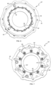
- FIGS. 2 and 3 show the vanes 34 in a minimum-open position, which is set by certain ones of the vanes 34 abutting the spacers 60. More particularly, the spacers are configured and positioned with respect to the vanes so that the desired minimum-open position is achieved when a vane adjacent each of the three spacers 60 is rotated by the unison ring 42 until the vane abuts against the adjacent spacer.
- the spacers 60 also serve to set a maximum-open position of the vanes 34.
- Each spacer includes an extension portion 60E that projects out from the face of the nozzle ring 38 that is adjacent to the vane arms 40.
- the spacers are configured and positioned so that the extension portions 60E set the maximum-open position of the vanes when a vane arm 40 adjacent each extension portion 60E is rotated by the unison ring until it runs up against the extension portion.
- the spacers 60 thus are multi-tasking components that allow the variable-vane unit 50 to be simplified in terms of number of components and number of manufacturing and assembly steps. Because the spacers serve not only as spacers but also as hard stops for the vane mechanism, the hard stop pins normally required for limiting the vane travel are eliminated, along with the manufacturing and assembly steps associated with their use.
- FIGS. 6 through 9 illustrate a second embodiment of a variable-vane unit 50' in accordance with the invention.
- the spacers 60' operate upon the vanes 34 only, not on the vane arms 40.
- one of the three spacers is positioned so that the desired minimum-open position is achieved when a vane 34 adjacent that spacer is rotated by the unison ring 42 until the vane abuts the spacer.
- the other two spacers play no role in setting the minimum-open position.
- the other two spacers 60' are positioned so that the desired maximum-open position is achieved when a vane 34 adjacent each of those two spacers is rotated by the unison ring 42 until the vane abuts the adjacent spacer.
- any given spacer can serve as a hard stop for a vane or a vane arm for either the minimum-open position or the maximum-open position. It is not essential, however, that every spacer serve as a hard stop.
Description
- The present invention relates to turbochargers having a variable-nozzle turbine in which an array of movable vanes is disposed in the nozzle of the turbine for regulating exhaust gas flow into the turbine.
- An exhaust gas-driven turbocharger is a device used in conjunction with an internal combustion engine for increasing the power output of the engine by compressing the air that is delivered to the air intake of the engine to be mixed with fuel and burned in the engine. A turbocharger comprises a compressor wheel mounted on one end of a shaft in a compressor housing and a turbine wheel mounted on the other end of the shaft in a turbine housing. Typically the turbine housing is formed separately from the compressor housing, and there is yet another center housing connected between the turbine and compressor housings for containing bearings for the shaft. The turbine housing defines a generally annular chamber that surrounds the turbine wheel and that receives exhaust gas from an engine. The turbine assembly includes a nozzle that leads from the chamber into the turbine wheel. The exhaust gas flows from the chamber through the nozzle to the turbine wheel and the turbine wheel is driven by the exhaust gas. The turbine thus extracts power from the exhaust gas and drives the compressor. The compressor receives ambient air through an inlet of the compressor housing and the air is compressed by the compressor wheel and is then discharged from the housing to the engine air intake.
- One of the challenges in boosting engine performance with a turbocharger is achieving a desired amount of engine power output throughout the entire operating range of the engine. It has been found that this objective is often not readily attainable with a fixed-geometry turbocharger, and hence variable-geometry turbochargers have been developed with the objective of providing a greater degree of control over the amount of boost provided by the turbocharger.
- One type of variable-geometry turbocharger is the variable-nozzle turbocharger (VNT), which includes an array of variable vanes in the turbine nozzle. The vanes are rotatably mounted to a nozzle ring, which forms one wall of the nozzle. The opposite wall of the nozzle is formed by an insert that fits into a space defined in the turbine housing. The axial spacing between the nozzle ring and the insert is maintained by several spacers that are connected between these parts. The vanes are connected to a mechanism that enables the setting angles of the vanes to be varied. Changing the setting angles of the vanes has the effect of changing the effective flow area in the turbine nozzle, and thus the flow of exhaust gas to the turbine wheel can be regulated by controlling the vane positions. In this manner, the power output of the turbine can be regulated, which allows engine power output to be controlled to a greater extent than is generally possible with a fixed-geometry turbocharger.
-
EP 3 401 505 A1 ,WO 2008/118833 A1 ,EP 2 351 911 A2 andUS 2018/328281 A1 disclose examples of variable-nozzle turbochargers. - The present disclosure is directed toward improvements in variable-nozzle turbines of the type noted above.
- The present disclosure describes a variable-nozzle turbocharger having a variable-nozzle turbine in which a plurality of spacers are employed for spacing the nozzle ring from the insert. In accordance with the invention, the spacers serve the additional role of hard stops that limit the rotatable travel of the vanes in both the open and close directions, thereby eliminating the need for separate hard stop components such as pins or the like In accordance with the invention, a turbocharger having a variable.nozzle turbine comprises:
- a turbine assembly comprising a turbine housing and a turbine wheel mounted in the turbine housing and connected to a rotatable shaft for rotation therewith, the turbine housing defining a chamber surrounding the turbine wheel for receiving exhaust gas and for supplying the exhaust gas to the turbine wheel, the turbine assembly defining a nozzle leading from the chamber generally radially inwardly to the turbine wheel;
- a compressor assembly comprising a compressor housing and a compressor wheel mounted in the compressor housing and connected to the rotatable shaft for rotation therewith;
- a center housing connected between the compressor housing and the turbine housing;
- a variable-vane assembly comprising a generally annular nozzle ring and an array of vanes circumferentially spaced about the nozzle ring adjacent a first face thereof, the vanes being disposed in the nozzle such that exhaust gas flows between the vanes to the turbine wheel, each vane being rotatably mounted to the nozzle ring and connected to a rotatable actuator ring such that rotation of the actuator ring rotates the vanes for regulating exhaust gas flow to the turbine wheel;
- an insert disposed in the turbine housing, the insert defining a nozzle portion axially spaced from the first face of the nozzle ring such that the vanes extend between the nozzle ring and the nozzle portion; and
- a plurality of spacers connected between the nozzle portion of the insert and the nozzle ring for maintaining an axial spacing between the nozzle portion of the insert and the nozzle ring;
- wherein the spacers are structured and arranged to mechanically stop the vanes from rotating in one direction past a maximum-open position and to mechanically stop the vanes from rotating in an opposite direction past a minimum-open position.
- In some embodiments of the invention, each vane is joined to an axle that passes through a bearing aperture in the nozzle ring, wherein an end of each axle projects out from the bearing aperture at a second face of the nozzle ring opposite from said first face and is joined to a vane arm. The vane arms engage the actuator ring such that rotation of the actuator ring causes the vane arms to pivot about the axles and thereby rotate the vanes. In accordance with said embodiments, at least one of said spacers has an extension portion that projects out from the second face of the nozzle ring and is structured and arranged to be abutted by one of said vane arms to mechanically stop the vanes from rotating in said one direction past said maximum-open position.
- Optionally, multiple ones of said spacers can have such extension portions that project out from the second face of the nozzle ring and are structured and arranged to be abutted respectively by multiple ones of said vane arms to mechanically stop the vanes from rotating in said one direction past said maximum-open position.
- In an embodiment of the invention, at least one of said spacers is structured and arranged to be abutted by one of said vanes to mechanically stop the vanes from rotating in said opposite direction past said minimum-open position. Optionally, multiple ones of said spacers can be structured and arranged to be abutted respectively by multiple ones of said vanes to mechanically stop the vanes from rotating in said opposite direction past said minimum-open position. In such embodiments, one of said spacers can be structured and arranged to be abutted by another one of said vanes to mechanically stop the vanes from rotating in said one direction past said maximum-open position.
- Having thus described the invention in general terms, reference will now be made to the accompanying drawings, which are not necessarily drawn to scale, and wherein:
-
FIG. 1 is a cross-sectional view of a turbocharger in accordance with one embodiment of the invention; -
FIG. 2 is an isometric view of a variable-vane assembly for the turbocharger in accordance with one embodiment of the invention, viewed from a vane side of the assembly, the variable-vane assembly being shown with the vanes in a minimum-open position; -
FIG. 3 is an isometric view of the variable-vane assembly ofFIG. 2 , viewed from an opposite side of the assembly; -
FIG. 4 is an isometric view similar toFIG. 2 , but with the vanes in a maximum-open position; -
FIG. 5 is an isometric view similar toFIG. 3 , but with the vanes in the maximum-open position; -
FIG. 6 is a plan view of a variable-vane assembly in accordance with another embodiment of the invention, as viewed from a vane side of the assembly, with the vanes shown in a minimum-open position; and -
FIG. 7 is a plan view of the assembly ofFIG. 6 , as viewed from an opposite side of the assembly; -
FIG. 8 shows the variable-vane assembly ofFIG. 6 but with the vanes in a maximum-open position, as viewed from the vane side of the assembly; and -
FIG. 9 shows the variable-vane assembly ofFIG. 6 with the vanes in the maximum-open position, as viewed from the opposite side of the assembly. - The present inventions now will be described more fully hereinafter with reference to the accompanying drawings, in which some but not all embodiments of the inventions are shown. Indeed, these inventions may be embodied in many different forms and should not be construed as limited to the embodiments set forth herein. Like numbers refer to like elements throughout.
- A
turbocharger 10 in accordance with one embodiment of the invention is illustrated in cross-sectional view inFIG. 1 . The turbocharger comprises acompressor 12 having a compressor wheel orimpeller 14 mounted in a compressor housing 16 on one end of arotatable shaft 18. The shaft is supported inbearings 19 mounted in acenter housing 20 of the turbocharger. Theshaft 18 is rotated by aturbine wheel 22 mounted on the other end of theshaft 18 from the compressor wheel, thereby rotatably driving the compressor wheel, which compresses air drawn in through the compressor inlet and delivers the compressed air to the intake of an internal combustion engine (not shown) for boosting the performance of the engine. - The turbocharger also includes a
turbine housing 24 that houses theturbine wheel 22. The turbine housing defines a generallyannular chamber 26 that surrounds the turbine wheel and that receives exhaust gas from the internal combustion engine for driving the turbine wheel. The exhaust gas is directed from thechamber 26 generally radially inwardly through aturbine nozzle 28 to theturbine wheel 22. As the exhaust gas flow through the passages between theblades 30 of the turbine wheel, the gas is expanded to a lower pressure, and the gas discharged from the wheel exits the turbine housing through a generally axial bore 32 therein. - Reference is now made to
FIGS. 2 through 5 , which depict a subassembly of the turbocharger, comprising a variable-vane assembly for theturbine nozzle 28 for varying the cross-sectional flow area through the nozzle so as to regulate flow into the turbine wheel. The assembly includes a plurality ofvanes 34 that are circumferentially spaced about the nozzle. Each vane is affixed to anaxle 36 that passes through an aperture in a generallyannular nozzle ring 38 that is mounted coaxially with respect to theturbine wheel 22. Eachaxle 36 is rotatable about its axis for rotating the attached vane. Thenozzle ring 38 forms one wall of the flow passage of thenozzle 28. Each of theaxles 36 has avane arm 40 affixed to an end of the axle that protrudes out from thenozzle ring 38. Thevane arms 40 are engaged by a generally annular unison ring 42 (also referred to herein as an actuator ring) that is rotatable about its axis and that is coaxial with thenozzle ring 38.Guides 39 mounted on thenozzle ring 38 are engaged with the inner perimeter of the unison ring for guiding its rotational movement so that it remains substantially concentric with the nozzle ring, and for preventing the unison ring from moving in the axial direction away from the nozzle ring. An actuator (not shown) is connected to theunison ring 42 for rotating it about its axis. When the unison ring is rotated, thevane arms 40 are rotated to cause theaxles 36 to rotate about their axes, thereby rotating thevanes 34 so as to vary the cross-sectional flow area through thenozzle 28. - In the illustrated embodiment, the variable vane mechanism is provided in the form of a
unit 50 that is installable into and removable from the turbocharger. Theunit 50 comprises thenozzle ring 38,vanes 34,axles 36,vane arms 40, andunison ring 42. The unit works in cooperation with an insert 52 (FIG. 1 ) that is installed in theturbine housing 24. The insert defines anozzle portion 56 that is axially spaced from thenozzle ring 38 such that thevanes 34 extend between thenozzle ring 38 and thenozzle portion 56. - The turbocharger includes a heat shroud 80 (
FIG. 1 ) that is captively retained between thenozzle ring 38 and thecenter housing 20 when the variable-vane unit 50 is installed into the turbocharger. Theheat shroud 80 provides sealing between the nozzle ring and center housing to prevent hot exhaust gas from migrating between these parts into the cavity in which thevane arms 40 andunison ring 42 are disposed. Theheat shroud 80 advantageously is a resiliently elastic material such as spring steel or the like, and the shroud is configured so that it is compressed in the axial direction between thenozzle ring 38 and thecenter housing 20 so that the restoring force of the shroud urges thenozzle ring 38 axially toward the turbine wheel 22 (to the right inFIG. 1 ). - A plurality of
spacers 60 are mounted to thenozzle ring 38 and project toward thenozzle portion 56 of theinsert 52. Ends of thespacers 60 abut the nozzle portion 56 (as urged by theresilient heat shroud 80 described in the preceding paragraph) for maintaining the desired axial spacing between thenozzle portion 56 of the insert and thenozzle ring 38. The spacers thereby help ensure that there are small axial clearances between the ends of thevanes 34 and thenozzle ring 38 on one end and thenozzle portion 56 on the other end. The axial spacing set by thespacers 60 is designed to ensure that those clearance do not become too small, which could cause binding of the vanes, or too large, which could compromise turbine efficiency. - With reference to
FIGS. 2 and 3 , in accordance with an embodiment of the invention, thespacers 60 serve not only to set the axial spacing between thenozzle ring 38 and theinsert nozzle portion 56, but also acts as hard stops for the vane assembly to limit how far closed thevanes 34 can move.FIGS. 2 and 3 show thevanes 34 in a minimum-open position, which is set by certain ones of thevanes 34 abutting thespacers 60. More particularly, the spacers are configured and positioned with respect to the vanes so that the desired minimum-open position is achieved when a vane adjacent each of the threespacers 60 is rotated by theunison ring 42 until the vane abuts against the adjacent spacer. - With reference to
FIGS. 4 and 5 , thespacers 60 also serve to set a maximum-open position of thevanes 34. Each spacer includes anextension portion 60E that projects out from the face of thenozzle ring 38 that is adjacent to thevane arms 40. The spacers are configured and positioned so that theextension portions 60E set the maximum-open position of the vanes when avane arm 40 adjacent eachextension portion 60E is rotated by the unison ring until it runs up against the extension portion. - The
spacers 60 thus are multi-tasking components that allow the variable-vane unit 50 to be simplified in terms of number of components and number of manufacturing and assembly steps. Because the spacers serve not only as spacers but also as hard stops for the vane mechanism, the hard stop pins normally required for limiting the vane travel are eliminated, along with the manufacturing and assembly steps associated with their use. - The embodiment of the invention illustrated in
FIGS. 2-5 and described above is only exemplary of one possible way of practicing the invention. The invention is not limited to the details of that embodiment, but can be practiced in many different ways. As another example,FIGS. 6 through 9 illustrate a second embodiment of a variable-vane unit 50' in accordance with the invention. In the second embodiment, thespacers 60' operate upon thevanes 34 only, not on thevane arms 40. Thus, with reference toFIG. 6 , to set the minimum-open vane position, one of the three spacers is positioned so that the desired minimum-open position is achieved when avane 34 adjacent that spacer is rotated by theunison ring 42 until the vane abuts the spacer. The other two spacers play no role in setting the minimum-open position. - With reference to
FIG. 8 , to set the maximum-open position, the other twospacers 60' are positioned so that the desired maximum-open position is achieved when avane 34 adjacent each of those two spacers is rotated by theunison ring 42 until the vane abuts the adjacent spacer. - Other variations of using multi-tasking spacers as hard stops for the vane mechanism are also possible within the scope of the present invention. Any given spacer can serve as a hard stop for a vane or a vane arm for either the minimum-open position or the maximum-open position. It is not essential, however, that every spacer serve as a hard stop.
- Thus, many modifications and other embodiments of the inventions set forth herein will come to mind to one skilled in the art to which these inventions pertain having the benefit of the teachings presented in the foregoing descriptions and the associated drawings. Therefore, it is to be understood that the inventions are not to be limited to the specific embodiments disclosed and that modifications and other embodiments are intended to be included within the scope of the appended claims. Although specific terms are employed herein, they are used in a generic and descriptive sense only and not for purposes of limitation.
Claims (6)
- A turbocharger having a variable-nozzle turbine, comprising:a turbine assembly comprising a turbine housing (24) and a turbine wheel (22) mounted in the turbine housing and connected to a rotatable shaft (18) for rotation therewith, the turbine housing defining a chamber surrounding the turbine wheel for receiving exhaust gas and for supplying the exhaust gas to the turbine wheel, the turbine assembly defining a nozzle leading from the chamber generally radially inwardly to the turbine wheel;a compressor assembly comprising a compressor housing (16) and a compressor wheel (14) mounted in the compressor housing and connected to the rotatable shaft (18) for rotation therewith;a center housing (20) connected between the compressor housing and the turbine housing;a variable-vane assembly comprising a generally annular nozzle ring (38) and an array of vanes (34) circumferentially spaced about the nozzle ring (42) adjacent a first face thereof, the vanes being disposed in the nozzle such that exhaust gas flows between the vanes to the turbine wheel, each vane being rotatably mounted to the nozzle ring and connected to a rotatable actuator ring such that rotation of the actuator ring rotates the vanes for regulating exhaust gas flow to the turbine wheel;an insert (52) disposed in the turbine housing, the insert defining a nozzle portion axially spaced from the first face of the nozzle ring such that the vanes extend between the nozzle ring and the nozzle portion; and characterised bya plurality of spacers (60) connected between the nozzle portion of the insert (52) and the nozzle ring (42) for maintaining an axial spacing between the nozzle portion of the insert and the nozzle ring, wherein the spacers are structured and arranged to mechanically stop the vanes from rotating in one direction past a maximum-open position and to mechanically stop the vanes from rotating in an opposite direction past a minimum-open position.
- The turbocharger of claim 1, wherein each vane (34) is joined to an axle that passes through a bearing aperture in the nozzle ring, wherein an end of each axle projects out from the bearing aperture at a second face of the nozzle ring opposite from said first face and is joined to a vane arm, wherein the vane arms engage the actuator ring such that rotation of the actuator ring causes the vane arms to pivot about the axles and thereby rotate the vanes, and wherein at least one of said spacers (60) has an extension portion that projects out from the second face of the nozzle ring and is structured and arranged to be abutted by one of said vane arms to mechanically stop the vanes from rotating in said one direction past said maximum-open position.
- The turbocharger of claim 2, wherein multiple ones of said spacers (60) have extension portions that project out from the second face of the nozzle ring and are structured and arranged to be abutted respectively by multiple ones of said vane arms to mechanically stop the vanes from rotating in said one direction past said maximum-open position.
- The turbocharger of claim 1, wherein at least one of said spacers (60) is structured and arranged to be abutted by one of said vanes to mechanically stop the vanes from rotating in said opposite direction past said minimum-open position.
- The turbocharger of claim 4, wherein multiple ones of said spacers (60) are structured and arranged to be abutted respectively by multiple ones of said vanes to mechanically stop the vanes from rotating in said opposite direction past said minimum-open position.
- The turbocharger of claim 4, wherein one of said spacers (60) is structured and arranged to be abutted by another one of said vanes to mechanically stop the vanes from rotating in said one direction past said maximum-open position.
Applications Claiming Priority (1)
| Application Number | Priority Date | Filing Date | Title |
|---|---|---|---|
| US16/351,435 US10927701B2 (en) | 2019-03-12 | 2019-03-12 | Turbocharger having variable-vane turbine nozzle including spacers that also serve as hard stops for the vanes |
Publications (2)
| Publication Number | Publication Date |
|---|---|
| EP3708780A1 EP3708780A1 (en) | 2020-09-16 |
| EP3708780B1 true EP3708780B1 (en) | 2023-08-16 |
Family
ID=69187714
Family Applications (1)
| Application Number | Title | Priority Date | Filing Date |
|---|---|---|---|
| EP20153212.4A Active EP3708780B1 (en) | 2019-03-12 | 2020-01-22 | Turbocharger having variable-vane turbine nozzle including spacers that also serve as hard stops for the vanes |
Country Status (3)
| Country | Link |
|---|---|
| US (1) | US10927701B2 (en) |
| EP (1) | EP3708780B1 (en) |
| CN (1) | CN111691971A (en) |
Families Citing this family (3)
| Publication number | Priority date | Publication date | Assignee | Title |
|---|---|---|---|---|
| US11674409B2 (en) * | 2021-03-31 | 2023-06-13 | Garrett Transportation I Inc. | Turbocharger with vaned turbine nozzle, and method of assembling same |
| US11506074B1 (en) * | 2021-12-01 | 2022-11-22 | Garrett Transportation I Inc. | Turbocharger having variable-vane turbine nozzle including arrangement for locking the vanes in fully open position |
| DE102021134071A1 (en) * | 2021-12-21 | 2023-06-22 | Borgwarner Inc. | RADIAL TURBINE WITH VTG GUIDE GRID |
Family Cites Families (14)
| Publication number | Priority date | Publication date | Assignee | Title |
|---|---|---|---|---|
| US4804316A (en) * | 1985-12-11 | 1989-02-14 | Allied-Signal Inc. | Suspension for the pivoting vane actuation mechanism of a variable nozzle turbocharger |
| DE10262006B4 (en) * | 2002-03-05 | 2005-09-22 | Borgwarner Turbo Systems Gmbh | Turbocharger for vehicles with improved suspension for the actuating mechanism of the variable nozzles |
| EP1418311B1 (en) * | 2002-11-11 | 2007-01-17 | BorgWarner Inc. | Variable geometry vanes array for a turbocharger |
| US7670107B2 (en) * | 2007-03-26 | 2010-03-02 | Honeywell International Inc. | Variable-vane assembly having fixed axial-radial guides and fixed radial-only guides for unison ring |
| DE102008053169A1 (en) * | 2008-10-24 | 2010-04-29 | Bosch Mahle Turbo Systems Gmbh & Co. Kg | loader |
| US9017017B2 (en) * | 2009-04-10 | 2015-04-28 | Honeywell Internatonal Inc. | Variable-vane assembly having fixed guide pins for unison ring |
| US8668443B2 (en) | 2010-01-08 | 2014-03-11 | Honeywell International Inc. | Variable-vane assembly having unison ring guided radially by rollers and fixed members, and restrained axially by one or more fixed axial stops |
| JP5193346B2 (en) * | 2011-09-28 | 2013-05-08 | 三菱重工業株式会社 | Variable displacement exhaust turbocharger with variable nozzle mechanism |
| DE102012219355A1 (en) * | 2012-10-23 | 2014-04-24 | Bosch Mahle Turbo Systems Gmbh & Co. Kg | Vane arrangement for exhaust gas turbocharger of motor car, has guide vanes arranged between cover disk and blade ring, where cover disk is made of ceramic material having high heat conductivity |
| US9765687B2 (en) * | 2014-04-29 | 2017-09-19 | Honeywell International Inc. | Turbocharger with variable-vane turbine nozzle having a gas pressure-responsive vane clearance control member |
| US10302011B2 (en) * | 2015-11-23 | 2019-05-28 | Garrett Transportation I Inc. | Exhaust gas variable turbine assembly |
| JP6583534B2 (en) * | 2016-03-03 | 2019-10-02 | 株式会社Ihi | Nozzle drive mechanism, supercharger, and variable capacity supercharger |
| US11111854B2 (en) | 2017-05-09 | 2021-09-07 | Garrett Transportation 1 Inc. | Turbocharger having a meridionally divided turbine housing and a variable turbine nozzle |
| US10900415B2 (en) * | 2017-05-09 | 2021-01-26 | Garrett Transportation I Inc. | Turbocharger having a meridionally divided turbine housing and a variable turbine nozzle |
-
2019
- 2019-03-12 US US16/351,435 patent/US10927701B2/en active Active
-
2020
- 2020-01-22 EP EP20153212.4A patent/EP3708780B1/en active Active
- 2020-03-12 CN CN202010170746.2A patent/CN111691971A/en active Pending
Also Published As
| Publication number | Publication date |
|---|---|
| US20200291811A1 (en) | 2020-09-17 |
| US10927701B2 (en) | 2021-02-23 |
| CN111691971A (en) | 2020-09-22 |
| EP3708780A1 (en) | 2020-09-16 |
Similar Documents
| Publication | Publication Date | Title |
|---|---|---|
| CN101943030B (en) | Variable geometry vane assembly for a turbocharger | |
| EP1945928B1 (en) | Turbocharger and variable-nozzle cartridge therefor | |
| EP3708780B1 (en) | Turbocharger having variable-vane turbine nozzle including spacers that also serve as hard stops for the vanes | |
| EP2535524B1 (en) | Turbocharger variable-nozzle assembly with vane sealing ring | |
| EP2171220B1 (en) | Turbocharger variable-vane assembly having fixed axial-radial guides for unison ring | |
| EP2227620B1 (en) | Variable nozzle for a turbocharger, having nozzle ring located by radial members | |
| CN106121737B (en) | Turbocharger with variable vane turbine nozzle with integrated bypass mechanism | |
| EP2594745B1 (en) | Turbocharger variable-nozzle assembly with vane sealing arrangement | |
| EP3282097B1 (en) | Variable-nozzle turbine with means for radial locating of variable-nozzle cartridge | |
| US10900415B2 (en) | Turbocharger having a meridionally divided turbine housing and a variable turbine nozzle | |
| EP3026220B1 (en) | Turbocharger variable-vane cartridge with nozzle ring and pipe secured by two-piece self-centering spacers | |
| EP3392466B1 (en) | Variable-nozzle turbine with means for radial locating of variable-nozzle cartridge | |
| EP2035673B1 (en) | Variable stator blade mechanism for turbochargers | |
| EP2320033B1 (en) | Variable geometry turbocharger with guide pins | |
| EP2730750B1 (en) | Turbocharger and variable-nozzle cartridge therefor | |
| EP3680456B1 (en) | Turbocharger with variable-nozzle cartridge, including resilient heat shield assembly to locate the cartridge axially | |
| EP4067626A1 (en) | Turbocharger with vaned turbine nozzle, and method of assembling same | |
| US11506074B1 (en) | Turbocharger having variable-vane turbine nozzle including arrangement for locking the vanes in fully open position | |
| EP3569827B1 (en) | Variable diffuser having a respective penny for each vane |
Legal Events
| Date | Code | Title | Description |
|---|---|---|---|
| PUAI | Public reference made under article 153(3) epc to a published international application that has entered the european phase |
Free format text: ORIGINAL CODE: 0009012 |
|
| STAA | Information on the status of an ep patent application or granted ep patent |
Free format text: STATUS: REQUEST FOR EXAMINATION WAS MADE |
|
| 17P | Request for examination filed |
Effective date: 20200122 |
|
| AK | Designated contracting states |
Kind code of ref document: A1 Designated state(s): AL AT BE BG CH CY CZ DE DK EE ES FI FR GB GR HR HU IE IS IT LI LT LU LV MC MK MT NL NO PL PT RO RS SE SI SK SM TR |
|
| AX | Request for extension of the european patent |
Extension state: BA ME |
|
| RIC1 | Information provided on ipc code assigned before grant |
Ipc: F01D 17/16 20060101ALI20230213BHEP Ipc: F01D 9/02 20060101AFI20230213BHEP |
|
| GRAP | Despatch of communication of intention to grant a patent |
Free format text: ORIGINAL CODE: EPIDOSNIGR1 |
|
| STAA | Information on the status of an ep patent application or granted ep patent |
Free format text: STATUS: GRANT OF PATENT IS INTENDED |
|
| INTG | Intention to grant announced |
Effective date: 20230329 |
|
| P01 | Opt-out of the competence of the unified patent court (upc) registered |
Effective date: 20230424 |
|
| GRAS | Grant fee paid |
Free format text: ORIGINAL CODE: EPIDOSNIGR3 |
|
| GRAA | (expected) grant |
Free format text: ORIGINAL CODE: 0009210 |
|
| STAA | Information on the status of an ep patent application or granted ep patent |
Free format text: STATUS: THE PATENT HAS BEEN GRANTED |
|
| AK | Designated contracting states |
Kind code of ref document: B1 Designated state(s): AL AT BE BG CH CY CZ DE DK EE ES FI FR GB GR HR HU IE IS IT LI LT LU LV MC MK MT NL NO PL PT RO RS SE SI SK SM TR |
|
| REG | Reference to a national code |
Ref country code: CH Ref legal event code: EP Ref country code: DE Ref legal event code: R096 Ref document number: 602020015653 Country of ref document: DE |
|
| REG | Reference to a national code |
Ref country code: IE Ref legal event code: FG4D |
|
| REG | Reference to a national code |
Ref country code: LT Ref legal event code: MG9D |
|
| REG | Reference to a national code |
Ref country code: NL Ref legal event code: MP Effective date: 20230816 |
|
| REG | Reference to a national code |
Ref country code: AT Ref legal event code: MK05 Ref document number: 1600252 Country of ref document: AT Kind code of ref document: T Effective date: 20230816 |
|
| PG25 | Lapsed in a contracting state [announced via postgrant information from national office to epo] |
Ref country code: GR Free format text: LAPSE BECAUSE OF FAILURE TO SUBMIT A TRANSLATION OF THE DESCRIPTION OR TO PAY THE FEE WITHIN THE PRESCRIBED TIME-LIMIT Effective date: 20231117 |
|
| PG25 | Lapsed in a contracting state [announced via postgrant information from national office to epo] |
Ref country code: IS Free format text: LAPSE BECAUSE OF FAILURE TO SUBMIT A TRANSLATION OF THE DESCRIPTION OR TO PAY THE FEE WITHIN THE PRESCRIBED TIME-LIMIT Effective date: 20231216 |
|
| PG25 | Lapsed in a contracting state [announced via postgrant information from national office to epo] |
Ref country code: SE Free format text: LAPSE BECAUSE OF FAILURE TO SUBMIT A TRANSLATION OF THE DESCRIPTION OR TO PAY THE FEE WITHIN THE PRESCRIBED TIME-LIMIT Effective date: 20230816 Ref country code: RS Free format text: LAPSE BECAUSE OF FAILURE TO SUBMIT A TRANSLATION OF THE DESCRIPTION OR TO PAY THE FEE WITHIN THE PRESCRIBED TIME-LIMIT Effective date: 20230816 Ref country code: PT Free format text: LAPSE BECAUSE OF FAILURE TO SUBMIT A TRANSLATION OF THE DESCRIPTION OR TO PAY THE FEE WITHIN THE PRESCRIBED TIME-LIMIT Effective date: 20231218 Ref country code: NO Free format text: LAPSE BECAUSE OF FAILURE TO SUBMIT A TRANSLATION OF THE DESCRIPTION OR TO PAY THE FEE WITHIN THE PRESCRIBED TIME-LIMIT Effective date: 20231116 Ref country code: NL Free format text: LAPSE BECAUSE OF FAILURE TO SUBMIT A TRANSLATION OF THE DESCRIPTION OR TO PAY THE FEE WITHIN THE PRESCRIBED TIME-LIMIT Effective date: 20230816 Ref country code: LV Free format text: LAPSE BECAUSE OF FAILURE TO SUBMIT A TRANSLATION OF THE DESCRIPTION OR TO PAY THE FEE WITHIN THE PRESCRIBED TIME-LIMIT Effective date: 20230816 Ref country code: LT Free format text: LAPSE BECAUSE OF FAILURE TO SUBMIT A TRANSLATION OF THE DESCRIPTION OR TO PAY THE FEE WITHIN THE PRESCRIBED TIME-LIMIT Effective date: 20230816 Ref country code: IS Free format text: LAPSE BECAUSE OF FAILURE TO SUBMIT A TRANSLATION OF THE DESCRIPTION OR TO PAY THE FEE WITHIN THE PRESCRIBED TIME-LIMIT Effective date: 20231216 Ref country code: HR Free format text: LAPSE BECAUSE OF FAILURE TO SUBMIT A TRANSLATION OF THE DESCRIPTION OR TO PAY THE FEE WITHIN THE PRESCRIBED TIME-LIMIT Effective date: 20230816 Ref country code: GR Free format text: LAPSE BECAUSE OF FAILURE TO SUBMIT A TRANSLATION OF THE DESCRIPTION OR TO PAY THE FEE WITHIN THE PRESCRIBED TIME-LIMIT Effective date: 20231117 Ref country code: FI Free format text: LAPSE BECAUSE OF FAILURE TO SUBMIT A TRANSLATION OF THE DESCRIPTION OR TO PAY THE FEE WITHIN THE PRESCRIBED TIME-LIMIT Effective date: 20230816 Ref country code: AT Free format text: LAPSE BECAUSE OF FAILURE TO SUBMIT A TRANSLATION OF THE DESCRIPTION OR TO PAY THE FEE WITHIN THE PRESCRIBED TIME-LIMIT Effective date: 20230816 |
|
| PG25 | Lapsed in a contracting state [announced via postgrant information from national office to epo] |
Ref country code: PL Free format text: LAPSE BECAUSE OF FAILURE TO SUBMIT A TRANSLATION OF THE DESCRIPTION OR TO PAY THE FEE WITHIN THE PRESCRIBED TIME-LIMIT Effective date: 20230816 |