EP2213839A2 - Segmented ceramic component for a gas turbine engine - Google Patents
Segmented ceramic component for a gas turbine engine Download PDFInfo
- Publication number
- EP2213839A2 EP2213839A2 EP10250001A EP10250001A EP2213839A2 EP 2213839 A2 EP2213839 A2 EP 2213839A2 EP 10250001 A EP10250001 A EP 10250001A EP 10250001 A EP10250001 A EP 10250001A EP 2213839 A2 EP2213839 A2 EP 2213839A2
- Authority
- EP
- European Patent Office
- Prior art keywords
- segments
- segment
- airfoil
- platform
- segmented component
- Prior art date
- Legal status (The legal status is an assumption and is not a legal conclusion. Google has not performed a legal analysis and makes no representation as to the accuracy of the status listed.)
- Granted
Links
Images




Classifications
-
- F—MECHANICAL ENGINEERING; LIGHTING; HEATING; WEAPONS; BLASTING
- F01—MACHINES OR ENGINES IN GENERAL; ENGINE PLANTS IN GENERAL; STEAM ENGINES
- F01D—NON-POSITIVE DISPLACEMENT MACHINES OR ENGINES, e.g. STEAM TURBINES
- F01D5/00—Blades; Blade-carrying members; Heating, heat-insulating, cooling or antivibration means on the blades or the members
- F01D5/12—Blades
- F01D5/28—Selecting particular materials; Particular measures relating thereto; Measures against erosion or corrosion
- F01D5/284—Selection of ceramic materials
-
- F—MECHANICAL ENGINEERING; LIGHTING; HEATING; WEAPONS; BLASTING
- F01—MACHINES OR ENGINES IN GENERAL; ENGINE PLANTS IN GENERAL; STEAM ENGINES
- F01D—NON-POSITIVE DISPLACEMENT MACHINES OR ENGINES, e.g. STEAM TURBINES
- F01D5/00—Blades; Blade-carrying members; Heating, heat-insulating, cooling or antivibration means on the blades or the members
- F01D5/30—Fixing blades to rotors; Blade roots ; Blade spacers
- F01D5/3007—Fixing blades to rotors; Blade roots ; Blade spacers of axial insertion type
- F01D5/3015—Fixing blades to rotors; Blade roots ; Blade spacers of axial insertion type with side plates
-
- F—MECHANICAL ENGINEERING; LIGHTING; HEATING; WEAPONS; BLASTING
- F05—INDEXING SCHEMES RELATING TO ENGINES OR PUMPS IN VARIOUS SUBCLASSES OF CLASSES F01-F04
- F05D—INDEXING SCHEME FOR ASPECTS RELATING TO NON-POSITIVE-DISPLACEMENT MACHINES OR ENGINES, GAS-TURBINES OR JET-PROPULSION PLANTS
- F05D2240/00—Components
- F05D2240/80—Platforms for stationary or moving blades
-
- Y—GENERAL TAGGING OF NEW TECHNOLOGICAL DEVELOPMENTS; GENERAL TAGGING OF CROSS-SECTIONAL TECHNOLOGIES SPANNING OVER SEVERAL SECTIONS OF THE IPC; TECHNICAL SUBJECTS COVERED BY FORMER USPC CROSS-REFERENCE ART COLLECTIONS [XRACs] AND DIGESTS
- Y02—TECHNOLOGIES OR APPLICATIONS FOR MITIGATION OR ADAPTATION AGAINST CLIMATE CHANGE
- Y02T—CLIMATE CHANGE MITIGATION TECHNOLOGIES RELATED TO TRANSPORTATION
- Y02T50/00—Aeronautics or air transport
- Y02T50/60—Efficient propulsion technologies, e.g. for aircraft
Definitions
- the present invention is directed to airfoil components for gas turbine engines and, more particularly, to ceramic matrix composite turbine blades, vanes and platforms.
- Gas turbine engines comprise one or more rotating turbines that are used to extract energy from a high velocity and high temperature gas flow produced within the gas turbine engine.
- the turbines are comprised of a plurality of radially extending airfoil blades that are connected at their inner diameter ends to a rotor, which is connected to a shaft that rotates within the engine as the blades interact with the gas flow.
- the rotor typically comprises a disk having a plurality of axial retention slots that receive mating root portions of the blades to prevent radial dislodgment.
- Blades typically also include integral inner diameter platforms that prevent the high temperature gases from escaping through the radial retention slots.
- a plurality of radially extending stationary airfoil vanes which are typically supported by inner and outer diameter shrouds that are suspended from an outer engine case and supported by an inner structure, respectively.
- the turbine blades and vanes are subjected to high heat from the gas. Additionally, the blades are subjected to high stresses from rotational forces. It is, therefore, a constant design challenge to develop materials for turbine blades and vanes that are more heat resistant to reduce cooling demands, and lighter to increase propulsive efficiencies in aircraft engines.
- CMC ceramic matrix composite
- CMC material comprises a ceramic fabric that is infused with a liquid ceramic matrix.
- the ceramic fabric is preformed to a desired shape and the matrix solidifies within the fabric to produce a part having the lightweight and heat resistance characteristics of the matrix and the strength characteristics of the fabric.
- Production of thick CMC material parts is constrained because of manufacturing limitations in infusing the liquid matrix into deep layering of the preformed fabric. Inadequately infused liquid matrix produces porosity within the component that limits the heat transfer capabilities within the matrix and provides an initiation point for crack propagation.
- CMC material weigh approximately one third of the weight of typical metal alloys used for turbine components, while haying much higher temperature limitations.
- production methods have been developed that attempt to overcome the aforementioned manufacturing issues.
- previous attempts at producing CMC material components have resulted in complex designs that limit the benefits of using CMC material in turbine blades.
- one method of producing a vane involves radially stacking numerous layers of CMC material in a radial direction to obtain an airfoil shape. The stack is compressed with mechanical tensioning means to obtain the desired tensile strength and to prevent the layers from separating.
- the mechanical tensioning means typically comprises threaded fasteners fabricated from an alloy that requires cooling, thus limiting the temperature benefits of using CMC material in a hot section of a gas turbine engine.
- the present invention is directed to a segmented component for use with a gas turbine engine.
- the segmented component comprises a radially extending gas path portion.
- the gas path portion is for interacting with gas flow from the gas turbine engine.
- the component is divided into axially aligned segments comprising a forward segment, an aft segment, and a plurality of middle segments disposed between the forward segment and the aft segment.
- the middle segments comprise radially elongate ceramic matrix composite material plates.
- the gas path portion comprises an airfoil for a turbine blade.
- the gas path portion comprises a removable platform for a turbine blade.
- the gas path portion comprises an airfoil for a turbine vane.
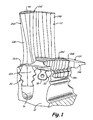
- FIG. 1 shows a cut-away perspective view of a rotor disk having radial retention slots connected with segmented ceramic matrix composite (CMC) turbine blade components of the present invention.
- CMC ceramic matrix composite
- FIG. 2 shows an assembled view of segments from a removable CMC blade airfoil of FIG. 1 .
- FIG. 3 shows an assembled view of segments from a removable CMC blade platform of FIG. 1 .
- FIG. 4 shows a partially exploded view of the removable CMC blade platform segments of FIG. 3 .
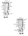
- FIG. 5A shows a CMC blade platform segment of FIG. 4 fabricated from uni-directional ceramic fibers.
- FIG. 5B shows a CMC blade platform segment of FIG. 4 fabricated from bi-directional fibers.
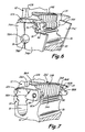
- FIG. 6 shows a partially cut away view of an embodiment of a retention mechanism for use with the removable segmented CMC blade platform of FIGS. 3 and 4 .
- FIG. 7 shows another embodiment of a retention mechanism for use with a removable CMC blade platform of the present invention.
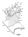
- FIG. 8 shows an embodiment of a stationary segmented CMC vane having inner and outer diameter shrouds supported by a tongue and groove means.
- FIG. 9 shows another embodiment of a stationary segmented CMC vane having inner and outer diameter shrouds supported by retention lug means.
- FIG. 10 shows a cut away view of the stationary segmented CMC vane of FIG. 9 showing a retention lug interacting with retention tabs at an outer diameter shroud.
- FIG. 1 shows a cut-away perspective view of rotor 10 connected to segmented ceramic matrix composite (CMC) material rotor blade components 12 and 14 of the present invention.
- Rotor 10 comprises an annular body, such as a disk, that is configured to rotate about an axial centerline within a gas turbine engine.
- Rotor 10 includes an inner diameter configured to be connected to a shaft in a gas turbine engine in any conventional manner, and an outer diameter configured to connect to segmented CMC blade 12 and segmented CMC platform 14 at retention slots 16 and 18, respectively.
- Blade 12 and platform 14 each include a root portion and a gas path portion.
- blade 12 includes blade root 12A, which is connected to slot 16, and airfoil 12B.
- platform 14 includes platform root 14A, which is connected to slot 18, and stage 14B.
- Blade 12 and platform 14 comprise one cluster of a plurality of clusters that would typically be disposed about the outer periphery of rotor 10.
- the plurality of blades comprises an annular array of airfoils that extend from rotor 10 in a radial direction with respect to the engine centerline.
- the plurality of platforms comprises an annular ring that connects the plurality of airfoils and extends circumferentially around the engine centerline.
- rotor 10 comprises a rotor disk for use in a hot section of the gas turbine engine such as in a low pressure turbine stage or a high pressure turbine stage.
- blade 12 and platform 14 are fabricated from CMC material.
- the present invention maximizes the benefits of the CMC material by first separating blade 12 and platform 14 into separate components, and then dividing each component into longitudinal segments.
- the CMC material is fully densified to achieve optimal heat transfer characteristics, and is oriented to achieve optimal strength characteristics.
- the longitudinal segments of CMC material can be used in hot sections of a gas turbine engine to form various components, such as blades, platforms, vanes and shrouds.
- FIGS. 1 - 7 discuss rotary turbine components, such as blade 12 and platform 14.
- FIGS. 8 and 9 discuss stationary turbine components, such as vanes and shrouds.
- Blade 12 and platform 14 of the present invention are produced as separate pieces to minimize angular geometries within each component that give rise to difficulties in producing CMC material components.
- a plurality of blades 12 and platforms 14 are individually assembled to rotor 10, after which each blade 12 is outfitted with an inner diameter shroud.
- Blade root 12A of blade 12 and platform root 14A of platform 14 are assembled with rotor 10 at slots 16 and 18, respectively.
- Platform slot 18 is positioned adjacent blade slot 16 such that an alternating pattern of slots is formed in the periphery of rotor 10.
- Blade slot 16 is generally larger than platform slot 18 to accommodate the greater radial forces generated by the rotation of blade 12 than the forces generated by platform 14 during rotation of rotor 10.
- Blade root 12A is inserted axially into slot 16 to radially restrain blade 12.
- Root 12A and slot 16 include fir tree engagement 20 in which ribs on root 12A engage channels on slot 16 that permit root 12A to be inserted into slot 16 axially, but that restrain radial movement of blade 12.
- root 14A and slot 18 include dovetail engagement 22 in which hooks on slot 18 engage sidewalls of root 14A that permit root 14A to be inserted into slot 18 axially, but that restrain radial movement of platform 14.
- blade root 12A and platform root 14A may include other radial retention configurations, such as dovetails or fir trees.
- Blade root 12A, platform root 14A, slot 16 and slot 18 are shaped to allow for thermal growth between roots 12A and 14A and slots 16 and 18 from heat generated during operation of the gas turbine.
- Gas path portion 12B of blade 12 and gas path portion 14B of platform 14 extend from root portions 12A and 12B, respectively, to form an airfoil and an inner diameter platform.
- Airfoil 12B extends radially from root 12A and is shaped to include a pressure side and a suction side to extract energy to a flow of gases traveling perpendicular to blades 12.
- Stage 14B extends radially from root 14A and is shaped to provide a seal between a pressure side and a suction side of adjacent blades. Stage 14B seals the base of airfoil 12B and prevents gas flowing over airfoil 14B from entering slots 16 and 18.
- Stage 14B also prevents other fluids, such as cooling air circulated through rotor 10 from entering the flow of gas across airfoil 12B.
- the geometries and curvatures of the abutting surfaces of stage 14B and airfoil 12B are thus mating such that a continuous inner diameter surface is formed near the transition region between root portion 12A and airfoil portion 12B, similar to that of conventional, integral platform blades.
- the present invention splits the platforms from the airfoils along the contour of the blade, rather than splitting an integrated platform between airfoils along a straight line.
- stage 14B and airfoil 12B are selected based on aerodynamic needs, such as the shape of the pressure and suction sides, and radial retention need, such as the shape of engagements 20 and 22.
- the geometries of stage 14B and airfoil 12B are, however, also selected so that they may be easily divided into thin segments to facilitate fabrication from CMC material.
- Blade 12 and platform 14 are further divided into thin, radially extending CMC material segments that better align ceramic fibers within the material and that better enable infusion of a ceramic liquid into the fibers.
- Blade 12 is divided into segments comprising leading edge segment 24A, trailing edge segment 24B and a plurality of middle segments 24C.
- Platform 14 is divided into leading edge segment 26A, trailing edge segment 26B and a plurality of middle segments 26C.
- blade 12 includes seven middle segments and platform 14 includes ten middle segments. In other embodiments, however, other numbers of middle segments can be used.
- FIG. 2 shows an assembled view of segments 24A - 24C from removable CMC blade 12 of FIG. 1 .
- Each segment of blade 12 includes a section of root 12A and airfoil 12B.
- each segment includes a gas path portion configured to impinge the hot gas of the gas turbine engine, and a radial retention portion configured to engage rotor 10.
- Root 12A comprises a generally uniform cross sectional area in the axial direction.
- each segment of root 12A comprises a generally equivalent root portion.
- segments 24A, 24B and 24C are axially aligned, root 12A can be axially inserted into slot 16 so that fir tree engagement 20 is properly seated.
- ribs 28 of root 12A are axially seated within channels 30 of slot 16 to prevent displacement of blade 12 in the radial direction.
- Airfoil 12B includes leading edge 32, trailing edge 34, concave pressure side 36 and convex suction side 38, and extends in a generally arcuate, or airfoil shape, manner in the axial direction. Airfoil 12B also extends generally radially from root 12A such that each of segments 24A, 24B and 24C include a small slice of the airfoil profile.
- Leading edge segment 24A includes a rounded forward surface that forms leading edge 32 and is designed to impinge an oncoming gas stream.
- Leading edge segment 24A also includes a planar rear surface designed to abut one of middle segments 24C.
- Trailing edge segment 24B includes a rounded rear surface that forms trailing edge 34 and is designed to minimize flow separation of the gas stream.
- Trailing edge segment 24B also includes a planar forward surface designed to abut one of middle segments 24C.
- Middle segments 24C include planar forward and rear surfaces so that they can be axially stacked or aligned between leading edge segment 24A and trailing edge segment 24B to complete the shape of an airfoil.
- the sides of middle segments 24C include small segments of pressure side 36 and suction side 38 to complete the airfoil shape.
- each segment can be split into pressure side and suction side segment halves to facilitate assembly with rotor 10 and platform 14, and to produce hollow airfoils to minimize weight.
- leading edge segment 24A includes pressure side 40 and suction side 42, which comprise mating curved segments that meet to form interior cavity 44. Interior cavity 44 can be used to provide cooling air to blade 12 or to reduce the weight of blade 12.
- FIG. 3 shows an assembled view of segments 26A - 26C from removable CMC blade platform 14 of FIG. 1 .
- FIG. 4 which is discussed concurrently with FIG. 3 , shows a partially exploded view of segments 26A - 26C from removable CMC blade platform 14 of FIG. 3 .
- Each segment of platform 14 includes a section of root 14A and stage 14B.
- each segment includes gas path portion configured to impinge the hot gas of the gas turbine engine, and a radial retention portion configured to engage rotor 10.
- Root 14A comprises a generally uniform cross sectional area in the axial direction. As such, each segment of root 14A comprises a generally equivalent root portion.
- root 14A When segments 26A, 26B and 26C are axially aligned, root 14A can be axially inserted into slot 18 so that dovetail engagement 22 ( FIG. 1 ) is properly seated.
- root 12A includes channel 46 that axially receives ribs on slot 16 ( FIG. 1 ) to prevent displacement of platform 14 in the radial direction.
- Root 14A also includes assembly bore 48 that is used to axially assemble and restrain segments 26A - 26C.
- Stage 14B includes leading edge 50, trailing edge 52, convex side 54 and concave side 56, and extends in a generally arcuate manner in the axial direction. Stage 14B also extends generally radially from root 14A such that each of segments 26A, 26B and 26C include a small slice of the arcutate profile. Leading edge segment 26A and trailing edge segment 26B, however, also include axially and tangentially extending portions 58 and 60, respectively, that form forward and aft portions of the inner diameter shroud that encircles blades 12. Leading edge 50 and trailing edge 52 of segments 26A and 26B, respectively, are planar such that they are configured to be adjacent platforms from adjacent turbine stages.
- Convex side 54 has a curvature that is opposite that of pressure side 36 such that convex side 54 and pressure side 36 engage flushly when assembled with rotor 10.
- concave side 56 has a curvature that is opposite that of suction side 38 such that concave side 56 and suction side 38 engage flushly when assembled with rotor 10.
- Middle segments 26C include planar forward and rear surfaces so that they can be axially stacked or aligned between leading edge segment 26A and trailing edge segment 26B to complete the shape of a platform.
- Blade 12 and platform 14 are divided into elongate, thin segments to facilitate processing of the CMC material from which they are produced.
- segments 24A - 24C of blade 12 and segments 26A - 26C of platform 14 are comprised of laminar layers of ceramic fibers such that the fibers provide radial tensile strength to each segment and such that each segment is properly densified with a liquid ceramic matrix.
- Blade 12 and platform 14 are produced from similarly configured CMC plates, the specifics of which are described with reference to middle segment 26C of platform 14 in FIGS. 5A and 5B .
- CMC plates of such a construction are suitable for use in any of segments 24A - 24C and segments 26A - 26C.
- FIG. 5A shows one of CMC blade platform segments 26C of FIG. 4 fabricated from uni-directional ceramic fibers 64.
- FIG. 5B shows one of CMC blade platform segments 26C of FIG. 4 fabricated from bi-directional fibers 66 and 68.
- Segment 26C is comprised of a generally planar plate having through-thickness t . Through-thickness t extends generally in the axial direction when segment 26C is inserted into slot 18 ( FIG. 1 ) of rotor 10.
- Each plate is comprised of ceramic fiber laminar sheets that spans root portion 14A and gas path portion 14B.
- each sheet 70 is comprised of a plurality of ceramic fiber strands 64 that are provided as a uni-directional tape.
- FIG. 5A shows one of CMC blade platform segments 26C of FIG. 4 fabricated from uni-directional ceramic fibers 64.
- FIG. 5B shows one of CMC blade platform segments 26C of FIG. 4 fabricated from bi-directional fibers 66 and 68.
- each sheet 72 is comprised of a plurality of fiber strands 66 and 68 that are provided as a bi-directional woven mesh.
- Fibers 64, 66 and 68 comprise long continuous strands of lightweight and high strength materials such as carbon or silicon carbide.
- Sheets 70 and 72 extend in a radial and tangential plane when segment 26C is inserted into slot 18 ( FIG. 1 ) of rotor 10.
- Sheets 70 and 72 are infused with a matrix of liquid ceramic, such as alumina or mullite. Segment 26C is baked or heated to solidify and harden the liquid ceramic matrix into a lightweight and heat resistant ceramic solid having fibers 64 - 68 to provide reinforcement.
- Segment 26C is machined, such as with a diamond tip tool, to produce flat surfaces, curves for convex side 54 and concave side 56, and other features such as channel 46 and bore 48. Machining may take place after the liquid ceramic matrix is fully hardened or when the matrix is semi-hardened or in a green state.
- platform 14 can be produced by individually shaping CMC plates and then assembling them to produce platform 14, or by assembling individual CMC plates and then machining them as a unitary block to produce platform 14.
- segment 26C includes material properties suitable for use in rotary components of a turbine section of a gas turbine engine.
- segment 26C has radial tensile strength capable of withstanding centrifugal forces generated by rotation of rotor 10 during operation of the gas turbine engine.
- turbine blades are loaded with tension and bending stresses that require maximum strength in the radial direction.
- Strands 64 and 66 of sheets 70 and 72 respectively, extend continuously from root portion 14A through to gas path portion 14B in the radial direction. As such, strands 64 and 66 are aligned in the direction in which segment 26C is subjected to the most stress.
- each of sheets 70 and 72 is individually connected to rotor 10 at dovetail 22.
- strands 64 and 66 are free from sharp bends or folds, which reduces stresses from accumulating within the typically non-compliant fibers.
- leading edge segment 26A and trailing edge segment 26B include fibers having bends to produce platform portions 58 and 60 ( FIGS. 3 and 4 ).
- platform portions 58 and 60 are produced with bends that are approximately ninety degrees, which avoids sharp bends that tend to produce stress concentrations.
- the masses of platform portions 58 and 60 are small such that the bending stresses at the fold are minimal.
- platform 14 is divided into thin, plate-like segments that have ceramic fiber strands that are aligned in a preferred orientation which results in optimal tensile strength.
- different components and segments can be made from CMC material or from traditional metal alloys to take advantage of different cost, weight and manufacturing benefits of each material.
- platforms comprise approximately one quarter of the weight of each blade, while metal alloys are easier to manufacture.
- blade 12 is made from a high strength alloy
- platform 14 is made from CMC material.
- different segments of each component can be comprised of different materials.
- leading edge segments 24A and 26A and trailing edge segments 24B and 26B can be made from metal alloys to facilitate manufacture of the more complex geometry of those parts, while middle segments 24C and 26C can be made from CMC material to save weight.
- each component and each segment can be made from combinations of alloy and CMC material to optimize cost, weight, strength and performance of each segment.
- the thin, plate-like segments also enable the liquid ceramic matrix to be fully infused into the ceramic fibers comprising each segment.
- Liquid ceramic infiltration typically takes place under high pressures to enable the infused liquid to pass through multiple layers of ceramic fibers.
- Each ceramic fiber layer is approximately 10 to approximately 20 mils ( ⁇ 0.025 - ⁇ 0.05 cm) thick, thus requiring tens or hundreds of layers to produce parts having adequate thickness and strength.
- thick layering of the ceramic fibers particularly at areas where the geometry changes shape such as at sharp bends that requires the ceramic matrix to change course during the infiltration, prevents the matrix from uniformly penetrating the fibers.
- Through-thickness t of segment 26C is selected such that the liquid ceramic matrix can penetrate the ceramic fibers to achieve a uniform density and reduced porosity.
- each segment has a maximum thickness of approximately 0.25 inches ( ⁇ 0.64 cm). Different segments may have different thicknesses to provide more or less radial strength at different positions along the axial length of platform 14 or to obtain a desired overall axial length of platform 14.
- Flat-plate construction also has other benefits as is known in the art, such as reduction in anisotropic shrinkage, reduction of delamination flaws, and dimensional control.
- FIG. 6 shows a partially cut away view of an embodiment of a retention mechanism for use with removable CMC blade platform 14 of FIGS. 3 and 4 .
- Blade 12 and platform 14 are seated within slots 16 and 18, respectively, such that pressure side 36 ( FIG. 2 ) of blade 12 flushly abuts convex side 54 ( FIG. 3 ) of platform 14.
- Forward retention plates 74A and 74B and aft retention plate 74C axially restrain blade 12 and platform 14 within slots 16 and 18.
- Segments 26A - 26C are preassembled in an axial stack using a glue or adhesive such that platform 14 can be inserted into slot 18 of rotor 10.
- the glue temporarily holds segments 26A - 26C together to facilitate assembly of cover plates 74A, 74B and 74C with rotor 12 using fastener 76.
- the glue ultimately bums off during operation of the gas turbine engine.
- Each retention plate comprises a segment of an annular ring that, when assembled, has an outer diameter that is positioned just below the outer extents of slots 16 and 18, and an inner diameter that is positioned just below the troughs of slots 16.
- Retention plates 74A, 74B and 74C are secured to rotor 10 using fastener 76, which is extended through bores within plates 74B and 74C and bore 48 within platform root 14A.
- Fastener 76 directly compresses segments 26A - 26C between plates 74B and 74C to keep segments 26A - 26C axially assembled to each other, and to keep root 14A axially restrained within slot 18.
- Retention plates 74B and 74C also extend tangentially away from slot 18 to cover portions of adjacent slots 16. Retention plates 74B and 74C therefore also provide compressive forces to blade root 12A to maintain assembly and to provide axial restraint. Secured as such, the retention plates prevent roots 12A and 14A from moving axially within slots 16 and 18.
- retention plates 74A and 74B include cut-outs 78A and 78B, which form an opening to permit cooling air into slot 16.
- the retention plates prevent cooling air from passing through rotor 10 between root 12A and slot 16 and root 14A and slot 18, but permit cooling air to pass underneath root 12A of blade 12 so as to be able to enter any cooling passages extending through airfoil 12B and root 12A, such as cavity 44 ( FIG. 2 ).
- FIG. 7 shows another embodiment of a retention mechanism for use with removable CMC blade platform 14 of the present invention.
- slot 18 of FIG. 6 is replaced with slot 80 and radial flanges or tabs 82A and 82B.
- Slot 80 comprises a tangential slot between tabs 82A and 82B and extends clear through to adjacent slots 16.
- Slot 80 and middle segments 26C are not provided with a radial retention engagement, such as a dovetail, but are rather radially restrained by fastener 84.
- Fastener 84 extends through leading edge segment 26A, tab 82A, middle segments 26C, tab 82B and trailing edge segment 26B to maintain axial assembly of segments 26A - 26C and to radially restrain platform 14.
- fastener 84 does not provide direct compression to middle segments 26C.
- Leading edge segment 26A and trailing edge segment 26B are, however, provided with axial tabs 86A and 86B, respectively, which compress middle segments 26C when fastener 84 is put in tension.
- Axial tabs 86A and 86B extend axially from gas path portions 14B of segments 26A and 26B to span the gaps produced by radial tabs 82A and 82B between segments 26A and 26B and middle segments 26C, respectively.
- Segments 26A and 26B also include tabs or wings 88A and 88B, which extend tangentially from root portions 14A to provide axial restraint to adjacent blade roots 12A.
- leading edge segment 26A includes wing 88A that provides forward axial restraint to blade 12
- trailing edge segment 26B includes wing 88B that provides rearward axial restraint to a tangentially opposite adjacent blade.
- segments 26A and 26B may include any combination of forward, rearward and tangentially opposing blade retention wings.
- Blade 12 is individually radially restrained by a radial retention engagement such as fir tree engagement 20. Assembled as such, leading edge segment 26A, trailing edge segment 26B and fastener 84 provide axial retention to both blade 12 and platform 14, and a continuous ring of axial retention plates are not needed.
- CMC segments of the present invention allow for directional alignment of reinforcing fibers so that material strength properties can be matched to performance needs. Furthermore, the matrix material is uniformly infused into the reinforcing fibers to achieve maximum heat transfer properties as well as to avoid weaknesses associated with porosity.
- CMC segmented components are highly suitable for use as rotary components in a gas turbine engine, as is described with respect to FIGS. 1 - 7 , where light weight, heat resistance and high radial strength is desirable. Additionally, CMC segmented components are highly suitable for use in stationary components within gas turbine engines.
- FIG. 8 shows an embodiment of a stationary segmented CMC vane.
- Stationary CMC segmented vane 90 comprises airfoil 92 and split shrouds 94A, 94B and 94C. Vane 90 and shrouds 94A, 94B and 94C are produced as separate pieces such that each piece can be produced from materials and with methods that result in optimal performance.
- airfoil 92 is formed from CMC material segments to enhance strength, heat and weight capabilities of airfoil 92, and shrouds 94A - 94C are cast from high strength alloys for ease of manufacture.
- a plurality of vanes 90 and shrouds are assembled to form an array of stationary vanes disposed circumferentially about a centerline of a gas turbine engine.
- each vane 90 would be positioned adjacent a pair of inner diameter shrouds 94A and 94B, and a pair of outer diameter shrouds 94C.
- Airfoil 92 is divided into CMC segments including leading edge segment 96A, trailing edge segment 96B and a plurality of middle segments 96C.
- airfoil 92 includes eight middle segments 96C.
- segments 96A - 96C are formed of thin layers of reinforcing fibers having a thickness such that the fibers can be completely infused with a ceramic matrix composite material. Additionally, the fibers are radially oriented such that segments 96A - 96C have high tensile strength.
- Airfoil 92 and shrouds 94A, 94B and 94C are shaped to allow for thermal growth between segments 96A, 96B and 96C and shrouds 94A, 94B and 94C from heat generated during operation of the gas turbine engine.
- leading edge segment 96A and trailing edge segment 96B are comprised of a metal alloy material.
- Airfoil 92 is configured to impinge hot gas in a gas turbine engine and includes leading edge 98, trailing edge 100, concave pressure side 102 and convex suction side 104. Airfoil 92 extends in a generally arcuate, or airfoil shape, manner in the axial direction. Airfoil 92 also extends generally radially from inner diameter shrouds 94A and 94B to outer diameter shroud 94C such that each of segments 96A, 96B and 96C includes a small slice of the profile of airfoil 92.
- Leading edge segment 96A includes a rounded forward surface that forms leading edge 98 and is designed to impinge an oncoming gas stream.
- Leading edge segment 96A also includes a planar rear surface designed to abut one of middle segments 96C.
- Trailing edge segment 96B includes a rounded rear surface that forms trailing edge 100 and is designed to minimize flow separation of the gas stream.
- Trailing edge segment 96B also includes a planar forward surface designed to abut one of middle segments 96C.
- Middle segments 96C include planar forward and rear surfaces so that they can be axially stacked or aligned between leading edge segment 96A and trailing edge segment 96B to complete the shape of an airfoil.
- the sides of middle segments 96C include small segments of pressure side 102 and suction side 104 to complete the airfoil shape.
- each segment can be split into pressure side and suction side segment halves to facilitate assembly with shrouds 94A - 94C, and to produce hollow airfoils to minimize weight, as is done with blade 12 of FIG. 2 .
- Airfoil 92 also includes groove 106 such that segments 96A - 96C can be assembled with shrouds 94A - 94C. Groove 106 can be machined into segments 96A - 96C or can be cast into the CMC segments.
- Shrouds 94A - 94C are comprised of metal alloys to facilitate manufacturing of the complex shapes of shrouds 94A - 94C.
- Shrouds 94A - 94C are shaped to seal between adjacent airfoils 92.
- the shrouds prevent hot gas that flows over airfoil 92 from leaking into the gas turbine engine and maintain hot gases flowing axially through stages of vanes and blades in the gas turbine engine.
- shroud 94C includes leading edge side 108, trailing edge side 110, pressure side 112 and suction side 114.
- Leading edge side 108 and trailing edge side 110 include flanges that can be mounted to a casing structure in a gas turbine engine.
- leading edge side 108 includes hole 116 through which a threaded fastener can be extended to secure shroud 94C to a casing structure.
- Pressure side 112 and suction side 114 have contours that match pressure side 102 and suction side 104 of airfoil 92, respectively. Additionally, leading edge side 108 and trailing edge side 110 abut at leading edge 98 and trailing edge 100, respectively, such that a continuous hoop-shaped shroud structure is formed.
- Pressure side 112 and suction side 114 each also include a lip from which airfoil 92 is suspended.
- suction side 112 includes lip 118 that is inserted into groove 106 along suction side 104 of airfoil 92.
- Outer diameter shrouds 94C are connected together, such as with fasteners, to form a rigid structure that supports the outer diameter ends of airfoils 92. As outer diameter shrouds 94C are connected to a casing structure, segments 96A, 96B and 96C are clamped between outer diameter shroud segments.
- Segments 96A - 96C are preassembled in an axial stack using a glue or adhesive such that airfoil 92 can be connected with outer and inner diameter shrouds.
- the glue temporarily holds segments 96A - 96C together to facilitate assembly of the shrouds.
- the glue ultimately bums off during operation of the gas turbine engine.
- a threaded fastener is positioned within a bore extending through segments 96A - 96C either radially inward of inner diameter shrouds or radially outward of outer diameter shrouds.
- Inner diameter shroud segments such as shrouds 94A and 94B, are connected to inner diameter ends of airfoils 92 using a similar lip and groove system as is used with outer diameter shrouds 94C.
- the inner diameter shroud segments are connected to each other using, for example, threaded fasteners to provide a rigid structure that supports the inner diameter ends of airfoils 92.
- the assembled inner diameter shroud is then supported by another support structure, such as by a sealing system or a cooling system supported by a bearing surrounding the shaft of the gas turbine engine.
- FIG. 9 shows another embodiment of a stationary segmented CMC vane.
- Stationary CMC segmented vane 120 comprises airfoil 122, split shrouds 124A and 124B, and retention tabs 126A and 126B.
- Stationary vane 120 functions similar to that of stationary vane 90 of FIG. 8 in that shrouds 124A and 124B support airfoil 122 within a gas turbine engine in a stationary manner.
- Airfoil 122 and shrouds 124A and 124B are fabricated as separate pieces such that each can be made to perform optimally.
- shrouds 124A and 124B are fabricated from alloy materials for ease of manufacture and for strength.
- Airfoil 122 is comprised of CMC segments 128A, 128B and 128C. Segments 128A - 128C are shaped and formed using similar methods as are used to produce segments 96A - 96C of FIG. 8 and segment 26C of FIG. 5A . The outer and inner diameter ends of airfoil 122 are, however, shaped differently to interact with shrouds 124A and 124B.
- Airfoil 122 is shaped to impinge hot gas within a gas turbine engine and includes leading edge 130, trailing edge 132, pressure side 134 and a suction side (not visible in FIG. 9 ), that form an airfoil shape.
- Segments 128A - 128C include planar forward and rear surfaces that permit segments 128A - 128C to be stacked axially.
- Leading edge segment 128A includes leading edge 130, and trailing edge segment 128B includes trailing edge 132, which include rounded surfaces for aerodynamic flow purposes.
- Middle segments 128C include curved surfaces that form pressure side 134 and the suction side when stacked.
- Outer diameter end 136 includes retention lug 138 that interacts with retention tabs 126A and 126B to secure airfoil 122 to outer diameter shroud 124A. Similarly, the inner diameter end of airfoil 122 interacts with a pair of retention tabs radially inward of inner diameter shroud 124B.
- Shrouds 124A and 124B perform similar functions to that of shrouds 94A - 94C of FIG. 8 , but, rather than filling gaps between adjacent airfoils, surround an end of an airfoil such that each shroud contacts only one airfoil.
- shroud 124A engages only outer diameter end 136 of one airfoil 122, but contacts two identical shrouds at pressure side wall 140 and suction side wall 142.
- Side walls 140 and 142 are generally planar such that the walls abut flush with adjacent shrouds.
- Side walls 140 and 142 also include slots for receiving feather seals.
- pressure side 140 includes slot 144 that receives a thin sheet metal-like piece that extends into a slot on an adjacent shroud to inhibit air from escaping the gas path along airfoils 122 within a gas turbine engine.
- Shrouds 124A and 124B are conventionally mounted within the gas turbine engine, such as by using bore 146 and threaded fasteners. As such, shrouds 124A and 124B connect with other shrouds to form rigid hoop-like structures for supporting airfoils 122.
- Shrouds 124A and 124B include axially extending openings for engaging retention lug, such as retention lug 138, of airfoil 122.
- FIG. 10 shows airfoil 122, outer diameter vane shroud 124A and retention tabs 126A and 126B of vane 120. Vane shroud 124A and retention tab 126A are broken away to show the interaction of airfoil 122 with retention tabs 126A and 126B. Additionally, leading edge segment 128A and a portion of middle segments 128C are omitted from FIG. 10 .
- Outer diameter end 136 of airfoil 122 includes retention lug 138, which includes pressure side groove 146A and suction side groove 146B.
- Shroud 124A includes pressure side wall 140, suction side wall 142, seal slot 144, trailing edge wall 148, pressure side floor 150, suction side floor 152 and opening 154.
- Opening 154 extends generally diagonally across shroud 124A to separate pressure side floor 150 from suction side floor 152. Opening 154 extends across the length of shroud 124A between trailing edge wall 148 and a corresponding leading edge wall (not shown).
- floors 150 and 152 comprise generally triangular shaped segments that are bordered by walls 140, 142 and 148 and opening 154.
- Retention lug 138 comprises a generally rectangular projection that extends from the distal, or radially outer, surfaces of the portions of CMC segments 128A - 128C forming airfoil 122.
- Retention lug 138 is integrally cast in CMC segments 128A - 128C to preserve the radial integrity and strength of airfoil 122.
- Lug 138 has the same general shape and size, or cross section, of opening 154 such that lug 138 fits tightly into opening 154.
- Pressure side groove 146A and suction side groove 146B are positioned along lug 138 at a specified distance above the distal surfaces of CMC segments 128A - 128C that form airfoil 122. The distance generally corresponds to a thickness of floors 150 and 152.
- Grooves 146A and 146B comprise generally C-shaped channels that have flat radially inner surfaces and outer surfaces that define a channel height. The channel height generally corresponds to the thickness of retention tabs 126A and 126B.
- floors 150 and 152 When lug 138 is inserted into opening 154, floors 150 and 152 will rest on the radial outer surfaces of segments 128A - 128C comprising airfoil 122.
- Floors 150 and 152 include notches such that shroud 124A can be fitted onto segments 128A - 128C while lug 138 is fitted into opening 154.
- floor 150 includes notch 156 that traces the contour of pressure side 134 of airfoil 122.
- the radially inner surfaces of grooves 146A and 146B are generally coplanar with the radially outer surfaces of floors 150 and 152, respectively.
- grooves 146A and 146B are generally coplanar with the radially outer surfaces of retention tabs 126A and 126B, when retention tabs 126A and 126B rest on floors 150 and 152. With retention tabs 126A and 126B resting on floors 150 and 152, retention tabs 126A and 126B can be inserted into grooves 146A and 146B, respectively. Retention tabs 126A and 126B have thicknesses that fill grooves 146A and 146B such that tabs 126A and 126B are tightly fitted.
- Retention tabs 126A and 126B have widths that allow tabs 126A and 126B to extend completely into grooves 146A and 146B as well as to overhang floors 150 and 152.
- Retention tabs 126A and 126B have lengths that extend from trailing edge wall 148 to the corresponding leading edge wall.
- retention tabs 126A and 126B have a general parallelogram shape that permits each tab to fit between lug 138, side walls 140 and 142, trailing edge wall 148 and the corresponding leading edge wall.
- airfoil 122 is restrained from moving either radially inward or radially outward with respect to shroud 124A.
- Retention tabs 126A and 126B are welded in place, or otherwise secured, to prevent dislodgement.
- Inner diameter shroud 124B ( FIG. 9 ) is assembled to airfoil 122 in a similar fashion.
- Shrouds 124A and 124B are connected to airfoil 122 such that vanes 120 can be subsequently installed into a gas turbine engine.
- thin segments of CMC material can be shaped and stacked to form larger components having more complex shapes.
- the thin segments of CMC material allow the ceramic matrix material to be properly infused into reinforcing fibers to gain the full benefit of the ceramic matrix.
- the thin segments also allow the reinforcing fibers to be aligned in a direction that will provide maximum strength to the assembled component.
- the components can then be used in high heat, high stress environments where weight limitations are of concern.
- CMC segments of the present invention can be shaped and assembled to form various components for a hot section of a gas turbine engine, such as blades, vanes, platforms and shrouds.
Landscapes
- Engineering & Computer Science (AREA)
- Chemical & Material Sciences (AREA)
- Mechanical Engineering (AREA)
- General Engineering & Computer Science (AREA)
- Ceramic Engineering (AREA)
- Materials Engineering (AREA)
- Turbine Rotor Nozzle Sealing (AREA)
Abstract
Description
- The present invention is directed to airfoil components for gas turbine engines and, more particularly, to ceramic matrix composite turbine blades, vanes and platforms.
- Gas turbine engines comprise one or more rotating turbines that are used to extract energy from a high velocity and high temperature gas flow produced within the gas turbine engine. The turbines are comprised of a plurality of radially extending airfoil blades that are connected at their inner diameter ends to a rotor, which is connected to a shaft that rotates within the engine as the blades interact with the gas flow. The rotor typically comprises a disk having a plurality of axial retention slots that receive mating root portions of the blades to prevent radial dislodgment. Blades typically also include integral inner diameter platforms that prevent the high temperature gases from escaping through the radial retention slots. Between the turbine blades are disposed a plurality of radially extending stationary airfoil vanes, which are typically supported by inner and outer diameter shrouds that are suspended from an outer engine case and supported by an inner structure, respectively. During operation of the engine, the turbine blades and vanes are subjected to high heat from the gas. Additionally, the blades are subjected to high stresses from rotational forces. It is, therefore, a constant design challenge to develop materials for turbine blades and vanes that are more heat resistant to reduce cooling demands, and lighter to increase propulsive efficiencies in aircraft engines.
- Typically, turbine blades and vanes are fabricated from high strength alloys as single pieces, with integral roots, platforms and shrouds. More recent turbine blade designs have attempted to incorporate ceramic matrix composite (CMC) materials, which are lightweight, heat resistant and strong. CMC material comprises a ceramic fabric that is infused with a liquid ceramic matrix. The ceramic fabric is preformed to a desired shape and the matrix solidifies within the fabric to produce a part having the lightweight and heat resistance characteristics of the matrix and the strength characteristics of the fabric. Production of thick CMC material parts is constrained because of manufacturing limitations in infusing the liquid matrix into deep layering of the preformed fabric. Inadequately infused liquid matrix produces porosity within the component that limits the heat transfer capabilities within the matrix and provides an initiation point for crack propagation. Furthermore, due to the two-dimensional nature of the ceramic fabric, difficulties arise in producing parts having complex three-dimensional shapes. For example, it is difficult to produce CMC material turbine blades having both a radially extending airfoil component and an axially extending platform component.
- It is, however, desirable to use CMC material despite these complexities, as CMC materials weigh approximately one third of the weight of typical metal alloys used for turbine components, while haying much higher temperature limitations. As such, production methods have been developed that attempt to overcome the aforementioned manufacturing issues. However, previous attempts at producing CMC material components have resulted in complex designs that limit the benefits of using CMC material in turbine blades. For example, one method of producing a vane involves radially stacking numerous layers of CMC material in a radial direction to obtain an airfoil shape. The stack is compressed with mechanical tensioning means to obtain the desired tensile strength and to prevent the layers from separating. Such a vane design is impractical for turbine blades because the stack extends radially in the direction in which severe stresses are generated within a rotating turbine blade. Furthermore, the mechanical tensioning means typically comprises threaded fasteners fabricated from an alloy that requires cooling, thus limiting the temperature benefits of using CMC material in a hot section of a gas turbine engine. There is, therefore, a need for improved CMC material turbine components and methods for fabricating the same.
- The present invention is directed to a segmented component for use with a gas turbine engine. The segmented component comprises a radially extending gas path portion. The gas path portion is for interacting with gas flow from the gas turbine engine. The component is divided into axially aligned segments comprising a forward segment, an aft segment, and a plurality of middle segments disposed between the forward segment and the aft segment. The middle segments comprise radially elongate ceramic matrix composite material plates. In one embodiment, the gas path portion comprises an airfoil for a turbine blade. In another embodiment, the gas path portion comprises a removable platform for a turbine blade. In another embodiment, the gas path portion comprises an airfoil for a turbine vane.
-
FIG. 1 shows a cut-away perspective view of a rotor disk having radial retention slots connected with segmented ceramic matrix composite (CMC) turbine blade components of the present invention. -
FIG. 2 shows an assembled view of segments from a removable CMC blade airfoil ofFIG. 1 . -
FIG. 3 shows an assembled view of segments from a removable CMC blade platform ofFIG. 1 . -
FIG. 4 shows a partially exploded view of the removable CMC blade platform segments ofFIG. 3 . -
FIG. 5A shows a CMC blade platform segment ofFIG. 4 fabricated from uni-directional ceramic fibers. -
FIG. 5B shows a CMC blade platform segment ofFIG. 4 fabricated from bi-directional fibers. -
FIG. 6 shows a partially cut away view of an embodiment of a retention mechanism for use with the removable segmented CMC blade platform ofFIGS. 3 and 4 . -
FIG. 7 shows another embodiment of a retention mechanism for use with a removable CMC blade platform of the present invention. -
FIG. 8 shows an embodiment of a stationary segmented CMC vane having inner and outer diameter shrouds supported by a tongue and groove means. -
FIG. 9 shows another embodiment of a stationary segmented CMC vane having inner and outer diameter shrouds supported by retention lug means. -
FIG. 10 shows a cut away view of the stationary segmented CMC vane ofFIG. 9 showing a retention lug interacting with retention tabs at an outer diameter shroud. -
FIG. 1 shows a cut-away perspective view ofrotor 10 connected to segmented ceramic matrix composite (CMC) materialrotor blade components Rotor 10 comprises an annular body, such as a disk, that is configured to rotate about an axial centerline within a gas turbine engine.Rotor 10 includes an inner diameter configured to be connected to a shaft in a gas turbine engine in any conventional manner, and an outer diameter configured to connect to segmentedCMC blade 12 and segmentedCMC platform 14 atretention slots Blade 12 andplatform 14 each include a root portion and a gas path portion. Specifically,blade 12 includesblade root 12A, which is connected toslot 16, andairfoil 12B. Likewise,platform 14 includesplatform root 14A, which is connected toslot 18, andstage 14B.Blade 12 andplatform 14 comprise one cluster of a plurality of clusters that would typically be disposed about the outer periphery ofrotor 10. As such, the plurality of blades comprises an annular array of airfoils that extend fromrotor 10 in a radial direction with respect to the engine centerline. The plurality of platforms comprises an annular ring that connects the plurality of airfoils and extends circumferentially around the engine centerline. In one embodiment of the invention,rotor 10 comprises a rotor disk for use in a hot section of the gas turbine engine such as in a low pressure turbine stage or a high pressure turbine stage. To enable use in high temperature environments associated with hot sections of gas turbine engines,blade 12 andplatform 14 are fabricated from CMC material. As will be laid out in greater detail below, the present invention maximizes the benefits of the CMC material by first separatingblade 12 andplatform 14 into separate components, and then dividing each component into longitudinal segments. The CMC material is fully densified to achieve optimal heat transfer characteristics, and is oriented to achieve optimal strength characteristics. As such, the longitudinal segments of CMC material can be used in hot sections of a gas turbine engine to form various components, such as blades, platforms, vanes and shrouds.FIGS. 1 - 7 discuss rotary turbine components, such asblade 12 andplatform 14.FIGS. 8 and9 discuss stationary turbine components, such as vanes and shrouds. -
Blade 12 andplatform 14 of the present invention are produced as separate pieces to minimize angular geometries within each component that give rise to difficulties in producing CMC material components. A plurality ofblades 12 andplatforms 14 are individually assembled torotor 10, after which eachblade 12 is outfitted with an inner diameter shroud.Blade root 12A ofblade 12 andplatform root 14A ofplatform 14 are assembled withrotor 10 atslots Platform slot 18 is positionedadjacent blade slot 16 such that an alternating pattern of slots is formed in the periphery ofrotor 10.Blade slot 16 is generally larger thanplatform slot 18 to accommodate the greater radial forces generated by the rotation ofblade 12 than the forces generated byplatform 14 during rotation ofrotor 10.Blade root 12A is inserted axially intoslot 16 to radially restrainblade 12.Platform root 14A is inserted axially intoslot 18 to radially restrainplatform 14. In the embodiment shown,root 12A andslot 16 includefir tree engagement 20 in which ribs onroot 12A engage channels onslot 16 that permitroot 12A to be inserted intoslot 16 axially, but that restrain radial movement ofblade 12. In the embodiment shown,root 14A andslot 18 includedovetail engagement 22 in which hooks onslot 18 engage sidewalls ofroot 14A that permitroot 14A to be inserted intoslot 18 axially, but that restrain radial movement ofplatform 14. In other embodiments,blade root 12A andplatform root 14A may include other radial retention configurations, such as dovetails or fir trees.Blade root 12A,platform root 14A,slot 16 andslot 18 are shaped to allow for thermal growth betweenroots slots -
Gas path portion 12B ofblade 12 andgas path portion 14B ofplatform 14 extend fromroot portions Airfoil 12B extends radially fromroot 12A and is shaped to include a pressure side and a suction side to extract energy to a flow of gases traveling perpendicular toblades 12.Stage 14B extends radially fromroot 14A and is shaped to provide a seal between a pressure side and a suction side of adjacent blades.Stage 14B seals the base ofairfoil 12B and prevents gas flowing overairfoil 14B from enteringslots Stage 14B also prevents other fluids, such as cooling air circulated throughrotor 10 from entering the flow of gas acrossairfoil 12B. The geometries and curvatures of the abutting surfaces ofstage 14B andairfoil 12B are thus mating such that a continuous inner diameter surface is formed near the transition region betweenroot portion 12A andairfoil portion 12B, similar to that of conventional, integral platform blades. However, the present invention splits the platforms from the airfoils along the contour of the blade, rather than splitting an integrated platform between airfoils along a straight line. The specific geometries ofstage 14B andairfoil 12B are selected based on aerodynamic needs, such as the shape of the pressure and suction sides, and radial retention need, such as the shape ofengagements stage 14B andairfoil 12B are, however, also selected so that they may be easily divided into thin segments to facilitate fabrication from CMC material. -
Blade 12 andplatform 14 are further divided into thin, radially extending CMC material segments that better align ceramic fibers within the material and that better enable infusion of a ceramic liquid into the fibers.Blade 12 is divided into segments comprisingleading edge segment 24A, trailingedge segment 24B and a plurality ofmiddle segments 24C.Platform 14 is divided into leadingedge segment 26A, trailingedge segment 26B and a plurality ofmiddle segments 26C. In the embodiment shown,blade 12 includes seven middle segments andplatform 14 includes ten middle segments. In other embodiments, however, other numbers of middle segments can be used. -
FIG. 2 shows an assembled view ofsegments 24A - 24C fromremovable CMC blade 12 ofFIG. 1 . Each segment ofblade 12 includes a section ofroot 12A andairfoil 12B. Thus, each segment includes a gas path portion configured to impinge the hot gas of the gas turbine engine, and a radial retention portion configured to engagerotor 10.Root 12A comprises a generally uniform cross sectional area in the axial direction. As such, each segment ofroot 12A comprises a generally equivalent root portion. Whensegments root 12A can be axially inserted intoslot 16 so thatfir tree engagement 20 is properly seated. Specifically,ribs 28 ofroot 12A are axially seated withinchannels 30 ofslot 16 to prevent displacement ofblade 12 in the radial direction. -
Airfoil 12B includes leadingedge 32, trailingedge 34, concave pressure side 36 andconvex suction side 38, and extends in a generally arcuate, or airfoil shape, manner in the axial direction.Airfoil 12B also extends generally radially fromroot 12A such that each ofsegments edge segment 24A includes a rounded forward surface thatforms leading edge 32 and is designed to impinge an oncoming gas stream. Leadingedge segment 24A also includes a planar rear surface designed to abut one ofmiddle segments 24C. Trailingedge segment 24B includes a rounded rear surface that forms trailingedge 34 and is designed to minimize flow separation of the gas stream. Trailingedge segment 24B also includes a planar forward surface designed to abut one ofmiddle segments 24C.Middle segments 24C include planar forward and rear surfaces so that they can be axially stacked or aligned between leadingedge segment 24A and trailingedge segment 24B to complete the shape of an airfoil. The sides ofmiddle segments 24C include small segments of pressure side 36 andsuction side 38 to complete the airfoil shape. Additionally, each segment can be split into pressure side and suction side segment halves to facilitate assembly withrotor 10 andplatform 14, and to produce hollow airfoils to minimize weight. For example, leadingedge segment 24A includespressure side 40 andsuction side 42, which comprise mating curved segments that meet to forminterior cavity 44.Interior cavity 44 can be used to provide cooling air toblade 12 or to reduce the weight ofblade 12. -
FIG. 3 shows an assembled view ofsegments 26A - 26C from removableCMC blade platform 14 ofFIG. 1 .FIG. 4 , which is discussed concurrently withFIG. 3 , shows a partially exploded view ofsegments 26A - 26C from removableCMC blade platform 14 ofFIG. 3 . Each segment ofplatform 14 includes a section ofroot 14A and stage 14B. Thus, each segment includes gas path portion configured to impinge the hot gas of the gas turbine engine, and a radial retention portion configured to engagerotor 10.Root 14A comprises a generally uniform cross sectional area in the axial direction. As such, each segment ofroot 14A comprises a generally equivalent root portion. Whensegments root 14A can be axially inserted intoslot 18 so that dovetail engagement 22 (FIG. 1 ) is properly seated. Specifically,root 12A includeschannel 46 that axially receives ribs on slot 16 (FIG. 1 ) to prevent displacement ofplatform 14 in the radial direction.Root 14A also includes assembly bore 48 that is used to axially assemble and restrainsegments 26A - 26C. -
Stage 14B includes leadingedge 50, trailingedge 52,convex side 54 andconcave side 56, and extends in a generally arcuate manner in the axial direction.Stage 14B also extends generally radially fromroot 14A such that each ofsegments edge segment 26A and trailingedge segment 26B, however, also include axially and tangentially extendingportions blades 12. Leadingedge 50 and trailingedge 52 ofsegments outer surfaces 62 ofsegments Convex side 54 has a curvature that is opposite that of pressure side 36 such thatconvex side 54 and pressure side 36 engage flushly when assembled withrotor 10. Likewise,concave side 56 has a curvature that is opposite that ofsuction side 38 such thatconcave side 56 andsuction side 38 engage flushly when assembled withrotor 10.Middle segments 26C include planar forward and rear surfaces so that they can be axially stacked or aligned between leadingedge segment 26A and trailingedge segment 26B to complete the shape of a platform. -
Blade 12 andplatform 14 are divided into elongate, thin segments to facilitate processing of the CMC material from which they are produced. Specifically,segments 24A - 24C ofblade 12 andsegments 26A - 26C ofplatform 14 are comprised of laminar layers of ceramic fibers such that the fibers provide radial tensile strength to each segment and such that each segment is properly densified with a liquid ceramic matrix.Blade 12 andplatform 14 are produced from similarly configured CMC plates, the specifics of which are described with reference tomiddle segment 26C ofplatform 14 inFIGS. 5A and 5B . However, CMC plates of such a construction are suitable for use in any ofsegments 24A - 24C andsegments 26A - 26C. -
FIG. 5A shows one of CMCblade platform segments 26C ofFIG. 4 fabricated from uni-directionalceramic fibers 64.FIG. 5B shows one of CMCblade platform segments 26C ofFIG. 4 fabricated frombi-directional fibers Segment 26C is comprised of a generally planar plate having through-thickness t. Through-thickness t extends generally in the axial direction whensegment 26C is inserted into slot 18 (FIG. 1 ) ofrotor 10. Each plate is comprised of ceramic fiber laminar sheets that spansroot portion 14A andgas path portion 14B. InFIG. 5A , eachsheet 70 is comprised of a plurality ofceramic fiber strands 64 that are provided as a uni-directional tape. InFIG. 5B , eachsheet 72 is comprised of a plurality offiber strands Fibers Sheets segment 26C is inserted into slot 18 (FIG. 1 ) ofrotor 10.Sheets Segment 26C is baked or heated to solidify and harden the liquid ceramic matrix into a lightweight and heat resistant ceramic solid having fibers 64 - 68 to provide reinforcement.Segment 26C is machined, such as with a diamond tip tool, to produce flat surfaces, curves forconvex side 54 andconcave side 56, and other features such aschannel 46 and bore 48. Machining may take place after the liquid ceramic matrix is fully hardened or when the matrix is semi-hardened or in a green state. As such,platform 14 can be produced by individually shaping CMC plates and then assembling them to produceplatform 14, or by assembling individual CMC plates and then machining them as a unitary block to produceplatform 14. - Configured as such,
segment 26C includes material properties suitable for use in rotary components of a turbine section of a gas turbine engine. Specifically,segment 26C has radial tensile strength capable of withstanding centrifugal forces generated by rotation ofrotor 10 during operation of the gas turbine engine. For example, during operation of a gas turbine engine, turbine blades are loaded with tension and bending stresses that require maximum strength in the radial direction.Strands sheets root portion 14A through togas path portion 14B in the radial direction. As such,strands segment 26C is subjected to the most stress. Furthermore, each ofsheets rotor 10 atdovetail 22. Thus, the need for further radial strength enhancement, such as radial compression means, is reduced or eliminated. Additionally,strands - The segmented nature of
platform 14, however, enables different segments to include folds that facilitate production of segments having angular geometries. For example, leadingedge segment 26A and trailingedge segment 26B include fibers having bends to produceplatform portions 58 and 60 (FIGS. 3 and 4 ). However,platform portions platform portions platform 14 is divided into thin, plate-like segments that have ceramic fiber strands that are aligned in a preferred orientation which results in optimal tensile strength. - In various embodiments of the present invention, different components and segments can be made from CMC material or from traditional metal alloys to take advantage of different cost, weight and manufacturing benefits of each material. For example, platforms comprise approximately one quarter of the weight of each blade, while metal alloys are easier to manufacture. Thus, in one embodiment,
blade 12 is made from a high strength alloy, whileplatform 14 is made from CMC material. Likewise, different segments of each component can be comprised of different materials. For example, leadingedge segments edge segments middle segments - The thin, plate-like segments also enable the liquid ceramic matrix to be fully infused into the ceramic fibers comprising each segment. Liquid ceramic infiltration typically takes place under high pressures to enable the infused liquid to pass through multiple layers of ceramic fibers. Each ceramic fiber layer is approximately 10 to approximately 20 mils (∼0.025 - ∼0.05 cm) thick, thus requiring tens or hundreds of layers to produce parts having adequate thickness and strength. However, thick layering of the ceramic fibers, particularly at areas where the geometry changes shape such as at sharp bends that requires the ceramic matrix to change course during the infiltration, prevents the matrix from uniformly penetrating the fibers. Through-thickness t of
segment 26C is selected such that the liquid ceramic matrix can penetrate the ceramic fibers to achieve a uniform density and reduced porosity. Porosity is undesirable as it produces discontinuities in the solidified matrix that inhibits heat distribution throughout the CMC material and that provides an initiation point for crack propagation. In one embodiment of the invention, each segment has a maximum thickness of approximately 0.25 inches (∼0.64 cm). Different segments may have different thicknesses to provide more or less radial strength at different positions along the axial length ofplatform 14 or to obtain a desired overall axial length ofplatform 14. Flat-plate construction also has other benefits as is known in the art, such as reduction in anisotropic shrinkage, reduction of delamination flaws, and dimensional control. -
FIG. 6 shows a partially cut away view of an embodiment of a retention mechanism for use with removableCMC blade platform 14 ofFIGS. 3 and 4 .Blade 12 andplatform 14 are seated withinslots FIG. 2 ) ofblade 12 flushly abuts convex side 54 (FIG. 3 ) ofplatform 14.Forward retention plates aft retention plate 74C axially restrainblade 12 andplatform 14 withinslots Segments 26A - 26C are preassembled in an axial stack using a glue or adhesive such thatplatform 14 can be inserted intoslot 18 ofrotor 10. The glue temporarily holdssegments 26A - 26C together to facilitate assembly ofcover plates rotor 12 usingfastener 76. The glue ultimately bums off during operation of the gas turbine engine. - Each retention plate comprises a segment of an annular ring that, when assembled, has an outer diameter that is positioned just below the outer extents of
slots slots 16.Retention plates rotor 10 usingfastener 76, which is extended through bores withinplates platform root 14A.Fastener 76 directly compressessegments 26A - 26C betweenplates segments 26A - 26C axially assembled to each other, and to keeproot 14A axially restrained withinslot 18.Retention plates slot 18 to cover portions ofadjacent slots 16.Retention plates roots slots - The retention plates also control air flow through
slots rotor 10. For example,retention plates outs slot 16. Thus, the retention plates prevent cooling air from passing throughrotor 10 betweenroot 12A andslot 16 androot 14A andslot 18, but permit cooling air to pass underneathroot 12A ofblade 12 so as to be able to enter any cooling passages extending throughairfoil 12B androot 12A, such as cavity 44 (FIG. 2 ). -
FIG. 7 shows another embodiment of a retention mechanism for use with removableCMC blade platform 14 of the present invention. In the embodiment ofFIG. 7 , slot 18 ofFIG. 6 is replaced withslot 80 and radial flanges ortabs Slot 80 comprises a tangential slot betweentabs adjacent slots 16.Slot 80 andmiddle segments 26C are not provided with a radial retention engagement, such as a dovetail, but are rather radially restrained byfastener 84.Fastener 84 extends through leadingedge segment 26A,tab 82A,middle segments 26C,tab 82B and trailingedge segment 26B to maintain axial assembly ofsegments 26A - 26C and to radially restrainplatform 14. Because oftabs fastener 84 does not provide direct compression tomiddle segments 26C. Leadingedge segment 26A and trailingedge segment 26B are, however, provided withaxial tabs middle segments 26C whenfastener 84 is put in tension.Axial tabs gas path portions 14B ofsegments radial tabs segments middle segments 26C, respectively.Segments wings root portions 14A to provide axial restraint toadjacent blade roots 12A. For example, leadingedge segment 26A includeswing 88A that provides forward axial restraint toblade 12, and trailingedge segment 26B includeswing 88B that provides rearward axial restraint to a tangentially opposite adjacent blade. However, in other embodiments,segments Blade 12 is individually radially restrained by a radial retention engagement such asfir tree engagement 20. Assembled as such, leadingedge segment 26A, trailingedge segment 26B andfastener 84 provide axial retention to bothblade 12 andplatform 14, and a continuous ring of axial retention plates are not needed. - The CMC segments of the present invention allow for directional alignment of reinforcing fibers so that material strength properties can be matched to performance needs. Furthermore, the matrix material is uniformly infused into the reinforcing fibers to achieve maximum heat transfer properties as well as to avoid weaknesses associated with porosity. Thus, CMC segmented components are highly suitable for use as rotary components in a gas turbine engine, as is described with respect to
FIGS. 1 - 7 , where light weight, heat resistance and high radial strength is desirable. Additionally, CMC segmented components are highly suitable for use in stationary components within gas turbine engines. -
FIG. 8 shows an embodiment of a stationary segmented CMC vane. Stationary CMC segmentedvane 90 comprisesairfoil 92 and splitshrouds Vane 90 andshrouds airfoil 92 is formed from CMC material segments to enhance strength, heat and weight capabilities ofairfoil 92, and shrouds 94A - 94C are cast from high strength alloys for ease of manufacture. A plurality ofvanes 90 and shrouds are assembled to form an array of stationary vanes disposed circumferentially about a centerline of a gas turbine engine. For example, eachvane 90 would be positioned adjacent a pair of inner diameter shrouds 94A and 94B, and a pair of outer diameter shrouds 94C. Thus, for each vane in the array, there is a corresponding inner and outer diameter shroud. -
Airfoil 92 is divided into CMC segments including leadingedge segment 96A, trailingedge segment 96B and a plurality ofmiddle segments 96C. In the embodiment shown,airfoil 92 includes eightmiddle segments 96C. As is described with respect tosegment 26C ofFIG. 5A ,segments 96A - 96C are formed of thin layers of reinforcing fibers having a thickness such that the fibers can be completely infused with a ceramic matrix composite material. Additionally, the fibers are radially oriented such thatsegments 96A - 96C have high tensile strength.Airfoil 92 andshrouds segments edge segment 96A and trailingedge segment 96B are comprised of a metal alloy material. -
Airfoil 92 is configured to impinge hot gas in a gas turbine engine and includes leadingedge 98, trailingedge 100,concave pressure side 102 andconvex suction side 104.Airfoil 92 extends in a generally arcuate, or airfoil shape, manner in the axial direction.Airfoil 92 also extends generally radially from inner diameter shrouds 94A and 94B toouter diameter shroud 94C such that each ofsegments airfoil 92. Leadingedge segment 96A includes a rounded forward surface thatforms leading edge 98 and is designed to impinge an oncoming gas stream. Leadingedge segment 96A also includes a planar rear surface designed to abut one ofmiddle segments 96C. Trailingedge segment 96B includes a rounded rear surface that forms trailingedge 100 and is designed to minimize flow separation of the gas stream. Trailingedge segment 96B also includes a planar forward surface designed to abut one ofmiddle segments 96C.Middle segments 96C include planar forward and rear surfaces so that they can be axially stacked or aligned between leadingedge segment 96A and trailingedge segment 96B to complete the shape of an airfoil. The sides ofmiddle segments 96C include small segments ofpressure side 102 andsuction side 104 to complete the airfoil shape. Additionally, each segment can be split into pressure side and suction side segment halves to facilitate assembly withshrouds 94A - 94C, and to produce hollow airfoils to minimize weight, as is done withblade 12 ofFIG. 2 .Airfoil 92 also includesgroove 106 such thatsegments 96A - 96C can be assembled withshrouds 94A - 94C. Groove 106 can be machined intosegments 96A - 96C or can be cast into the CMC segments. -
Shrouds 94A - 94C are comprised of metal alloys to facilitate manufacturing of the complex shapes ofshrouds 94A - 94C.Shrouds 94A - 94C are shaped to seal betweenadjacent airfoils 92. The shrouds prevent hot gas that flows overairfoil 92 from leaking into the gas turbine engine and maintain hot gases flowing axially through stages of vanes and blades in the gas turbine engine. For example,shroud 94C includes leadingedge side 108, trailingedge side 110,pressure side 112 andsuction side 114. Leadingedge side 108 and trailingedge side 110 include flanges that can be mounted to a casing structure in a gas turbine engine. For example, leadingedge side 108 includeshole 116 through which a threaded fastener can be extended to secureshroud 94C to a casing structure.Pressure side 112 andsuction side 114 have contours that matchpressure side 102 andsuction side 104 ofairfoil 92, respectively. Additionally, leadingedge side 108 and trailingedge side 110 abut at leadingedge 98 and trailingedge 100, respectively, such that a continuous hoop-shaped shroud structure is formed.Pressure side 112 andsuction side 114 each also include a lip from whichairfoil 92 is suspended. For example,suction side 112 includeslip 118 that is inserted intogroove 106 alongsuction side 104 ofairfoil 92. Outer diameter shrouds 94C are connected together, such as with fasteners, to form a rigid structure that supports the outer diameter ends ofairfoils 92. As outer diameter shrouds 94C are connected to a casing structure,segments -
Segments 96A - 96C are preassembled in an axial stack using a glue or adhesive such thatairfoil 92 can be connected with outer and inner diameter shrouds. The glue temporarily holdssegments 96A - 96C together to facilitate assembly of the shrouds. The glue ultimately bums off during operation of the gas turbine engine. In other embodiments, a threaded fastener is positioned within a bore extending throughsegments 96A - 96C either radially inward of inner diameter shrouds or radially outward of outer diameter shrouds. Inner diameter shroud segments, such asshrouds airfoils 92 using a similar lip and groove system as is used with outer diameter shrouds 94C. The inner diameter shroud segments are connected to each other using, for example, threaded fasteners to provide a rigid structure that supports the inner diameter ends ofairfoils 92. The assembled inner diameter shroud is then supported by another support structure, such as by a sealing system or a cooling system supported by a bearing surrounding the shaft of the gas turbine engine. -
FIG. 9 shows another embodiment of a stationary segmented CMC vane. Stationary CMCsegmented vane 120 comprisesairfoil 122, splitshrouds retention tabs Stationary vane 120 functions similar to that ofstationary vane 90 ofFIG. 8 in that shrouds 124A and124B support airfoil 122 within a gas turbine engine in a stationary manner.Airfoil 122 andshrouds Airfoil 122 is comprised ofCMC segments Segments 128A - 128C are shaped and formed using similar methods as are used to producesegments 96A - 96C ofFIG. 8 andsegment 26C ofFIG. 5A . The outer and inner diameter ends ofairfoil 122 are, however, shaped differently to interact withshrouds -
Airfoil 122 is shaped to impinge hot gas within a gas turbine engine and includesleading edge 130, trailingedge 132,pressure side 134 and a suction side (not visible inFIG. 9 ), that form an airfoil shape.Segments 128A - 128C include planar forward and rear surfaces that permitsegments 128A - 128C to be stacked axially. Leadingedge segment 128A includesleading edge 130, and trailingedge segment 128B includes trailingedge 132, which include rounded surfaces for aerodynamic flow purposes.Middle segments 128C include curved surfaces that formpressure side 134 and the suction side when stacked.Outer diameter end 136 includesretention lug 138 that interacts withretention tabs airfoil 122 toouter diameter shroud 124A. Similarly, the inner diameter end ofairfoil 122 interacts with a pair of retention tabs radially inward ofinner diameter shroud 124B. -
Shrouds shrouds 94A - 94C ofFIG. 8 , but, rather than filling gaps between adjacent airfoils, surround an end of an airfoil such that each shroud contacts only one airfoil. Specifically,shroud 124A engages only outer diameter end 136 of oneairfoil 122, but contacts two identical shrouds atpressure side wall 140 andsuction side wall 142.Side walls Side walls pressure side 140 includesslot 144 that receives a thin sheet metal-like piece that extends into a slot on an adjacent shroud to inhibit air from escaping the gas path alongairfoils 122 within a gas turbine engine.Shrouds bore 146 and threaded fasteners. As such, shrouds 124A and 124B connect with other shrouds to form rigid hoop-like structures for supportingairfoils 122.Shrouds retention lug 138, ofairfoil 122. -
FIG. 10 showsairfoil 122, outerdiameter vane shroud 124A andretention tabs vane 120.Vane shroud 124A andretention tab 126A are broken away to show the interaction ofairfoil 122 withretention tabs edge segment 128A and a portion ofmiddle segments 128C are omitted fromFIG. 10 .Outer diameter end 136 ofairfoil 122 includesretention lug 138, which includespressure side groove 146A andsuction side groove 146B.Shroud 124A includespressure side wall 140,suction side wall 142,seal slot 144, trailingedge wall 148,pressure side floor 150,suction side floor 152 andopening 154. -
Opening 154 extends generally diagonally acrossshroud 124A to separatepressure side floor 150 fromsuction side floor 152.Opening 154 extends across the length ofshroud 124A between trailingedge wall 148 and a corresponding leading edge wall (not shown). Thus,floors walls opening 154.Retention lug 138 comprises a generally rectangular projection that extends from the distal, or radially outer, surfaces of the portions ofCMC segments 128A -128C forming airfoil 122.Retention lug 138 is integrally cast inCMC segments 128A - 128C to preserve the radial integrity and strength ofairfoil 122.Lug 138 has the same general shape and size, or cross section, of opening 154 such thatlug 138 fits tightly intoopening 154.Pressure side groove 146A andsuction side groove 146B are positioned alonglug 138 at a specified distance above the distal surfaces ofCMC segments 128A - 128C that formairfoil 122. The distance generally corresponds to a thickness offloors Grooves retention tabs - When
lug 138 is inserted intoopening 154,floors segments 128A -128C comprising airfoil 122.Floors shroud 124A can be fitted ontosegments 128A - 128C whilelug 138 is fitted intoopening 154. For example,floor 150 includesnotch 156 that traces the contour ofpressure side 134 ofairfoil 122. The radially inner surfaces ofgrooves floors grooves retention tabs retention tabs floors retention tabs floors retention tabs grooves Retention tabs grooves tabs Retention tabs tabs grooves overhang floors Retention tabs edge wall 148 to the corresponding leading edge wall. As such,retention tabs lug 138,side walls edge wall 148 and the corresponding leading edge wall. With retention tabs 154A and 154B seated ingrooves floors airfoil 122 is restrained from moving either radially inward or radially outward with respect toshroud 124A.Retention tabs Inner diameter shroud 124B (FIG. 9 ) is assembled toairfoil 122 in a similar fashion.Shrouds airfoil 122 such thatvanes 120 can be subsequently installed into a gas turbine engine. - Thus, thin segments of CMC material can be shaped and stacked to form larger components having more complex shapes. The thin segments of CMC material allow the ceramic matrix material to be properly infused into reinforcing fibers to gain the full benefit of the ceramic matrix. The thin segments also allow the reinforcing fibers to be aligned in a direction that will provide maximum strength to the assembled component. The components can then be used in high heat, high stress environments where weight limitations are of concern. For example, CMC segments of the present invention can be shaped and assembled to form various components for a hot section of a gas turbine engine, such as blades, vanes, platforms and shrouds.
- Although the present invention has been described with reference to preferred embodiments, workers skilled in the art will recognize that changes may be made in form and detail without departing from the scope of the invention, which is defined by the claims.
Claims (15)
- A segmented component for a gas turbine engine, the component comprising:a gas path portion for interacting with gas flow of the gas turbine engine;wherein the component is divided into axially aligned segments comprising:a forward segment;an aft segment; anda plurality of middle segments disposed between the forward segment and the aft segment, the plurality of middle segments comprising radially elongate ceramic matrix composite material plates.
- The segmented component of claim 1 wherein each of the segments are comprised of ceramic fiber and have a thickness such that an entirety of the fiber can be uniformly infiltrated with a ceramic matrix liquid; preferably
wherein each of the plurality of middle segments are comprised of ceramic matrix composite plates having an axial thickness up to approximately 0.25 inches (∼0.635 cm). - The segmented component of claim 1 or 2 wherein each of the segments is comprised of a ceramic matrix composite plate having fabric mesh fibers extending in a radial and tangential plane with respect to a centerline of the gas turbine engine.
- The segmented component of claim 1, 2 or 3 wherein the forward segment and the aft segment are comprised of an alloy material.
- The segmented component of claim 1, 2, 3 or 4 wherein the segmented component further comprises a root portion extending radially inwardly from the gas path portion, the root portion having a geometry for providing radial retention with a rotor of the gas turbine engine.
- The segmented component of claim 5 wherein each of the segments is comprised of a ceramic matrix composite plate having fibers extending continuously through the root portion and the gas path portion.
- The segmented component of claim 5 or 6 wherein the root portion further includes an axial retention bore for receiving a retention bolt; and/or
wherein the geometry of the root portion comprises a dovetail or fir-tree configuration. - The segmented component of claim 5, 6 or 7 wherein the forward segment or the aft segment of the root portion includes a tangentially extending flange for axially restraining a root portion of an adjacent rotor component connected to an outer periphery of the rotor.
- The segmented component of claim 5, 6, 7 or 8 wherein the gas path portion comprises:a forward platform segment having contours configured to flushly abut leading edge portions of adjacent airfoils;an aft platform segment having contours configured to flushly abut trailing edge portions of adjacent airfoils; anda plurality of middle platform segments having contours configured to abut a suction side and a pressure side of adjacent airfoils.
- The segmented component of claim 9 wherein the forward and the aft platform segments are comprised of plates of ceramic matrix composite material having a bend to form a radially extending portion forming the root portion and an axially extending portion forming the gas path portion.
- The segmented component of claim 9 or 10 wherein the forward and aft platform segments each further include an axial extending retention tab for abutting one of the plurality of middle segments.
- The segmented component of any preceding claim wherein the gas path portion comprises:a forward portion forming a leading edge of an airfoil;an aft portion forming a trailing edge of an airfoil; anda plurality of middle portions forming a pressure side and a suction side of an airfoil.
- The segmented component of claim 1, 2, 3 or 4 wherein the gas path portion comprises:a forward portion forming a leading edge of a stationary vane;an aft portion forming a trailing edge of the stationary vane; anda plurality of middle portions forming a pressure side and a suction side of the stationary vane.
- The segmented component of claim 13 and further comprising:a non-integral outer diameter shroud disposed at an outer diameter end of the stationary vane; anda non-integral inner diameter shroud disposed at an inner diameter end of the stationary vane.
- The segmented component of claim 14 wherein:the outer diameter shroud and the inner diameter shroud include a contoured surface configured to match a contour of either the pressure side or the suction side of the stationary vane, the contoured surfaces having a lip; andthe inner diameter end and the outer diameter end of the stationary vane each include a groove into which the lips on the contoured surface fit, respectively; and/orwherein the segmented component further comprises:first and second retention tabs disposed against the outer diameter shroud and inner diameter shroud, respectively;wherein:the outer diameter shroud and the inner diameter shroud each include an opening extending radially through the shroud;the inner diameter end and the outer diameter end of the stationary vane each include a flange extending into an opening, the flanges each having a channel; andthe first and second retention tabs are disposed within a channel.
Applications Claiming Priority (1)
| Application Number | Priority Date | Filing Date | Title |
|---|---|---|---|
| US12/361,192 US8251651B2 (en) | 2009-01-28 | 2009-01-28 | Segmented ceramic matrix composite turbine airfoil component |
Publications (3)
| Publication Number | Publication Date |
|---|---|
| EP2213839A2 true EP2213839A2 (en) | 2010-08-04 |
| EP2213839A3 EP2213839A3 (en) | 2013-12-25 |
| EP2213839B1 EP2213839B1 (en) | 2017-08-23 |
Family
ID=42110988
Family Applications (1)
| Application Number | Title | Priority Date | Filing Date |
|---|---|---|---|
| EP10250001.4A Active EP2213839B1 (en) | 2009-01-28 | 2010-01-04 | Segmented ceramic component for a gas turbine engine |
Country Status (2)
| Country | Link |
|---|---|
| US (2) | US8251651B2 (en) |
| EP (1) | EP2213839B1 (en) |
Cited By (8)
| Publication number | Priority date | Publication date | Assignee | Title |
|---|---|---|---|---|
| WO2012084917A1 (en) * | 2010-12-20 | 2012-06-28 | Eads Deutschland Gmbh | Method for producing a component from a fiber-reinforced composite material |
| FR2988427A1 (en) * | 2012-03-20 | 2013-09-27 | Snecma | Platform for use between fan blades mounted on rotor disk of blower of e.g. turbojet, has assembly supports, where one support is arranged with position in portion of downstream end, and third assembly support located between supports |
| EP2644828A1 (en) * | 2012-03-29 | 2013-10-02 | Siemens Aktiengesellschaft | Modular turbine blade having a platform |
| JP2014001708A (en) * | 2012-06-20 | 2014-01-09 | Ihi Corp | Wing connecting part structure and jet engine employing the same |
| EP2728125A1 (en) * | 2012-11-02 | 2014-05-07 | Rolls-Royce plc | Method of forming a ceramic matrix composite component and corresponding ceramic matrix composite gas turbine engine component |
| FR3008131A1 (en) * | 2013-07-02 | 2015-01-09 | Snecma | TURBINE OR COMPRESSOR STAGE COMPRISING AN INTERFACE PIECE OF CERAMIC MATERIAL |
| EP2850288A4 (en) * | 2012-05-15 | 2016-03-30 | United Technologies Corp | REMOVABLE BLOWER BLADE PLATFORM AND METHOD OF REPAIRING THE SAME |
| EP3012412A1 (en) * | 2014-10-24 | 2016-04-27 | United Technologies Corporation | Gas turbine engines and corresponding maintenance method |
Families Citing this family (88)
| Publication number | Priority date | Publication date | Assignee | Title |
|---|---|---|---|---|
| US8550776B2 (en) * | 2010-07-28 | 2013-10-08 | General Electric Company | Composite vane mounting |
| US8721290B2 (en) * | 2010-12-23 | 2014-05-13 | General Electric Company | Processes for producing components containing ceramic-based and metallic materials |
| US9228445B2 (en) | 2010-12-23 | 2016-01-05 | General Electric Company | Turbine airfoil components containing ceramic-based materials and processes therefor |
| US8777583B2 (en) * | 2010-12-27 | 2014-07-15 | General Electric Company | Turbine airfoil components containing ceramic-based materials and processes therefor |
| US8777582B2 (en) * | 2010-12-27 | 2014-07-15 | General Electric Company | Components containing ceramic-based materials and coatings therefor |
| US9403208B2 (en) | 2010-12-30 | 2016-08-02 | United Technologies Corporation | Method and casting core for forming a landing for welding a baffle inserted in an airfoil |
| FR2970999B1 (en) * | 2011-02-02 | 2015-03-06 | Snecma | CURRENT TURBOMACHINE AUBES, MOBILE TURBOMACHINE WHEEL AND TURBOMACHINE COMPRISING THE SAME, AND PROCESS FOR THEIR MANUFACTURE |
| US8740571B2 (en) * | 2011-03-07 | 2014-06-03 | General Electric Company | Turbine bucket for use in gas turbine engines and methods for fabricating the same |
| US8905711B2 (en) | 2011-05-26 | 2014-12-09 | United Technologies Corporation | Ceramic matrix composite vane structures for a gas turbine engine turbine |
| US9045990B2 (en) | 2011-05-26 | 2015-06-02 | United Technologies Corporation | Integrated ceramic matrix composite rotor disk geometry for a gas turbine engine |
| US8840374B2 (en) * | 2011-10-12 | 2014-09-23 | General Electric Company | Adaptor assembly for coupling turbine blades to rotor disks |
| US9200536B2 (en) | 2011-10-17 | 2015-12-01 | United Technologies Corporation | Mid turbine frame (MTF) for a gas turbine engine |
| US9689265B2 (en) * | 2012-04-09 | 2017-06-27 | General Electric Company | Thin-walled reinforcement lattice structure for hollow CMC buckets |
| US10309232B2 (en) * | 2012-02-29 | 2019-06-04 | United Technologies Corporation | Gas turbine engine with stage dependent material selection for blades and disk |
| EP2644834A1 (en) * | 2012-03-29 | 2013-10-02 | Siemens Aktiengesellschaft | Turbine blade and corresponding method for producing same turbine blade |
| US9410439B2 (en) * | 2012-09-14 | 2016-08-09 | United Technologies Corporation | CMC blade attachment shim relief |
| US9194238B2 (en) | 2012-11-28 | 2015-11-24 | General Electric Company | System for damping vibrations in a turbine |
| US20140161616A1 (en) * | 2012-12-12 | 2014-06-12 | United Technologies Corporation | Multi-piece blade for gas turbine engine |
| US9598967B2 (en) * | 2012-12-18 | 2017-03-21 | United Technologies Corporation | Airfoil member and composite platform having contoured endwall |
| US9453422B2 (en) | 2013-03-08 | 2016-09-27 | General Electric Company | Device, system and method for preventing leakage in a turbine |
| US10590798B2 (en) | 2013-03-25 | 2020-03-17 | United Technologies Corporation | Non-integral blade and platform segment for rotor |
| US10145245B2 (en) * | 2013-09-24 | 2018-12-04 | United Technologies Corporation | Bonded multi-piece gas turbine engine component |
| FR3011031B1 (en) * | 2013-09-25 | 2017-12-29 | Herakles | ROTARY ASSEMBLY FOR TURBOMACHINE |
| EP3055509B1 (en) | 2013-10-11 | 2024-03-06 | RTX Corporation | Ceramic matrix composite gas turbine blade with monolithic ceramic platform and dovetail |
| US10287899B2 (en) * | 2013-10-21 | 2019-05-14 | United Technologies Corporation | Ceramic attachment configuration and method for manufacturing same |
| EP3080401B1 (en) * | 2013-11-08 | 2020-10-14 | United Technologies Corporation | Bonded multi-piece gas turbine engine component |
| US10689988B2 (en) | 2014-06-12 | 2020-06-23 | Raytheon Technologies Corporation | Disk lug impingement for gas turbine engine airfoil |
| US10072516B2 (en) | 2014-09-24 | 2018-09-11 | United Technologies Corporation | Clamped vane arc segment having load-transmitting features |
| FR3029960B1 (en) * | 2014-12-11 | 2021-06-04 | Snecma | BLADDER WHEEL WITH RADIAL SEAL FOR A TURBOMACHINE TURBINE |
| FR3035677B1 (en) | 2015-04-29 | 2017-05-12 | Snecma | DAWN HAVING PLATFORMS HAVING HOISTING PORTIONS |
| FR3035678B1 (en) * | 2015-04-29 | 2017-05-12 | Snecma | DAWN WITH PLATFORMS HAVING A RESTRAINT LEG |
| US9951632B2 (en) | 2015-07-23 | 2018-04-24 | Honeywell International Inc. | Hybrid bonded turbine rotors and methods for manufacturing the same |
| US10227880B2 (en) | 2015-11-10 | 2019-03-12 | General Electric Company | Turbine blade attachment mechanism |
| EP3282089B1 (en) * | 2016-08-12 | 2019-03-06 | General Electric Technology GmbH | Steam turbine with stationary blades and method of assembling same |
| US10352273B2 (en) * | 2016-11-08 | 2019-07-16 | Rohr, Inc. | Track beam with composite lug |
| US10731495B2 (en) | 2016-11-17 | 2020-08-04 | Raytheon Technologies Corporation | Airfoil with panel having perimeter seal |
| US10677091B2 (en) | 2016-11-17 | 2020-06-09 | Raytheon Technologies Corporation | Airfoil with sealed baffle |
| US10746038B2 (en) | 2016-11-17 | 2020-08-18 | Raytheon Technologies Corporation | Airfoil with airfoil piece having radial seal |
| US10808554B2 (en) | 2016-11-17 | 2020-10-20 | Raytheon Technologies Corporation | Method for making ceramic turbine engine article |
| US10408090B2 (en) | 2016-11-17 | 2019-09-10 | United Technologies Corporation | Gas turbine engine article with panel retained by preloaded compliant member |
| US10677079B2 (en) | 2016-11-17 | 2020-06-09 | Raytheon Technologies Corporation | Airfoil with ceramic airfoil piece having internal cooling circuit |
| US10711616B2 (en) | 2016-11-17 | 2020-07-14 | Raytheon Technologies Corporation | Airfoil having endwall panels |
| US10480331B2 (en) | 2016-11-17 | 2019-11-19 | United Technologies Corporation | Airfoil having panel with geometrically segmented coating |
| US10662779B2 (en) | 2016-11-17 | 2020-05-26 | Raytheon Technologies Corporation | Gas turbine engine component with degradation cooling scheme |
| US10458262B2 (en) | 2016-11-17 | 2019-10-29 | United Technologies Corporation | Airfoil with seal between endwall and airfoil section |
| US10415407B2 (en) | 2016-11-17 | 2019-09-17 | United Technologies Corporation | Airfoil pieces secured with endwall section |
| US10570765B2 (en) * | 2016-11-17 | 2020-02-25 | United Technologies Corporation | Endwall arc segments with cover across joint |
| US10662782B2 (en) | 2016-11-17 | 2020-05-26 | Raytheon Technologies Corporation | Airfoil with airfoil piece having axial seal |
| US10480334B2 (en) | 2016-11-17 | 2019-11-19 | United Technologies Corporation | Airfoil with geometrically segmented coating section |
| US10711624B2 (en) | 2016-11-17 | 2020-07-14 | Raytheon Technologies Corporation | Airfoil with geometrically segmented coating section |
| US10309238B2 (en) | 2016-11-17 | 2019-06-04 | United Technologies Corporation | Turbine engine component with geometrically segmented coating section and cooling passage |
| US10428663B2 (en) | 2016-11-17 | 2019-10-01 | United Technologies Corporation | Airfoil with tie member and spring |
| US10502070B2 (en) | 2016-11-17 | 2019-12-10 | United Technologies Corporation | Airfoil with laterally insertable baffle |
| US10428658B2 (en) | 2016-11-17 | 2019-10-01 | United Technologies Corporation | Airfoil with panel fastened to core structure |
| US10767487B2 (en) | 2016-11-17 | 2020-09-08 | Raytheon Technologies Corporation | Airfoil with panel having flow guide |
| US10436062B2 (en) | 2016-11-17 | 2019-10-08 | United Technologies Corporation | Article having ceramic wall with flow turbulators |
| US10436049B2 (en) | 2016-11-17 | 2019-10-08 | United Technologies Corporation | Airfoil with dual profile leading end |
| US10598029B2 (en) | 2016-11-17 | 2020-03-24 | United Technologies Corporation | Airfoil with panel and side edge cooling |
| US10605088B2 (en) | 2016-11-17 | 2020-03-31 | United Technologies Corporation | Airfoil endwall with partial integral airfoil wall |
| US10408082B2 (en) | 2016-11-17 | 2019-09-10 | United Technologies Corporation | Airfoil with retention pocket holding airfoil piece |
| US10711794B2 (en) | 2016-11-17 | 2020-07-14 | Raytheon Technologies Corporation | Airfoil with geometrically segmented coating section having mechanical secondary bonding feature |
| US10598025B2 (en) | 2016-11-17 | 2020-03-24 | United Technologies Corporation | Airfoil with rods adjacent a core structure |
| US10309226B2 (en) | 2016-11-17 | 2019-06-04 | United Technologies Corporation | Airfoil having panels |
| US10626740B2 (en) * | 2016-12-08 | 2020-04-21 | General Electric Company | Airfoil trailing edge segment |
| US10821681B2 (en) * | 2017-01-20 | 2020-11-03 | General Electric Company | Liquid infusion molded ceramic matrix composites and methods of forming the same |
| US10605087B2 (en) | 2017-12-14 | 2020-03-31 | United Technologies Corporation | CMC component with flowpath surface ribs |
| WO2019209267A1 (en) * | 2018-04-24 | 2019-10-31 | Siemens Aktiengesellschaft | Ceramic matrix composite component and corresponding process for manufacturing |
| US10677075B2 (en) | 2018-05-04 | 2020-06-09 | General Electric Company | Composite airfoil assembly for an interdigitated rotor |
| US10941665B2 (en) | 2018-05-04 | 2021-03-09 | General Electric Company | Composite airfoil assembly for an interdigitated rotor |
| US10774662B2 (en) * | 2018-07-17 | 2020-09-15 | Rolls-Royce Corporation | Separable turbine vane stage |
| GB201813086D0 (en) | 2018-08-10 | 2018-09-26 | Rolls Royce Plc | Efficient gas turbine engine |
| GB201813081D0 (en) | 2018-08-10 | 2018-09-26 | Rolls Royce Plc | Efficient gas turbine engine |
| GB201813082D0 (en) | 2018-08-10 | 2018-09-26 | Rolls Royce Plc | Efficient gas turbine engine |
| GB201813079D0 (en) * | 2018-08-10 | 2018-09-26 | Rolls Royce Plc | Effcient gas turbine engine |
| US11261744B2 (en) * | 2019-06-14 | 2022-03-01 | Raytheon Technologies Corporation | Ceramic matrix composite rotor blade attachment |
| US11242762B2 (en) * | 2019-11-21 | 2022-02-08 | Raytheon Technologies Corporation | Vane with collar |
| US11352894B2 (en) | 2019-11-21 | 2022-06-07 | Raytheon Technologies Corporation | Vane with collar |
| DE102020201448A1 (en) * | 2020-02-06 | 2021-08-12 | Siemens Aktiengesellschaft | Additively manufactured turbine blade with anti-twist device and adjustment process |
| US11255194B2 (en) * | 2020-02-11 | 2022-02-22 | Raytheon Technologies Corporation | Vane arc segment platform flange with cap |
| US11156110B1 (en) | 2020-08-04 | 2021-10-26 | General Electric Company | Rotor assembly for a turbine section of a gas turbine engine |
| US11591920B2 (en) * | 2020-11-13 | 2023-02-28 | Raytheon Technologies Corporation | Vane arc segment with curved radial flange |
| US11530614B2 (en) * | 2021-02-19 | 2022-12-20 | Raytheon Technologies Corporation | Vane arc segment formed of fiber-reinforced composite |
| US11655719B2 (en) | 2021-04-16 | 2023-05-23 | General Electric Company | Airfoil assembly |
| DE102021118551A1 (en) | 2021-07-19 | 2023-01-19 | BJS Composites GmbH | Turbine disk for a turbine and method of manufacturing a turbine disk |
| US11591921B1 (en) | 2021-11-05 | 2023-02-28 | Rolls-Royce Plc | Ceramic matrix composite vane assembly |
| FR3130907B1 (en) * | 2021-12-17 | 2023-11-10 | Safran Aircraft Engines | Turbine rotor and platform for such a rotor. |
| US12534414B2 (en) * | 2023-06-23 | 2026-01-27 | Rtx Corporation | Slots and pre-weakened region in 3D woven components |
| US12410720B2 (en) | 2023-11-02 | 2025-09-09 | General Electric Company | Turbine engine having a rotatable disk and a blade |
Family Cites Families (43)
| Publication number | Priority date | Publication date | Assignee | Title |
|---|---|---|---|---|
| US3301526A (en) | 1964-12-22 | 1967-01-31 | United Aircraft Corp | Stacked-wafer turbine vane or blade |
| US3515499A (en) | 1968-04-22 | 1970-06-02 | Aerojet General Co | Blades and blade assemblies for turbine engines,compressors and the like |
| GB1318654A (en) | 1970-12-05 | 1973-05-31 | Secr Defence | Bladed rotors |
| US3781130A (en) * | 1972-06-27 | 1973-12-25 | Us Air Force | Turbine blade manufactured of self-carrying laminates |
| US3872563A (en) | 1972-11-13 | 1975-03-25 | United Aircraft Corp | Method of blade construction |
| US4203706A (en) | 1977-12-28 | 1980-05-20 | United Technologies Corporation | Radial wafer airfoil construction |
| US4347037A (en) | 1979-02-05 | 1982-08-31 | The Garrett Corporation | Laminated airfoil and method for turbomachinery |
| GB2046369A (en) * | 1979-04-04 | 1980-11-12 | Rolls Royce | Gas turbine blade |
| JPS6189903A (en) * | 1984-10-11 | 1986-05-08 | Central Res Inst Of Electric Power Ind | Ceramic stator blade thermal shock resistant structure |
| GB2251897B (en) | 1991-01-15 | 1994-11-30 | Rolls Royce Plc | A rotor |
| US5474419A (en) * | 1992-12-30 | 1995-12-12 | Reluzco; George | Flowpath assembly for a turbine diaphragm and methods of manufacture |
| US5332360A (en) * | 1993-09-08 | 1994-07-26 | General Electric Company | Stator vane having reinforced braze joint |
| US5511940A (en) * | 1995-01-06 | 1996-04-30 | Solar Turbines Incorporated | Ceramic turbine nozzle |
| US5634771A (en) * | 1995-09-25 | 1997-06-03 | General Electric Company | Partially-metallic blade for a gas turbine |
| DE19542080C1 (en) * | 1995-11-11 | 1997-01-30 | Mtu Muenchen Gmbh | Blade for turbo engines for the production of impellers with integral hollow blades |
| US5797725A (en) * | 1997-05-23 | 1998-08-25 | Allison Advanced Development Company | Gas turbine engine vane and method of manufacture |
| US6197424B1 (en) | 1998-03-27 | 2001-03-06 | Siemens Westinghouse Power Corporation | Use of high temperature insulation for ceramic matrix composites in gas turbines |
| US6224339B1 (en) | 1998-07-08 | 2001-05-01 | Allison Advanced Development Company | High temperature airfoil |
| JP4339518B2 (en) * | 1998-08-31 | 2009-10-07 | シーメンス アクチエンゲゼルシヤフト | Turbine vane |
| US6277440B1 (en) | 1998-11-23 | 2001-08-21 | Msnw, Inc. | Preparation of ceramic matrix composites by infiltration of fibrous preforms with fluids or slurries and subsequent pyrolysis |
| US6200092B1 (en) | 1999-09-24 | 2001-03-13 | General Electric Company | Ceramic turbine nozzle |
| US6451416B1 (en) | 1999-11-19 | 2002-09-17 | United Technologies Corporation | Hybrid monolithic ceramic and ceramic matrix composite airfoil and method for making the same |
| US6193141B1 (en) | 2000-04-25 | 2001-02-27 | Siemens Westinghouse Power Corporation | Single crystal turbine components made using a moving zone transient liquid phase bonded sandwich construction |
| US6648597B1 (en) | 2002-05-31 | 2003-11-18 | Siemens Westinghouse Power Corporation | Ceramic matrix composite turbine vane |
| US6709230B2 (en) | 2002-05-31 | 2004-03-23 | Siemens Westinghouse Power Corporation | Ceramic matrix composite gas turbine vane |
| US7284958B2 (en) | 2003-03-22 | 2007-10-23 | Allison Advanced Development Company | Separable blade platform |
| DE10358421A1 (en) * | 2003-12-13 | 2005-07-07 | Mtu Aero Engines Gmbh | Rotor for a turbomachine |
| US7247003B2 (en) | 2004-12-02 | 2007-07-24 | Siemens Power Generation, Inc. | Stacked lamellate assembly |
| US7255535B2 (en) | 2004-12-02 | 2007-08-14 | Albrecht Harry A | Cooling systems for stacked laminate CMC vane |
| US7153096B2 (en) | 2004-12-02 | 2006-12-26 | Siemens Power Generation, Inc. | Stacked laminate CMC turbine vane |
| US7247002B2 (en) | 2004-12-02 | 2007-07-24 | Siemens Power Generation, Inc. | Lamellate CMC structure with interlock to metallic support structure |
| US7185433B2 (en) * | 2004-12-17 | 2007-03-06 | General Electric Company | Turbine nozzle segment and method of repairing same |
| US7258530B2 (en) * | 2005-01-21 | 2007-08-21 | Siemens Power Generation, Inc. | CMC component and method of fabrication |
| US20060163773A1 (en) | 2005-01-24 | 2006-07-27 | General Electric Company | Method for performing silicon melt infiltration of ceramic matrix composites |
| US7452182B2 (en) * | 2005-04-07 | 2008-11-18 | Siemens Energy, Inc. | Multi-piece turbine vane assembly |
| US7316539B2 (en) | 2005-04-07 | 2008-01-08 | Siemens Power Generation, Inc. | Vane assembly with metal trailing edge segment |
| US7914255B2 (en) * | 2006-04-21 | 2011-03-29 | General Electric Company | Apparatus and method of diaphragm assembly |
| US7452189B2 (en) | 2006-05-03 | 2008-11-18 | United Technologies Corporation | Ceramic matrix composite turbine engine vane |
| FR2901574B1 (en) * | 2006-05-29 | 2008-07-04 | Snecma Sa | DEVICE FOR GUIDING AN AIR FLOW AT THE ENTRANCE OF A COMBUSTION CHAMBER IN A TURBOMACHINE |
| US7753643B2 (en) * | 2006-09-22 | 2010-07-13 | Siemens Energy, Inc. | Stacked laminate bolted ring segment |
| US8047771B2 (en) * | 2008-11-17 | 2011-11-01 | Honeywell International Inc. | Turbine nozzles and methods of manufacturing the same |
| US8177502B2 (en) * | 2008-11-25 | 2012-05-15 | General Electric Company | Vane with reduced stress |
| US8091371B2 (en) * | 2008-11-28 | 2012-01-10 | Pratt & Whitney Canada Corp. | Mid turbine frame for gas turbine engine |
-
2009
- 2009-01-28 US US12/361,192 patent/US8251651B2/en active Active
-
2010
- 2010-01-04 EP EP10250001.4A patent/EP2213839B1/en active Active
-
2012
- 2012-07-23 US US13/555,877 patent/US8511980B2/en active Active
Non-Patent Citations (1)
| Title |
|---|
| None |
Cited By (14)
| Publication number | Priority date | Publication date | Assignee | Title |
|---|---|---|---|---|
| WO2012084917A1 (en) * | 2010-12-20 | 2012-06-28 | Eads Deutschland Gmbh | Method for producing a component from a fiber-reinforced composite material |
| FR2988427A1 (en) * | 2012-03-20 | 2013-09-27 | Snecma | Platform for use between fan blades mounted on rotor disk of blower of e.g. turbojet, has assembly supports, where one support is arranged with position in portion of downstream end, and third assembly support located between supports |
| EP2644828A1 (en) * | 2012-03-29 | 2013-10-02 | Siemens Aktiengesellschaft | Modular turbine blade having a platform |
| WO2013144270A1 (en) * | 2012-03-29 | 2013-10-03 | Siemens Aktiengesellschaft | Modular turbine blade having a platform |
| EP2850288A4 (en) * | 2012-05-15 | 2016-03-30 | United Technologies Corp | REMOVABLE BLOWER BLADE PLATFORM AND METHOD OF REPAIRING THE SAME |
| US10024177B2 (en) | 2012-05-15 | 2018-07-17 | United Technologies Corporation | Detachable fan blade platform and method of repairing same |
| US9896963B2 (en) | 2012-06-20 | 2018-02-20 | Ihi Corporation | Coupling part structure for vane and jet engine including the same |
| JP2014001708A (en) * | 2012-06-20 | 2014-01-09 | Ihi Corp | Wing connecting part structure and jet engine employing the same |
| EP2865879A4 (en) * | 2012-06-20 | 2016-03-02 | Ihi Corp | BRAKE LINK PART STRUCTURE, AND TURBO-PURIFIER USING THE SAME |
| EP2728125A1 (en) * | 2012-11-02 | 2014-05-07 | Rolls-Royce plc | Method of forming a ceramic matrix composite component and corresponding ceramic matrix composite gas turbine engine component |
| FR3008131A1 (en) * | 2013-07-02 | 2015-01-09 | Snecma | TURBINE OR COMPRESSOR STAGE COMPRISING AN INTERFACE PIECE OF CERAMIC MATERIAL |
| US9920638B2 (en) | 2013-07-02 | 2018-03-20 | Snecma | Turbine or compressor stage including an interface part made of ceramic material |
| EP3012412A1 (en) * | 2014-10-24 | 2016-04-27 | United Technologies Corporation | Gas turbine engines and corresponding maintenance method |
| US10801340B2 (en) | 2014-10-24 | 2020-10-13 | Raytheon Technologies Corporation | Multi-piece turbine airfoil |
Also Published As
| Publication number | Publication date |
|---|---|
| US8251651B2 (en) | 2012-08-28 |
| US20100189556A1 (en) | 2010-07-29 |
| EP2213839A3 (en) | 2013-12-25 |
| US20130004296A1 (en) | 2013-01-03 |
| US8511980B2 (en) | 2013-08-20 |
| EP2213839B1 (en) | 2017-08-23 |
Similar Documents
| Publication | Publication Date | Title |
|---|---|---|
| EP2213839B1 (en) | Segmented ceramic component for a gas turbine engine | |
| EP2935794B1 (en) | Airfoil member and composite platform having contoured endwall | |
| CN104203523B (en) | For the production of the method for ceramic composite member | |
| JP6240786B2 (en) | Ply structure for integral platform and damper retention features of CMC turbine blades | |
| EP2607627B1 (en) | Fan blade with composite core and wavy wall trailing edge cladding | |
| US9506356B2 (en) | Composite retention feature | |
| EP2971557B1 (en) | Composite retention feature | |
| EP3309366B1 (en) | Turbine shroud assembly | |
| US10934865B2 (en) | Cooled single walled blisk for gas turbine engine | |
| JP6372210B2 (en) | Turbine vane made of ceramic matrix composite | |
| CN105899761B (en) | Ceramic matrix composite turbine blade fluted tip with flare and method thereof | |
| EP3865663B1 (en) | Extended root region and platform over-wrap for a blade of a gas turbine engine | |
| CN110863865A (en) | turbine blade tip shroud | |
| US10018054B2 (en) | Fabrication of gas turbine engine components using multiple processing steps | |
| US9777579B2 (en) | Attachment of composite article | |
| EP3090134B1 (en) | Fan blade with root through holes | |
| US12480412B2 (en) | Insertion of ceramic members for gas path endwall contouring | |
| US20250263345A1 (en) | Insertion of ceramic members for gas path endwall contouring | |
| US12553352B2 (en) | Method and system of forming a composite airfoil having a set of plies | |
| US12420909B1 (en) | Airfoil assembly having a composite spar | |
| EP3990754A1 (en) | Method of securing a ceramic matrix composite (cmc) component to a metallic substructure using cmc straps | |
| EP4394164A1 (en) | Composite blade having a dovetail portion |
Legal Events
| Date | Code | Title | Description |
|---|---|---|---|
| PUAI | Public reference made under article 153(3) epc to a published international application that has entered the european phase |
Free format text: ORIGINAL CODE: 0009012 |
|
| AK | Designated contracting states |
Kind code of ref document: A2 Designated state(s): AT BE BG CH CY CZ DE DK EE ES FI FR GB GR HR HU IE IS IT LI LT LU LV MC MK MT NL NO PL PT RO SE SI SK SM TR |
|
| AX | Request for extension of the european patent |
Extension state: AL BA RS |
|
| PUAL | Search report despatched |
Free format text: ORIGINAL CODE: 0009013 |
|
| AK | Designated contracting states |
Kind code of ref document: A3 Designated state(s): AT BE BG CH CY CZ DE DK EE ES FI FR GB GR HR HU IE IS IT LI LT LU LV MC MK MT NL NO PL PT RO SE SI SK SM TR |
|
| AX | Request for extension of the european patent |
Extension state: AL BA RS |
|
| RIC1 | Information provided on ipc code assigned before grant |
Ipc: F01D 5/28 20060101AFI20131118BHEP Ipc: F01D 5/30 20060101ALI20131118BHEP |
|
| 17P | Request for examination filed |
Effective date: 20140625 |
|
| RBV | Designated contracting states (corrected) |
Designated state(s): AT BE BG CH CY CZ DE DK EE ES FI FR GB GR HR HU IE IS IT LI LT LU LV MC MK MT NL NO PL PT RO SE SI SK SM TR |
|
| RAP1 | Party data changed (applicant data changed or rights of an application transferred) |
Owner name: UNITED TECHNOLOGIES CORPORATION |
|
| GRAP | Despatch of communication of intention to grant a patent |
Free format text: ORIGINAL CODE: EPIDOSNIGR1 |
|
| STAA | Information on the status of an ep patent application or granted ep patent |
Free format text: STATUS: GRANT OF PATENT IS INTENDED |
|
| INTG | Intention to grant announced |
Effective date: 20170308 |
|
| GRAS | Grant fee paid |
Free format text: ORIGINAL CODE: EPIDOSNIGR3 |
|
| GRAA | (expected) grant |
Free format text: ORIGINAL CODE: 0009210 |
|
| STAA | Information on the status of an ep patent application or granted ep patent |
Free format text: STATUS: THE PATENT HAS BEEN GRANTED |
|
| AK | Designated contracting states |
Kind code of ref document: B1 Designated state(s): AT BE BG CH CY CZ DE DK EE ES FI FR GB GR HR HU IE IS IT LI LT LU LV MC MK MT NL NO PL PT RO SE SI SK SM TR |
|
| REG | Reference to a national code |
Ref country code: GB Ref legal event code: FG4D |
|
| REG | Reference to a national code |
Ref country code: CH Ref legal event code: EP |
|
| REG | Reference to a national code |
Ref country code: AT Ref legal event code: REF Ref document number: 921570 Country of ref document: AT Kind code of ref document: T Effective date: 20170915 |
|
| REG | Reference to a national code |
Ref country code: IE Ref legal event code: FG4D |
|
| REG | Reference to a national code |
Ref country code: DE Ref legal event code: R096 Ref document number: 602010044577 Country of ref document: DE |
|
| REG | Reference to a national code |
Ref country code: FR Ref legal event code: PLFP Year of fee payment: 9 |
|
| REG | Reference to a national code |
Ref country code: NL Ref legal event code: MP Effective date: 20170823 |
|
| REG | Reference to a national code |
Ref country code: LT Ref legal event code: MG4D |
|
| REG | Reference to a national code |
Ref country code: AT Ref legal event code: MK05 Ref document number: 921570 Country of ref document: AT Kind code of ref document: T Effective date: 20170823 |
|
| PG25 | Lapsed in a contracting state [announced via postgrant information from national office to epo] |
Ref country code: NO Free format text: LAPSE BECAUSE OF FAILURE TO SUBMIT A TRANSLATION OF THE DESCRIPTION OR TO PAY THE FEE WITHIN THE PRESCRIBED TIME-LIMIT Effective date: 20171123 Ref country code: HR Free format text: LAPSE BECAUSE OF FAILURE TO SUBMIT A TRANSLATION OF THE DESCRIPTION OR TO PAY THE FEE WITHIN THE PRESCRIBED TIME-LIMIT Effective date: 20170823 Ref country code: NL Free format text: LAPSE BECAUSE OF FAILURE TO SUBMIT A TRANSLATION OF THE DESCRIPTION OR TO PAY THE FEE WITHIN THE PRESCRIBED TIME-LIMIT Effective date: 20170823 Ref country code: AT Free format text: LAPSE BECAUSE OF FAILURE TO SUBMIT A TRANSLATION OF THE DESCRIPTION OR TO PAY THE FEE WITHIN THE PRESCRIBED TIME-LIMIT Effective date: 20170823 Ref country code: LT Free format text: LAPSE BECAUSE OF FAILURE TO SUBMIT A TRANSLATION OF THE DESCRIPTION OR TO PAY THE FEE WITHIN THE PRESCRIBED TIME-LIMIT Effective date: 20170823 Ref country code: FI Free format text: LAPSE BECAUSE OF FAILURE TO SUBMIT A TRANSLATION OF THE DESCRIPTION OR TO PAY THE FEE WITHIN THE PRESCRIBED TIME-LIMIT Effective date: 20170823 Ref country code: SE Free format text: LAPSE BECAUSE OF FAILURE TO SUBMIT A TRANSLATION OF THE DESCRIPTION OR TO PAY THE FEE WITHIN THE PRESCRIBED TIME-LIMIT Effective date: 20170823 |
|
| PG25 | Lapsed in a contracting state [announced via postgrant information from national office to epo] |
Ref country code: GR Free format text: LAPSE BECAUSE OF FAILURE TO SUBMIT A TRANSLATION OF THE DESCRIPTION OR TO PAY THE FEE WITHIN THE PRESCRIBED TIME-LIMIT Effective date: 20171124 Ref country code: LV Free format text: LAPSE BECAUSE OF FAILURE TO SUBMIT A TRANSLATION OF THE DESCRIPTION OR TO PAY THE FEE WITHIN THE PRESCRIBED TIME-LIMIT Effective date: 20170823 Ref country code: ES Free format text: LAPSE BECAUSE OF FAILURE TO SUBMIT A TRANSLATION OF THE DESCRIPTION OR TO PAY THE FEE WITHIN THE PRESCRIBED TIME-LIMIT Effective date: 20170823 Ref country code: PL Free format text: LAPSE BECAUSE OF FAILURE TO SUBMIT A TRANSLATION OF THE DESCRIPTION OR TO PAY THE FEE WITHIN THE PRESCRIBED TIME-LIMIT Effective date: 20170823 Ref country code: BG Free format text: LAPSE BECAUSE OF FAILURE TO SUBMIT A TRANSLATION OF THE DESCRIPTION OR TO PAY THE FEE WITHIN THE PRESCRIBED TIME-LIMIT Effective date: 20171123 Ref country code: IS Free format text: LAPSE BECAUSE OF FAILURE TO SUBMIT A TRANSLATION OF THE DESCRIPTION OR TO PAY THE FEE WITHIN THE PRESCRIBED TIME-LIMIT Effective date: 20171223 |
|
| PG25 | Lapsed in a contracting state [announced via postgrant information from national office to epo] |
Ref country code: DK Free format text: LAPSE BECAUSE OF FAILURE TO SUBMIT A TRANSLATION OF THE DESCRIPTION OR TO PAY THE FEE WITHIN THE PRESCRIBED TIME-LIMIT Effective date: 20170823 Ref country code: RO Free format text: LAPSE BECAUSE OF FAILURE TO SUBMIT A TRANSLATION OF THE DESCRIPTION OR TO PAY THE FEE WITHIN THE PRESCRIBED TIME-LIMIT Effective date: 20170823 Ref country code: CZ Free format text: LAPSE BECAUSE OF FAILURE TO SUBMIT A TRANSLATION OF THE DESCRIPTION OR TO PAY THE FEE WITHIN THE PRESCRIBED TIME-LIMIT Effective date: 20170823 |
|
| REG | Reference to a national code |
Ref country code: DE Ref legal event code: R097 Ref document number: 602010044577 Country of ref document: DE |
|
| PG25 | Lapsed in a contracting state [announced via postgrant information from national office to epo] |
Ref country code: EE Free format text: LAPSE BECAUSE OF FAILURE TO SUBMIT A TRANSLATION OF THE DESCRIPTION OR TO PAY THE FEE WITHIN THE PRESCRIBED TIME-LIMIT Effective date: 20170823 Ref country code: IT Free format text: LAPSE BECAUSE OF FAILURE TO SUBMIT A TRANSLATION OF THE DESCRIPTION OR TO PAY THE FEE WITHIN THE PRESCRIBED TIME-LIMIT Effective date: 20170823 Ref country code: SM Free format text: LAPSE BECAUSE OF FAILURE TO SUBMIT A TRANSLATION OF THE DESCRIPTION OR TO PAY THE FEE WITHIN THE PRESCRIBED TIME-LIMIT Effective date: 20170823 Ref country code: SK Free format text: LAPSE BECAUSE OF FAILURE TO SUBMIT A TRANSLATION OF THE DESCRIPTION OR TO PAY THE FEE WITHIN THE PRESCRIBED TIME-LIMIT Effective date: 20170823 |
|
| PLBE | No opposition filed within time limit |
Free format text: ORIGINAL CODE: 0009261 |
|
| STAA | Information on the status of an ep patent application or granted ep patent |
Free format text: STATUS: NO OPPOSITION FILED WITHIN TIME LIMIT |
|
| 26N | No opposition filed |
Effective date: 20180524 |
|
| PG25 | Lapsed in a contracting state [announced via postgrant information from national office to epo] |
Ref country code: SI Free format text: LAPSE BECAUSE OF FAILURE TO SUBMIT A TRANSLATION OF THE DESCRIPTION OR TO PAY THE FEE WITHIN THE PRESCRIBED TIME-LIMIT Effective date: 20170823 |
|
| REG | Reference to a national code |
Ref country code: CH Ref legal event code: PL |
|
| PG25 | Lapsed in a contracting state [announced via postgrant information from national office to epo] |
Ref country code: LU Free format text: LAPSE BECAUSE OF NON-PAYMENT OF DUE FEES Effective date: 20180104 |
|
| REG | Reference to a national code |
Ref country code: IE Ref legal event code: MM4A |
|
| REG | Reference to a national code |
Ref country code: BE Ref legal event code: MM Effective date: 20180131 |
|
| PG25 | Lapsed in a contracting state [announced via postgrant information from national office to epo] |
Ref country code: LI Free format text: LAPSE BECAUSE OF NON-PAYMENT OF DUE FEES Effective date: 20180131 Ref country code: BE Free format text: LAPSE BECAUSE OF NON-PAYMENT OF DUE FEES Effective date: 20180131 Ref country code: CH Free format text: LAPSE BECAUSE OF NON-PAYMENT OF DUE FEES Effective date: 20180131 |
|
| PG25 | Lapsed in a contracting state [announced via postgrant information from national office to epo] |
Ref country code: IE Free format text: LAPSE BECAUSE OF NON-PAYMENT OF DUE FEES Effective date: 20180104 |
|
| PG25 | Lapsed in a contracting state [announced via postgrant information from national office to epo] |
Ref country code: MC Free format text: LAPSE BECAUSE OF FAILURE TO SUBMIT A TRANSLATION OF THE DESCRIPTION OR TO PAY THE FEE WITHIN THE PRESCRIBED TIME-LIMIT Effective date: 20170823 |
|
| PG25 | Lapsed in a contracting state [announced via postgrant information from national office to epo] |
Ref country code: MT Free format text: LAPSE BECAUSE OF NON-PAYMENT OF DUE FEES Effective date: 20180104 |
|
| PG25 | Lapsed in a contracting state [announced via postgrant information from national office to epo] |
Ref country code: TR Free format text: LAPSE BECAUSE OF FAILURE TO SUBMIT A TRANSLATION OF THE DESCRIPTION OR TO PAY THE FEE WITHIN THE PRESCRIBED TIME-LIMIT Effective date: 20170823 |
|
| PG25 | Lapsed in a contracting state [announced via postgrant information from national office to epo] |
Ref country code: PT Free format text: LAPSE BECAUSE OF FAILURE TO SUBMIT A TRANSLATION OF THE DESCRIPTION OR TO PAY THE FEE WITHIN THE PRESCRIBED TIME-LIMIT Effective date: 20170823 Ref country code: HU Free format text: LAPSE BECAUSE OF FAILURE TO SUBMIT A TRANSLATION OF THE DESCRIPTION OR TO PAY THE FEE WITHIN THE PRESCRIBED TIME-LIMIT; INVALID AB INITIO Effective date: 20100104 |
|
| PG25 | Lapsed in a contracting state [announced via postgrant information from national office to epo] |
Ref country code: CY Free format text: LAPSE BECAUSE OF FAILURE TO SUBMIT A TRANSLATION OF THE DESCRIPTION OR TO PAY THE FEE WITHIN THE PRESCRIBED TIME-LIMIT Effective date: 20170823 Ref country code: MK Free format text: LAPSE BECAUSE OF NON-PAYMENT OF DUE FEES Effective date: 20170823 |
|
| REG | Reference to a national code |
Ref country code: DE Ref legal event code: R081 Ref document number: 602010044577 Country of ref document: DE Owner name: RAYTHEON TECHNOLOGIES CORPORATION (N.D.GES.D.S, US Free format text: FORMER OWNER: UNITED TECHNOLOGIES CORPORATION, FARMINGTON, CONN., US Ref country code: DE Ref legal event code: R081 Ref document number: 602010044577 Country of ref document: DE Owner name: RTX CORPORATION (N.D.GES.D. STAATES DELAWARE),, US Free format text: FORMER OWNER: UNITED TECHNOLOGIES CORPORATION, FARMINGTON, CONN., US |
|
| P01 | Opt-out of the competence of the unified patent court (upc) registered |
Effective date: 20230519 |
|
| REG | Reference to a national code |
Ref country code: DE Ref legal event code: R081 Ref document number: 602010044577 Country of ref document: DE Owner name: RTX CORPORATION (N.D.GES.D. STAATES DELAWARE),, US Free format text: FORMER OWNER: RAYTHEON TECHNOLOGIES CORPORATION (N.D.GES.D.STAATES DELAWARE), ARLINGTON, VA, US |
|
| PGFP | Annual fee paid to national office [announced via postgrant information from national office to epo] |
Ref country code: GB Payment date: 20251220 Year of fee payment: 17 |
|
| PGFP | Annual fee paid to national office [announced via postgrant information from national office to epo] |
Ref country code: FR Payment date: 20251217 Year of fee payment: 17 |
|
| PGFP | Annual fee paid to national office [announced via postgrant information from national office to epo] |
Ref country code: DE Payment date: 20251217 Year of fee payment: 17 |