EP2213822A2 - Antrieb für translatorische oder rotatorische Bewegung von Lasten - Google Patents
Antrieb für translatorische oder rotatorische Bewegung von Lasten Download PDFInfo
- Publication number
- EP2213822A2 EP2213822A2 EP10000759A EP10000759A EP2213822A2 EP 2213822 A2 EP2213822 A2 EP 2213822A2 EP 10000759 A EP10000759 A EP 10000759A EP 10000759 A EP10000759 A EP 10000759A EP 2213822 A2 EP2213822 A2 EP 2213822A2
- Authority
- EP
- European Patent Office
- Prior art keywords
- sensor
- drive
- drive according
- wheel
- speed
- Prior art date
- Legal status (The legal status is an assumption and is not a legal conclusion. Google has not performed a legal analysis and makes no representation as to the accuracy of the status listed.)
- Granted
Links
Images



Classifications
-
- E—FIXED CONSTRUCTIONS
- E05—LOCKS; KEYS; WINDOW OR DOOR FITTINGS; SAFES
- E05F—DEVICES FOR MOVING WINGS INTO OPEN OR CLOSED POSITION; CHECKS FOR WINGS; WING FITTINGS NOT OTHERWISE PROVIDED FOR, CONCERNED WITH THE FUNCTIONING OF THE WING
- E05F15/00—Power-operated mechanisms for wings
- E05F15/40—Safety devices, e.g. detection of obstructions or end positions
-
- E—FIXED CONSTRUCTIONS
- E05—LOCKS; KEYS; WINDOW OR DOOR FITTINGS; SAFES
- E05Y—INDEXING SCHEME ASSOCIATED WITH SUBCLASSES E05D AND E05F, RELATING TO CONSTRUCTION ELEMENTS, ELECTRIC CONTROL, POWER SUPPLY, POWER SIGNAL OR TRANSMISSION, USER INTERFACES, MOUNTING OR COUPLING, DETAILS, ACCESSORIES, AUXILIARY OPERATIONS NOT OTHERWISE PROVIDED FOR, APPLICATION THEREOF
- E05Y2400/00—Electronic control; Electrical power; Power supply; Power or signal transmission; User interfaces
- E05Y2400/10—Electronic control
- E05Y2400/32—Position control, detection or monitoring
- E05Y2400/334—Position control, detection or monitoring by using pulse generators
-
- E—FIXED CONSTRUCTIONS
- E05—LOCKS; KEYS; WINDOW OR DOOR FITTINGS; SAFES
- E05Y—INDEXING SCHEME ASSOCIATED WITH SUBCLASSES E05D AND E05F, RELATING TO CONSTRUCTION ELEMENTS, ELECTRIC CONTROL, POWER SUPPLY, POWER SIGNAL OR TRANSMISSION, USER INTERFACES, MOUNTING OR COUPLING, DETAILS, ACCESSORIES, AUXILIARY OPERATIONS NOT OTHERWISE PROVIDED FOR, APPLICATION THEREOF
- E05Y2900/00—Application of doors, windows, wings or fittings thereof
- E05Y2900/40—Application of doors, windows, wings or fittings thereof for gates
Definitions
- the invention relates to a drive for translational or rotary movement of loads such as sliding gates, revolving doors, lifting gates, barriers and the like, wherein an electric motor with AC, three-phase or pulsed DC is operated and the speed of the electric motor (8) is controlled by means of phase control.
- asynchronous motors For the electric drive of the movement of the aforementioned loads, it is common to use asynchronous motors.
- a squirrel-cage squirrel cage with four poles can be used, operating at 230 volts at 50 hertz. This results in a theoretical speed of 1500 rpm. In practice, the idling speed is lower due to the slippage and is approximately 1450 rpm. one.
- a general object of the present invention is to make the speed control of asynchronous motors or pulsed DC motors while avoiding frequency control, without sacrificing the benefits of electronic speed control.
- the present invention is characterized in that the rotational speed of the electric motor is controlled by means of phase control.
- Object of the present invention is therefore also to design the drive so that the drive control detects the position of the moving load at any time and end stops and limit switches are superfluous. If the movement of the load is interrupted, the position within the intended range of motion should be determinable, so that thereafter the movement of the load to one of the end points can be carried out again.
- the invention is characterized in that one, the actual rotational speed and the rotational position of the rotor of the electric motor or a sensor connected to this rotation on the sensor wheel, sensor is provided.
- the senor has a sensor arranged directly on the shaft of the rotor and a stationary sensor receiver.
- the measuring tolerance of the angular position of the sensor is preferably ⁇ 15 °, particularly preferably ⁇ 5 °.
- the controller may advantageously comprise a counter for counting the revolutions of the shaft connected to the sensor or a sensor wheel, wherein as a zero point a predetermined end position of the load moved by the drive is fixed.
- a further embodiment of the invention may be provided for determining the position of the load, a first sensor wheel and a second connected to rotation sensor wheel, which are in slip-free rotational connection with the rotor shaft or an output shaft, wherein the first and second sensor wheel have different diameters and both with Sensorradgeber are provided, which are associated with Sensorradempfhurer.
- this embodiment includes an asynchronous motor for 230 volts at 50 hertz with a rated speed of 1500 rpm.
- the first application example relates to a motorized sliding gate.
- Another example describes a swing gate.
- FIG. 1 shows schematically essential to the invention parts of a sliding gate.
- FIG. 2 explains the operation of the phase control of an asynchronous motor according to the invention;
- FIG. 3 is the scheme for the program sequence of the drive control.
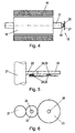
- FIG. 4 is a schematic section through an asynchronous motor with sensor.
- FIGS. 5 and 6 show schematically in two views the arrangement of two sensors on two together connected to rotation sensor wheels.
- FIG. 7 represents in supervision a hinged gate.
- FIG. 1 schematically shows the partially cutaway side view of a sliding gate.
- the drive rail 1 which is displaceable in the directions of the arrow 2 and, as shown here, on a front wheel 3 and a rear wheel 4 runs. All of these wheels are preferably a unit with or near the pedestal 6 fixed to the floor.
- the pedestal also has the drive 7, which has the motor 8, the gear 9 and an output gear 10. This output gear 10 meshes with a rack 11 which is arranged on the drive rail 1 and fixedly connected thereto.
- the drive rail is C-shaped.
- the door grille 12 On the drive rail 1, the door grille 12 is arranged, wherein the upper cross member 13 can be prevented by a holder 14 of the pedestal 6 on the side tilting.
- Denoted at 26 is a limit switch which shuts off the drive when the gate has reached the right end position and the end stop 5 formed by a pedestal.
- the rotational movement of the drive pinion 10 can also be implemented via a chain drive, belt drive or cable drive in the translational movement of the sliding or rotary movement of a swing gate or a revolving door.
- the reaction takes place without slippage, so that the rotational position of the output pinion 10 correlates with a defined displacement position of the sliding gate.
- the FIG. 2 represents in the diagram voltage vs. time the operation of the phase control. It is determined by the control between two consecutive zero voltage crossings of the angle and thus the speed. From these data, the ignition timing for the current application in the next phase is calculated. That is, when the rotor of the electric motor rotates too slowly, the phase angle is increased, and therefore, more electric power (shaded area) is supplied. If the rotor turns too fast, the phase angle is shortened and the energy supplied is reduced.
- the example illustrated schematically illustrates the situation at a desired speed of 750 revolutions / minute as the target speed.
- the measured actual speed is 770 revolutions / minute and the control gives an ignition timing of 2.5 ms after zero crossing for the next phase. It results in an excessive speed of 780 revolutions / minute, from which the control calculates the ignition time 7ms after zero crossing, so that the ignition takes place much later and within this phase, only low energy is supplied. From this follows the reduced RPM of 740 / minute, and for the next phase, the control calculates the now well-fitting time delay of 6ms after zero crossing which, under the given load conditions, reaches the target speed of 750 RPM.
- FIG. 3 the functional sequence of the speed control is shown schematically.
- the target speed is given to the control unit and the actual speed is always determined and checked, as described in more detail below. Subsequently, the setpoint speed is compared with the actual speed. If there is agreement, the phase angle is maintained. If, on the other hand, a deviation is detected, the new phase control point is calculated with a PID controller program and controlled until the setpoint speed and actual speed coincide again.
- the controller waits for the phase zero crossing and sets the timer according to the calculated ignition timing.
- the timer has expired, a triac is ignited and the motor is energized for the remainder of the phase.
- This system is not only suitable for asynchronous motors for AC or three-phase current, but also for pulse-fed DC motors. Also there, the area of the pulse can be controlled arbitrarily and therefore the energy for driving the motor can be adjusted.
- the drive control requires the determination of the actual rotational speed and, in addition, additionally prefers the determination of the respective angular position of the rotor shaft or of a drive wheel slip-free connected to the rotor shaft.
- FIG. 4 schematically shows an asynchronous motor with the stator 15, the rotor 16, the rotor shaft 17 and, on the front side of the rotor shaft 17, a sensor 18.
- This sensor 18 includes a Sensorberber 19 and a sensor receiver 20.
- Sensorberber 19 Commercially available, for example, sensor monitors based on a magnet with diametral magnetization.
- the sensor receiver comprises a microchip arranged on a circuit board 27, which scans the magnetic field of the sensor transmitter.
- Such sensors are both for determining the rotational speed U / min. as well as for counting the revolutions performed and further suitable for determining an angular position of the shaft when the shaft comes to a standstill.
- the achievable accuracy for the determination of the angular position is located at such sensors at about 1.4 °.
- the sensor 18 As in FIG. 4 is shown in order to compare the achieved actual speed of the rotor shaft 17 with the target speed can.
- This system is particularly advantageous because when starting the engine low speed and thus low speed is present, so that the controller provides the full power. Once the rated speed is reached, only the energy necessary to maintain the speed is supplied.
- the sensor 18 for speed measurement - and possibly also for counting the revolutions - must not sit directly on the shaft 17, but it can also be driven by the shaft wheels (or a wheel) may be provided, for example, a gear in the transmission, which the sensor sensor 19th wearing.
- Has a sliding door for control via the one sensor according to FIG. 4 is thus a very sensitive control of the drive on the speed of the electric motor possible.
- the gate for the positions at the respective end of travel requires conventional end stops, as denoted by the reference numeral 5 in FIG FIG. 1 is drawn.
- FIGS. 5 and 6 One solution for avoiding end stops and for always determining the state, ie the position of the load, is in the FIGS. 5 and 6 shown.
- the output shaft 21 is rotated without slipping by the electric motor 18 and may, for example, also carry the output pinion 10.
- two wheels namely a first sensor wheel 22 with a small diameter and a second sensor wheel 23 with a larger diameter, whereby the peripheral speeds the two sensor wheels are different.
- Both sensor wheels are provided on the front side with Sensorgebem, so with a first Sensorradgeber 24 and a second Sensorradgeber 25.
- Sensorgebem so with a first Sensorradgeber 24 and a second Sensorradgeber 25.
- the combination of the angular positions of the two gears is always unique and defines exactly the traveled circumferential distance of the drive pinion for the rack and therefore also the feed distance for the gate. Even after a power failure, the door position can be accurately determined based on the combination of the two angular positions of the two sensor wheels and accordingly issued a control command to move the load. End stops can be avoided.
- the sensor wheels 22, 23 may be intermeshing gears or also connected via chains or timing belt wheels.
- FIG. 7 shows a top view of a hinged door with the door leaf 30, which is pivotable about the Torangel 32 of the pedestal 33 according to arrow 31.
- the stopper post is designated 34.
- the drive 35 comprises the electric motor 8 with the rotor 16, which sets a spindle 36 in rotation via the gear 9.
- the mounted on the spindle spindle nut 37 is connected to the gate 30. Depending on the direction of rotation of the spindle 36, the opening or closing of the door occurs.
- the control according to the invention takes place in an analogous manner as in the previously described sliding door.
- the actual speed sensor of the motor is seated on the motor shaft or one of the gears.
- the sensor wheel encoders can be provided on two sensor wheels connected to each other in rotation.
Landscapes
- Power-Operated Mechanisms For Wings (AREA)
- Control Of Ac Motors In General (AREA)
- Electric Propulsion And Braking For Vehicles (AREA)
- Gates (AREA)
Abstract
Description
- Die Erfindung betrifft einen Antrieb für translatorische oder rotatorische Bewegung von Lasten wie Schiebetore, Drehtüren, Hubtoren, Schranken und dergleichen, wobei ein Elektromotor mit Wechselstrom, Drehstrom oder gepulstem Gleichstrom betrieben ist und die Drehzahl des Elektromotors (8) mittels Phasenanschnittsteuerung gesteuert ist.
- Für den elektrischen Antrieb der Bewegung der zuvor genannten Lasten ist es üblich, Asynchronmotoren zu verwenden. Beispielsweise kann ein Kurzschlussläufer mit vier Polen Verwendung finden, der mit 230 Volt bei 50 Hertz betrieben wird. Dadurch ergibt sich eine theoretische Drehzahl von 1500U/Min. In der Praxis ist durch den Schlupf die Leerlaufdrehzahl niedriger und stellt sich bei etwa 1450U/Min. ein.
- Die Drehzahlregelung von Asynchronmotoren erfolgt üblicherweise mit Frequenzsteuerung, was jedoch aufwendig und teuer ist. Eine allgemeine Aufgabe der vorliegenden Erfindung ist es, die Drehzahlregelung von Asynchronmotoren oder auch von gepulsten Gleichstrommotoren unter Vermeidung einer Frequenzsteuerung vorzunehmen, ohne dabei die Vorteile einer elektronischen Drehzahlregelung einzubüßen.
- Aus dem Stand der Technik ist bekannt, für den Zweck der Drehzahlregelung des Elektromotors eine Phasenanschnittsteuerung vorzusehen.
Demnach ist die vorliegende Erfindung dadurch gekennzeichnet, dass die Drehzahl des Elektromotors mittels Phasenanschnittsteuerung gesteuert ist. - Ein weiteres Problem tritt bei Lasten, die in definierter Weise bewegt werden sollen, dadurch auf, dass die Antriebssteuerung selbst erkennen soll, in welcher Stellung sich die Last befindet. Beispielsweise verfügen Schiebetore über Abstellmechanismen, die durch Sensoren wie Laserschranken oder Berührungssensoren den Antrieb des Tores unterbrechen. Bisher war es üblich, in den jeweiligen Endstellungen Endanschläge und/ oder Endschalter vorzusehen, die zum Einen den Antrieb abstellen, wenn das Tor die Endstellung erreicht hat und die zum Anderen als Nullpunkt für den Antrieb dienen, wenn der Antrieb während der Bewegung der Last unterbrochen wurde. Derartige Endanschläge und Endschalter verteuern die Torkonstruktion und sind überdies störungsanfällig, da sie den Witterungseinflüssen und mechanischen Einflüssen unterworfen sind.
- Aufgabe der vorliegenden Erfindung ist es somit auch, den Antrieb so auszugestalten, dass die Antriebssteuerung jederzeit die Stellung der bewegten Last erkennt und Endanschläge und Endschalter überflüssig werden. Bei einer Unterbrechung der Bewegung der Last soll die Position innerhalb des vorgesehenen Bewegungsbereiches ermittelbar sein, sodass danach die Bewegung der Last zu einem der Endpunkte wieder durchführbar ist.
- Was im folgenden anhand eines Schiebetores beschrieben wird, gilt gleicherweise für translatorische und auch rotatorische Bewegungen wie z.B. von Drehtüren, Hubtoren und Schranken. Derartige Absperrungen dienen zur Sperre und Freigabe von Fahrwegen, Garagen, Einfahrten zu Betriebsgeländen etc.
- Die Erfindung ist dadurch gekennzeichnet, dass ein, die Ist-Drehzahl und die Drehstellung des Rotors des Elektromotors oder eines mit diesem auf Drehung verbundenen Sensorrades messender, Sensor vorgesehen ist.
- Nach einem weiteren Merkmal der Erfindung weist der Sensor einen direkt auf der Welle des Rotors angeordneten Sensorgeber und einen ortsfesten Sensorempfänger auf. Die Messtoleranz der Winkelstellung des Sensors ist bevorzugt <15° besonders bevorzugt <5°. Die Steuerung kann in vorteilhafter Weise einen Zähler zum Zählen der Umdrehungen der mit dem Sensor verbundenen Welle oder eines Sensorrades aufweisen, wobei als Nullpunkt eine vorgegebene Endstellung der vom Antrieb bewegten Last festgelegt ist. Gemäß einer weiteren Ausbildung der Erfindung kann zur Positionsermittlung der Last ein erstes Sensorrad und ein zweites auf Drehung verbundenes Sensorrad vorgesehen sein, die mit der Rotorwelle oder einer Abtriebswelle in schlupfloser Drehverbindung stehen, wobei das erste und zweite Sensorrad voneinander unterschiedliche Durchmesser haben und beide mit Sensorradgeber versehen sind, denen Sensorradempfänger zugeordnet sind.
- Weitere vorteilhafte Merkmale sind den Ansprüchen, der nachfolgenden Beschreibung und den Zeichnungen zu entnehmen.
- Im folgenden wird die Erfindung anhand eines Ausführungsbeispieles näher erläutert.
- Hinsichtlich der Steuerung und Stromversorgung umfasst dieses Ausführungsbeispiel einen Asynchronmotor für 230 Volt bei 50 Hertz mit einer Nenndrehzahl von 1.500 U/Min. Das erste Anwendungsbeispiel bezieht sich auf ein motorbetriebenes Schiebetor. Ein weiteres Beispiel beschreibt ein Drehtor.
-
Figur 1 zeigt schematisch erfindungswesentliche Teile eines Schiebetors.Figur 2 erläutert die Funktionsweise der Phasenanschnittsteuerung eines Asynchronmotors gemäß Erfindung;Figur 3 ist das Schema für den Programmablauf der Antriebssteuerung.Figur 4 ist ein schematischer Schnitt durch einen Asynchronmotor mit Sensor.Figur 5 und 6 zeigen schematisch in zwei Ansichten die Anordnung von zwei Sensoren auf zwei miteinander auf Drehung verbundenen Sensorrädern.Figur 7 stellt in Aufsicht ein Drehtor dar. -
Figur 1 zeigt schematisch die teilweise aufgeschnittene Seitenansicht eines Schiebetors. Als tragendes Element dient die Laufwerksschiene 1, die in die Richtungen des Pfeiles 2 verschiebbar ist und, wie hier dargestellt, auf einem vorderen Laufrad 3 und einem hinteren Laufrad 4 läuft. Alle diese Laufräder sind bevorzugt eine Einheit mit oder nahe der am Boden befestigten Standsäule 6. Die Standsäule weist weiters den Antrieb 7 auf, der den Motor 8, das Getriebe 9 und ein Abtriebsritzel 10 aufweist. Dieses Abtriebsritzel 10 kämmt mit einer Zahnstange 11, die an der Laufwerksschiene 1 angeordnet und mit dieser fest verbunden ist. Üblicherweise ist die Laufwerksschiene C-förmig. - Auf der Laufwerksschiene 1 ist das Torgitter 12 angeordnet, wobei die obere Querstrebe 13 von einer Halterung 14 der Standsäule 6 am seitlichen Kippen gehindert werden kann. Mit 26 ist ein Endschalter bezeichnet, der den Antrieb abschaltet, wenn das Tor die rechte Endlage und den durch eine Standsäule gebildeten Endanschlag 5 erreicht hat.
- Die geschilderte Konstruktion ist nur rein schematisch gehalten und beschrieben. Derartige Torkonstruktionen sind in vielfältiger Weise wandelbar und es existieren viele derartige Konstruktionen in der Praxis. So kann die Drehbewegung des Antriebsritzels 10 auch über einen Kettentrieb, Riementrieb oder Seiltrieb in die translatorische Bewegung des Schiebtors oder Drehbewegung eines Drehtors oder einer Drehtür umgesetzt werden. Für die exakte Funktion ist es vorteilhaft, wenn die Umsetzung ohne Schlupf erfolgt, sodass die Drehstellung des Abtriebsritzels 10 mit einer definierten Verschiebelage des Schiebetores korreliert. Selbstverständlich soll auch die Drehbewegung des Abtriebsritzels 10 mit der Drehung der Rotorwelle des Motors 8 korrelieren.
- Die
Figur 2 stellt im Diagramm Spannung gegen Zeit die Funktionsweise der Phasenanschnittsteuerung dar. Es wird vom Steuerelement zwischen zwei aufeinanderfolgenden Spannungsnulldurchgängen der Winkel und damit die Drehzahl ermittelt. Aus diesen Daten wird der Zündzeitpunkt für die Strombeaufschlagung in der nächsten Phase errechnet. Das heißt, wenn sich der Rotor des Elektromotors zu langsam dreht, wird der Phasenanschnitt erhöht und daher wird mehr elektrische Energie (schraffierter Bereich) zugeführt. Dreht der Rotor zu schnell, wird der Phasenanschnitt verkürzt und die zugeführte Energie wird reduziert. - Das dargestellte Beispiel veranschaulicht schematisch die Situation bei einer gewünschten Drehzahl von 750 Umdrehungen/Minute als Soll-Drehzahl. In der ersten Phase beträgt die gemessene Ist-Drehzahl 770 Umdrehungen/Minute und das Steuerelement gibt einen Zündzeitpunkt von 2,5 ms nach Nulldurchgang für die nächste Phase vor. Es ergibt sich eine zu hohe Drehzahl von 780 Umdrehungen/Minute, woraus das Steuerelement den Zündzeitpunkt 7ms nach Nulldurchgang berechnet, sodass die Zündung wesentlich später erfolgt und innerhalb dieser Phase nur mehr geringe Energie zugeführt wird. Daraus folgt die verringerte Umdrehungszahl von 740/Minute und für die nächste Phase berechnet das Steuerelement die jetzt gut passende Zeitverzögerung von 6ms nach Nulldurchgang, wodurch unter den gegebenen Belastungszuständen die Soll-Drehzahl von 750 Umdrehungen/Minute erreicht ist.
- Gemäß
Figur 3 ist der Funktionsablauf der Drehzahlregelung schematisch wiedergegeben. - Die Soll-Drehzahl ist dem Steuergerät vorgegeben und die Ist-Drehzahl wird stets ermittelt und überprüft, wie nachstehend näher beschrieben ist. In weiterer Folge wird die Soll-Drehzahl mit der Ist-Drehzahl verglichen. Wenn Übereinstimmung gegeben ist, wird der Phasenanschnitt beibehalten. Wird hingegen eine Abweichung festgestellt, wird mit einem PID-Reglerprogramm der neue Phasenanschnittpunkt berechnet und solange geregelt, bis wieder die Soll-Drehzahl und Ist-Drehzahl übereinstimmen.
- Wenn der Phasenanschnitt definiert ist, wartet die Steuerung auf den Phasen-Nulldurchgang und setzt den Zeitgeber gemäß berechnetem Zündzeitpunkt. Wenn der Zeitgeber abgelaufen ist, wird ein Triac gezündet und der Motor über den Rest der Phase mit Energie beaufschlagt.
- Dieses System ist nicht nur für Asynchronmotoren für Wechselstrom- oder Drehstrom geeignet, sondern auch für pulsgespeiste Gleichstrommotoren. Auch dort kann die Fläche des Pulses beliebig gesteuert und daher die Energie für den Antrieb des Motors eingestellt werden.
- Wie zuvor beschrieben, benötigt die Antriebssteuerung die Ermittlung der Ist-Drehzahl und bevorzugt zusätzlich auch noch die Ermittlung der jeweiligen Winkelstellung der Rotorwelle oder eines mit der Rotorwelle schlupflos verbundenen Treibrades.
-
Figur 4 zeigt schematisch einen Asynchronmotor mit dem Stator 15, dem Rotor 16, der Rotorwelle 17 und, an der Stirnseite der Rotorwelle 17 einen Sensor 18. Dieser Sensor 18 umfasst einen Sensorgeber 19 und einen Sensorempfänger 20. Im Handel erhältlich sind beispielsweise Sensorgeber auf Basis eines Magnet mit diametraler Magnetisierung. Der Sensorempfänger umfasst einen auf einer Platine 27 angeordneten Mikrochip, der das Magnetfeld des Sensorgebers abtastet. Derartige Sensoren sind sowohl zur Ermittlung der Umdrehungsgeschwindigkeit U/Min. als auch zum Zählen der durchgeführten Umdrehungen und weiters auch zur Ermittlung einer Winkelstellung der Welle geeignet, wenn die Welle zum Stillstand kommt. Die erreichbare Genauigkeit für die Ermittlung der Winkelstellung ist bei solchen Sensoren etwa bei 1,4° gelegen. - Selbstverständlich sind auch Sensoren anderer Bauart einsetzbar wie z.B. solche, die mit Laserlicht arbeiten. Grundsätzlich sind alle Sensorsysteme geeignet, die die gewünschten Daten liefern.
- Für die in den
Figuren 2 und3 dargestellte Antriebstechnik dient der Sensor 18, wie er inFigur 4 dargestellt ist, um die erreichte Ist-Drehzahl der Rotorwelle 17 mit der Soll-Drehzahl vergleichen zu können. Dieses System ist insbesondere dadurch günstig, als beim Anfahren des Motors eine geringe Geschwindigkeit und damit geringe Drehzahl vorhanden ist, sodass die Steuerung die volle Energie zur Verfügung stellt. Sobald die Nenndrehzahl erreicht ist, wird nur die zum Aufrechterhalten der Geschwindigkeit notwendige Energie zugeführt. Der Sensor 18 zur Drehzahlmessung - und gegebenenfalls auch zur Zählung der Umdrehungen - muss nicht an der Welle 17 direkt sitzen, sondern es können auch von der Welle angetriebene Räder (oder ein Rad) vorgesehen sein, z.B. ein Zahnrad im Getriebe, welches den Sensorgeber 19 trägt. - Verfügt ein Schiebetor zur Steuerung über den einen Sensor gemäß
Figur 4 , ist damit eine sehr feinfühlige Steuerung des Antriebes über die Drehzahl des Elektromotors möglich. Allerdings benötigt das Tor für die Stellungen am jeweiligen Bewegungsende herkömmliche Endanschläge, wie er mit dem Bezugszeichen 5 inFigur 1 eingezeichnet ist. - Zwar ist es möglich, anhand der gezählten Umdrehungen der Rotorwelle oder des Abtriebsritzels die zurückgelegte Strecke der Last zu berechnen. Bei Stromausfall würde diese Information jedoch verloren gehen und die Nullstellung der Last und der Steuervorrichtung müsste per Hand eingestellt werden.
- Eine Lösung für das Vermeiden von Endanschlägen und für das jederzeitige Ermitteln des Standes, also der Position der Last, ist in den
Figuren 5 und 6 dargestellt. - Die Abtriebswelle 21 ist vom Elektromotor 18 schlupflos gedreht und kann beispielsweise auch das Abtriebsritzel 10 tragen. Damit auf schlupflose Drehung verbunden sind zwei Räder, nämlich ein erstes Sensorrad 22 mit kleinem Durchmesser und ein zweites Sensorrad 23 mit größerem Durchmesser, wodurch die Umfangsgeschwindigkeiten der beiden Sensorräder verschieden sind. Beide Sensorräder sind stirnseitig mit Sensorgebem versehen, also mit einem ersten Sensorradgeber 24 und einem zweiten Sensorradgeber 25. Diese arbeiten mit dem ersten Sensorradempfänger 28 und dem zweiten Sensorradempfänger 29 zusammen. Diese Sensoren sind geeignet, die Winkelstellung jedes Zahnrades mit der notwendigen Genauigkeit zu messen. Wie zuvor beschrieben ist handelsüblich eine Genauigkeit von 1,4° erreichbar und ausreichend. Die Kombination der Winkelstellungen der beiden Zahnräder ist immer einmalig und definiert exakt die zurückgelegte Umfangsstrecke des Antriebsritzels für die Zahnstange und daher auch die Vorschubstrecke für das Tor. Selbst nach einem Stromausfall kann so anhand der Kombination der beiden Winkelstellungen der beiden Sensorräder die Torposition genau ermittelt und dementsprechend ein Steuerbefehl zum Bewegen der Last erteilt werden. Endanschläge können damit vermieden werden.
- Alle diese Räder und Sensorräder können mit dem Antrieb 7 als Baueinheit ausgeführt werden. Die Sensorräder 22, 23 können miteinander kämmende Zahnräder oder auch über Ketten oder Zahnriemen verbundene Räder sein.
- Die
Figur 7 zeigt in Aufsicht von oben ein Drehtor mit dem Torflügel 30, der gemäß Pfeil 31 um die Torangel 32 der Standsäule 33 schwenkbar ist. Der Anschlagpfosten ist mit 34 bezeichnet. - Der Antrieb 35 umfasst den Elektromotor 8 mit dem Rotor 16, der über das Getriebe 9 eine Spindel 36 in Drehung versetzt. Die auf der Spindel aufgesetzte Spindelmutter 37 ist mit dem Torflügel 30 verbunden. Je nach Drehrichtung der Spindel 36 erfolgt das Öffnen oder Schließen des Tores.
- Die erfindungsgemäße Steuerung erfolgt auf analoge Weise wie beim zuvor beschriebenen Schiebetor. Der Sensor für die Ist-Drehzahl des Motors sitzt an der Motorwelle oder einer der Getrieberäder. Ebenfalls können auf zwei miteinander auf Drehung verbundenen Sensorrädem die Sensorradgeber vorgesehen sein.
-
- 1.
- Laufwerksschiene
- 2.
- Pfeil
- 3.
- vorderes Laufrad
- 4.
- hinteres Laufrad
- 5.
- Endanschlag
- 6.
- Standsäule
- 7.
- Antrieb
- 8.
- Motor
- 9.
- Getriebe
- 10.
- Abtriebsritzel
- 11.
- Zahnstage
- 12.
- Torgitter
- 13.
- obere Querstrebe
- 14.
- Halterung
- 15.
- Stator
- 16.
- Rotor
- 17.
- Rotorwelle
- 18.
- Sensor
- 19.
- Sensorgeber
- 20.
- Sensorempfänger
- 21.
- Abtriebswelle
- 22.
- erstes Sensorrad
- 23.
- zweites Sensorrad
- 24.
- erster Sensorradgeber
- 25.
- zweiter Sensorradgeber
- 26.
- Endschalter
- 27.
- Platine
- 28.
- Erster Sensorradempfänger
- 29.
- Zweiter Sensorradempfänger
- 30.
- Torflügel
- 31.
- Pfeil
- 32.
- Torangel
- 33.
- Standsäule
- 34.
- Anschlagpfosten
- 35.
- Antrieb
- 36.
- Spindel
- 37.
- Spindelmutter
Claims (12)
- Antrieb für translatorische oder rotatorische Bewegung von Lasten wie Schiebetore, Drehtüren und Drehtore, Hubtore, Schranken, insbesondere zur Sperre und Freigabe von Fahrwegen und Garagen etc., wobei ein Elektromotor (8) mit Wechselstrom, Drehstrom, oder gepulstem Gleichstrom betrieben ist und die Drehzahl des Elektromotors (8) mittels Phasenanschnittsteuerung gesteuert ist, dadurch gekennzeichnet, dass ein, die Ist-Drehzahl und gegebenenfalls auch die Drehstellung des Rotors (16) oder der Rotorwelle (17) des Elektromotors (8) oder eines mit diesem drehverbundenen Sensorrades messender, Sensor (18) vorgesehen ist.
- Antrieb nach Anspruch 1, dadurch gekennzeichnet, dass zur Steuerung des Elektromotors (8) ein Steuerelement zum Vergleich der Ist-Drehzahl mit einer vorgegebenen Soll-Drehzahl und zur Berechnung des erforderlichen Phasenanschnittpunktes vorgesehen ist.
- Antrieb nach Anspruch 1 oder 2, dadurch gekennzeichnet, dass der Sensor (18) einen direkt auf der Welle (17) des Rotors (16) angeordneten Sensorgeber (19) und einen ortsfesten Sensorempfänger (20) aufweist.
- Antrieb nach einem der Ansprüche 1 bis 3, dadurch gekennzeichnet, dass die Meßtoleranz der Winkelstellung des Sensors (18) kleiner 15°, bevorzugt kleiner 5° ist.
- Antrieb nach einem der Ansprüche 1 bis 4, dadurch gekennzeichnet, dass ein Zähler zum Zählen der Umdrehungen der mit dem Sensor (18) verbundenen Rotorwelle (17) oder eines damit verbundenen Sensorrades vorgesehen ist, wobei als Nullpunkt eine vorgegebene Endstellung der vom Antrieb bewegten Last festgelegt ist.
- Antrieb nach einem der Ansprüche 1 bis 5, dadurch gekennzeichnet, dass zur Positionsermittlung der Last ein erstes Sensorrad (22) und ein auf Drehung verbundenes zweites Sensorrad (23) vorgesehen sind, die mit der Rotorwelle (17) oder mit einer, mit der Rotorwelle (17) verbundenen, Abtriebswelle (21) in schlupfloser Drehverbindung stehen, wobei das erste Sensorrad (22) und das zweite Sensorrad (23) voreinander unterschiedliche Durchmesser haben und beide mit Sensorradgebern (24, 25) versehen sind, denen Sensorradempfänger (28, 29) zugeordnet sind.
- Antrieb nach einem der Ansprüche 1 bis 6, dadurch gekennzeichnet, dass die Sensorräder (23, 24) miteinander kämmende Zahnräder oder über Ketten oder Zahnriemen verbundene Räder sind.
- Antrieb nach einem der Ansprüche 1 bis 7, dadurch gekennzeichnet, dass der zur Drehzahlregelung des Motors vorgesehene Sensor (18) auf einem mit der Rotorwelle (17) auf Drehung verbundenen Sensorrad angeordnet ist.
- Antrieb nach einem der Ansprüche 1 bis 8, dadurch gekennzeichnet, dass zur Umsetzung der Drehbewegung des Abtriebsritzels (10) ein Zahnstangentrieb, Kettentrieb, Seiltrieb oder Spindeltrieb vorgesehen ist.
- Antrieb nach einem der Ansprüche 3 bis 9, dadurch gekennzeichnet, dass der Sensorgeber (19) einen Magnet mit diametraler Magnetisierung aufweist, und der Sensorempfänger (20) einen, das Magnetfeld des Sensorgebers (19) abtastenden, Mikrochip umfasst.
- Antrieb nach einem der Ansprüche 1 bis 10, dadurch gekennzeichnet, dass der Sensor (18) nicht direkt am Rotor (16) oder an der Rotorwelle (17) befestigt ist, sondern mit diesem über ein oder mehrere angetriebene Räder, einsbesondere ein Zahnrad oder ein Getriebe, verbunden ist.
- Antrieb nach einem der Ansprüche 6 bis 11, dadurch gekennzeichnet, dass die Durchmesser der Sensorräder (22) und (23) derart gewählt sind, dass die Kombination der Winkelstellungen stets einmalig ist und exakt die zurückgelegte Vorschubstrecke des Tors kennzeichnet.
Priority Applications (1)
| Application Number | Priority Date | Filing Date | Title |
|---|---|---|---|
| PL10000759T PL2213822T3 (pl) | 2009-01-29 | 2010-01-26 | Napęd dla ruchu postępowego lub obrotowego ciężarów |
Applications Claiming Priority (1)
| Application Number | Priority Date | Filing Date | Title |
|---|---|---|---|
| AT0015709A AT509176B1 (de) | 2009-01-29 | 2009-01-29 | Antrieb für translatorische oder rotatorische bewegung von lasten |
Publications (3)
| Publication Number | Publication Date |
|---|---|
| EP2213822A2 true EP2213822A2 (de) | 2010-08-04 |
| EP2213822A3 EP2213822A3 (de) | 2014-06-18 |
| EP2213822B1 EP2213822B1 (de) | 2018-12-19 |
Family
ID=42173381
Family Applications (1)
| Application Number | Title | Priority Date | Filing Date |
|---|---|---|---|
| EP10000759.0A Active EP2213822B1 (de) | 2009-01-29 | 2010-01-26 | Antrieb für translatorische oder rotatorische Bewegung von Lasten |
Country Status (5)
| Country | Link |
|---|---|
| EP (1) | EP2213822B1 (de) |
| AT (1) | AT509176B1 (de) |
| ES (1) | ES2714677T3 (de) |
| PL (1) | PL2213822T3 (de) |
| TR (1) | TR201902101T4 (de) |
Family Cites Families (5)
| Publication number | Priority date | Publication date | Assignee | Title |
|---|---|---|---|---|
| DE2405281A1 (de) * | 1974-02-04 | 1975-08-21 | Ver Baubeschlag Gretsch Co | Antrieb fuer automatische tueroeffnungsanlagen |
| CH608558A5 (en) * | 1976-11-04 | 1979-01-15 | Hansruedi Zuest | Electronically controlled drive and control circuit for automatic operation of a door |
| JPS5826178A (ja) * | 1981-08-11 | 1983-02-16 | 北陽電機株式会社 | 自動扉開閉装置 |
| US4831509A (en) * | 1986-04-16 | 1989-05-16 | Byrne & Davidson Doors (N.S.W.)Pty. Limited | Door operation control apparatus |
| DE202007005749U1 (de) * | 2006-07-10 | 2007-11-22 | BROSE SCHLIEßSYSTEME GMBH & CO. KG | Positionserfassungsanordnung für ein motorisch verstellbares Funktionselement in einem Kraftfahrzeug |
-
2009
- 2009-01-29 AT AT0015709A patent/AT509176B1/de active
-
2010
- 2010-01-26 EP EP10000759.0A patent/EP2213822B1/de active Active
- 2010-01-26 ES ES10000759T patent/ES2714677T3/es active Active
- 2010-01-26 TR TR2019/02101T patent/TR201902101T4/tr unknown
- 2010-01-26 PL PL10000759T patent/PL2213822T3/pl unknown
Non-Patent Citations (1)
| Title |
|---|
| None |
Also Published As
| Publication number | Publication date |
|---|---|
| EP2213822A3 (de) | 2014-06-18 |
| EP2213822B1 (de) | 2018-12-19 |
| AT509176A1 (de) | 2011-06-15 |
| AT509176B1 (de) | 2011-12-15 |
| PL2213822T3 (pl) | 2019-07-31 |
| TR201902101T4 (tr) | 2019-03-21 |
| ES2714677T3 (es) | 2019-05-29 |
Similar Documents
| Publication | Publication Date | Title |
|---|---|---|
| EP1894877B1 (de) | Türantrieb für eine automatische Tür | |
| DE102005039532B4 (de) | Antriebseinheit für eine Tür oder ein Tor, insbesondere für ein Garagentor und Verfahren zum Betrieb einer solchen Antriebseinheit für eine Tür oder ein Tor, insbesondere für ein Garagentor | |
| EP1934424B1 (de) | Vorrichtung und verfahren zum verschliessen oder zum öffnen und schliessen von wenigstens einer schublade, klappe | |
| WO2013029751A1 (de) | Verfahren und vorrichtung zur überwachung eines einen rotierenden antriebsmotor aufweisenden antriebsaggregats, insbesondere eines fensterhebers | |
| DE4138194C2 (de) | Verfahren und Vorrichtung zur Erfassung der Position und Bewegungsrichtung translatorisch und/oder rotatorisch bewegter Aggregate | |
| EP1902995B1 (de) | Türantrieb für eine automatische Tür | |
| DE102014210069A1 (de) | Sensorlose BEMF-Messung für stromgeregelte bürstenlose Motoren | |
| DE4339565C2 (de) | Verfahren und Vorrichtung zur Steuerung eines motorisch betriebenen Torblattes | |
| DE102006062333A1 (de) | Türantrieb | |
| DE69607058T2 (de) | Elektronisches Steuerungsverfahren zum Öffnen und/oder Schliessen einer Tür und Gerät dafür | |
| EP2213822B1 (de) | Antrieb für translatorische oder rotatorische Bewegung von Lasten | |
| EP3555572B1 (de) | Verfahren und vorrichtung zum bestimmen einer position eines stellelements | |
| DE102011107867B4 (de) | Verfahren zum Betrieb eines Gebäudeverschlusses | |
| DE102011001884B3 (de) | Verfahren zum Steuern eines Türantriebs | |
| EP1149451B1 (de) | Verfahren und steuerung zum steuern einer antriebsvorrichtung für eine abschlusseinrichtung eines gebäudes oder einer einfriedung | |
| EP0650107A1 (de) | Steuersystem für motorische Antriebe | |
| EP1087279B1 (de) | Verfahren zur automatischen Bestimmung der Auftreffgeschwindigkeit einer Aufzugtür auf einem Hindernis | |
| EP0770329B1 (de) | System für Walzspalteinstellung | |
| EP1160409A2 (de) | Falttürantrieb | |
| DE19919200A1 (de) | Verfahren zur Endlagenbestimmung von Toren sowie Torantrieb zur Durchführung des Verfahrens | |
| DE19636267C2 (de) | Verfahren zum Stillsetzen eines auf einer Hauptwelle einer Auswuchtmaschine aufgespannten und von einem Elektromotor angetriebenen Rotors | |
| DE102012210592C5 (de) | Automatische Drehtüranlage sowie Verfahren zum Betrieb einer automatischen Drehtüranlage | |
| DE102007044645B4 (de) | Vorrichtung zur Erfassung einer Rotationsgröße sowie Verfahren zur Auswertung eines Sensorausgangssignals | |
| DE19953265B4 (de) | Verfahren zum Anfahren eines Gleichstrommotors | |
| DE19619971A1 (de) | Schiebedachsteuerung mit inkrementeller Positionsbestimmung mit dynamischer Nullstellung |
Legal Events
| Date | Code | Title | Description |
|---|---|---|---|
| PUAI | Public reference made under article 153(3) epc to a published international application that has entered the european phase |
Free format text: ORIGINAL CODE: 0009012 |
|
| AK | Designated contracting states |
Kind code of ref document: A2 Designated state(s): AT BE BG CH CY CZ DE DK EE ES FI FR GB GR HR HU IE IS IT LI LT LU LV MC MK MT NL NO PL PT RO SE SI SK SM TR |
|
| AX | Request for extension of the european patent |
Extension state: AL BA RS |
|
| PUAL | Search report despatched |
Free format text: ORIGINAL CODE: 0009013 |
|
| AK | Designated contracting states |
Kind code of ref document: A3 Designated state(s): AT BE BG CH CY CZ DE DK EE ES FI FR GB GR HR HU IE IS IT LI LT LU LV MC MK MT NL NO PL PT RO SE SI SK SM TR |
|
| AX | Request for extension of the european patent |
Extension state: AL BA RS |
|
| RIC1 | Information provided on ipc code assigned before grant |
Ipc: E05F 15/00 20060101AFI20140513BHEP Ipc: H02H 7/085 20060101ALI20140513BHEP |
|
| 17P | Request for examination filed |
Effective date: 20141008 |
|
| RBV | Designated contracting states (corrected) |
Designated state(s): AT BE BG CH CY CZ DE DK EE ES FI FR GB GR HR HU IE IS IT LI LT LU LV MC MK MT NL NO PL PT RO SE SI SK SM TR |
|
| STAA | Information on the status of an ep patent application or granted ep patent |
Free format text: STATUS: EXAMINATION IS IN PROGRESS |
|
| 17Q | First examination report despatched |
Effective date: 20170228 |
|
| REG | Reference to a national code |
Ref country code: DE Ref legal event code: R079 Ref document number: 502010015632 Country of ref document: DE Free format text: PREVIOUS MAIN CLASS: E05F0015000000 Ipc: H02H0007085000 |
|
| RIC1 | Information provided on ipc code assigned before grant |
Ipc: H02H 7/085 20060101AFI20180523BHEP Ipc: E05F 15/40 20150101ALI20180523BHEP Ipc: E05F 15/00 20060101ALI20180523BHEP |
|
| GRAP | Despatch of communication of intention to grant a patent |
Free format text: ORIGINAL CODE: EPIDOSNIGR1 |
|
| STAA | Information on the status of an ep patent application or granted ep patent |
Free format text: STATUS: GRANT OF PATENT IS INTENDED |
|
| INTG | Intention to grant announced |
Effective date: 20180718 |
|
| GRAS | Grant fee paid |
Free format text: ORIGINAL CODE: EPIDOSNIGR3 |
|
| GRAA | (expected) grant |
Free format text: ORIGINAL CODE: 0009210 |
|
| STAA | Information on the status of an ep patent application or granted ep patent |
Free format text: STATUS: THE PATENT HAS BEEN GRANTED |
|
| AK | Designated contracting states |
Kind code of ref document: B1 Designated state(s): AT BE BG CH CY CZ DE DK EE ES FI FR GB GR HR HU IE IS IT LI LT LU LV MC MK MT NL NO PL PT RO SE SI SK SM TR |
|
| REG | Reference to a national code |
Ref country code: GB Ref legal event code: FG4D Free format text: NOT ENGLISH |
|
| REG | Reference to a national code |
Ref country code: CH Ref legal event code: EP |
|
| REG | Reference to a national code |
Ref country code: DE Ref legal event code: R096 Ref document number: 502010015632 Country of ref document: DE |
|
| REG | Reference to a national code |
Ref country code: IE Ref legal event code: FG4D Free format text: LANGUAGE OF EP DOCUMENT: GERMAN |
|
| REG | Reference to a national code |
Ref country code: AT Ref legal event code: REF Ref document number: 1079713 Country of ref document: AT Kind code of ref document: T Effective date: 20190115 |
|
| REG | Reference to a national code |
Ref country code: CH Ref legal event code: NV Representative=s name: TROESCH SCHEIDEGGER WERNER AG, CH |
|
| REG | Reference to a national code |
Ref country code: SE Ref legal event code: TRGR |
|
| REG | Reference to a national code |
Ref country code: NL Ref legal event code: FP |
|
| PG25 | Lapsed in a contracting state [announced via postgrant information from national office to epo] |
Ref country code: LV Free format text: LAPSE BECAUSE OF FAILURE TO SUBMIT A TRANSLATION OF THE DESCRIPTION OR TO PAY THE FEE WITHIN THE PRESCRIBED TIME-LIMIT Effective date: 20181219 Ref country code: HR Free format text: LAPSE BECAUSE OF FAILURE TO SUBMIT A TRANSLATION OF THE DESCRIPTION OR TO PAY THE FEE WITHIN THE PRESCRIBED TIME-LIMIT Effective date: 20181219 Ref country code: LT Free format text: LAPSE BECAUSE OF FAILURE TO SUBMIT A TRANSLATION OF THE DESCRIPTION OR TO PAY THE FEE WITHIN THE PRESCRIBED TIME-LIMIT Effective date: 20181219 Ref country code: BG Free format text: LAPSE BECAUSE OF FAILURE TO SUBMIT A TRANSLATION OF THE DESCRIPTION OR TO PAY THE FEE WITHIN THE PRESCRIBED TIME-LIMIT Effective date: 20190319 Ref country code: FI Free format text: LAPSE BECAUSE OF FAILURE TO SUBMIT A TRANSLATION OF THE DESCRIPTION OR TO PAY THE FEE WITHIN THE PRESCRIBED TIME-LIMIT Effective date: 20181219 Ref country code: NO Free format text: LAPSE BECAUSE OF FAILURE TO SUBMIT A TRANSLATION OF THE DESCRIPTION OR TO PAY THE FEE WITHIN THE PRESCRIBED TIME-LIMIT Effective date: 20190319 |
|
| REG | Reference to a national code |
Ref country code: LT Ref legal event code: MG4D |
|
| REG | Reference to a national code |
Ref country code: ES Ref legal event code: FG2A Ref document number: 2714677 Country of ref document: ES Kind code of ref document: T3 Effective date: 20190529 |
|
| PG25 | Lapsed in a contracting state [announced via postgrant information from national office to epo] |
Ref country code: GR Free format text: LAPSE BECAUSE OF FAILURE TO SUBMIT A TRANSLATION OF THE DESCRIPTION OR TO PAY THE FEE WITHIN THE PRESCRIBED TIME-LIMIT Effective date: 20190320 |
|
| PG25 | Lapsed in a contracting state [announced via postgrant information from national office to epo] |
Ref country code: PT Free format text: LAPSE BECAUSE OF FAILURE TO SUBMIT A TRANSLATION OF THE DESCRIPTION OR TO PAY THE FEE WITHIN THE PRESCRIBED TIME-LIMIT Effective date: 20190419 |
|
| PG25 | Lapsed in a contracting state [announced via postgrant information from national office to epo] |
Ref country code: RO Free format text: LAPSE BECAUSE OF FAILURE TO SUBMIT A TRANSLATION OF THE DESCRIPTION OR TO PAY THE FEE WITHIN THE PRESCRIBED TIME-LIMIT Effective date: 20181219 Ref country code: SK Free format text: LAPSE BECAUSE OF FAILURE TO SUBMIT A TRANSLATION OF THE DESCRIPTION OR TO PAY THE FEE WITHIN THE PRESCRIBED TIME-LIMIT Effective date: 20181219 Ref country code: IS Free format text: LAPSE BECAUSE OF FAILURE TO SUBMIT A TRANSLATION OF THE DESCRIPTION OR TO PAY THE FEE WITHIN THE PRESCRIBED TIME-LIMIT Effective date: 20190419 Ref country code: SM Free format text: LAPSE BECAUSE OF FAILURE TO SUBMIT A TRANSLATION OF THE DESCRIPTION OR TO PAY THE FEE WITHIN THE PRESCRIBED TIME-LIMIT Effective date: 20181219 Ref country code: EE Free format text: LAPSE BECAUSE OF FAILURE TO SUBMIT A TRANSLATION OF THE DESCRIPTION OR TO PAY THE FEE WITHIN THE PRESCRIBED TIME-LIMIT Effective date: 20181219 |
|
| REG | Reference to a national code |
Ref country code: DE Ref legal event code: R097 Ref document number: 502010015632 Country of ref document: DE |
|
| PG25 | Lapsed in a contracting state [announced via postgrant information from national office to epo] |
Ref country code: LU Free format text: LAPSE BECAUSE OF NON-PAYMENT OF DUE FEES Effective date: 20190126 |
|
| PLBE | No opposition filed within time limit |
Free format text: ORIGINAL CODE: 0009261 |
|
| STAA | Information on the status of an ep patent application or granted ep patent |
Free format text: STATUS: NO OPPOSITION FILED WITHIN TIME LIMIT |
|
| PG25 | Lapsed in a contracting state [announced via postgrant information from national office to epo] |
Ref country code: DK Free format text: LAPSE BECAUSE OF FAILURE TO SUBMIT A TRANSLATION OF THE DESCRIPTION OR TO PAY THE FEE WITHIN THE PRESCRIBED TIME-LIMIT Effective date: 20181219 Ref country code: MC Free format text: LAPSE BECAUSE OF FAILURE TO SUBMIT A TRANSLATION OF THE DESCRIPTION OR TO PAY THE FEE WITHIN THE PRESCRIBED TIME-LIMIT Effective date: 20181219 |
|
| 26N | No opposition filed |
Effective date: 20190920 |
|
| PG25 | Lapsed in a contracting state [announced via postgrant information from national office to epo] |
Ref country code: SI Free format text: LAPSE BECAUSE OF FAILURE TO SUBMIT A TRANSLATION OF THE DESCRIPTION OR TO PAY THE FEE WITHIN THE PRESCRIBED TIME-LIMIT Effective date: 20181219 |
|
| PG25 | Lapsed in a contracting state [announced via postgrant information from national office to epo] |
Ref country code: MT Free format text: LAPSE BECAUSE OF FAILURE TO SUBMIT A TRANSLATION OF THE DESCRIPTION OR TO PAY THE FEE WITHIN THE PRESCRIBED TIME-LIMIT Effective date: 20181219 |
|
| PG25 | Lapsed in a contracting state [announced via postgrant information from national office to epo] |
Ref country code: CY Free format text: LAPSE BECAUSE OF FAILURE TO SUBMIT A TRANSLATION OF THE DESCRIPTION OR TO PAY THE FEE WITHIN THE PRESCRIBED TIME-LIMIT Effective date: 20181219 |
|
| PG25 | Lapsed in a contracting state [announced via postgrant information from national office to epo] |
Ref country code: HU Free format text: LAPSE BECAUSE OF FAILURE TO SUBMIT A TRANSLATION OF THE DESCRIPTION OR TO PAY THE FEE WITHIN THE PRESCRIBED TIME-LIMIT; INVALID AB INITIO Effective date: 20100126 |
|
| PGFP | Annual fee paid to national office [announced via postgrant information from national office to epo] |
Ref country code: IE Payment date: 20220119 Year of fee payment: 13 |
|
| PGFP | Annual fee paid to national office [announced via postgrant information from national office to epo] |
Ref country code: TR Payment date: 20220121 Year of fee payment: 13 Ref country code: SE Payment date: 20220119 Year of fee payment: 13 |
|
| PG25 | Lapsed in a contracting state [announced via postgrant information from national office to epo] |
Ref country code: MK Free format text: LAPSE BECAUSE OF FAILURE TO SUBMIT A TRANSLATION OF THE DESCRIPTION OR TO PAY THE FEE WITHIN THE PRESCRIBED TIME-LIMIT Effective date: 20181219 |
|
| REG | Reference to a national code |
Ref country code: SE Ref legal event code: EUG |
|
| PG25 | Lapsed in a contracting state [announced via postgrant information from national office to epo] |
Ref country code: SE Free format text: LAPSE BECAUSE OF NON-PAYMENT OF DUE FEES Effective date: 20230127 |
|
| PG25 | Lapsed in a contracting state [announced via postgrant information from national office to epo] |
Ref country code: IE Free format text: LAPSE BECAUSE OF NON-PAYMENT OF DUE FEES Effective date: 20230126 |
|
| PGFP | Annual fee paid to national office [announced via postgrant information from national office to epo] |
Ref country code: PL Payment date: 20251118 Year of fee payment: 17 |
|
| REG | Reference to a national code |
Ref country code: CH Ref legal event code: U11 Free format text: ST27 STATUS EVENT CODE: U-0-0-U10-U11 (AS PROVIDED BY THE NATIONAL OFFICE) Effective date: 20260201 |
|
| PGFP | Annual fee paid to national office [announced via postgrant information from national office to epo] |
Ref country code: NL Payment date: 20260121 Year of fee payment: 17 |
|
| PGFP | Annual fee paid to national office [announced via postgrant information from national office to epo] |
Ref country code: GB Payment date: 20260123 Year of fee payment: 17 |
|
| PGFP | Annual fee paid to national office [announced via postgrant information from national office to epo] |
Ref country code: ES Payment date: 20260227 Year of fee payment: 17 |
|
| PGFP | Annual fee paid to national office [announced via postgrant information from national office to epo] |
Ref country code: DE Payment date: 20251217 Year of fee payment: 17 |
|
| PGFP | Annual fee paid to national office [announced via postgrant information from national office to epo] |
Ref country code: AT Payment date: 20260102 Year of fee payment: 17 |
|
| PGFP | Annual fee paid to national office [announced via postgrant information from national office to epo] |
Ref country code: BE Payment date: 20260121 Year of fee payment: 17 Ref country code: IT Payment date: 20260126 Year of fee payment: 17 |
|
| PGFP | Annual fee paid to national office [announced via postgrant information from national office to epo] |
Ref country code: FR Payment date: 20260123 Year of fee payment: 17 |
|
| PGFP | Annual fee paid to national office [announced via postgrant information from national office to epo] |
Ref country code: CH Payment date: 20260201 Year of fee payment: 17 Ref country code: CZ Payment date: 20260120 Year of fee payment: 17 |
|
| PG25 | Lapsed in a contracting state [announced via postgrant information from national office to epo] |
Ref country code: TR Free format text: LAPSE BECAUSE OF NON-PAYMENT OF DUE FEES Effective date: 20230126 |