EP2213517A1 - Device for holding a headphone - Google Patents
Device for holding a headphone Download PDFInfo
- Publication number
- EP2213517A1 EP2213517A1 EP10151574A EP10151574A EP2213517A1 EP 2213517 A1 EP2213517 A1 EP 2213517A1 EP 10151574 A EP10151574 A EP 10151574A EP 10151574 A EP10151574 A EP 10151574A EP 2213517 A1 EP2213517 A1 EP 2213517A1
- Authority
- EP
- European Patent Office
- Prior art keywords
- base
- helmet
- width
- opening
- strip
- Prior art date
- Legal status (The legal status is an assumption and is not a legal conclusion. Google has not performed a legal analysis and makes no representation as to the accuracy of the status listed.)
- Granted
Links
Images

Classifications
-
- B—PERFORMING OPERATIONS; TRANSPORTING
- B60—VEHICLES IN GENERAL
- B60R—VEHICLES, VEHICLE FITTINGS, OR VEHICLE PARTS, NOT OTHERWISE PROVIDED FOR
- B60R11/00—Arrangements for holding or mounting articles, not otherwise provided for
- B60R11/02—Arrangements for holding or mounting articles, not otherwise provided for for radio sets, television sets, telephones, or the like; Arrangement of controls thereof
- B60R11/0247—Arrangements for holding or mounting articles, not otherwise provided for for radio sets, television sets, telephones, or the like; Arrangement of controls thereof for microphones or earphones
-
- B—PERFORMING OPERATIONS; TRANSPORTING
- B60—VEHICLES IN GENERAL
- B60R—VEHICLES, VEHICLE FITTINGS, OR VEHICLE PARTS, NOT OTHERWISE PROVIDED FOR
- B60R11/00—Arrangements for holding or mounting articles, not otherwise provided for
- B60R11/02—Arrangements for holding or mounting articles, not otherwise provided for for radio sets, television sets, telephones, or the like; Arrangement of controls thereof
-
- B—PERFORMING OPERATIONS; TRANSPORTING
- B60—VEHICLES IN GENERAL
- B60R—VEHICLES, VEHICLE FITTINGS, OR VEHICLE PARTS, NOT OTHERWISE PROVIDED FOR
- B60R11/00—Arrangements for holding or mounting articles, not otherwise provided for
- B60R2011/0042—Arrangements for holding or mounting articles, not otherwise provided for characterised by mounting means
- B60R2011/0049—Arrangements for holding or mounting articles, not otherwise provided for characterised by mounting means for non integrated articles
- B60R2011/0064—Connection with the article
- B60R2011/0071—Connection with the article using latches, clips, clamps, straps or the like
Definitions
- the present invention belongs to the field of devices used to support a headband helmet on a structure when the helmet is not used.
- the invention finds particular application for the support of such helmets on vehicle structures subjected to high vertical accelerations and / or vibrations, which are likely to cause the ejection of the helmet out of the support.
- the preferred field of application of the invention which will be described more precisely in the present description, is that of aircraft.
- the invention however also applies in the same way to any other vehicle likely to be subjected to vibration, such as for example construction vehicles.
- the invention applies both to headphones, radio headphones or noise-canceling headphones or any other type of helmet with a headband used in vehicles.
- pilots use a radio headset to communicate with the rest of the crew and air traffic control services, while remaining isolated from outside noise for better listening quality.
- this helmet is preferably placed near the pilot, without causing any inconvenience to the pilot's access to the piloting devices. and to the control panels and without it being able to fall and be difficult to pick up when the pilot needs it.
- the helmet is placed on a support located at the cockpit upholstery, preferably in an area at head height of the pilot, when in a sitting position.
- the existing supports used on board the aircraft are generally supports of the type of the hooks 100, of metal or of composite material, such as for example that illustrated figure 1 .
- these supports may be insufficient to ensure the maintenance of the helmet when the aircraft is subjected to vertical acceleration and or turbulence because the helmet can at that moment be ejected from the support and fall in a more or less accessible place by the pilot from his seat, or even inappropriately either on the pilot himself, or on equipment on board, causing possible discomfort when special attention is recommended by the pilot during these phases of flight.
- the present invention aims to improve the pilot's flying conditions during flight and to ensure the accessibility of the helmet in all circumstances, mainly during turbulence and or strong vertical accelerations.
- Said device comprises an anti-release element closing the opening over at least a width sufficient to prevent the passage of the strip through the opening.
- This anti-release element is able to be moved by a manual action, directly on the anti-release element or through the helmet, in a release position to allow the passage of the strip through said opening.
- This anti-disengagement element advantageously blocks the headband of the helmet in its position supported by the hook, and as long as a sufficiently strong voluntary effort is not exerted on it in liberation of the opening. It is advantageously configured to withstand shocks punctualities exerted on him by the helmet shaken by movements of the vehicle. The helmet is thus permanently maintained on the hook. It is always easily accessible to the user and it also does not risk to interfere with the pilot during piloting operations, being ejected from the hook anywhere in the cockpit.
- the anti-release element is a tongue extending substantially parallel to the base.
- the anti-release element is able to be folded in the direction of the base so as to release the opening of the passage of the strip, and / or unfolded opposite this base, for the same result.
- the anti-release element occupies only part of the width I of the opening between the rear end of the base and the holding member.
- the anti-release element is made of a material having elastic deformation properties.
- the device comprises an internal fixing member of the base to the wall, secured to the base at the rear end thereof.
- said base is a plate shaped to fit locally the shape of the headband of the helmet.
- the outer holding member has a rounded contour.
- the base is at least partially retractable inside a box of the device intended to be disposed in a thickness of the wall.
- the box is secured to the base by the rear end of said base.
- the base is preferably slidably mounted in said slide box.
- the device further comprises automatic retraction means, preferably substantially entirely, of the base in the box, so as to bring, in the absence of external solicitation and presence of a helmet, the external holding member at a distance from the rear end of the base corresponding to a width I of the opening at least less than a width of the headband of the helmet intended to be maintained in the device, and which are stretchable so as to extend the base out of the box so that the width I has at least said width of the strip.
- the strip When the strip is positioned on the hook, it then occurs, by the effect of the retraction of the base in the box, a pinching of the strip between the outer holding member and the wall, which has the effect of maintaining even more securely the headband on the hook.
- the anti-disengagement element in the absence of a helmet, when the base is brought back substantially entirely into the casing, the anti-disengagement element is advantageously folded between the external holding member and an internal member of the casing. fixing to the wall.
- the invention also relates to a vehicle equipped on at least one wall of a device for supporting a helmet as described above.
- a device according to the invention is intended to receive and support, against a wall of a vehicle, a radio headset of a driver that the latter must keep close when not wearing it.
- headset is used to designate such radio headset.
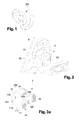
- the helmet 5 comprises, in a manner known per se and as illustrated on the figure 2 , a band headband said band 51 secured to two earphones 52, the strip 51 being shaped to grip the head of the driver, so that each earpiece is placed to cover an ear.
- the strip 51 is relatively wide so as to have a bearing surface on the top of the head sufficient to carry the weight of the headphones without generating excessive pressure.
- the embodiments of the device are described in the context of a device intended to be fixed on a wall 6 of a cockpit of an aircraft, for example as illustrated in FIG. figure 2 on a cladding of a structural amount, but the invention is also applicable to any type of transport vehicle subject to external events, such as for example turbulence, vertical accelerations and or vibrations that can eject the helmet of its support .
- the receiving face 111 presents, in a view from above as illustrated on the figure 3b , preferably a substantially rectangular shape, of width I.
- the external holding member 12 is integral at a first end 121 with a front end, called the first longitudinal edge 113, of the receiving plate 11.
- the internal fastening member 13 is secured at a first end 131 of a rear end, said second longitudinal edge 115, of the receiving plate 11, opposite to the first longitudinal edge 113 along the width I.
- the plates forming the inner and outer members 12 and 13 are substantially parallel to each other on either side of the longitudinal edges 113, 115 of the receiving plate.
- the device 1 further comprises, at a free end 132 of the internal member 13, opposite the first end 131, an anti-release element 14 which closes all or part of the opening 17, forming a housing 171 at least partially closed for the helmet 5.
- the anti-clearance element 14 has a stable sealing position of at least one surface sufficient to prevent the passage of the strip 51 through the opening 17.
- the characteristics of said anti-release element in particular its rigidity, are such that that it remains in the stable stopping position when subjected to a force exerted by the helmet under the effect of inertial forces following, for example, turbulence. Its characteristics are however such that it can be moved by a manual action of the pilot in a release position allowing the passage of the headband of the helmet through said opening.
- the anti-clearance element 14 may be a strap, a free end opposite an end attached to the device 1, at the outer holding member, is fixed to the wall 6 by means of a press button, for example in order to seal the opening 17.
- the anti-release element is made of a material having elastic deformation properties, for example an elastomer. It has a sufficient rigidity to prevent the release of the helmet itself out of the hook, but low enough to be able to manually insert the helmet into its housing in the hook or remove it by deforming said anti-release element.
- the anti-clearance element 14 is a tongue extending in the stable sealing position substantially parallel to the receiving face 111, in a plane joining the respective free ends 132, 122 internal 13 and external 12.
- the anti-release element is for example made of an elastomeric material, such as rubber, capable of deforming.
- the device 1 comprises spring-type articulation means at the free end 132 of the internal member 13, allowing the anti-clearance element 14 to tilt under the effect of a thrust then a return to its initial stable stopping position when the thrust is no longer exerted.
- the spring hinge means are calibrated so that a manual action can tilt without difficulty the anti-release element for introducing or extracting the headband of the helmet of the device but so that a force exerted by the headband of the helmet under the effect of an acceleration can not tilt the anti-release element.
- the anti-release element 14 is positioned on the inner member 13, but said anti-release element can also be positioned on a free end 122 of the external member 12, opposite the first end 121, not illustrated solution.
- the receiving face 111 is shaped in its length to fit the rounded shape of the headband 51 of the helmet 5.
- the outer member 12 has a rounded contour.
- the device 1 is fixed to the wall 6 by any conventional means, in particular by gluing or screwing.
- the internal member 13 has at least one attachment hole 135 adapted to be traversed by a fixing screw.
- the outer member 12 has at least one, preferably a number identical to that of the orifices 135 of the inner member 13, orifice 125, placed opposite said orifices 135 and of diameter adapted to the passage of a clamping tool of the screw.
- the inner 13 and outer 12 each comprise two holes for the passage and fixing the device to the wall by two screws.
- the internal member 13 is no longer fixedly secured to the second longitudinal edge 115 of the receiving plate 11 and the device 1 advantageously comprises, at the first end 131 of the internal member 13, sliding means of the receiving plate, for example a box 15, preferably substantially homothetic receiving plate 11.
- the box 15 is assembled to the second longitudinal edge 115 of the receiving plate and is made so that the receiving plate 11 is mounted sliding in the box forming a slide.
- the receiving plate 11 is at least partially retractable inside the box 15.
- width I of the housing 171 is variable according to the relative position of the receiving plate 11 relative to the sliding means.
- the box 15 is advantageously integrated in the thickness of said wall (not shown in the figures), in particular in the cladding of said wall.
- the receiving plate 11 has a dimension in the direction of minimum sliding, necessary to sufficiently distance the outer member 12 of the inner member 13 so that the strip 51 of the helmet 5 can be introduced through the opening 17, if appropriate by retracting the anti-release element.
- the device 1 further comprises automatic means 16 for retracting the receiving plate 11 substantially completely integrated in the box 15 and stretchable so as to allow, in an output position of the receiving plate, a width 1 between the internal and at least equal to a width of the strip 51 of the helmet 5.
- the automatic retraction means 16 are for example a return spring and they are preferably positioned on the side of a second face 112 of the receiving plate 11, opposite to the receiving face 111, between a rear end 151 of the box, opposite a front end 152 secured to the internal member 13, and the outer member 12.
- Said automatic retracting means 16 are in a retracted or slightly stretched position when the external member 12 is substantially against the internal member 13, when the helmet is not placed on the device, and in a stretched position when the member external 12 is remote from said internal fastening member 13, in particular when the helmet is placed on the device.
- the anti-clearance element 14 is placed in a folded position so that the internal 13 and outer 12 members are substantially separated by a thickness of the anti-release element 14 which has been folded against the internal fixing member, advantageously under the action of the external member 12.
- the anti-clearance element 14 may have a slight inclination with respect to the internal fixing member 13 towards the receiving face 111 so as to facilitate the folding of said anti-release element when the external member 12 returns towards the internal member 13 under the effect of automatic retraction means 16.
- the automatic retraction means 16 are chosen so that a manual action can easily remove the external member 12 of the internal member 13 to introduce the headband of the helmet into the housing 15 but also so that said automatic retracting means can not relax and spread the outer member 12 under the effect of turbulence alone, including when a helmet is placed on the device.
- the traction forces to be exerted are such that they can be exerted without difficulty using one hand to pull the external member 12.
- the second face 112 of the receiving plate 11 is shaped so as to be substantially identical to the receiving face 111 so as to accommodate and hide, under the rounded portion, the automatic retraction means 16.
- the device 1 When the pilot uses his helmet, the device 1 is in a so-called retracted position.
- the external member 12 is as close as possible to the internal member 13, as illustrated on the Figures 4b and 4c .
- the anti-release element 14 returns to its initial position of closing the housing 171.
- the pilot sufficiently removes the external member 12 so that the opening 17, where appropriate in combination with at least partial erasure of the anti-release element 14, is sufficient to allow the introduction of the strip 51 into the housing 171.
- the driver When the opening is sufficient, while retaining the outer member 12 in position, the driver introduces the strip 51 into the opening 17.
- the pilot releases the external member 12.
- the automatic retraction means 16 tend to bring the internal 13 and outer 12 organs closer again until they are immobilized. relative to each other by the headband, as shown on the figure 5 .
- the automatic retraction means 16 thus make it possible, in addition to the anti-release element 14, to improve the quality of the maintenance of the strip 51 in the housing 15.
- This embodiment advantageously makes it possible, in addition to improving the maintenance of the helmet in the device, to reduce the size of the device when said device does not support the helmet.
- This reduction in size makes it possible on the one hand to limit the risk of injury and / or shocks to the head during movements in an area close to the device, and on the other hand to bring greater robustness to the device by reducing the risk of deterioration of the device under the effect of a shock.
- This embodiment also advantageously makes it possible, while maintaining the effectiveness of the anti-release element, to adapt the device to different widths of headband.
- the present invention is not limited to the examples described above. Those skilled in the art are able to adapt the shape and section of the device elements to undescribed shapes and sections.
- the device according to the invention thus allows a pilot to securely store his helmet when he wishes.
Abstract
Description
La présente invention appartient au domaine des dispositifs utilisés pour le support d'un casque à bandeau serre-tête sur une structure lorsque le casque n'est pas utilisé. L'invention trouve plus particulièrement application pour le support de tels casques sur des structures de véhicules soumis à de fortes accélérations verticales et / ou des vibrations, qui sont susceptibles de provoquer l'éjection du casque hors du support.The present invention belongs to the field of devices used to support a headband helmet on a structure when the helmet is not used. The invention finds particular application for the support of such helmets on vehicle structures subjected to high vertical accelerations and / or vibrations, which are likely to cause the ejection of the helmet out of the support.
Le domaine d'application préféré de l'invention, qui sera décrit plus précisément dans la présente description, est celui des aéronefs. L'invention s'applique cependant également de la même manière à tout autre véhicule susceptible d'être soumis à des vibrations, tels par exemple que des véhicules de chantier.The preferred field of application of the invention, which will be described more precisely in the present description, is that of aircraft. The invention however also applies in the same way to any other vehicle likely to be subjected to vibration, such as for example construction vehicles.
L'invention s'applique aussi bien aux casques audio qu'aux casques radio ou aux casques anti-bruit ou à tout autre type de casque muni d'un bandeau serre-tête utilisés dans les véhicules.The invention applies both to headphones, radio headphones or noise-canceling headphones or any other type of helmet with a headband used in vehicles.
A bord des véhicules, plus particulièrement à bord des aéronefs, les pilotes utilisent un casque radio leur permettant de communiquer avec le reste de l'équipage et les services du contrôle aérien, tout en restant isolés du bruit extérieur pour une meilleure qualité d'écoute. Le pilote étant conduit à mettre et à retirer occasionnellement son casque radio au sol et ou au cours d'un vol, ce casque est préférablement posé à proximité du pilote, sans pour autant occasionner de gêne pour l'accès du pilote aux organes de pilotage et aux panneaux de commande et sans que celui-ci ne puisse tomber et soit difficile à reprendre lorsque le pilote en a besoin.In vehicles, especially on board aircraft, pilots use a radio headset to communicate with the rest of the crew and air traffic control services, while remaining isolated from outside noise for better listening quality. . As the pilot is required to occasionally put on and take off his radio helmet on the ground and during a flight, this helmet is preferably placed near the pilot, without causing any inconvenience to the pilot's access to the piloting devices. and to the control panels and without it being able to fall and be difficult to pick up when the pilot needs it.
De préférence, le casque est posé sur un support situé au niveau des habillages du poste de pilotage, de préférence dans une zone à hauteur de tête du pilote, lorsqu'il est en position assise.Preferably, the helmet is placed on a support located at the cockpit upholstery, preferably in an area at head height of the pilot, when in a sitting position.
Pour poser et tenir le casque, les supports existants utilisés à bord des aéronefs sont en général des supports du type des crochets 100, métalliques ou en matériau composite, tels que par exemple celui illustré
Cependant, ces supports peuvent s'avérer insuffisants pour assurer le maintien du casque lorsque l'avion est soumis à des accélérations verticales et ou des turbulences car le casque peut à ce moment là être éjecté du support et retomber dans un endroit plus ou moins accessible par le pilote depuis son siège, voire de manière inopportune soit sur le pilote lui-même, soit sur des équipements de bord, occasionnant une gêne éventuelle alors qu'une attention particulière est recommandée de la part du pilote durant ces phases de vol.However, these supports may be insufficient to ensure the maintenance of the helmet when the aircraft is subjected to vertical acceleration and or turbulence because the helmet can at that moment be ejected from the support and fall in a more or less accessible place by the pilot from his seat, or even inappropriately either on the pilot himself, or on equipment on board, causing possible discomfort when special attention is recommended by the pilot during these phases of flight.
La présente invention vise à améliorer les conditions de pilotage des pilotes pendant le vol et à assurer l'accessibilité du casque en toutes circonstances, principalement lors de turbulences et ou de fortes accélérations verticales.The present invention aims to improve the pilot's flying conditions during flight and to ensure the accessibility of the helmet in all circumstances, mainly during turbulence and or strong vertical accelerations.
Pour cela, elle propose un dispositif pour le support d'un casque le long d'une paroi d'un véhicule, qui comporte un crochet présentant :
- un socle de réception d'un bandeau du casque, destiné à être fixé transversalement à la paroi par une extrémité arrière, et étant solidaire à une extrémité avant opposée d'un organe externe de maintien dudit bandeau sur ledit socle, et
- une ouverture, entre l'extrémité arrière du socle et l'organe externe de maintien, de largeur I au moins égale à une largeur du bandeau, autorisant le passage du bandeau vers le socle ou en éloignement du socle.
- a base for receiving a headband of the helmet, intended to be fixed transversely to the wall by a rear end, and being integral with an opposite front end of an outer member for holding said headband on said base, and
- an opening, between the rear end of the base and the outer holding member, of width I at least equal to a width of the strip, allowing the passage of the strip to the base or away from the base.
Ledit dispositif comporte un élément anti-dégagement obturant l'ouverture sur au moins une largeur suffisante pour empêcher le passage du bandeau à travers l'ouverture. Cet élément anti-dégagement est apte à être déplacé par une action manuelle, directement sur l'élément anti-dégagement ou par l'intermédiaire du casque, dans une position de libération pour permettre le passage du bandeau à travers ladite ouverture.Said device comprises an anti-release element closing the opening over at least a width sufficient to prevent the passage of the strip through the opening. This anti-release element is able to be moved by a manual action, directly on the anti-release element or through the helmet, in a release position to allow the passage of the strip through said opening.
Cet élément anti-dégagement bloque avantageusement le bandeau du casque dans sa position supportée par le crochet, et ce tant qu'un effort volontaire suffisamment important n'est pas exercé sur lui en libération de l'ouverture. Il est avantageusement configuré de manière à résister à des chocs ponctuels exercés sur lui par le casque secoué par des mouvements du véhicule. Le casque est ainsi maintenu en permanence sur le crochet. Il est toujours facilement accessible à l'utilisateur et il ne risque en outre pas de gêner le pilote durant les opérations de pilotage, en étant éjecté du crochet n'importe où dans le poste de pilotage.This anti-disengagement element advantageously blocks the headband of the helmet in its position supported by the hook, and as long as a sufficiently strong voluntary effort is not exerted on it in liberation of the opening. It is advantageously configured to withstand shocks punctualities exerted on him by the helmet shaken by movements of the vehicle. The helmet is thus permanently maintained on the hook. It is always easily accessible to the user and it also does not risk to interfere with the pilot during piloting operations, being ejected from the hook anywhere in the cockpit.
Dans un exemple de réalisation, l'élément anti-dégagement est une languette s'étendant sensiblement parallèlement au socle.In an exemplary embodiment, the anti-release element is a tongue extending substantially parallel to the base.
Dans des modes de réalisation préférés de l'invention, l'élément anti-dégagement est apte à être replié en direction du socle de manière à libérer l'ouverture du passage du bandeau, et / ou déplié à l'opposé de ce socle, pour le même résultat.In preferred embodiments of the invention, the anti-release element is able to be folded in the direction of the base so as to release the opening of the passage of the strip, and / or unfolded opposite this base, for the same result.
Selon une caractéristique préférée de l'invention, l'élément anti-dégagement occupe une partie seulement de la largeur I de l'ouverture entre l'extrémité arrière du socle et l'organe de maintien.According to a preferred feature of the invention, the anti-release element occupies only part of the width I of the opening between the rear end of the base and the holding member.
De préférence, l'élément anti-dégagement est réalisé dans un matériau présentant des propriétés de déformation élastique.Preferably, the anti-release element is made of a material having elastic deformation properties.
Dans une forme de réalisation, le dispositif comporte un organe interne de fixation du socle à la paroi, solidaire du socle au niveau de l'extrémité arrière de ce dernier.In one embodiment, the device comprises an internal fixing member of the base to the wall, secured to the base at the rear end thereof.
De préférence, afin d'assurer une meilleure réception du bandeau sur le socle, ledit socle est une plaque conformée pour épouser localement la forme du bandeau du casque.Preferably, in order to ensure better reception of the strip on the base, said base is a plate shaped to fit locally the shape of the headband of the helmet.
De préférence, afin de diminuer le risque de blessure pour le pilote, l'organe externe de maintien présente un contour arrondi.Preferably, in order to reduce the risk of injury to the pilot, the outer holding member has a rounded contour.
Dans un mode de réalisation amélioré, le socle est au moins en partie rétractable à l'intérieur d'un caisson du dispositif destiné à être disposé dans une épaisseur de la paroi. Le caisson est solidaire du socle par l'extrémité arrière dudit socle. Le socle est de préférence monté coulissant dans ledit caisson formant glissière. Le dispositif comporte en outre des moyens automatiques de rétractation, de préférence sensiblement entièrement, du socle dans le caisson, de manière à amener, en absence de sollicitation externe et de présence d'un casque, l'organe externe de maintien à une distance de l'extrémité arrière du socle correspondant à une largeur I de l'ouverture au moins inférieure à une largeur du bandeau du casque destiné à être maintenu dans le dispositif, et qui sont étirables de manière à déployer le socle hors du caisson de sorte que la largeur I ait au moins ladite largeur du bandeau.In an improved embodiment, the base is at least partially retractable inside a box of the device intended to be disposed in a thickness of the wall. The box is secured to the base by the rear end of said base. The base is preferably slidably mounted in said slide box. The device further comprises automatic retraction means, preferably substantially entirely, of the base in the box, so as to bring, in the absence of external solicitation and presence of a helmet, the external holding member at a distance from the rear end of the base corresponding to a width I of the opening at least less than a width of the headband of the helmet intended to be maintained in the device, and which are stretchable so as to extend the base out of the box so that the width I has at least said width of the strip.
Lorsque le bandeau est positionné sur le crochet, il se produit alors, par l'effet de la rétractation du socle dans le caisson, un pincement du bandeau entre l'organe externe de maintien et la paroi, qui a pour effet de maintenir encore plus solidement le bandeau sur le crochet.When the strip is positioned on the hook, it then occurs, by the effect of the retraction of the base in the box, a pinching of the strip between the outer holding member and the wall, which has the effect of maintaining even more securely the headband on the hook.
Dans des modes de réalisation préférés de l'invention, en l'absence de casque, lorsque le socle est ramené sensiblement entièrement dans le caisson, l'élément anti-dégagement est avantageusement replié entre l'organe externe de maintien et un organe interne de fixation à la paroi.In preferred embodiments of the invention, in the absence of a helmet, when the base is brought back substantially entirely into the casing, the anti-disengagement element is advantageously folded between the external holding member and an internal member of the casing. fixing to the wall.
L'invention concerne également un véhicule équipé sur au moins une paroi d'un dispositif pour le support d'un casque tel que décrit ci-avant.The invention also relates to a vehicle equipped on at least one wall of a device for supporting a helmet as described above.
La description détaillée de l'invention est faite en référence aux figures qui représentent :
-
Figure 1 , déjà citée, un exemple d'un dispositif pour le support d'un casque suivant l'art antérieur, -
Figure 2 , une illustration d'un casque stocké dans un support suivant un premier mode de réalisation de l'invention, -
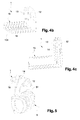
Figure 3a, b, c , différentes vues d'un premier mode de réalisation du support de casque suivant l'invention, -
Figure 4a, b, c , différentes vues d'un second mode de réalisation d'un support de casque suivant l'invention. -
Figure 5 , une illustration d'un casque stocké dans un support suivant le second mode de réalisation de l'invention.
-
Figure 1 , already mentioned, an example of a device for supporting a helmet according to the prior art, -
Figure 2 , an illustration of a helmet stored in a support according to a first embodiment of the invention, -
Figure 3a, b, c , different views of a first embodiment of the helmet support according to the invention, -
Figure 4a, b, c , different views of a second embodiment of a helmet support according to the invention. -
Figure 5 , an illustration of a helmet stored in a support according to the second embodiment of the invention.
Un dispositif suivant l'invention est destiné à recevoir et supporter, contre une paroi d'un véhicule, un casque radio d'un pilote que ce dernier doit conserver à proximité lorsqu'il ne le porte pas sur lui.A device according to the invention is intended to receive and support, against a wall of a vehicle, a radio headset of a driver that the latter must keep close when not wearing it.
Dans la description le terme casque est utilisé pour désigner un tel casque radio.In the description the term headset is used to designate such radio headset.
Le casque 5 comporte, de manière connue en soi et comme illustré sur la
Pour des raisons de confort essentiellement, le bandeau 51 est relativement large de sorte à présenter une surface d'appui sur le sommet de la tête suffisante pour porter le poids des écouteurs sans générer de pression excessive.For reasons of comfort essentially, the
Les exemples de réalisation du dispositif, illustré sur les
Suivant l'invention, le dispositif 1 pour le support d'un casque sur une paroi 6 comporte, comme illustré sur les
- un socle, présentant de préférence la forme d'une plaque, dite plaque de
réception 11, comportant une première face, dite face deréception 111, pour recevoir une partie sensiblement centrale dubandeau 51 ducasque 5, - un organe externe 12, présentant également de préférence la forme d'une plaque, de maintien de la partie centrale du bandeau sur la face de
réception 111 en formant une butée lors d'un déplacement du bandeau sur la plaque de réception dans une direction opposée à la direction de laparoi 6, l'ensemble plaque de réception - organe externe de maintien formant uncrochet 10, - un organe interne 13, présentant de préférence la forme d'une plaque, de fixation du
dispositif 1 sur laparoi 6, - une
ouverture 17, pour introduire et ou retirer le bandeau de la face deréception 111, située entre l'organe externe 12 et l'organe interne 13.
- a base, preferably having the shape of a plate, said receiving
plate 11, comprising a first face, said receivingface 111, for receiving a substantially central portion of theheadband 51 of thehelmet 5, - an
outer member 12, also preferably in the form of a plate, for holding the central portion of the strip on the receivingface 111 forming a stop during a movement of the strip on the receiving plate in an opposite direction in the direction of thewall 6, the receiving plate assembly - external holding member forming ahook 10, - an
internal member 13, preferably having the shape of a plate, fixing thedevice 1 on thewall 6, - an
opening 17, for introducing and or removing the strip from thereceiving face 111, situated between theexternal member 12 and theinternal member 13.
La face de réception 111 présente, sur une vue de dessus comme illustrée sur la
L'organe externe de maintien 12 est solidaire à une première extrémité 121 d'une extrémité avant, dite premier bord longitudinal 113, de la plaque de réception 11.The
L'organe interne de fixation 13, est solidaire à une première extrémité 131 d'une extrémité arrière, dite second bord longitudinal 115, de la plaque de réception 11, opposée au premier bord longitudinal 113 suivant la largeur I.The
Dans une forme non limitative de réalisation, afin de réduire l'encombrement du dispositif dans le poste de pilotage, les plaques formant les organes interne 13 et externe 12 sont sensiblement parallèles entre elles de part et d'autre des bords longitudinaux 113, 115 de la plaque de réception.In a non-limiting embodiment, in order to reduce the size of the device in the cockpit, the plates forming the inner and
Avantageusement, pour éviter le risque d'un dégagement du casque hors du dispositif en cas de turbulence ou d'accélération verticale, le dispositif 1 comporte en outre, au niveau d'une extrémité libre 132 de l'organe interne 13, opposée à la première extrémité 131, un élément anti-dégagement 14 qui obture tout ou partie de l'ouverture 17, formant un logement 171 au moins partiellement refermé pour le casque 5.Advantageously, to avoid the risk of a release of the helmet out of the device in case of turbulence or vertical acceleration, the
L'élément anti-dégagement 14 comporte une position d'obturation stable d'au moins une surface suffisante pour empêcher le passage du bandeau 51 à travers l'ouverture 17. Les caractéristiques dudit élément anti-dégagement, en particulier sa rigidité, sont telles que celui-ci reste dans la position d'obturation stable lorsqu'il est soumis à une force exercée par le casque sous l'effet des forces d'inertie suite, par exemple, à une turbulence. Ses caractéristiques sont cependant telles qu'il peut être déplacé par une action manuelle du pilote dans une position de libération permettant le passage du bandeau du casque à travers ladite ouverture.The
L'élément anti-dégagement 14 peut être une sangle dont une extrémité libre opposée à une extrémité fixée au dispositif 1, au niveau de l'organe de maintien externe, se fixe à la paroi 6 au moyen par exemple d'un bouton pression, de manière à obturer l'ouverture 17.The
Dans un exemple de réalisation, l'élément anti-dégagement est réalisé dans un matériau présentant des propriétés de déformation élastiques, par exemple un élastomère. Il présente une rigidité suffisante pour empêcher le dégagement du casque par lui-même hors du crochet, mais suffisamment faible pour pouvoir introduire manuellement le casque dans son logement dans le crochet ou l'en retirer en déformant ledit élément anti-dégagement.In an exemplary embodiment, the anti-release element is made of a material having elastic deformation properties, for example an elastomer. It has a sufficient rigidity to prevent the release of the helmet itself out of the hook, but low enough to be able to manually insert the helmet into its housing in the hook or remove it by deforming said anti-release element.
Dans un exemple préférentiel de réalisation, l'élément anti-dégagement 14 est une languette s'étendant dans la position d'obturation stable sensiblement parallèlement à la face de réception 111, dans un plan rejoignant les extrémités libres respectives 132, 122, des organes interne 13 et externe 12.In a preferred embodiment, the
L'élément anti-dégagement est par exemple réalisé dans un matériau élastomère, tel que le caoutchouc, apte à se déformer.The anti-release element is for example made of an elastomeric material, such as rubber, capable of deforming.
Dans un autre exemple de réalisation, le dispositif 1 comporte des moyens d'articulation à ressort au niveau de l'extrémité libre 132 de l'organe interne 13, permettant un basculement de l'élément anti-dégagement 14 sous l'effet d'une poussée puis un retour dans sa position initiale d'obturation stable lorsque la poussée n'est plus exercée.In another exemplary embodiment, the
Les moyens d'articulation à ressort sont tarés de sorte qu'une action manuelle puisse faire basculer sans difficulté l'élément anti-dégagement pour introduire ou extraire le bandeau du casque du dispositif mais de sorte qu'une force exercée par le bandeau du casque sous l'effet d'une accélération ne puisse faire basculer l'élément anti-dégagement.The spring hinge means are calibrated so that a manual action can tilt without difficulty the anti-release element for introducing or extracting the headband of the helmet of the device but so that a force exerted by the headband of the helmet under the effect of an acceleration can not tilt the anti-release element.
Par commodité d'accès pour le pilote, l'élément anti-dégagement 14 est positionné sur l'organe interne 13 mais ledit élément anti-dégagement peut également être positionné sur une extrémité libre 122 de l'organe externe 12, opposée à la première extrémité 121, solution non illustrée.For convenience of access for the pilot, the
De préférence, afin d'augmenter la surface de contact du casque sur le dispositif et ainsi d'apporter un maintien amélioré en position du casque pendant les différentes phases de vol ainsi que sous conditions turbulentes et de limiter des risques d'endommager le bandeau, la face de réception 111 est conformée dans sa longueur pour épouser la forme arrondie du bandeau 51 du casque 5.Preferably, in order to increase the contact surface of the helmet on the device and thus to provide improved support in position of the helmet during the various phases of flight and under turbulent conditions and to limit risks of damaging the strip, the receiving
De préférence, afin de limiter le risque de blessure et ou de chocs pour le pilote et afin de faciliter le passage du bandeau lorsque le casque est placé sur ou retiré du dispositif, l'organe externe 12 présente un contour arrondi.Preferably, in order to limit the risk of injury and / or shock to the pilot and to facilitate the passage of the headband when the headset is placed on or removed from the device, the
Le dispositif 1 est fixé à la paroi 6 par tout moyen conventionnel, notamment par collage ou vissage.The
Dans un exemple de réalisation où le dispositif est vissé dans la paroi, l'organe interne 13 présente au moins un orifice de fixation 135 apte à être traversé par une vis de fixation. L'organe externe 12 présente au moins un, de préférence un nombre identique à celui des orifices 135 de l'organe interne 13, orifice 125, placé en regard desdits orifices 135 et de diamètre adapté au passage d'un outil de serrage de la vis de fixation.In an exemplary embodiment where the device is screwed into the wall, the
Sur les
Dans un mode de réalisation amélioré, illustré sur les
Ainsi la largeur I du logement 171 est variable suivant la position relative de la plaque de réception 11 par rapport aux moyens de coulissement.Thus the width I of the
Lorsque le dispositif 1 est fixé sur une paroi 6, le caisson 15 est avantageusement intégré dans l'épaisseur de ladite paroi (non représentée sur les figures), en particulier dans l'habillage de ladite paroi.When the
La plaque de réception 11 présente une dimension suivant la direction de coulissement minimale, nécessaire pour écarter suffisamment l'organe externe 12 de l'organe interne 13 afin que le bandeau 51 du casque 5 puisse être introduit par l'ouverture 17, le cas échéant en escamotant l'élément anti-dégagement.The receiving
Le dispositif 1 comporte en outre des moyens automatiques 16 de rétractation de la plaque de réception 11 sensiblement entièrement intégrés dans le caisson 15 et étirables de sorte à autoriser, dans une position sortie de la plaque de réception, une largeur 1 entre les organes interne et externe au moins égale à une largeur du bandeau 51 du casque 5. Les moyens automatiques de rétractation 16 sont par exemple un ressort de rappel et ils sont de préférence positionnés du coté d'une deuxième face 112 de la plaque de réception 11, opposée à la face de réception 111, entre une extrémité arrière 151 du caisson, opposée à une extrémité avant 152 solidaire de l'organe interne 13, et l'organe externe 12.The
Lesdits moyens automatiques de rétractation 16 sont dans une position rétractée ou faiblement étirée lorsque l'organe externe 12 est sensiblement contre l'organe interne 13, lorsque le casque n'est pas posé sur le dispositif, et dans une position étirée lorsque l'organe externe 12 est éloigné dudit organe interne de fixation 13, en particulier lorsque le casque est posé sur le dispositif.Said automatic retracting means 16 are in a retracted or slightly stretched position when the
Dans la position rétractée, les organes interne 13 et externe 12 sont rapprochés sous l'effet des moyens de rétractation 16 et ledit organe externe est maintenu en butée, dans la configuration illustrée, contre l'élément anti-dégagement 14.In the retracted position, the inner and
Dans un mode de réalisation préféré qui minimise les dimensions du dispositif lorsque le casque est retiré, l'élément anti-dégagement 14 est placé dans une position repliée de sorte que les organes interne 13 et externe 12 sont séparés sensiblement par une épaisseur de l'élément anti-dégagement 14 qui a été replié contre l'organe interne de fixation, avantageusement sous l'action de l'organe externe 12.In a preferred embodiment which minimizes the dimensions of the device when the helmet is removed, the
De préférence, l'élément anti-dégagement 14 peut présenter une légère inclinaison par rapport à l'organe interne de fixation 13 vers la face de réception 111 de sorte à faciliter le repliement dudit élément anti-dégagement lorsque l'organe externe 12 revient vers l'organe interne 13 sous l'effet des moyens automatiques de rétractation 16.Preferably, the
Les moyens automatiques de rétractation 16 sont choisis de sorte qu'une action manuelle puisse écarter sans difficulté l'organe externe 12 de l'organe interne 13 pour introduire le bandeau du casque dans le logement 15 mais également de sorte que lesdits moyens automatiques de rétractation ne puissent se détendre et écarter l'organe externe 12 sous l'effet des turbulences seules, y compris lorsqu'un casque est posé sur le dispositif.The automatic retraction means 16 are chosen so that a manual action can easily remove the
Avantageusement, les efforts de traction à exercer sont tels qu'ils peuvent être exercés sans difficulté en utilisant une seule main pour tirer l'organe externe 12.Advantageously, the traction forces to be exerted are such that they can be exerted without difficulty using one hand to pull the
Dans une forme de réalisation, la deuxième face 112 de la plaque de réception 11 est conformée de sorte à être sensiblement identique à la face de réception 111 de sorte à loger et masquer, sous la partie arrondie, les moyens automatiques de rétractation 16.In one embodiment, the
Lorsque le pilote utilise son casque, le dispositif 1 est dans une position dite rétractée. L'organe externe 12 est au plus près de l'organe interne 13, comme illustré sur les
Lorsque le pilote pose son casque sur le dispositif 1, il tire sur l'organe externe 12. Les moyens automatiques de rétractation 16, qui maintenaient l'organe externe 12 sensiblement contre l'organe interne 13, sont étirés.When the driver puts his helmet on the
Simultanément à l'écartement de l'organe externe 12 par rapport à l'organe interne 13, l'élément anti-dégagement 14 revient dans sa position initiale d'obturation du logement 171.Simultaneously with the spacing of the
Le pilote éloigne suffisamment l'organe externe 12 de sorte que l'ouverture 17, le cas échéant en association avec un effacement au moins partiel de l'élément anti-dégagement 14, soit suffisante pour permettre l'introduction du bandeau 51 dans le logement 171.The pilot sufficiently removes the
Lorsque l'ouverture est suffisante, tout en retenant l'organe externe 12 en position, le pilote introduit le bandeau 51 dans l'ouverture 17.When the opening is sufficient, while retaining the
Lorsque le bandeau 51 est posé sur la face de réception 111 du dispositif 1, le pilote relâche l'organe externe 12. Les moyens automatiques de rétractation 16 tendent à rapprocher à nouveau les organes interne 13 et externe 12 jusqu'à être immobilisés l'un par rapport à l'autre par le bandeau, comme illustré sur la
Les moyens automatiques de rétractation 16 permettent ainsi, en complément de l'élément anti-dégagement 14, d'améliorer la qualité du maintien du bandeau 51 dans le logement 15.The automatic retraction means 16 thus make it possible, in addition to the
Ce mode de réalisation permet avantageusement, outre d'améliorer le maintien du casque dans le dispositif, de réduire l'encombrement du dispositif lorsque ledit dispositif ne supporte pas le casque. Cette réduction d'encombrement permet d'une part de limiter le risque de blessure et / ou de chocs à la tête lors de mouvements dans une zone proche du dispositif, et d'autre part d'apporter une meilleure robustesse au dispositif en diminuant le risque de détérioration du dispositif sous l'effet d'un choc.This embodiment advantageously makes it possible, in addition to improving the maintenance of the helmet in the device, to reduce the size of the device when said device does not support the helmet. This reduction in size makes it possible on the one hand to limit the risk of injury and / or shocks to the head during movements in an area close to the device, and on the other hand to bring greater robustness to the device by reducing the risk of deterioration of the device under the effect of a shock.
Ce mode de réalisation permet également avantageusement, tout en conservant l'efficacité de l'élément anti-dégagement, d'adapter le dispositif à différentes largeurs de bandeau de casque.This embodiment also advantageously makes it possible, while maintaining the effectiveness of the anti-release element, to adapt the device to different widths of headband.
La présente invention ne se limite pas aux exemples décrits ci-dessus. L'homme du métier est en mesure d'adapter la forme et la section des éléments du dispositif à des formes et sections non décrites.The present invention is not limited to the examples described above. Those skilled in the art are able to adapt the shape and section of the device elements to undescribed shapes and sections.
Le dispositif suivant l'invention permet ainsi à un pilote de stocker de manière sécurisée son casque lorsqu'il le souhaite.The device according to the invention thus allows a pilot to securely store his helmet when he wishes.
Claims (10)
Applications Claiming Priority (1)
| Application Number | Priority Date | Filing Date | Title |
|---|---|---|---|
| FR0900404A FR2941659B1 (en) | 2009-01-30 | 2009-01-30 | SECURE DEVICE FOR SUPPORTING A HELMET |
Publications (2)
| Publication Number | Publication Date |
|---|---|
| EP2213517A1 true EP2213517A1 (en) | 2010-08-04 |
| EP2213517B1 EP2213517B1 (en) | 2014-12-17 |
Family
ID=40512578
Family Applications (1)
| Application Number | Title | Priority Date | Filing Date |
|---|---|---|---|
| EP10151574.0A Active EP2213517B1 (en) | 2009-01-30 | 2010-01-25 | Device for holding a headphone |
Country Status (3)
| Country | Link |
|---|---|
| US (1) | US8272548B2 (en) |
| EP (1) | EP2213517B1 (en) |
| FR (1) | FR2941659B1 (en) |
Cited By (2)
| Publication number | Priority date | Publication date | Assignee | Title |
|---|---|---|---|---|
| US20100200631A1 (en) * | 2009-01-30 | 2010-08-12 | Airbus Operations (Societe Par Actions Simplifiee) | Secured device for a headset support |
| WO2015035433A3 (en) * | 2013-09-06 | 2015-04-30 | Marc Timothy Turk | Mountiwq means |
Families Citing this family (5)
| Publication number | Priority date | Publication date | Assignee | Title |
|---|---|---|---|---|
| US8820597B2 (en) * | 2012-08-01 | 2014-09-02 | Ford Global Technologies, Llc | Vehicle garment hook and guard mounting assembly |
| US9561755B2 (en) | 2012-08-01 | 2017-02-07 | Ford Global Technologies, Llc | Vehicle garment hook assembly |
| US9701256B2 (en) * | 2014-12-09 | 2017-07-11 | Handstands Promo, Llc | Mounting clip |
| US10065565B2 (en) * | 2017-01-26 | 2018-09-04 | Ford Global Technologies, Llc | Linear-travel hanger assembly |
| US11192503B2 (en) * | 2019-07-08 | 2021-12-07 | Toyota Motor Engineering & Manufacturing North America, Inc. | Integrated gravitational anti-spill container system |
Citations (8)
| Publication number | Priority date | Publication date | Assignee | Title |
|---|---|---|---|---|
| US2258200A (en) * | 1940-04-19 | 1941-10-07 | John C Baird | Snap hook |
| FR1163467A (en) * | 1956-11-13 | 1958-09-26 | Carabiner holder and its applications, in particular dog leashes | |
| FR1481309A (en) * | 1966-05-13 | 1967-05-19 | J Grateau Et Cie Sa Ets | Carabiner holder |
| US4720028A (en) * | 1985-04-19 | 1988-01-19 | Honda Giken Kogyo Kabushiki Kaisha | Device for hanging a garment in a vehicle |
| US5507423A (en) * | 1995-02-28 | 1996-04-16 | Prince Corporation | Push-push vehicle clothes hook assembly |
| US5890689A (en) * | 1997-05-01 | 1999-04-06 | Johnson; Jason G. | Automobile garment hanger |
| US6397435B1 (en) * | 1999-04-22 | 2002-06-04 | Lear Corporation | Handle assembly with integrated hook |
| US20020113465A1 (en) * | 2001-02-22 | 2002-08-22 | Takahiko Inari | Assist grip |
Family Cites Families (4)
| Publication number | Priority date | Publication date | Assignee | Title |
|---|---|---|---|---|
| US3424418A (en) * | 1967-02-14 | 1969-01-28 | Ford Motor Co | Automatically retractable coat hook |
| DE29607310U1 (en) * | 1996-04-23 | 1996-07-04 | E Lead Electronic Co Ltd | Holder for a hearing device in a motor vehicle |
| JP4109984B2 (en) * | 2002-12-26 | 2008-07-02 | 株式会社ニフコ | Hook device |
| FR2941659B1 (en) * | 2009-01-30 | 2012-08-17 | Airbus France | SECURE DEVICE FOR SUPPORTING A HELMET |
-
2009
- 2009-01-30 FR FR0900404A patent/FR2941659B1/en not_active Expired - Fee Related
-
2010
- 2010-01-22 US US12/692,465 patent/US8272548B2/en active Active
- 2010-01-25 EP EP10151574.0A patent/EP2213517B1/en active Active
Patent Citations (8)
| Publication number | Priority date | Publication date | Assignee | Title |
|---|---|---|---|---|
| US2258200A (en) * | 1940-04-19 | 1941-10-07 | John C Baird | Snap hook |
| FR1163467A (en) * | 1956-11-13 | 1958-09-26 | Carabiner holder and its applications, in particular dog leashes | |
| FR1481309A (en) * | 1966-05-13 | 1967-05-19 | J Grateau Et Cie Sa Ets | Carabiner holder |
| US4720028A (en) * | 1985-04-19 | 1988-01-19 | Honda Giken Kogyo Kabushiki Kaisha | Device for hanging a garment in a vehicle |
| US5507423A (en) * | 1995-02-28 | 1996-04-16 | Prince Corporation | Push-push vehicle clothes hook assembly |
| US5890689A (en) * | 1997-05-01 | 1999-04-06 | Johnson; Jason G. | Automobile garment hanger |
| US6397435B1 (en) * | 1999-04-22 | 2002-06-04 | Lear Corporation | Handle assembly with integrated hook |
| US20020113465A1 (en) * | 2001-02-22 | 2002-08-22 | Takahiko Inari | Assist grip |
Cited By (5)
| Publication number | Priority date | Publication date | Assignee | Title |
|---|---|---|---|---|
| US20100200631A1 (en) * | 2009-01-30 | 2010-08-12 | Airbus Operations (Societe Par Actions Simplifiee) | Secured device for a headset support |
| US8272548B2 (en) * | 2009-01-30 | 2012-09-25 | Airbus Operations | Secured device for a headset support |
| WO2015035433A3 (en) * | 2013-09-06 | 2015-04-30 | Marc Timothy Turk | Mountiwq means |
| USD789774S1 (en) | 2013-09-06 | 2017-06-20 | Marc Timothy Turk | Mounting bracket |
| USD841636S1 (en) | 2013-09-06 | 2019-02-26 | Marc Timothy Turk | Case for a smartphone, cellular phone, tablet, GPS device, or the like |
Also Published As
| Publication number | Publication date |
|---|---|
| EP2213517B1 (en) | 2014-12-17 |
| US20100200631A1 (en) | 2010-08-12 |
| US8272548B2 (en) | 2012-09-25 |
| FR2941659A1 (en) | 2010-08-06 |
| FR2941659B1 (en) | 2012-08-17 |
Similar Documents
| Publication | Publication Date | Title |
|---|---|---|
| EP2213517B1 (en) | Device for holding a headphone | |
| EP3283374B1 (en) | Device for supporting a portable device for an aeroplane seat | |
| EP0682885B1 (en) | Device for retaining a helmet on the occiput | |
| CA2349764C (en) | Enhancement for safety helmet | |
| FR2956566A1 (en) | PROTECTIVE HELMET HAVING AN ELECTRONIC CONNECTION DEVICE | |
| FR2477485A1 (en) | MIRROR ARRANGEMENT TO BE MOUNTED ON A VEHICLE DOOR AND MOUNTING METHOD | |
| EP1544035A1 (en) | Vehicle body front portion assembly with improved fastening and position adjusting means, and vehicle provided with such an assembly | |
| FR2909329A1 (en) | Flat inner fitting element e.g. table, arrangement for motor vehicle, has flat inner fitting element movable between storage and usage positions, and maintained at specific height in front of passenger, when element is in usage position | |
| FR2975643A1 (en) | Seat e.g. individual seat, for car, has protective cover mounted movably on anchoring rod between closed position, in which cover is in continuity with backrest and prevents access to rod, and open position to release access to rod | |
| WO1997025832A1 (en) | Improvement to an electroacoustic communication device for use on protective headgear | |
| FR2792890A1 (en) | ARMREST CONSOLE FOR A MOTOR VEHICLE INTERIOR | |
| WO2011116948A1 (en) | Inflatable airbag flap hinged to a dashboard by means of a link configured to release an additional length of link upon the opening of the flap | |
| EP0532378A1 (en) | Restraining device for the back-seat middle passenger of a vehicle | |
| EP2352674B1 (en) | Aircraft engine assembly including a rigid modular structure for a mounting pylon3 | |
| WO2014199047A1 (en) | Footrest incorporating means for storing tyre repair equipment | |
| FR3065684A1 (en) | TRIM ASSEMBLY COMPRISING A DEPLOYABLE PIECE | |
| EP2900523B1 (en) | Seatbelt winder support with programmed deformation | |
| EP0945302A1 (en) | Mass dissipating device, seat structure, seat and vehicle equipped with this device | |
| EP3154826A1 (en) | Arrangement of a dashboard trim element of a motor vehicle on a supporting element of said dashboard | |
| FR2989942A1 (en) | System for locking anchoring leg of removable organ i.e. canopy in boot of car, has thrust units movable between active position in which fastener is blocked, and in inactive position in which fastener is able to be freely rotated | |
| WO2023036549A1 (en) | Pivoting car seat | |
| FR3070650B1 (en) | DEVICE FOR FIXING A BAY AMOUNT EQUIPPED WITH AN AIRBAG | |
| WO2024047297A1 (en) | Seat for a motor vehicle | |
| FR3118730A1 (en) | SEAT RAISER FOR A VEHICLE SEAT, WITH TENSION REDUCTION DURING A FRONT IMPACT | |
| EP1547858A1 (en) | Armrest for a motor vehicle seat, console and seat therewith |
Legal Events
| Date | Code | Title | Description |
|---|---|---|---|
| PUAI | Public reference made under article 153(3) epc to a published international application that has entered the european phase |
Free format text: ORIGINAL CODE: 0009012 |
|
| AK | Designated contracting states |
Kind code of ref document: A1 Designated state(s): AT BE BG CH CY CZ DE DK EE ES FI FR GB GR HR HU IE IS IT LI LT LU LV MC MK MT NL NO PL PT RO SE SI SK SM TR |
|
| AX | Request for extension of the european patent |
Extension state: AL BA RS |
|
| 17P | Request for examination filed |
Effective date: 20110125 |
|
| 17Q | First examination report despatched |
Effective date: 20110223 |
|
| GRAP | Despatch of communication of intention to grant a patent |
Free format text: ORIGINAL CODE: EPIDOSNIGR1 |
|
| INTG | Intention to grant announced |
Effective date: 20140926 |
|
| GRAS | Grant fee paid |
Free format text: ORIGINAL CODE: EPIDOSNIGR3 |
|
| GRAA | (expected) grant |
Free format text: ORIGINAL CODE: 0009210 |
|
| AK | Designated contracting states |
Kind code of ref document: B1 Designated state(s): AT BE BG CH CY CZ DE DK EE ES FI FR GB GR HR HU IE IS IT LI LT LU LV MC MK MT NL NO PL PT RO SE SI SK SM TR |
|
| REG | Reference to a national code |
Ref country code: GB Ref legal event code: FG4D Free format text: NOT ENGLISH |
|
| REG | Reference to a national code |
Ref country code: CH Ref legal event code: EP |
|
| REG | Reference to a national code |
Ref country code: IE Ref legal event code: FG4D Free format text: LANGUAGE OF EP DOCUMENT: FRENCH |
|
| REG | Reference to a national code |
Ref country code: AT Ref legal event code: REF Ref document number: 701632 Country of ref document: AT Kind code of ref document: T Effective date: 20150115 |
|
| REG | Reference to a national code |
Ref country code: DE Ref legal event code: R096 Ref document number: 602010020990 Country of ref document: DE Effective date: 20150205 |
|
| PG25 | Lapsed in a contracting state [announced via postgrant information from national office to epo] |
Ref country code: NO Free format text: LAPSE BECAUSE OF FAILURE TO SUBMIT A TRANSLATION OF THE DESCRIPTION OR TO PAY THE FEE WITHIN THE PRESCRIBED TIME-LIMIT Effective date: 20150317 Ref country code: FI Free format text: LAPSE BECAUSE OF FAILURE TO SUBMIT A TRANSLATION OF THE DESCRIPTION OR TO PAY THE FEE WITHIN THE PRESCRIBED TIME-LIMIT Effective date: 20141217 Ref country code: LT Free format text: LAPSE BECAUSE OF FAILURE TO SUBMIT A TRANSLATION OF THE DESCRIPTION OR TO PAY THE FEE WITHIN THE PRESCRIBED TIME-LIMIT Effective date: 20141217 |
|
| REG | Reference to a national code |
Ref country code: LT Ref legal event code: MG4D |
|
| PG25 | Lapsed in a contracting state [announced via postgrant information from national office to epo] |
Ref country code: GR Free format text: LAPSE BECAUSE OF FAILURE TO SUBMIT A TRANSLATION OF THE DESCRIPTION OR TO PAY THE FEE WITHIN THE PRESCRIBED TIME-LIMIT Effective date: 20150318 Ref country code: LV Free format text: LAPSE BECAUSE OF FAILURE TO SUBMIT A TRANSLATION OF THE DESCRIPTION OR TO PAY THE FEE WITHIN THE PRESCRIBED TIME-LIMIT Effective date: 20141217 Ref country code: HR Free format text: LAPSE BECAUSE OF FAILURE TO SUBMIT A TRANSLATION OF THE DESCRIPTION OR TO PAY THE FEE WITHIN THE PRESCRIBED TIME-LIMIT Effective date: 20141217 Ref country code: SE Free format text: LAPSE BECAUSE OF FAILURE TO SUBMIT A TRANSLATION OF THE DESCRIPTION OR TO PAY THE FEE WITHIN THE PRESCRIBED TIME-LIMIT Effective date: 20141217 |
|
| REG | Reference to a national code |
Ref country code: AT Ref legal event code: MK05 Ref document number: 701632 Country of ref document: AT Kind code of ref document: T Effective date: 20141217 |
|
| PG25 | Lapsed in a contracting state [announced via postgrant information from national office to epo] |
Ref country code: NL Free format text: LAPSE BECAUSE OF FAILURE TO SUBMIT A TRANSLATION OF THE DESCRIPTION OR TO PAY THE FEE WITHIN THE PRESCRIBED TIME-LIMIT Effective date: 20141217 |
|
| PG25 | Lapsed in a contracting state [announced via postgrant information from national office to epo] |
Ref country code: EE Free format text: LAPSE BECAUSE OF FAILURE TO SUBMIT A TRANSLATION OF THE DESCRIPTION OR TO PAY THE FEE WITHIN THE PRESCRIBED TIME-LIMIT Effective date: 20141217 Ref country code: SK Free format text: LAPSE BECAUSE OF FAILURE TO SUBMIT A TRANSLATION OF THE DESCRIPTION OR TO PAY THE FEE WITHIN THE PRESCRIBED TIME-LIMIT Effective date: 20141217 Ref country code: RO Free format text: LAPSE BECAUSE OF FAILURE TO SUBMIT A TRANSLATION OF THE DESCRIPTION OR TO PAY THE FEE WITHIN THE PRESCRIBED TIME-LIMIT Effective date: 20141217 Ref country code: CZ Free format text: LAPSE BECAUSE OF FAILURE TO SUBMIT A TRANSLATION OF THE DESCRIPTION OR TO PAY THE FEE WITHIN THE PRESCRIBED TIME-LIMIT Effective date: 20141217 Ref country code: ES Free format text: LAPSE BECAUSE OF FAILURE TO SUBMIT A TRANSLATION OF THE DESCRIPTION OR TO PAY THE FEE WITHIN THE PRESCRIBED TIME-LIMIT Effective date: 20141217 Ref country code: PT Free format text: LAPSE BECAUSE OF FAILURE TO SUBMIT A TRANSLATION OF THE DESCRIPTION OR TO PAY THE FEE WITHIN THE PRESCRIBED TIME-LIMIT Effective date: 20150417 |
|
| REG | Reference to a national code |
Ref country code: CH Ref legal event code: PL |
|
| PG25 | Lapsed in a contracting state [announced via postgrant information from national office to epo] |
Ref country code: AT Free format text: LAPSE BECAUSE OF FAILURE TO SUBMIT A TRANSLATION OF THE DESCRIPTION OR TO PAY THE FEE WITHIN THE PRESCRIBED TIME-LIMIT Effective date: 20141217 Ref country code: PL Free format text: LAPSE BECAUSE OF FAILURE TO SUBMIT A TRANSLATION OF THE DESCRIPTION OR TO PAY THE FEE WITHIN THE PRESCRIBED TIME-LIMIT Effective date: 20141217 Ref country code: LU Free format text: LAPSE BECAUSE OF FAILURE TO SUBMIT A TRANSLATION OF THE DESCRIPTION OR TO PAY THE FEE WITHIN THE PRESCRIBED TIME-LIMIT Effective date: 20150125 Ref country code: IS Free format text: LAPSE BECAUSE OF FAILURE TO SUBMIT A TRANSLATION OF THE DESCRIPTION OR TO PAY THE FEE WITHIN THE PRESCRIBED TIME-LIMIT Effective date: 20150417 |
|
| REG | Reference to a national code |
Ref country code: DE Ref legal event code: R097 Ref document number: 602010020990 Country of ref document: DE |
|
| PG25 | Lapsed in a contracting state [announced via postgrant information from national office to epo] |
Ref country code: MC Free format text: LAPSE BECAUSE OF FAILURE TO SUBMIT A TRANSLATION OF THE DESCRIPTION OR TO PAY THE FEE WITHIN THE PRESCRIBED TIME-LIMIT Effective date: 20141217 |
|
| PLBE | No opposition filed within time limit |
Free format text: ORIGINAL CODE: 0009261 |
|
| STAA | Information on the status of an ep patent application or granted ep patent |
Free format text: STATUS: NO OPPOSITION FILED WITHIN TIME LIMIT |
|
| PG25 | Lapsed in a contracting state [announced via postgrant information from national office to epo] |
Ref country code: DK Free format text: LAPSE BECAUSE OF FAILURE TO SUBMIT A TRANSLATION OF THE DESCRIPTION OR TO PAY THE FEE WITHIN THE PRESCRIBED TIME-LIMIT Effective date: 20141217 Ref country code: CH Free format text: LAPSE BECAUSE OF NON-PAYMENT OF DUE FEES Effective date: 20150131 Ref country code: LI Free format text: LAPSE BECAUSE OF NON-PAYMENT OF DUE FEES Effective date: 20150131 |
|
| REG | Reference to a national code |
Ref country code: IE Ref legal event code: MM4A |
|
| 26N | No opposition filed |
Effective date: 20150918 |
|
| PG25 | Lapsed in a contracting state [announced via postgrant information from national office to epo] |
Ref country code: IT Free format text: LAPSE BECAUSE OF FAILURE TO SUBMIT A TRANSLATION OF THE DESCRIPTION OR TO PAY THE FEE WITHIN THE PRESCRIBED TIME-LIMIT Effective date: 20141217 |
|
| REG | Reference to a national code |
Ref country code: FR Ref legal event code: PLFP Year of fee payment: 7 |
|
| PG25 | Lapsed in a contracting state [announced via postgrant information from national office to epo] |
Ref country code: IE Free format text: LAPSE BECAUSE OF NON-PAYMENT OF DUE FEES Effective date: 20150125 |
|
| PG25 | Lapsed in a contracting state [announced via postgrant information from national office to epo] |
Ref country code: SI Free format text: LAPSE BECAUSE OF FAILURE TO SUBMIT A TRANSLATION OF THE DESCRIPTION OR TO PAY THE FEE WITHIN THE PRESCRIBED TIME-LIMIT Effective date: 20141217 |
|
| PG25 | Lapsed in a contracting state [announced via postgrant information from national office to epo] |
Ref country code: MT Free format text: LAPSE BECAUSE OF FAILURE TO SUBMIT A TRANSLATION OF THE DESCRIPTION OR TO PAY THE FEE WITHIN THE PRESCRIBED TIME-LIMIT Effective date: 20141217 |
|
| REG | Reference to a national code |
Ref country code: FR Ref legal event code: PLFP Year of fee payment: 8 |
|
| PG25 | Lapsed in a contracting state [announced via postgrant information from national office to epo] |
Ref country code: HU Free format text: LAPSE BECAUSE OF FAILURE TO SUBMIT A TRANSLATION OF THE DESCRIPTION OR TO PAY THE FEE WITHIN THE PRESCRIBED TIME-LIMIT; INVALID AB INITIO Effective date: 20100125 Ref country code: BG Free format text: LAPSE BECAUSE OF FAILURE TO SUBMIT A TRANSLATION OF THE DESCRIPTION OR TO PAY THE FEE WITHIN THE PRESCRIBED TIME-LIMIT Effective date: 20141217 Ref country code: SM Free format text: LAPSE BECAUSE OF FAILURE TO SUBMIT A TRANSLATION OF THE DESCRIPTION OR TO PAY THE FEE WITHIN THE PRESCRIBED TIME-LIMIT Effective date: 20141217 |
|
| PG25 | Lapsed in a contracting state [announced via postgrant information from national office to epo] |
Ref country code: CY Free format text: LAPSE BECAUSE OF FAILURE TO SUBMIT A TRANSLATION OF THE DESCRIPTION OR TO PAY THE FEE WITHIN THE PRESCRIBED TIME-LIMIT Effective date: 20141217 |
|
| PG25 | Lapsed in a contracting state [announced via postgrant information from national office to epo] |
Ref country code: BE Free format text: LAPSE BECAUSE OF NON-PAYMENT OF DUE FEES Effective date: 20150131 |
|
| PG25 | Lapsed in a contracting state [announced via postgrant information from national office to epo] |
Ref country code: TR Free format text: LAPSE BECAUSE OF FAILURE TO SUBMIT A TRANSLATION OF THE DESCRIPTION OR TO PAY THE FEE WITHIN THE PRESCRIBED TIME-LIMIT Effective date: 20141217 |
|
| REG | Reference to a national code |
Ref country code: FR Ref legal event code: PLFP Year of fee payment: 9 |
|
| PG25 | Lapsed in a contracting state [announced via postgrant information from national office to epo] |
Ref country code: MK Free format text: LAPSE BECAUSE OF FAILURE TO SUBMIT A TRANSLATION OF THE DESCRIPTION OR TO PAY THE FEE WITHIN THE PRESCRIBED TIME-LIMIT Effective date: 20141217 |
|
| PGFP | Annual fee paid to national office [announced via postgrant information from national office to epo] |
Ref country code: FR Payment date: 20230124 Year of fee payment: 14 |
|
| PGFP | Annual fee paid to national office [announced via postgrant information from national office to epo] |
Ref country code: GB Payment date: 20230119 Year of fee payment: 14 Ref country code: DE Payment date: 20230123 Year of fee payment: 14 |