EP2213511A1 - Vehicle lighting system - Google Patents
Vehicle lighting system Download PDFInfo
- Publication number
- EP2213511A1 EP2213511A1 EP09176758A EP09176758A EP2213511A1 EP 2213511 A1 EP2213511 A1 EP 2213511A1 EP 09176758 A EP09176758 A EP 09176758A EP 09176758 A EP09176758 A EP 09176758A EP 2213511 A1 EP2213511 A1 EP 2213511A1
- Authority
- EP
- European Patent Office
- Prior art keywords
- lighting apparatus
- area
- vehicle
- main
- light
- Prior art date
- Legal status (The legal status is an assumption and is not a legal conclusion. Google has not performed a legal analysis and makes no representation as to the accuracy of the status listed.)
- Granted
Links
Images






Classifications
-
- B—PERFORMING OPERATIONS; TRANSPORTING
- B60—VEHICLES IN GENERAL
- B60Q—ARRANGEMENT OF SIGNALLING OR LIGHTING DEVICES, THE MOUNTING OR SUPPORTING THEREOF OR CIRCUITS THEREFOR, FOR VEHICLES IN GENERAL
- B60Q1/00—Arrangement of optical signalling or lighting devices, the mounting or supporting thereof or circuits therefor
- B60Q1/02—Arrangement of optical signalling or lighting devices, the mounting or supporting thereof or circuits therefor the devices being primarily intended to illuminate the way ahead or to illuminate other areas of way or environments
- B60Q1/04—Arrangement of optical signalling or lighting devices, the mounting or supporting thereof or circuits therefor the devices being primarily intended to illuminate the way ahead or to illuminate other areas of way or environments the devices being headlights
- B60Q1/18—Arrangement of optical signalling or lighting devices, the mounting or supporting thereof or circuits therefor the devices being primarily intended to illuminate the way ahead or to illuminate other areas of way or environments the devices being headlights being additional front lights
-
- B—PERFORMING OPERATIONS; TRANSPORTING
- B60—VEHICLES IN GENERAL
- B60Q—ARRANGEMENT OF SIGNALLING OR LIGHTING DEVICES, THE MOUNTING OR SUPPORTING THEREOF OR CIRCUITS THEREFOR, FOR VEHICLES IN GENERAL
- B60Q1/00—Arrangement of optical signalling or lighting devices, the mounting or supporting thereof or circuits therefor
- B60Q1/0029—Spatial arrangement
- B60Q1/0041—Spatial arrangement of several lamps in relation to each other
-
- B—PERFORMING OPERATIONS; TRANSPORTING
- B60—VEHICLES IN GENERAL
- B60Q—ARRANGEMENT OF SIGNALLING OR LIGHTING DEVICES, THE MOUNTING OR SUPPORTING THEREOF OR CIRCUITS THEREFOR, FOR VEHICLES IN GENERAL
- B60Q1/00—Arrangement of optical signalling or lighting devices, the mounting or supporting thereof or circuits therefor
- B60Q1/26—Arrangement of optical signalling or lighting devices, the mounting or supporting thereof or circuits therefor the devices being primarily intended to indicate the vehicle, or parts thereof, or to give signals, to other traffic
- B60Q1/2661—Arrangement of optical signalling or lighting devices, the mounting or supporting thereof or circuits therefor the devices being primarily intended to indicate the vehicle, or parts thereof, or to give signals, to other traffic mounted on parts having other functions
- B60Q1/2665—Arrangement of optical signalling or lighting devices, the mounting or supporting thereof or circuits therefor the devices being primarily intended to indicate the vehicle, or parts thereof, or to give signals, to other traffic mounted on parts having other functions on rear-view mirrors
-
- B—PERFORMING OPERATIONS; TRANSPORTING
- B60—VEHICLES IN GENERAL
- B60R—VEHICLES, VEHICLE FITTINGS, OR VEHICLE PARTS, NOT OTHERWISE PROVIDED FOR
- B60R1/00—Optical viewing arrangements; Real-time viewing arrangements for drivers or passengers using optical image capturing systems, e.g. cameras or video systems specially adapted for use in or on vehicles
- B60R1/12—Mirror assemblies combined with other articles, e.g. clocks
- B60R1/1207—Mirror assemblies combined with other articles, e.g. clocks with lamps; with turn indicators
-
- B—PERFORMING OPERATIONS; TRANSPORTING
- B62—LAND VEHICLES FOR TRAVELLING OTHERWISE THAN ON RAILS
- B62J—CYCLE SADDLES OR SEATS; AUXILIARY DEVICES OR ACCESSORIES SPECIALLY ADAPTED TO CYCLES AND NOT OTHERWISE PROVIDED FOR, e.g. ARTICLE CARRIERS OR CYCLE PROTECTORS
- B62J6/00—Arrangement of optical signalling or lighting devices on cycles; Mounting or supporting thereof; Circuits therefor
- B62J6/02—Headlights
- B62J6/022—Headlights specially adapted for motorcycles or the like
- B62J6/024—Switching between high and low beam
-
- B—PERFORMING OPERATIONS; TRANSPORTING
- B60—VEHICLES IN GENERAL
- B60Q—ARRANGEMENT OF SIGNALLING OR LIGHTING DEVICES, THE MOUNTING OR SUPPORTING THEREOF OR CIRCUITS THEREFOR, FOR VEHICLES IN GENERAL
- B60Q2400/00—Special features or arrangements of exterior signal lamps for vehicles
- B60Q2400/30—Daytime running lights [DRL], e.g. circuits or arrangements therefor
Definitions
- the present invention relates to a vehicle lighting system suitable for use in motorcycles and other small-sized vehicles.
- a known vehicle lighting system includes a plurality of lighting apparatuses that are disposed on a front surface of a motorcycle so as to be reminiscent of a "face,” thereby enhancing conspicuity of the motorcycle (see, for example, Patent Document No. JP 2006-298045 ).
- the most important part for representing the "face” is an "eye.”
- the known art represents the "eye" by representing the black part of the eye and the white part of the eye with the lighting apparatuses.
- the lighting apparatuses representing the black part of the eye and the white part of the eye are disposed relatively close to each other. This necessitates consideration for, for example, the shape or the lighting method to allow a third person to know the black part of the eye from the white part of the eye easily even when viewing from a distance. This makes the structure of the lighting system tend to be complicated.
- glare a phenomenon in which an excessively bright local spot existing within a field of view makes an object to be viewed hard to view
- glare tends to occur at nighttime particularly in areas around a main lighting apparatus emitting an intense light, such as a headlamp, so that an outline of a light-emitting surface of each lighting apparatus blurs, resulting in all of the light-emitting surfaces emitting a single light beam.
- a glare area an area where the glare is readily generated (a glare area) is defined, and an auxiliary lighting apparatus of a steadily lighting type such as a position lamp is disposed by avoiding the area to inhibit the outline of the light-emitting surface of each lighting apparatus from blurring to be fused
- an aspect of the present invention provides a vehicle lighting system having a main lighting apparatus including a main light-emitting surface that illuminates a vehicle forward area and flashing type lighting apparatuses disposed laterally sideways at right and left of the main lighting apparatus in a vehicle front view.
- a glare area with a width y as expressed in an expression given below when the main lighting apparatus has a luminous intensity of x is defined outside an outline of the main light-emitting surface in the vehicle front view; and an auxiliary lighting apparatus disposition area, in which an auxiliary lighting apparatus of a steadily lighting type different from the flashing type lighting apparatuses is disposed, is set upwardly of the main lighting apparatus and outside the glare area.
- the auxiliary lighting apparatus disposition area is set at a position that is, in the vehicle front view, upward of an upper end of the glare area and laterally outside a left or right end of the glare area.
- the auxiliary lighting apparatus disposition area is set, in the vehicle front view, within an area defined between a first inclined line extending obliquely upwardly at an angle of 35 degrees relative to a vertical line from a centroid of the main light-emitting surface and a second inclined line extending obliquely upwardly at an angle of 55 degrees relative to the vertical line from the centroid, and outside an area defined by a width 2y outside the outline of the main light-emitting surface.
- the auxiliary lighting apparatus disposition area is an area surrounded by line segments specified by coordinates as detailed below when the centroid of the main light-emitting surface in the vehicle front view is defined as an origin and W [mm] is an abscissa and D [mm] is an ordinate.
- the auxiliary lighting apparatus has a light source disposed in the auxiliary lighting apparatus disposition area.
- the auxiliary lighting apparatus emits light in an annular shape in the vehicle front view and a center of the annular shape is disposed in the auxiliary lighting apparatus disposition area.
- the auxiliary lighting apparatus emits light in a line segment shape inclined so as to be disposed more upwardly at outer sides in a vehicle width direction in the vehicle front view, the auxiliary lighting apparatus being disposed at an angle of 0 to 60 degrees relative to a vertical line and having at least a length of 150 [mm].
- the main lighting apparatus and the flashing type lighting apparatus emit light of different colors from each other and the auxiliary lighting apparatus emits light of a similar color as that of the light emitted by the main lighting apparatus.
- the auxiliary lighting apparatuses are disposed symmetrically about the main lighting apparatus.
- the vehicle includes a low beam lamp illuminating a relatively nearby area and a high beam lamp illuminating a remote area relative to the area illuminated by the low beam lamp and the main lighting apparatus is the low beam lamp.
- the main lighting apparatus includes a low beam lamp illuminating a relatively nearby area and a high beam lamp illuminating a remote area relative to the area illuminated by the low beam lamp and the auxiliary lighting apparatus disposition area is set corresponding to the glare area when the low beam lamp is turned ON.
- the vehicle front surface is made to be readily pronounced of a "face,” having the main lighting apparatus as a “mouth” and the auxiliary lighting apparatuses as “eyes,” so that conspicuity of the vehicle can be easily enhanced.
- the auxiliary lighting apparatuses being disposed outside the glare area of the main lighting apparatus, help inhibit the outline of the light-emitting surface of each lighting apparatus from blurring to be fused.
- the vehicle front surface can therefore be readily pronounced of a "face,” so that the conspicuity of the vehicle can be easily enhanced.
- the steadily lighting type auxiliary lighting apparatus is provided in addition to the flashing type lighting apparatuses. This results in the "mouth” and the "eyes" being steadily lit up, which helps make the vehicle front surface reminiscent of a "face.”
- the auxiliary lighting apparatuses are disposed upwardly of the upper end of the glare area of the main lighting apparatus and laterally outside apart from each other.
- the auxiliary lighting apparatuses are disposed at appropriate positions equivalent to the "eyes" of the "face,” of which the vehicle front face is pronounced. This makes the vehicle front surface readily pronounced of the "face,” so that the conspicuity of the vehicle can be easily enhanced.
- the auxiliary lighting apparatus is disposed even further apart from the glare area of the main lighting apparatus.
- the auxiliary lighting apparatuses are disposed at even more appropriate positions equivalent to the "eyes" of the "face,” of which the vehicle front face is pronounced. The conspicuity of the vehicle can therefore be even more easily enhanced.
- the light source of the auxiliary lighting apparatus emits an even more intense light and the contrast with surrounding areas is more readily pronounced of the black part of the "eye.” This makes the vehicle front surface readily pronounced of the "face” effectively.
- the center of the annular shape emits light less intense than that emitted by the light-emitting surface of the annular shape. This contrast is more readily pronounced of the black part of the "eye,” which makes the vehicle front surface readily pronounced of the "face” effectively.
- the auxiliary lighting apparatus is arranged to emit light in an oblique line segment shape and have an adequate length.
- the arrangements help make the "eye” more easily recognizable. This makes the vehicle front surface readily pronounced of the "face,” so that the conspicuity of the vehicle can be easily enhanced.
- the main lighting apparatus and the auxiliary lighting apparatus are made to emit light of a color different from that of a flasher or other flashing type lighting apparatus.
- the auxiliary lighting apparatuses as the "eyes” are disposed symmetrically about the main lighting apparatus as the "mouth.” This makes the vehicle front surface even more readily pronounced of the "face.”
- the main lighting apparatus is a low beam lamp. This allows a high beam lamp to be disposed without regard to the position of the auxiliary lighting apparatus, which easily enhances the degree of freedom in disposing the high beam lamp.
- the vehicle front surface is reminiscent of the "face" when the low beam lamp is turned ON. This makes it easier to enhance conspicuity of the vehicle.
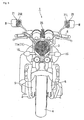
- Figs. 1 to 5 are front views (vehicle front views) showing a motorcycle 1 mounted with a vehicle lighting system according to an embodiment of the present invention as viewed from the front of the vehicle.
- the lighting system includes a single-bulb headlamp (hereinafter referred to as a "main lighting apparatus") 11 disposed at a center in a vehicle lateral direction to illuminate a vehicle forward area and left and right front flashers or hazard lamps (hereinafter referred to as flashing type lighting apparatuses) 15 disposed laterally sideways of the main lighting apparatus 11.
- the lighting system further includes steadily lighting type left and right position lamps (hereinafter referred to as auxiliary lighting apparatuses) 21 to 24 disposed upwardly of the main lighting apparatus 11 at left and right symmetrical positions.
- auxiliary lighting apparatuses steadily lighting type left and right position lamps
- main lighting apparatus 11 and the auxiliary lighting apparatuses 21 to 24 are disposed so as to make a vehicle front surface reminiscent of a "face,” so that the motorcycle 1 is easily identifiable from an outside and conspicuity of the motorcycle 1 can thereby be enhanced.
- the vehicle lighting system includes the pair of left and right auxiliary lighting apparatuses that are equivalent to "eyes" of the "face,” of which the vehicle front face is reminiscent, and the single main lighting apparatus that is equivalent to a "mouth” of the “face.”
- the main lighting apparatus 11 and the auxiliary lighting apparatuses 21 to 24 light up steadily when a main switch of the motorcycle 1 is turned ON (or, for example, a lamp switch is further turned ON) and the flashing type lighting apparatuses 15 flash off and on when the main switch of the motorcycle 1 is turned ON and, for example, a flasher switch or a hazard switch is turned ON.
- reference numeral 3 denotes a head pipe disposed at a front end of a vehicle body frame, for steerably supporting a front wheel suspension system.
- Reference numeral 4 denotes a front wheel.
- Reference numeral 5 denotes a front fork having a lower end portion that journals the front wheel 4.
- Reference numeral 6 denotes a handlebar for steering the front wheel 4.
- each of the lighting apparatuses shown in Figs. 1 to 5 is mounted on, and rotatable with, the front wheel suspension system. At least one of these lighting apparatuses may instead be fixedly mounted on the vehicle body frame via, for example, a stay or a cowling.
- the main lighting apparatus may be a dual-bulb type or a type having three or more bulbs including a plurality of light-emitting surfaces.
- the main lighting apparatus 11 has a single lighting body in which a high beam lamp (driving headlamp) or a low beam lamp (meeting headlamp) is selected for use; however, the high beam lamp and the low beam lamp may instead be formed in respective individual lighting bodies.
- the main lighting apparatus 11 and the auxiliary lighting apparatuses 21 to 24 emit light of a similar color, such as, for example, white
- the flashing type lighting apparatuses 15 emit light of a color different from that of the main lighting apparatus 11 and the auxiliary lighting apparatuses 21 to 24, such as, for example, orange.
- the low beam lamp of the main lighting apparatus 11 has a luminous intensity equivalent to 750 [cd] (55 [W]) when the low beam lamp is turned ON.
- an area (glare area) G outside an outline OL of a main light-emitting surface 11a in which glare (a phenomenon in which an excessively bright local spot existing within a field of view makes an object to be viewed hard to view) tends more easily to occur, is defined by a width y as expressed in expression 1 shown below when the luminous intensity of the main light-emitting surface 11 a is x. Referring, for example, to Fig.
- reference numeral H/L indicates a centroid (and the position of a light source (bulb), the center of a reflector, and a light-emitting center according to the embodiment of the present invention) of the main light-emitting surface 11a of the main lighting apparatus 11.
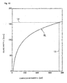
- Fig. 16 is a graph showing a relationship between the luminous intensity x [cd] of the main lighting apparatus 11 of a round-eye, single-bulb type laid off on the abscissa and the glare width y [mm] laid off on the ordinate.
- a curve CL represents approximate data obtained experimentally by the inventor and is expressed by the expression 1.
- auxiliary light-emitting surfaces 21 L, 21 R of the auxiliary lighting apparatuses 21 are disposed within the glare area G outside the main lighting apparatus 11. This may cause an outline of the light-emitting surface of each lighting apparatus to blur, so that all of the light-emitting surfaces seem to be combined together to emit a single light. To make the vehicle front surface reminiscent of the "face" effectively, therefore, it is desirable that the light-emitting surfaces of the auxiliary lighting apparatuses be disposed outside the glare area G in the vehicle front view.
- "1.8 times" of area A means a ratio of an identification rate of the motorcycle 1 to be described later for a case in which the auxiliary lighting apparatus is disposed in area A and turned ON to the identification ratio of the motorcycle 1 for a case in which only the main lighting apparatus 11 is turned ON.
- the identification rate of the motorcycle 1 having the auxiliary lighting apparatus in area A in addition to the main lighting apparatus is 1.8 times as much as the identification rate of the motorcycle 1 having only the main lighting apparatus.
- the identification rate is 2.0 times; if the auxiliary lighting apparatus is disposed in area C shown in Fig.
- Figs. 6(b) and 7 to 9 are graphs having W of Fig. 6(a) on the abscissa and D of Fig. 6(a) on the ordinate. Note also that, in Figs. 6(b) and 7 to 9 , areas are shown only on the left-hand side of the vehicle; however, each of those areas is to exist also on the right-hand side of the vehicle; specifically, the areas are to exist symmetrically.
- the auxiliary lighting apparatus is to have a luminous intensity equivalent to 16 [cd] (equivalent to a 5-[W] incandescent lamp).
- the identification rates are distributed independently of the size of the glare area and the distribution remains the same regardless of whether the glare area is large or small as long as the auxiliary lighting apparatus is disposed outside the glare area.
- the statement that "the auxiliary lighting apparatus is disposed in each area” means that at least part of the light-emitting surface of the auxiliary lighting apparatus exists in each area in the vehicle front view and, preferably, the bulb (light source, light-emitting center, centroid) of the auxiliary lighting apparatus exists in each area. If the auxiliary lighting apparatus has a plurality of light-emitting surfaces within each area, the centroid of each light-emitting surface is combined together with each other to serve as a centroid of the whole. Note also that the light-emitting surface includes a light source screen, such as a monitor screen.
- an area H1 in which the auxiliary lighting apparatus is disposed is set at a position that is, in the vehicle front view, upward of an upper end of the glare area G and laterally outside a left or right end of the glare area G. Then, disposing the light-emitting surface of the auxiliary lighting apparatus in the area H1 achieves an identification rate that is 2.0 times or more as much as the identification rate when the motorcycle 1 has only the main lighting apparatus 11.
- reference numeral L3 denotes a line segment indicating the upper end position of the glare area G and reference numeral L4 denotes a line segment indicating the left/right end position of the glare area G.
- the area H1 in which the auxiliary lighting apparatus is disposed is to be set within a range of 500 [mm] in a horizontal direction from the centroid H/L and 450 [mm] upward in a vertical direction therefrom.
- an area H2 in which the auxiliary lighting apparatus is disposed is set, in the vehicle front view, within an area defined between a first inclined line L1 extending obliquely upwardly, at an angle of 35 degrees relative to a vertical line, from the centroid H/L of the main light-emitting surface 11 a and a second inclined line L2 extending obliquely upwardly, at an angle of 55 degrees relative to the vertical line, from the centroid H/L, and outside an area 2G defined by a width 2y outside the outline OL of the main light-emitting surface 11 a.
- Disposing the light-emitting surface of the auxiliary lighting apparatus in the area H2 achieves an identification rate that is 2.2 times or more as much as the identification rate when the motorcycle 1 has only the main lighting apparatus 11.
- the area H2 in which the auxiliary lighting apparatus is disposed is to be set within a range of 500 [mm] in the horizontal direction from the centroid H/L and 450 [mm] upward in the vertical direction therefrom.
- an area (which substantially corresponds to the above-mentioned area D) surrounded by line segments specified by coordinates as detailed below when the centroid H/L of the main light-emitting surface 11 a in the vehicle front view is defined as an origin and D [mm] is the ordinate and W [mm] is the abscissa, is set as an area H3 in which the auxiliary lighting apparatus is disposed. Then, disposing the auxiliary lighting apparatus in the area H3 achieves an identification rate that is substantially 2.4 times as much as the identification rate when the motorcycle 1 has only the main lighting apparatus 11.
- the lighting system shown in Fig. 1 typically includes the auxiliary lighting apparatuses 21 having the light-emitting surfaces 21 R, 21 L, each having a rectangular shape in the vehicle front view, disposed on front surfaces of housings of left and right rearview mirrors M.
- reference numeral BL denotes a bulb (light source) of the auxiliary lighting apparatus 21.
- the lighting system shown in Fig. 2 typically includes the auxiliary lighting apparatuses 22 having light-emitting surfaces 22R, 22L, each having an annular shape in the vehicle front view, disposed on front surfaces of housings of left and right rearview mirrors M.
- reference numeral C denotes a center of each of the auxiliary light-emitting surface 22R, 22L.
- a graph shown in Fig. 11 shows, in sequence from the left to the right, the identification rate of the motorcycle having the auxiliary lighting apparatuses 21 that have the rectangular light-emitting surfaces 21 R, 21 L, the identification rate of a motorcycle having auxiliary lighting apparatuses 21' that have similar light-emitting surfaces disposed additionally on the lateral outside of the light-emitting surfaces 21 R, 21 L, and the identification rate of the motorcycle having the auxiliary lighting apparatuses 22 that have the annular light-emitting surfaces 22R, 22L.
- the auxiliary lighting apparatus 21 shown in Fig. 11 is disposed such that a light source having a luminous intensity equivalent to 16 [cd] (equivalent to a 5-[W] incandescent lamp) is disposed at a position of 250 [mm] in the horizontal direction and 250 [mm] upward in the vertical direction from the centroid H/L.
- the auxiliary lighting apparatus 21' is disposed such that a light source having a luminous intensity equivalent to 16 [cd] is disposed additionally laterally outside the light source of the auxiliary lighting apparatuses 21.
- the auxiliary lighting apparatus 22 is disposed such that the position of the light source of the auxiliary lighting apparatuses 21 is disposed at a center of the annular shape (the luminous intensity is equivalent to that of the auxiliary lighting apparatuses 21).
- the auxiliary lighting apparatuses have the annular light-emitting surfaces
- the light-emitting surfaces are enhanced as the "eyes" of the "face” of which the motorcycle front face is pronounced, so that the identification rate, specifically, the conspicuity of the motorcycle can be further enhanced.
- the annular light-emitting surface has an inside diameter of at least 80 [mm].
- the rectangular light-emitting surface has approximate dimensions of 55 [mm] in height by 75 [mm] in width.
- Fig. 3 shows an example, in which the auxiliary lighting apparatuses 23 are disposed on front surfaces of stays of left and right rearview mirrors M so as to be inclined in the vehicle front view to follow along the front surfaces.
- the auxiliary lighting apparatuses 23 have light-emitting surfaces 23R, 23L, each being of a line segment shape (oblique line segment shape) inclined so as to be disposed more upwardly at outer sides in a vehicle width direction.
- the light-emitting surfaces 23R, 23L are equivalent to the "eyes" of the "face” of which the motorcycle front face is pronounced.
- a light source (centroid) having a luminous intensity equivalent to 16 [cd] is disposed at a position of 250 [mm] in the horizontal direction and 250 [mm] upward in the vertical direction from the centroid H/L.
- Each of the light-emitting surfaces 23R, 23L is disposed so as to form an angle ⁇ of 60 degrees or less relative to a vertical line with a lower end on the inside in the vehicle width direction as a base point and so that a length L thereof measures 50 [mm] or more.
- the line segment shape may be curved, as long as it is substantially linear.
- Fig. 12 shows results of measurements taken of the identification rate of the motorcycle by varying the length L of the line segment shape with the angle ⁇ of the light-emitting surface of the auxiliary lighting apparatus 23 set at 60 degrees.
- Fig. 12 tells that, while the identification rate is maintained at relatively high values when the length L is 150 [mm] or more, there is a significant reduction in the identification rate when the length L becomes less than 150 [mm]. Note that, if part of the line segment shape overlaps the glare area G, the length L is a length of a portion not overlapping the glare area G.
- Fig. 13 shows results of measurements taken of the identification rate of the motorcycle by varying the angle ⁇ of the line segment shape with the length L of the light-emitting surface of the auxiliary lighting apparatus 23 set at 150 [mm].
- Fig. 13 tells that, while the identification rate is maintained at relatively high values when the angle ⁇ falls within a range of 0 to 60 degrees, there is a significant reduction in the identification rate when the angle ⁇ exceeds 60 degrees.
- light-emitting surfaces of the annular shape and light-emitting surfaces of the oblique line segment shape may be appropriately combined to form the auxiliary lighting apparatuses 24 having light-emitting surfaces 24R, 24L of an up-angled eye shape (elliptic shape) in the vehicle front view.
- auxiliary lighting apparatus 25 separately disposed at a portion equivalent to a "nose” in the "face.”
- the auxiliary lighting apparatus 25 has a luminous intensity lower than that of the main lighting apparatus that is equivalent to the "mouth” of the "face” of which the motorcycle front face including those lighting apparatuses is pronounced.
- the motorcycle may include a dual-bulb main lighting apparatus 12 (having a plurality of light-emitting surfaces 12a).
- a centroid H/L' of the entire main lighting apparatus 12 is each of centroids H/L of the light-emitting surfaces combined together (in Fig. 10(b) , the center between the centroids H/L of the light-emitting surfaces).
- a glare area G' defined by a width y outside an outline OL of each light-emitting surface is greater than the glare area G of the main lighting apparatus 11 of the single-bulb type.
- the glare area G' overlaps part of each of the above-described areas to shave off the part, thereby making smaller the areas.
- An experimental setup 100 shown in Fig. 14 includes a display 101, a personal computer 102, a steering wheel 103, a seat 104, and response buttons 105A, 105B.
- the steering wheel 103 and the seat 104 simulate those on passenger vehicles.
- An observer (subject) P is seated in the seat 104 with his/her hands holding onto the steering wheel 103 and observes the display 101 ahead of him/her.
- the display 101 shows a computer graphics image (perspective view) processed by the personal computer 102.
- the observer P is to respond whether the motorcycle 1 exists within the image.
- the response buttons 105A, 105B are disposed on the steering wheel 103.
- the observer P is to press the response button 105A if he/she confirms presence of the motorcycle 1 within the image and the response button 105B if he/she does not confirm presence of the motorcycle 1 within the image.
- the personal computer 102 stores therein a plurality of perspective views of a typical traffic intersection scene generated through computer graphics. Each of these perspective views of a typical traffic intersection scene is unique, different from the others in terms of background images and placement of vehicles. For each of these perspective views of a typical traffic intersection scene, three different kinds of images are provided: one including a single motorcycle 1 having a single-bulb main lighting apparatus, one including a single motorcycle 1 mounted with the above-described lighting system of the embodiment of the present invention, and the other including no motorcycle 1.
- the display 101 randomly shows each of the three different kinds of perspective views at 0.5-sec. intervals.
- the observer P responds using the response buttons 105A, 105B as to whether the presented image contained the motorcycle 1 or not.
- the ratio of the number of images in which the observer P confirmed the presence of the motorcycle 1 to the number of images presented containing the motorcycle 1 is then recorded as the identification rate of the motorcycle 1 in each of the images.
- Fig. 15 shows a typical perspective view of a traffic intersection scene used in the experiment.
- the image shows a nighttime traffic intersection scene with the motorcycle in the image being displayed as existing at a distance of 80 m from the observer P.
- the upper image of Fig. 15 is a perspective view of the typical traffic intersection scene and the lower image of Fig. 15 is an enlarged view of a portion showing the motorcycle in the image.
- the vehicle lighting system has the main lighting apparatus 11 including the main light-emitting surface 11 a that illuminates the vehicle forward area and flashing type lighting apparatuses 15 disposed laterally sideways at right and left of the main lighting apparatus 11 in the vehicle front view.
- the glare area G with the width y as expressed in expression 1 when the main lighting apparatus 11 has a luminous intensity of x is defined outside the outline OL of the main light-emitting surface 11 a in the vehicle front view.
- auxiliary lighting apparatus disposition area H1 to H3 in which the auxiliary lighting apparatus 21 to 24 of the steadily lighting type different from the flashing type lighting apparatuses 15 is disposed, is set upwardly of the main lighting apparatus 11 and outside the glare area G.
- the vehicle front surface is made to be readily pronounced of a "face,” having the main lighting apparatus 11 as a “mouth” and the auxiliary lighting apparatuses 21 to 24 as "eyes,” so that conspicuity of the vehicle can be easily enhanced.
- the vehicle front surface can therefore be readily pronounced of a "face,” so that the conspicuity of the vehicle can be easily enhanced.
- the steadily lighting type auxiliary lighting apparatuses 21 to 24 are provided in addition to the flashing type lighting apparatuses 15. This results in the "mouth” and the "eyes" being steadily lit up, which helps make the vehicle front surface reminiscent of a "face.”
- the auxiliary lighting apparatus disposition area H1 is set at the position that is, in the vehicle front view, upward of the upper end of the glare area G and laterally outside the left or right ends of the glare area G. Accordingly, the auxiliary lighting apparatuses 21 to 24 are disposed upwardly of the glare area G of the main lighting apparatus 11 and laterally outside the left and right ends of the glare area G apart from each other. In addition, the auxiliary lighting apparatuses 21 to 24 are disposed at appropriate positions equivalent to the "eyes" of the "face,” of which the vehicle front face is pronounced. This makes the vehicle front surface readily pronounced of the "face,” so that the conspicuity of the vehicle can be easily enhanced.
- the auxiliary lighting apparatus disposition area H2 is set, in the vehicle front view, within the area defined between the first inclined line L1 extending obliquely upwardly at an angle of 35 degrees relative to the vertical line from the centroid H/L of the main light-emitting surface 11 a and the second inclined line L2 extending obliquely upwardly at an angle of 55 degrees relative to the vertical line from the centroid H/L, and outside the area defined by the width 2y outside the outline OL of the main light-emitting surface 11 a.
- the foregoing arrangements make the vehicle front surface readily pronounced of the "face," so that the conspicuity of the vehicle can be easily enhanced.
- the auxiliary lighting apparatus disposition area H3 is the area surrounded by the above-referenced line segments when the centroid H/L of the main light-emitting surface 11a in the vehicle front view is defined as the origin and W [mm] is the abscissa and D [mm] is the ordinate.
- the auxiliary lighting apparatuses 21 to 24 are disposed even further apart from the glare area G of the main lighting apparatus 11.
- the auxiliary lighting apparatuses 21 to 24 are disposed at even more appropriate positions equivalent to the "eyes" of the "face,” of which the vehicle front face is pronounced. The conspicuity of the vehicle can therefore be even more easily enhanced.
- the contrast with surrounding areas because of the light source of the auxiliary lighting apparatus emitting an even more intense light, is more readily pronounced of the black part of the "eye.” This makes the vehicle front surface readily pronounced of the "face” effectively.
- the auxiliary lighting apparatus 22 emits light in the annular shape in the vehicle front view. If the center of the annular shape is disposed in the auxiliary lighting apparatus disposition area, the contrast, which is produced because the center of the annular shape emits light less intense than that emitted by the light-emitting surface of the annular shape, is more readily pronounced of the black part of the "eye," which makes the vehicle front surface readily pronounced of the "face” effectively.
- the auxiliary lighting apparatus 23 emits light in the line segment shape inclined so as to be disposed more upwardly at outer sides in the vehicle width direction in the vehicle front view.
- the auxiliary lighting apparatus is disposed at an angle of 0 to 60 degrees relative to the vertical line and has at least a length of 150 [mm].
- the auxiliary lighting apparatus 23 is arranged to emit light in an oblique line segment shape and have an adequate length. These arrangements help make the "eye" more easily recognizable. This makes the vehicle front surface readily reminiscent of the "face,” so that the conspicuity of the vehicle can be easily enhanced.
- the main lighting apparatus 11 and the flashing type lighting apparatus 15 emit light of different colors from each other and the auxiliary lighting apparatuses 21 to 24 emit light of a similar color as that of the light emitted by the main lighting apparatus 11. Accordingly, the main lighting apparatus 11 and the auxiliary lighting apparatuses 21 to 24 are made to emit light of a color different from that of the flasher or other flashing type lighting apparatus 15. This helps make the vehicle front surface readily pronounced of the "face,” having the main lighting apparatus 11 as a "mouth” and the auxiliary lighting apparatuses 21 to 24 as "eyes,” regardless of whether the flashing type lighting apparatus 15 is turned ON, so that conspicuity of the vehicle can be easily enhanced.
- the auxiliary lighting apparatuses 21 to 24 are disposed symmetrically about the main lighting apparatus 11.
- the auxiliary lighting apparatuses 21 to 24 as the "eyes” are disposed symmetrically about the main lighting apparatus 11 as the "mouth.” This makes the vehicle front surface even more readily pronounced of the "face.”
- the main lighting apparatus 11 includes the low beam lamp illuminating a relatively nearby area and the high beam lamp illuminating a remote area relative to the area illuminated by the low beam lamp.
- the auxiliary lighting apparatus disposition area H1 to H3 is set corresponding to the glare area when the low beam lamp is turned ON. This makes the vehicle front surface reminiscent of the "face" even when the low beam lamp, which is less noticeable when the high beam lamp is turned ON, is turned ON. Conspicuity of the vehicle can therefore be enhanced.
- the present invention is not limited to the above-described embodiment and is applicable, for example, to a three-wheeled or a four-wheeled vehicle, in addition to the motorcycle 1.
- the high beam lamp and the low beam lamp may be formed in respective individual lighting bodies and the main lighting apparatus may be the low beam lamp. This allows the high beam lamp to be disposed without regard to the positions of the auxiliary lighting apparatuses 21 to 24, which easily enhances the degree of freedom in disposing the high beam lamp.
- the invention is directed to inhibit, in a vehicle lighting system having a plurality of lighting apparatuses disposed so as to make a vehicle front surface reminiscent of a "face," an outline of a light-emitting surface of each of the lighting apparatuses from blurring to be fused.
Landscapes
- Engineering & Computer Science (AREA)
- Mechanical Engineering (AREA)
- Multimedia (AREA)
- Lighting Device Outwards From Vehicle And Optical Signal (AREA)
- Non-Portable Lighting Devices Or Systems Thereof (AREA)
Abstract
Description
- The present invention relates to a vehicle lighting system suitable for use in motorcycles and other small-sized vehicles.
- In the above-cited lighting system, a known vehicle lighting system includes a plurality of lighting apparatuses that are disposed on a front surface of a motorcycle so as to be reminiscent of a "face," thereby enhancing conspicuity of the motorcycle (see, for example, Patent Document No.
JP 2006-298045 - The known art represents the "eye" by representing the black part of the eye and the white part of the eye with the lighting apparatuses. The lighting apparatuses representing the black part of the eye and the white part of the eye are disposed relatively close to each other. This necessitates consideration for, for example, the shape or the lighting method to allow a third person to know the black part of the eye from the white part of the eye easily even when viewing from a distance. This makes the structure of the lighting system tend to be complicated.
- It is therefore an object of the present invention to, in a vehicle lighting system having a plurality of lighting apparatuses disposed on a front surface of a small-sized vehicle, such as a motorcycle, so as to be reminiscent of a "face," enhance conspicuity of the vehicle with a relatively simple structure.
- When a plurality of lighting apparatuses are disposed close to each other on a front surface of a small-sized vehicle as described above, glare (a phenomenon in which an excessively bright local spot existing within a field of view makes an object to be viewed hard to view) tends to occur at nighttime particularly in areas around a main lighting apparatus emitting an intense light, such as a headlamp, so that an outline of a light-emitting surface of each lighting apparatus blurs, resulting in all of the light-emitting surfaces emitting a single light beam.
- To resolve the above-described problems, the present inventors conducted extensive research for suitable conditions such as an area where the glare is readily generated (a glare area) is defined, and an auxiliary lighting apparatus of a steadily lighting type such as a position lamp is disposed by avoiding the area to inhibit the outline of the light-emitting surface of each lighting apparatus from blurring to be fused
- Specifically, an aspect of the present invention provides a vehicle lighting system having a main lighting apparatus including a main light-emitting surface that illuminates a vehicle forward area and flashing type lighting apparatuses disposed laterally sideways at right and left of the main lighting apparatus in a vehicle front view. In this vehicle lighting system, a glare area with a width y as expressed in an expression given below when the main lighting apparatus has a luminous intensity of x is defined outside an outline of the main light-emitting surface in the vehicle front view; and an auxiliary lighting apparatus disposition area, in which an auxiliary lighting apparatus of a steadily lighting type different from the flashing type lighting apparatuses is disposed, is set upwardly of the main lighting apparatus and outside the glare area.

a = -107
b = 39.6 - In accordance with the aspect of the present invention, the auxiliary lighting apparatus disposition area is set at a position that is, in the vehicle front view, upward of an upper end of the glare area and laterally outside a left or right end of the glare area.
- In accordance with the aspect of the present invention, the auxiliary lighting apparatus disposition area is set, in the vehicle front view, within an area defined between a first inclined line extending obliquely upwardly at an angle of 35 degrees relative to a vertical line from a centroid of the main light-emitting surface and a second inclined line extending obliquely upwardly at an angle of 55 degrees relative to the vertical line from the centroid, and outside an area defined by a
width 2y outside the outline of the main light-emitting surface. - In accordance with the aspect of the present invention, the auxiliary lighting apparatus disposition area is an area surrounded by line segments specified by coordinates as detailed below when the centroid of the main light-emitting surface in the vehicle front view is defined as an origin and W [mm] is an abscissa and D [mm] is an ordinate.
- (1) A first line segment that passes through (W335, D450) and (W250, D310)
- (2) A second line segment that passes through (W250, D310) and (W238, D224)
- (3) A third line segment that passes through (W238, D224) and (W252, D210)
- (4) A fourth line segment that passes through (W252, D210) and (W267, D224)
- (5) A fifth line segment that passes through (W267, D224) and (W367, D342)
- (6) A sixth line segment that passes through (W367, D342) and (W500, D390)
- (7) A seventh line segment specified by D = 450
- (8) An eighth line segment specified by W = 500
- In accordance with the aspect of the present invention, the auxiliary lighting apparatus has a light source disposed in the auxiliary lighting apparatus disposition area.
- In accordance with the aspect of the present invention, the auxiliary lighting apparatus emits light in an annular shape in the vehicle front view and a center of the annular shape is disposed in the auxiliary lighting apparatus disposition area.
- In accordance with the aspect of the present invention, the auxiliary lighting apparatus emits light in a line segment shape inclined so as to be disposed more upwardly at outer sides in a vehicle width direction in the vehicle front view, the auxiliary lighting apparatus being disposed at an angle of 0 to 60 degrees relative to a vertical line and having at least a length of 150 [mm].
- In accordance with the aspect of the present invention, the main lighting apparatus and the flashing type lighting apparatus emit light of different colors from each other and the auxiliary lighting apparatus emits light of a similar color as that of the light emitted by the main lighting apparatus.
- In accordance with the aspect of the present invention, the auxiliary lighting apparatuses are disposed symmetrically about the main lighting apparatus.
- In accordance with the aspect of the present invention, the vehicle includes a low beam lamp illuminating a relatively nearby area and a high beam lamp illuminating a remote area relative to the area illuminated by the low beam lamp and the main lighting apparatus is the low beam lamp.
- In accordance with the aspect of the present invention, the main lighting apparatus includes a low beam lamp illuminating a relatively nearby area and a high beam lamp illuminating a remote area relative to the area illuminated by the low beam lamp and the auxiliary lighting apparatus disposition area is set corresponding to the glare area when the low beam lamp is turned ON.
- In accordance with the aspect of the present invention, the vehicle front surface is made to be readily reminiscent of a "face," having the main lighting apparatus as a "mouth" and the auxiliary lighting apparatuses as "eyes," so that conspicuity of the vehicle can be easily enhanced.
- The auxiliary lighting apparatuses, being disposed outside the glare area of the main lighting apparatus, help inhibit the outline of the light-emitting surface of each lighting apparatus from blurring to be fused. The vehicle front surface can therefore be readily reminiscent of a "face," so that the conspicuity of the vehicle can be easily enhanced. The steadily lighting type auxiliary lighting apparatus is provided in addition to the flashing type lighting apparatuses. This results in the "mouth" and the "eyes" being steadily lit up, which helps make the vehicle front surface reminiscent of a "face."
- In accordance with the aspect of the present invention, the auxiliary lighting apparatuses are disposed upwardly of the upper end of the glare area of the main lighting apparatus and laterally outside apart from each other. In addition, the auxiliary lighting apparatuses are disposed at appropriate positions equivalent to the "eyes" of the "face," of which the vehicle front face is reminiscent. This makes the vehicle front surface readily reminiscent of the "face," so that the conspicuity of the vehicle can be easily enhanced.
- In accordance with the aspect of the present invention, the auxiliary lighting apparatus is disposed even further apart from the glare area of the main lighting apparatus. In addition, the auxiliary lighting apparatuses are disposed at even more appropriate positions equivalent to the "eyes" of the "face," of which the vehicle front face is reminiscent. The conspicuity of the vehicle can therefore be even more easily enhanced.
- In accordance with the aspect of the present invention, the light source of the auxiliary lighting apparatus emits an even more intense light and the contrast with surrounding areas is more readily reminiscent of the black part of the "eye." This makes the vehicle front surface readily reminiscent of the "face" effectively.
- In accordance with the aspect of the present invention, the center of the annular shape emits light less intense than that emitted by the light-emitting surface of the annular shape. This contrast is more readily reminiscent of the black part of the "eye," which makes the vehicle front surface readily reminiscent of the "face" effectively.
- In accordance with the aspect of the present invention, based on the fact that human beings recognize more easily an oblique component as compared with vertical and horizontal components, the auxiliary lighting apparatus is arranged to emit light in an oblique line segment shape and have an adequate length. The arrangements help make the "eye" more easily recognizable. This makes the vehicle front surface readily reminiscent of the "face," so that the conspicuity of the vehicle can be easily enhanced.
- In accordance with the aspect of the present invention, the main lighting apparatus and the auxiliary lighting apparatus are made to emit light of a color different from that of a flasher or other flashing type lighting apparatus. This helps make the vehicle front surface readily reminiscent of the "face," having the main lighting apparatus as a "mouth" and the auxiliary lighting apparatuses as "eyes," regardless of whether the flashing type lighting apparatus is turned ON, so that conspicuity of the vehicle can be easily enhanced.
- In accordance with the aspect of the present invention, the auxiliary lighting apparatuses as the "eyes" are disposed symmetrically about the main lighting apparatus as the "mouth." This makes the vehicle front surface even more readily reminiscent of the "face."
- In accordance with the aspect of the present invention, the main lighting apparatus is a low beam lamp. This allows a high beam lamp to be disposed without regard to the position of the auxiliary lighting apparatus, which easily enhances the degree of freedom in disposing the high beam lamp.
- In accordance with the aspect of the present invention, the vehicle front surface is reminiscent of the "face" when the low beam lamp is turned ON. This makes it easier to enhance conspicuity of the vehicle.
-
-
Fig. 1 is a front view showing a motorcycle according to an embodiment of the present invention. -
Fig. 2 is a front view showing a motorcycle according to a first modified example of the embodiment of the present invention. -
Fig. 3 is a front view showing a motorcycle according to a second modified example of the embodiment of the present invention. -
Fig. 4 is a front view showing a motorcycle according to a third modified example of the embodiment of the present invention. -
Fig. 5 is a front view showing a motorcycle according to a fourth modified example of the embodiment of the present invention. -
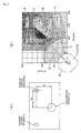
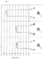
Figs. 6(a) and 6(b) are explanatory diagrams for illustrating operation of the embodiment of the present invention,Fig. 6(a) showing predetermined dimensions in a front view of a motorcycle having a single main lighting apparatus andFig. 6(b) showing a distribution of identification rates of the motorcycle according to the predetermined dimensions. -
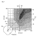
Fig. 7 is an explanatory diagram for illustrating a first definition example of auxiliary lighting apparatus disposition areas based onFig. 6(b) . -
Fig. 8 is an explanatory diagram for illustrating a second definition example of auxiliary lighting apparatus disposition areas based onFig. 6(b) . -
Fig. 9 is an explanatory diagram for illustrating a third definition example of auxiliary lighting apparatus disposition areas based onFig. 6(b) . -
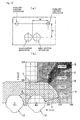
Figs. 10(a) and 10(b) are explanatory diagrams for illustrating operation of a fifth modified example of the embodiment of the present invention, corresponding toFigs. 6(a) and 6(b) ,Fig. 10(a) showing predetermined dimensions in a front view of a motorcycle having two main lighting apparatuses andFig. 10(b) showing a distribution of identification rates of the motorcycle according to the predetermined dimensions. -
Fig. 11 is a graph showing changes in the identification rate of the motorcycle when a light-emitting surface of the auxiliary lighting apparatus is varied. -
Fig. 12 is a graph showing changes in the identification rate of the motorcycle when the length of the light-emitting surface in the modified example shown inFig. 3 is varied. -
Fig. 13 is a graph showing changes in the identification rate of the motorcycle when the angle of the light-emitting surface in the modified example shown inFig. 3 is varied. -
Fig. 14 is a schematic view showing an experimental setup for measuring the identification rate. -
Fig. 15 is an explanatory drawing showing a typical perspective view pictured on the experimental setup. -
Fig. 16 is a graph showing changes in a glare width y relative to a luminous intensity x of the main lighting apparatus. - A specific embodiment to which the present invention is applied will be described below with reference to the accompanying drawings. Throughout the descriptions given hereunder, longitudinal, lateral, and other directions are the same as those in the vehicle unless otherwise specified.
-
Figs. 1 to 5 are front views (vehicle front views) showing amotorcycle 1 mounted with a vehicle lighting system according to an embodiment of the present invention as viewed from the front of the vehicle. The lighting system includes a single-bulb headlamp (hereinafter referred to as a "main lighting apparatus") 11 disposed at a center in a vehicle lateral direction to illuminate a vehicle forward area and left and right front flashers or hazard lamps (hereinafter referred to as flashing type lighting apparatuses) 15 disposed laterally sideways of themain lighting apparatus 11. The lighting system further includes steadily lighting type left and right position lamps (hereinafter referred to as auxiliary lighting apparatuses) 21 to 24 disposed upwardly of themain lighting apparatus 11 at left and right symmetrical positions. Of these, themain lighting apparatus 11 and theauxiliary lighting apparatuses 21 to 24 are disposed so as to make a vehicle front surface reminiscent of a "face," so that themotorcycle 1 is easily identifiable from an outside and conspicuity of themotorcycle 1 can thereby be enhanced. Specifically, the vehicle lighting system includes the pair of left and right auxiliary lighting apparatuses that are equivalent to "eyes" of the "face," of which the vehicle front face is reminiscent, and the single main lighting apparatus that is equivalent to a "mouth" of the "face." Themain lighting apparatus 11 and theauxiliary lighting apparatuses 21 to 24 light up steadily when a main switch of themotorcycle 1 is turned ON (or, for example, a lamp switch is further turned ON) and the flashingtype lighting apparatuses 15 flash off and on when the main switch of themotorcycle 1 is turned ON and, for example, a flasher switch or a hazard switch is turned ON. - Referring to
Figs. 1 through 5 ,reference numeral 3 denotes a head pipe disposed at a front end of a vehicle body frame, for steerably supporting a front wheel suspension system.Reference numeral 4 denotes a front wheel.Reference numeral 5 denotes a front fork having a lower end portion that journals thefront wheel 4.Reference numeral 6 denotes a handlebar for steering thefront wheel 4. Note here that each of the lighting apparatuses shown inFigs. 1 to 5 is mounted on, and rotatable with, the front wheel suspension system. At least one of these lighting apparatuses may instead be fixedly mounted on the vehicle body frame via, for example, a stay or a cowling. Further, the main lighting apparatus may be a dual-bulb type or a type having three or more bulbs including a plurality of light-emitting surfaces. - In addition, the main lighting apparatus 11 (headlamp) has a single lighting body in which a high beam lamp (driving headlamp) or a low beam lamp (meeting headlamp) is selected for use; however, the high beam lamp and the low beam lamp may instead be formed in respective individual lighting bodies. In addition, while the
main lighting apparatus 11 and theauxiliary lighting apparatuses 21 to 24 emit light of a similar color, such as, for example, white, the flashingtype lighting apparatuses 15 emit light of a color different from that of themain lighting apparatus 11 and theauxiliary lighting apparatuses 21 to 24, such as, for example, orange. - Disposition of each of the above-described lighting apparatuses will be described below.
- The low beam lamp of the
main lighting apparatus 11 according to the embodiment of the present invention has a luminous intensity equivalent to 750 [cd] (55 [W]) when the low beam lamp is turned ON. When themain lighting apparatus 11 with the low beam lamp turned ON is viewed from a vehicle forward direction, an area (glare area) G outside an outline OL of a main light-emittingsurface 11a, in which glare (a phenomenon in which an excessively bright local spot existing within a field of view makes an object to be viewed hard to view) tends more easily to occur, is defined by a width y as expressed inexpression 1 shown below when the luminous intensity of the main light-emittingsurface 11 a is x. Referring, for example, toFig. 6(b) , reference numeral H/L indicates a centroid (and the position of a light source (bulb), the center of a reflector, and a light-emitting center according to the embodiment of the present invention) of the main light-emittingsurface 11a of themain lighting apparatus 11.

-
Fig. 16 is a graph showing a relationship between the luminous intensity x [cd] of themain lighting apparatus 11 of a round-eye, single-bulb type laid off on the abscissa and the glare width y [mm] laid off on the ordinate. InFig. 16 , a curve CL represents approximate data obtained experimentally by the inventor and is expressed by theexpression 1. Further, inFig. 16 , reference numeral L5 is a line segment representing the luminous intensity x = 750 [cd] and reference numeral L6 is a line segment representing the glare width y = 155 [mm]. - Referring to
Figs. 1 ,6(a), and 6(b) , assume that, for example, light-emitting surfaces (auxiliary light-emitting surfaces) 21 L, 21 R of theauxiliary lighting apparatuses 21 are disposed within the glare area G outside themain lighting apparatus 11. This may cause an outline of the light-emitting surface of each lighting apparatus to blur, so that all of the light-emitting surfaces seem to be combined together to emit a single light. To make the vehicle front surface reminiscent of the "face" effectively, therefore, it is desirable that the light-emitting surfaces of the auxiliary lighting apparatuses be disposed outside the glare area G in the vehicle front view. - Referring to
Fig. 6(b) , "1.8 times" of area A means a ratio of an identification rate of themotorcycle 1 to be described later for a case in which the auxiliary lighting apparatus is disposed in area A and turned ON to the identification ratio of themotorcycle 1 for a case in which only themain lighting apparatus 11 is turned ON. Specifically, the identification rate of themotorcycle 1 having the auxiliary lighting apparatus in area A in addition to the main lighting apparatus is 1.8 times as much as the identification rate of themotorcycle 1 having only the main lighting apparatus. Similarly, if the auxiliary lighting apparatus is disposed in area B shown inFig. 6(b) , the identification rate is 2.0 times; if the auxiliary lighting apparatus is disposed in area C shown inFig. 6(b) , the identification rate is 2.2 times; and if the auxiliary lighting apparatus is disposed in area D shown inFig. 6(b) , the identification rate is 2.4 times. Note thatFigs. 6(b) and7 to 9 are graphs having W ofFig. 6(a) on the abscissa and D ofFig. 6(a) on the ordinate. Note also that, inFigs. 6(b) and7 to 9 , areas are shown only on the left-hand side of the vehicle; however, each of those areas is to exist also on the right-hand side of the vehicle; specifically, the areas are to exist symmetrically. In addition, the auxiliary lighting apparatus is to have a luminous intensity equivalent to 16 [cd] (equivalent to a 5-[W] incandescent lamp). The identification rates are distributed independently of the size of the glare area and the distribution remains the same regardless of whether the glare area is large or small as long as the auxiliary lighting apparatus is disposed outside the glare area. - Note here that the statement that "the auxiliary lighting apparatus is disposed in each area" means that at least part of the light-emitting surface of the auxiliary lighting apparatus exists in each area in the vehicle front view and, preferably, the bulb (light source, light-emitting center, centroid) of the auxiliary lighting apparatus exists in each area. If the auxiliary lighting apparatus has a plurality of light-emitting surfaces within each area, the centroid of each light-emitting surface is combined together with each other to serve as a centroid of the whole. Note also that the light-emitting surface includes a light source screen, such as a monitor screen.
- Referring to
Fig. 7 , an area H1, in which the auxiliary lighting apparatus is disposed, is set at a position that is, in the vehicle front view, upward of an upper end of the glare area G and laterally outside a left or right end of the glare area G. Then, disposing the light-emitting surface of the auxiliary lighting apparatus in the area H1 achieves an identification rate that is 2.0 times or more as much as the identification rate when themotorcycle 1 has only themain lighting apparatus 11. InFig. 7 , reference numeral L3 denotes a line segment indicating the upper end position of the glare area G and reference numeral L4 denotes a line segment indicating the left/right end position of the glare area G. The area H1 in which the auxiliary lighting apparatus is disposed is to be set within a range of 500 [mm] in a horizontal direction from the centroid H/L and 450 [mm] upward in a vertical direction therefrom. - Referring to
Fig. 8 , an area H2, in which the auxiliary lighting apparatus is disposed, is set, in the vehicle front view, within an area defined between a first inclined line L1 extending obliquely upwardly, at an angle of 35 degrees relative to a vertical line, from the centroid H/L of the main light-emittingsurface 11 a and a second inclined line L2 extending obliquely upwardly, at an angle of 55 degrees relative to the vertical line, from the centroid H/L, and outside an area 2G defined by awidth 2y outside the outline OL of the main light-emittingsurface 11 a. Disposing the light-emitting surface of the auxiliary lighting apparatus in the area H2 achieves an identification rate that is 2.2 times or more as much as the identification rate when themotorcycle 1 has only themain lighting apparatus 11. The area H2 in which the auxiliary lighting apparatus is disposed is to be set within a range of 500 [mm] in the horizontal direction from the centroid H/L and 450 [mm] upward in the vertical direction therefrom. - Further, referring to
Fig. 9 , an area (which substantially corresponds to the above-mentioned area D) surrounded by line segments specified by coordinates as detailed below when the centroid H/L of the main light-emittingsurface 11 a in the vehicle front view is defined as an origin and D [mm] is the ordinate and W [mm] is the abscissa, is set as an area H3 in which the auxiliary lighting apparatus is disposed. Then, disposing the auxiliary lighting apparatus in the area H3 achieves an identification rate that is substantially 2.4 times as much as the identification rate when themotorcycle 1 has only themain lighting apparatus 11. - (1) A first line segment that passes through (W335, D450) and (W250, D310)
- (2) A second line segment that passes through (W250, D310) and (W238, D224)
- (3) A third line segment that passes through (W238, D224) and (W252, D210)
- (4) A fourth line segment that passes through (W252, D210) and (W267, D224)
- (5) A fifth line segment that passes through (W267, D224) and (W367, D342)
- (6) A sixth line segment that passes through (W367, D342) and (W500, D390)
- (7) A seventh line segment specified by D = 450
- (8) An eighth line segment specified by W = 500
- The lighting system shown in
Fig. 1 typically includes theauxiliary lighting apparatuses 21 having the light-emittingsurfaces Fig. 1 , reference numeral BL denotes a bulb (light source) of theauxiliary lighting apparatus 21. - The lighting system shown in
Fig. 2 , on the other hand, typically includes theauxiliary lighting apparatuses 22 having light-emittingsurfaces Fig. 2 , reference numeral C denotes a center of each of the auxiliary light-emittingsurface - A graph shown in
Fig. 11 shows, in sequence from the left to the right, the identification rate of the motorcycle having theauxiliary lighting apparatuses 21 that have the rectangular light-emittingsurfaces surfaces auxiliary lighting apparatuses 22 that have the annular light-emittingsurfaces - The
auxiliary lighting apparatus 21 shown inFig. 11 is disposed such that a light source having a luminous intensity equivalent to 16 [cd] (equivalent to a 5-[W] incandescent lamp) is disposed at a position of 250 [mm] in the horizontal direction and 250 [mm] upward in the vertical direction from the centroid H/L. Similarly, the auxiliary lighting apparatus 21' is disposed such that a light source having a luminous intensity equivalent to 16 [cd] is disposed additionally laterally outside the light source of theauxiliary lighting apparatuses 21. Theauxiliary lighting apparatus 22 is disposed such that the position of the light source of theauxiliary lighting apparatuses 21 is disposed at a center of the annular shape (the luminous intensity is equivalent to that of the auxiliary lighting apparatuses 21). - Specifically, it is known that, when the auxiliary lighting apparatuses have the annular light-emitting surfaces, the light-emitting surfaces are enhanced as the "eyes" of the "face" of which the motorcycle front face is reminiscent, so that the identification rate, specifically, the conspicuity of the motorcycle can be further enhanced. The annular light-emitting surface has an inside diameter of at least 80 [mm]. The rectangular light-emitting surface has approximate dimensions of 55 [mm] in height by 75 [mm] in width.
-
Fig. 3 shows an example, in which theauxiliary lighting apparatuses 23 are disposed on front surfaces of stays of left and right rearview mirrors M so as to be inclined in the vehicle front view to follow along the front surfaces. Theauxiliary lighting apparatuses 23 have light-emittingsurfaces surfaces surfaces -
Fig. 12 shows results of measurements taken of the identification rate of the motorcycle by varying the length L of the line segment shape with the angle θ of the light-emitting surface of theauxiliary lighting apparatus 23 set at 60 degrees.Fig. 12 tells that, while the identification rate is maintained at relatively high values when the length L is 150 [mm] or more, there is a significant reduction in the identification rate when the length L becomes less than 150 [mm]. Note that, if part of the line segment shape overlaps the glare area G, the length L is a length of a portion not overlapping the glare area G. -
Fig. 13 shows results of measurements taken of the identification rate of the motorcycle by varying the angle θ of the line segment shape with the length L of the light-emitting surface of theauxiliary lighting apparatus 23 set at 150 [mm].Fig. 13 tells that, while the identification rate is maintained at relatively high values when the angle θ falls within a range of 0 to 60 degrees, there is a significant reduction in the identification rate when the angle θ exceeds 60 degrees. - Referring to
Fig. 4 , light-emitting surfaces of the annular shape and light-emitting surfaces of the oblique line segment shape may be appropriately combined to form theauxiliary lighting apparatuses 24 having light-emittingsurfaces - Referring further to
Fig. 5 , another possible arrangement includes anauxiliary lighting apparatus 25 separately disposed at a portion equivalent to a "nose" in the "face." Theauxiliary lighting apparatus 25 has a luminous intensity lower than that of the main lighting apparatus that is equivalent to the "mouth" of the "face" of which the motorcycle front face including those lighting apparatuses is reminiscent. - Referring to
Figs. 10(a) and 10(b) , the motorcycle may include a dual-bulb main lighting apparatus 12 (having a plurality of light-emitting surfaces 12a). In this arrangement, a centroid H/L' of the entiremain lighting apparatus 12 is each of centroids H/L of the light-emitting surfaces combined together (inFig. 10(b) , the center between the centroids H/L of the light-emitting surfaces). A glare area G' defined by a width y outside an outline OL of each light-emitting surface is greater than the glare area G of themain lighting apparatus 11 of the single-bulb type. The glare area G' overlaps part of each of the above-described areas to shave off the part, thereby making smaller the areas. - An experimental setup measuring the identification rate of the
motorcycle 1 will be described below. - An
experimental setup 100 shown inFig. 14 includes adisplay 101, apersonal computer 102, asteering wheel 103, aseat 104, andresponse buttons steering wheel 103 and theseat 104 simulate those on passenger vehicles. An observer (subject) P is seated in theseat 104 with his/her hands holding onto thesteering wheel 103 and observes thedisplay 101 ahead of him/her. Thedisplay 101 shows a computer graphics image (perspective view) processed by thepersonal computer 102. The observer P is to respond whether themotorcycle 1 exists within the image. Theresponse buttons steering wheel 103. The observer P is to press theresponse button 105A if he/she confirms presence of themotorcycle 1 within the image and theresponse button 105B if he/she does not confirm presence of themotorcycle 1 within the image. - An operation of each of the
response buttons personal computer 102 and whether or not the observer P could identify themotorcycle 1 within the image shown on thedisplay 101 is recorded. Thepersonal computer 102 stores therein a plurality of perspective views of a typical traffic intersection scene generated through computer graphics. Each of these perspective views of a typical traffic intersection scene is unique, different from the others in terms of background images and placement of vehicles. For each of these perspective views of a typical traffic intersection scene, three different kinds of images are provided: one including asingle motorcycle 1 having a single-bulb main lighting apparatus, one including asingle motorcycle 1 mounted with the above-described lighting system of the embodiment of the present invention, and the other including nomotorcycle 1. - The
display 101 randomly shows each of the three different kinds of perspective views at 0.5-sec. intervals. After the image is presented, the observer P responds using theresponse buttons motorcycle 1 or not. The ratio of the number of images in which the observer P confirmed the presence of themotorcycle 1 to the number of images presented containing themotorcycle 1 is then recorded as the identification rate of themotorcycle 1 in each of the images. - Each of above-cited graphs is based on the results obtained from the above experiment. The "ratio" shown in each graph represents the quotient of the identification rate of the
motorcycle 1 mounted with the above-described lighting system divided by the identification rate of themotorcycle 1 having the single-bulbmain lighting apparatus 11. -
Fig. 15 shows a typical perspective view of a traffic intersection scene used in the experiment. The image shows a nighttime traffic intersection scene with the motorcycle in the image being displayed as existing at a distance of 80 m from the observer P. The upper image ofFig. 15 is a perspective view of the typical traffic intersection scene and the lower image ofFig. 15 is an enlarged view of a portion showing the motorcycle in the image. - As described heretofore, the vehicle lighting system according to the embodiment of the present invention has the
main lighting apparatus 11 including the main light-emittingsurface 11 a that illuminates the vehicle forward area and flashingtype lighting apparatuses 15 disposed laterally sideways at right and left of themain lighting apparatus 11 in the vehicle front view. In this vehicle lighting system, the glare area G with the width y as expressed inexpression 1 when themain lighting apparatus 11 has a luminous intensity of x is defined outside the outline OL of the main light-emittingsurface 11 a in the vehicle front view. Further, the auxiliary lighting apparatus disposition area H1 to H3, in which theauxiliary lighting apparatus 21 to 24 of the steadily lighting type different from the flashingtype lighting apparatuses 15 is disposed, is set upwardly of themain lighting apparatus 11 and outside the glare area G. - In accordance with foregoing arrangements, the vehicle front surface is made to be readily reminiscent of a "face," having the
main lighting apparatus 11 as a "mouth" and theauxiliary lighting apparatuses 21 to 24 as "eyes," so that conspicuity of the vehicle can be easily enhanced. - The
auxiliary lighting apparatuses 21 to 24, being disposed outside the glare area G of themain lighting apparatus 11, help inhibit the outline of the light-emitting surface of each lighting apparatus from blurring to be fused. The vehicle front surface can therefore be readily reminiscent of a "face," so that the conspicuity of the vehicle can be easily enhanced. The steadily lighting typeauxiliary lighting apparatuses 21 to 24 are provided in addition to the flashingtype lighting apparatuses 15. This results in the "mouth" and the "eyes" being steadily lit up, which helps make the vehicle front surface reminiscent of a "face." - In the vehicle lighting system according to the embodiment of the present invention, the auxiliary lighting apparatus disposition area H1 is set at the position that is, in the vehicle front view, upward of the upper end of the glare area G and laterally outside the left or right ends of the glare area G. Accordingly, the
auxiliary lighting apparatuses 21 to 24 are disposed upwardly of the glare area G of themain lighting apparatus 11 and laterally outside the left and right ends of the glare area G apart from each other. In addition, theauxiliary lighting apparatuses 21 to 24 are disposed at appropriate positions equivalent to the "eyes" of the "face," of which the vehicle front face is reminiscent. This makes the vehicle front surface readily reminiscent of the "face," so that the conspicuity of the vehicle can be easily enhanced. - In the vehicle lighting system according to the embodiment of the present invention, the auxiliary lighting apparatus disposition area H2 is set, in the vehicle front view, within the area defined between the first inclined line L1 extending obliquely upwardly at an angle of 35 degrees relative to the vertical line from the centroid H/L of the main light-emitting
surface 11 a and the second inclined line L2 extending obliquely upwardly at an angle of 55 degrees relative to the vertical line from the centroid H/L, and outside the area defined by thewidth 2y outside the outline OL of the main light-emittingsurface 11 a. Similarly as above, the foregoing arrangements make the vehicle front surface readily reminiscent of the "face," so that the conspicuity of the vehicle can be easily enhanced. - In the vehicle lighting system according to the embodiment of the present invention, the auxiliary lighting apparatus disposition area H3 is the area surrounded by the above-referenced line segments when the centroid H/L of the main light-emitting
surface 11a in the vehicle front view is defined as the origin and W [mm] is the abscissa and D [mm] is the ordinate. Theauxiliary lighting apparatuses 21 to 24 are disposed even further apart from the glare area G of themain lighting apparatus 11. In addition, theauxiliary lighting apparatuses 21 to 24 are disposed at even more appropriate positions equivalent to the "eyes" of the "face," of which the vehicle front face is reminiscent. The conspicuity of the vehicle can therefore be even more easily enhanced. - In the vehicle lighting system according to the embodiment of the present invention, if the light source of the auxiliary lighting apparatus is disposed in the auxiliary lighting apparatus disposition area, the contrast with surrounding areas, because of the light source of the auxiliary lighting apparatus emitting an even more intense light, is more readily reminiscent of the black part of the "eye." This makes the vehicle front surface readily reminiscent of the "face" effectively.
- In the vehicle lighting system according to the embodiment of the present invention, the
auxiliary lighting apparatus 22 emits light in the annular shape in the vehicle front view. If the center of the annular shape is disposed in the auxiliary lighting apparatus disposition area, the contrast, which is produced because the center of the annular shape emits light less intense than that emitted by the light-emitting surface of the annular shape, is more readily reminiscent of the black part of the "eye," which makes the vehicle front surface readily reminiscent of the "face" effectively. - In the vehicle lighting system according to the embodiment of the present invention, the
auxiliary lighting apparatus 23 emits light in the line segment shape inclined so as to be disposed more upwardly at outer sides in the vehicle width direction in the vehicle front view. Preferably, the auxiliary lighting apparatus is disposed at an angle of 0 to 60 degrees relative to the vertical line and has at least a length of 150 [mm]. Based on the fact that human beings recognize more easily an oblique component as compared with vertical and horizontal components, theauxiliary lighting apparatus 23 is arranged to emit light in an oblique line segment shape and have an adequate length. These arrangements help make the "eye" more easily recognizable. This makes the vehicle front surface readily reminiscent of the "face," so that the conspicuity of the vehicle can be easily enhanced. - In the vehicle lighting system according to the embodiment of the present invention, the
main lighting apparatus 11 and the flashingtype lighting apparatus 15 emit light of different colors from each other and theauxiliary lighting apparatuses 21 to 24 emit light of a similar color as that of the light emitted by themain lighting apparatus 11. Accordingly, themain lighting apparatus 11 and theauxiliary lighting apparatuses 21 to 24 are made to emit light of a color different from that of the flasher or other flashingtype lighting apparatus 15. This helps make the vehicle front surface readily reminiscent of the "face," having themain lighting apparatus 11 as a "mouth" and theauxiliary lighting apparatuses 21 to 24 as "eyes," regardless of whether the flashingtype lighting apparatus 15 is turned ON, so that conspicuity of the vehicle can be easily enhanced. - In the vehicle lighting system according to the embodiment of the present invention, the
auxiliary lighting apparatuses 21 to 24 are disposed symmetrically about themain lighting apparatus 11. Theauxiliary lighting apparatuses 21 to 24 as the "eyes" are disposed symmetrically about themain lighting apparatus 11 as the "mouth." This makes the vehicle front surface even more readily reminiscent of the "face." - In the vehicle lighting system according to the embodiment of the present invention, the
main lighting apparatus 11 includes the low beam lamp illuminating a relatively nearby area and the high beam lamp illuminating a remote area relative to the area illuminated by the low beam lamp. The auxiliary lighting apparatus disposition area H1 to H3 is set corresponding to the glare area when the low beam lamp is turned ON. This makes the vehicle front surface reminiscent of the "face" even when the low beam lamp, which is less noticeable when the high beam lamp is turned ON, is turned ON. Conspicuity of the vehicle can therefore be enhanced. - The present invention is not limited to the above-described embodiment and is applicable, for example, to a three-wheeled or a four-wheeled vehicle, in addition to the
motorcycle 1. - The high beam lamp and the low beam lamp may be formed in respective individual lighting bodies and the main lighting apparatus may be the low beam lamp. This allows the high beam lamp to be disposed without regard to the positions of the
auxiliary lighting apparatuses 21 to 24, which easily enhances the degree of freedom in disposing the high beam lamp. - While the present invention has been described with reference to the preferred embodiment, it will be understood by those skilled in the art that various changes in form and detail may be made therein without departing from the spirit and scope of the invention.
- The invention is directed to inhibit, in a vehicle lighting system having a plurality of lighting apparatuses disposed so as to make a vehicle front surface reminiscent of a "face," an outline of a light-emitting surface of each of the lighting apparatuses from blurring to be fused.
- A glare area G with a width y as expressed in an expression "y = a + b·In(x) (In is a natural logarithm)," "a = -107," and "b = 39.6" when a main lighting apparatus has a luminous intensity of x is defined outside an outline OL of a main light-emitting surface in a vehicle front view, and an auxiliary lighting apparatus disposition area, in which an auxiliary lighting apparatus of a steadily lighting type different from a flashing type lighting apparatus is disposed, is set upwardly of the main lighting apparatus and outside the glare area G.
Claims (11)
- A vehicle lighting system having a main lighting apparatus (11) including a main light-emitting surface (11 a) that illuminates a vehicle forward area and flashing type lighting apparatuses (15) disposed laterally sideways at right and left of the main lighting apparatus (11) in a vehicle front view, wherein:a glare area (G) with a width y as expressed in an expression given below when the main lighting apparatus (11) has a luminous intensity of x is defined outside an outline (OL) of the main light-emitting surface (11 a) in the vehicle front view; andan auxiliary lighting apparatus (H1 to H3) disposition area, in which an auxiliary lighting apparatus (21 to 24) of a steadily lighting type different from the flashing type lighting apparatuses (15) is disposed, is set upwardly of the main lighting apparatus (11) and outside the glare area (G).

b = 39.6 - The vehicle lighting system according to claim 1, wherein
the auxiliary lighting apparatus disposition area (H1 to H3) is set at a position that is, in the vehicle front view, upward of an upper end of the glare area (G) and laterally outside a left or right end of the glare area (G). - The vehicle lighting system according to claim 1, wherein
the auxiliary lighting apparatus disposition area (H1 to H3) is set, in the vehicle front view, within an area defined between a first inclined line extending obliquely upwardly at an angle of 35 degrees relative to a vertical line from a centroid (H/L) of the main light-emitting surface (11 a) and a second inclined line extending obliquely upwardly at an angle of 55 degrees relative to the vertical line from the centroid (H/L), and outside an area defined by a width 2y outside the outline (OL) of the main light-emitting surface (11 a). - The vehicle lighting system according to claim 1, wherein
the auxiliary lighting apparatus disposition area (H1 to H3) is an area surrounded by line segments specified by coordinates as detailed below when the centroid (H/L) of the main light-emitting surface (11a) in the vehicle front view is defined as an origin and W [mm] is an abscissa and D [mm] is an ordinate.(1) A first line segment that passes through (W335, D450) and (W250, D310)(2) A second line segment that passes through (W250, D310) and (W238, D224)(3) A third line segment that passes through (W238, D224) and (W252, D210)(4) A fourth line segment that passes through (W252, D210) and (W267, D224)(5) A fifth line segment that passes through (W267, D224) and (W367, D342)(6) A sixth line segment that passes through (W367, D342) and (W500, D390)(7) A seventh line segment specified by D = 450(8) An eighth line segment specified by W = 500 - The vehicle lighting system according to any one of claims 1 to 4, wherein
the auxiliary lighting apparatus (21 to 24) has a light source disposed in the auxiliary lighting apparatus disposition area (H1 to H3). - The vehicle lighting system according to any one of claims 1 to 4, wherein
the auxiliary lighting apparatus (21 to 24) emits light in an annular shape in the vehicle front view and a center of the annular shape is disposed in the auxiliary lighting apparatus disposition area (H1 to H3). - The vehicle lighting system according to any one of claims 1 to 4, wherein
the auxiliary lighting apparatus (21 to 24) emits light in a line segment shape inclined so as to be disposed more upwardly at outer sides in a vehicle width direction in the vehicle front view, the auxiliary lighting apparatus (21 to 24) being disposed at an angle of 0 to 60 degrees relative to a vertical line and having at least a length of 150 [mm]. - The vehicle lighting system according to any one of claims 1 to 7, wherein
the main lighting apparatus (11) and the flashing type lighting apparatus (15) emit light of different colors from each other and the auxiliary lighting apparatus (21 to 24) emits light of a similar color as that of the light emitted by the main lighting apparatus (11). - The vehicle lighting system according to any one of claims 1 to 8, wherein
the auxiliary lighting apparatuses (21 to 24) are disposed symmetrically about the main lighting apparatus (11). - The vehicle lighting system according to any one of claims 1 to 9, wherein
the vehicle includes a low beam lamp illuminating a relatively nearby area and a high beam lamp illuminating a remote area relative to the area illuminated by the low beam lamp and the main lighting apparatus (11) is the low beam lamp. - The vehicle lighting system according to any one of claims 1 to 9, wherein
the main lighting apparatus (11) includes a low beam lamp illuminating a relatively nearby area and a high beam lamp illuminating a remote area relative to the area illuminated by the low beam lamp and the auxiliary lighting apparatus disposition area (H1 to H3) is set corresponding to the glare area (G) when the low beam lamp is turned ON.
Applications Claiming Priority (2)
| Application Number | Priority Date | Filing Date | Title |
|---|---|---|---|
| JP2009018634 | 2009-01-29 | ||
| JP2009120262A JP5264615B2 (en) | 2009-01-29 | 2009-05-18 | Vehicle lighting system |
Publications (2)
| Publication Number | Publication Date |
|---|---|
| EP2213511A1 true EP2213511A1 (en) | 2010-08-04 |
| EP2213511B1 EP2213511B1 (en) | 2013-08-21 |
Family
ID=41800707
Family Applications (1)
| Application Number | Title | Priority Date | Filing Date |
|---|---|---|---|
| EP09176758.2A Active EP2213511B1 (en) | 2009-01-29 | 2009-11-23 | Vehicle lighting system |
Country Status (5)
| Country | Link |
|---|---|
| US (1) | US8297812B2 (en) |
| EP (1) | EP2213511B1 (en) |
| JP (1) | JP5264615B2 (en) |
| CN (1) | CN101850803B (en) |
| CA (1) | CA2686220C (en) |
Cited By (1)
| Publication number | Priority date | Publication date | Assignee | Title |
|---|---|---|---|---|
| EP2669161A1 (en) * | 2012-05-31 | 2013-12-04 | Yamaha Hatsudoki Kabushiki Kaisha | Sub headlight unit for use in vehicle that leans into turns |
Families Citing this family (5)
| Publication number | Priority date | Publication date | Assignee | Title |
|---|---|---|---|---|
| US10023103B2 (en) | 2013-09-13 | 2018-07-17 | J.W. Speaker, Corporation | Systems and methods for illumination control and distribution during a vehicle bank |
| JP6176859B2 (en) * | 2015-07-15 | 2017-08-09 | 本田技研工業株式会社 | Turn signal structure of vehicle |
| JP6839119B2 (en) * | 2018-02-19 | 2021-03-03 | 本田技研工業株式会社 | Saddle-type vehicle |
| DE102020101252A1 (en) * | 2020-01-21 | 2021-07-22 | Bayerische Motoren Werke Aktiengesellschaft | Rearview mirror for a single-track motor vehicle |
| TWI891284B (en) * | 2024-03-15 | 2025-07-21 | 邑昇實業股份有限公司 | Bicycle Turn Signal System |
Citations (9)
| Publication number | Priority date | Publication date | Assignee | Title |
|---|---|---|---|---|
| JP2001334976A (en) * | 2000-05-24 | 2001-12-04 | Kawasaki Heavy Ind Ltd | Lamp for visual recognition of motorcycles |
| EP1473215A1 (en) * | 2002-02-05 | 2004-11-03 | Honda Giken Kogyo Kabushiki Kaisha | Lamp system for motorcycles |
| US20060056191A1 (en) * | 2004-09-10 | 2006-03-16 | Kiyotaka Uemura | Vehicle |
| JP2006298045A (en) | 2005-04-18 | 2006-11-02 | Honda Motor Co Ltd | Vehicle lighting system |
| EP1767398A1 (en) * | 2005-09-26 | 2007-03-28 | HONDA MOTOR CO., Ltd. | Vehicular lighting unit and vehicle with enhanced perceived accuracy |
| EP1859995A2 (en) * | 2006-05-23 | 2007-11-28 | Schefenacker Patents S.à.r.l. | Exterior vehicle mirror |
| EP1903273A1 (en) * | 2006-09-19 | 2008-03-26 | Peugeot Citroen Automobiles S.A. | Dual function automobile headlamp |
| US20080186723A1 (en) * | 2007-02-05 | 2008-08-07 | Chi-San Huang | Two-sided light-passing device for the additional warning light of an automobile rear-view mirror |
| DE102007010747A1 (en) * | 2007-02-27 | 2008-08-28 | Schefenacker Patents S.à.r.l. | Exterior rearview mirror for vehicles, particularly for motor vehicles, has mirror housing, whose wall has opening and light opening of illuminating unit lies in opening |
Family Cites Families (10)
| Publication number | Priority date | Publication date | Assignee | Title |
|---|---|---|---|---|
| JPS5334687Y2 (en) * | 1975-09-30 | 1978-08-25 | ||
| JPH0223289U (en) * | 1988-08-01 | 1990-02-15 | ||
| EP0473978B1 (en) * | 1990-08-15 | 1994-11-02 | Honda Giken Kogyo Kabushiki Kaisha | Two-wheeled vehicle control apparatus |
| DE10118687A1 (en) * | 2001-04-14 | 2002-10-17 | Bayerische Motoren Werke Ag | Motor vehicle headlamp arrangement has linear light unit in form of tubular gas discharge lamp controlled by voltage adapter that controls ignition voltage independently of temperature |
| JP4001731B2 (en) * | 2001-09-17 | 2007-10-31 | 本田技研工業株式会社 | License light peripheral structure |
| JP3092552U (en) * | 2002-09-03 | 2003-03-20 | 株式会社キジマ | Motorcycle lamp |
| JP4086227B2 (en) * | 2002-12-09 | 2008-05-14 | 本田技研工業株式会社 | Rearview mirror device |
| JP4508971B2 (en) * | 2005-07-28 | 2010-07-21 | 本田技研工業株式会社 | Lighting device |
| US7588356B2 (en) * | 2007-02-28 | 2009-09-15 | Yamaha Hatsudoki Kabushiki Kaisha | Structure of tail light for motorcycle |
| US8016462B2 (en) * | 2009-02-02 | 2011-09-13 | Kuryakyn Holdings, LLC | Motorcycle adjustable light bar assembly |
-
2009
- 2009-05-18 JP JP2009120262A patent/JP5264615B2/en not_active Expired - Fee Related
- 2009-11-20 CA CA2686220A patent/CA2686220C/en not_active Expired - Fee Related
- 2009-11-23 EP EP09176758.2A patent/EP2213511B1/en active Active
-
2010
- 2010-01-06 CN CN201010001441.5A patent/CN101850803B/en not_active Expired - Fee Related
- 2010-01-27 US US12/694,646 patent/US8297812B2/en not_active Expired - Fee Related
Patent Citations (9)
| Publication number | Priority date | Publication date | Assignee | Title |
|---|---|---|---|---|
| JP2001334976A (en) * | 2000-05-24 | 2001-12-04 | Kawasaki Heavy Ind Ltd | Lamp for visual recognition of motorcycles |
| EP1473215A1 (en) * | 2002-02-05 | 2004-11-03 | Honda Giken Kogyo Kabushiki Kaisha | Lamp system for motorcycles |
| US20060056191A1 (en) * | 2004-09-10 | 2006-03-16 | Kiyotaka Uemura | Vehicle |
| JP2006298045A (en) | 2005-04-18 | 2006-11-02 | Honda Motor Co Ltd | Vehicle lighting system |
| EP1767398A1 (en) * | 2005-09-26 | 2007-03-28 | HONDA MOTOR CO., Ltd. | Vehicular lighting unit and vehicle with enhanced perceived accuracy |
| EP1859995A2 (en) * | 2006-05-23 | 2007-11-28 | Schefenacker Patents S.à.r.l. | Exterior vehicle mirror |
| EP1903273A1 (en) * | 2006-09-19 | 2008-03-26 | Peugeot Citroen Automobiles S.A. | Dual function automobile headlamp |
| US20080186723A1 (en) * | 2007-02-05 | 2008-08-07 | Chi-San Huang | Two-sided light-passing device for the additional warning light of an automobile rear-view mirror |
| DE102007010747A1 (en) * | 2007-02-27 | 2008-08-28 | Schefenacker Patents S.à.r.l. | Exterior rearview mirror for vehicles, particularly for motor vehicles, has mirror housing, whose wall has opening and light opening of illuminating unit lies in opening |
Cited By (1)
| Publication number | Priority date | Publication date | Assignee | Title |
|---|---|---|---|---|
| EP2669161A1 (en) * | 2012-05-31 | 2013-12-04 | Yamaha Hatsudoki Kabushiki Kaisha | Sub headlight unit for use in vehicle that leans into turns |
Also Published As
| Publication number | Publication date |
|---|---|
| CN101850803B (en) | 2015-02-18 |
| JP2010195380A (en) | 2010-09-09 |
| JP5264615B2 (en) | 2013-08-14 |
| EP2213511B1 (en) | 2013-08-21 |
| US8297812B2 (en) | 2012-10-30 |
| US20100195340A1 (en) | 2010-08-05 |
| CA2686220C (en) | 2013-03-19 |
| CA2686220A1 (en) | 2010-07-29 |
| CN101850803A (en) | 2010-10-06 |
Similar Documents
| Publication | Publication Date | Title |
|---|---|---|
| US10741083B2 (en) | Road surface image-drawing system for vehicle | |
| EP2213511B1 (en) | Vehicle lighting system | |
| CN100429557C (en) | Head-up display device for two-wheeled motorcycles | |
| CN111556839B (en) | Saddle-ride type vehicle | |
| JP4843517B2 (en) | Visual assist device for vehicles | |
| US7187270B2 (en) | Vehicle display device and light guide plate thereof | |
| KR20150095580A (en) | Driving support apparatus for vehicle | |
| KR101852375B1 (en) | Lamp apparatus for Vehicles | |
| JP6262111B2 (en) | Vehicle display device | |
| CN114401867A (en) | Drawing device for vehicle | |
| US10315556B2 (en) | Information providing apparatus | |
| CN110997407A (en) | autonomous vehicle | |
| EP1473215B1 (en) | Lamp system for motorcycles | |
| JP4430599B2 (en) | Vehicle lighting unit and automobile with improved perception accuracy | |
| EP4488150A1 (en) | Bicycle lighting device | |
| JP2002063803A (en) | Method of road illumination and eye-guiding illumination device | |
| JP2017084748A (en) | Self-luminous body-attachable belt | |
| JP2020185997A (en) | Vehicular display system | |
| JP7306328B2 (en) | Driving support device | |
| JP4412664B2 (en) | Vehicle recognition device | |
| JP2023037106A (en) | Vehicular information presentation device | |
| WO2023199884A1 (en) | Vehicle lamp | |
| JP2014083963A (en) | Bicycle | |
| JP2017114486A (en) | Vehicle display device |
Legal Events
| Date | Code | Title | Description |
|---|---|---|---|
| PUAI | Public reference made under article 153(3) epc to a published international application that has entered the european phase |
Free format text: ORIGINAL CODE: 0009012 |
|
| 17P | Request for examination filed |
Effective date: 20091123 |
|
| AK | Designated contracting states |
Kind code of ref document: A1 Designated state(s): AT BE BG CH CY CZ DE DK EE ES FI FR GB GR HR HU IE IS IT LI LT LU LV MC MK MT NL NO PL PT RO SE SI SK SM TR |
|
| GRAP | Despatch of communication of intention to grant a patent |
Free format text: ORIGINAL CODE: EPIDOSNIGR1 |
|
| GRAS | Grant fee paid |
Free format text: ORIGINAL CODE: EPIDOSNIGR3 |
|
| GRAA | (expected) grant |
Free format text: ORIGINAL CODE: 0009210 |
|
| AK | Designated contracting states |
Kind code of ref document: B1 Designated state(s): AT BE BG CH CY CZ DE DK EE ES FI FR GB GR HR HU IE IS IT LI LT LU LV MC MK MT NL NO PL PT RO SE SI SK SM TR |
|
| REG | Reference to a national code |
Ref country code: GB Ref legal event code: FG4D |
|
| REG | Reference to a national code |
Ref country code: CH Ref legal event code: EP |
|
| REG | Reference to a national code |
Ref country code: AT Ref legal event code: REF Ref document number: 627842 Country of ref document: AT Kind code of ref document: T Effective date: 20130915 |
|
| REG | Reference to a national code |
Ref country code: IE Ref legal event code: FG4D |
|
| REG | Reference to a national code |
Ref country code: DE Ref legal event code: R096 Ref document number: 602009018143 Country of ref document: DE Effective date: 20131017 |
|
| REG | Reference to a national code |
Ref country code: NL Ref legal event code: VDEP Effective date: 20130821 Ref country code: AT Ref legal event code: MK05 Ref document number: 627842 Country of ref document: AT Kind code of ref document: T Effective date: 20130821 |
|
| REG | Reference to a national code |
Ref country code: LT Ref legal event code: MG4D |
|
| PG25 | Lapsed in a contracting state [announced via postgrant information from national office to epo] |
Ref country code: NO Free format text: LAPSE BECAUSE OF FAILURE TO SUBMIT A TRANSLATION OF THE DESCRIPTION OR TO PAY THE FEE WITHIN THE PRESCRIBED TIME-LIMIT Effective date: 20131121 Ref country code: LT Free format text: LAPSE BECAUSE OF FAILURE TO SUBMIT A TRANSLATION OF THE DESCRIPTION OR TO PAY THE FEE WITHIN THE PRESCRIBED TIME-LIMIT Effective date: 20130821 Ref country code: HR Free format text: LAPSE BECAUSE OF FAILURE TO SUBMIT A TRANSLATION OF THE DESCRIPTION OR TO PAY THE FEE WITHIN THE PRESCRIBED TIME-LIMIT Effective date: 20130821 Ref country code: PT Free format text: LAPSE BECAUSE OF FAILURE TO SUBMIT A TRANSLATION OF THE DESCRIPTION OR TO PAY THE FEE WITHIN THE PRESCRIBED TIME-LIMIT Effective date: 20131223 Ref country code: AT Free format text: LAPSE BECAUSE OF FAILURE TO SUBMIT A TRANSLATION OF THE DESCRIPTION OR TO PAY THE FEE WITHIN THE PRESCRIBED TIME-LIMIT Effective date: 20130821 Ref country code: IS Free format text: LAPSE BECAUSE OF FAILURE TO SUBMIT A TRANSLATION OF THE DESCRIPTION OR TO PAY THE FEE WITHIN THE PRESCRIBED TIME-LIMIT Effective date: 20131221 Ref country code: CY Free format text: LAPSE BECAUSE OF FAILURE TO SUBMIT A TRANSLATION OF THE DESCRIPTION OR TO PAY THE FEE WITHIN THE PRESCRIBED TIME-LIMIT Effective date: 20130904 Ref country code: SE Free format text: LAPSE BECAUSE OF FAILURE TO SUBMIT A TRANSLATION OF THE DESCRIPTION OR TO PAY THE FEE WITHIN THE PRESCRIBED TIME-LIMIT Effective date: 20130821 |
|
| PG25 | Lapsed in a contracting state [announced via postgrant information from national office to epo] |
Ref country code: FI Free format text: LAPSE BECAUSE OF FAILURE TO SUBMIT A TRANSLATION OF THE DESCRIPTION OR TO PAY THE FEE WITHIN THE PRESCRIBED TIME-LIMIT Effective date: 20130821 Ref country code: PL Free format text: LAPSE BECAUSE OF FAILURE TO SUBMIT A TRANSLATION OF THE DESCRIPTION OR TO PAY THE FEE WITHIN THE PRESCRIBED TIME-LIMIT Effective date: 20130821 Ref country code: LV Free format text: LAPSE BECAUSE OF FAILURE TO SUBMIT A TRANSLATION OF THE DESCRIPTION OR TO PAY THE FEE WITHIN THE PRESCRIBED TIME-LIMIT Effective date: 20130821 Ref country code: GR Free format text: LAPSE BECAUSE OF FAILURE TO SUBMIT A TRANSLATION OF THE DESCRIPTION OR TO PAY THE FEE WITHIN THE PRESCRIBED TIME-LIMIT Effective date: 20131122 Ref country code: BE Free format text: LAPSE BECAUSE OF FAILURE TO SUBMIT A TRANSLATION OF THE DESCRIPTION OR TO PAY THE FEE WITHIN THE PRESCRIBED TIME-LIMIT Effective date: 20130821 Ref country code: SI Free format text: LAPSE BECAUSE OF FAILURE TO SUBMIT A TRANSLATION OF THE DESCRIPTION OR TO PAY THE FEE WITHIN THE PRESCRIBED TIME-LIMIT Effective date: 20130821 |
|
| PG25 | Lapsed in a contracting state [announced via postgrant information from national office to epo] |
Ref country code: CY Free format text: LAPSE BECAUSE OF FAILURE TO SUBMIT A TRANSLATION OF THE DESCRIPTION OR TO PAY THE FEE WITHIN THE PRESCRIBED TIME-LIMIT Effective date: 20130821 |
|
| PG25 | Lapsed in a contracting state [announced via postgrant information from national office to epo] |
Ref country code: DK Free format text: LAPSE BECAUSE OF FAILURE TO SUBMIT A TRANSLATION OF THE DESCRIPTION OR TO PAY THE FEE WITHIN THE PRESCRIBED TIME-LIMIT Effective date: 20130821 Ref country code: SK Free format text: LAPSE BECAUSE OF FAILURE TO SUBMIT A TRANSLATION OF THE DESCRIPTION OR TO PAY THE FEE WITHIN THE PRESCRIBED TIME-LIMIT Effective date: 20130821 Ref country code: RO Free format text: LAPSE BECAUSE OF FAILURE TO SUBMIT A TRANSLATION OF THE DESCRIPTION OR TO PAY THE FEE WITHIN THE PRESCRIBED TIME-LIMIT Effective date: 20130821 Ref country code: EE Free format text: LAPSE BECAUSE OF FAILURE TO SUBMIT A TRANSLATION OF THE DESCRIPTION OR TO PAY THE FEE WITHIN THE PRESCRIBED TIME-LIMIT Effective date: 20130821 Ref country code: NL Free format text: LAPSE BECAUSE OF FAILURE TO SUBMIT A TRANSLATION OF THE DESCRIPTION OR TO PAY THE FEE WITHIN THE PRESCRIBED TIME-LIMIT Effective date: 20130821 Ref country code: CZ Free format text: LAPSE BECAUSE OF FAILURE TO SUBMIT A TRANSLATION OF THE DESCRIPTION OR TO PAY THE FEE WITHIN THE PRESCRIBED TIME-LIMIT Effective date: 20130821 |
|
| PG25 | Lapsed in a contracting state [announced via postgrant information from national office to epo] |
Ref country code: ES Free format text: LAPSE BECAUSE OF FAILURE TO SUBMIT A TRANSLATION OF THE DESCRIPTION OR TO PAY THE FEE WITHIN THE PRESCRIBED TIME-LIMIT Effective date: 20130821 |
|
| PLBE | No opposition filed within time limit |
Free format text: ORIGINAL CODE: 0009261 |
|
| STAA | Information on the status of an ep patent application or granted ep patent |
Free format text: STATUS: NO OPPOSITION FILED WITHIN TIME LIMIT |
|
| REG | Reference to a national code |
Ref country code: CH Ref legal event code: PL |
|
| GBPC | Gb: european patent ceased through non-payment of renewal fee |
Effective date: 20131123 |
|
| 26N | No opposition filed |
Effective date: 20140522 |
|
| PG25 | Lapsed in a contracting state [announced via postgrant information from national office to epo] |
Ref country code: CH Free format text: LAPSE BECAUSE OF NON-PAYMENT OF DUE FEES Effective date: 20131130 Ref country code: MC Free format text: LAPSE BECAUSE OF FAILURE TO SUBMIT A TRANSLATION OF THE DESCRIPTION OR TO PAY THE FEE WITHIN THE PRESCRIBED TIME-LIMIT Effective date: 20130821 Ref country code: LI Free format text: LAPSE BECAUSE OF NON-PAYMENT OF DUE FEES Effective date: 20131130 |
|
| REG | Reference to a national code |
Ref country code: IE Ref legal event code: MM4A |
|
| REG | Reference to a national code |
Ref country code: DE Ref legal event code: R097 Ref document number: 602009018143 Country of ref document: DE Effective date: 20140522 |
|
| PG25 | Lapsed in a contracting state [announced via postgrant information from national office to epo] |
Ref country code: IE Free format text: LAPSE BECAUSE OF NON-PAYMENT OF DUE FEES Effective date: 20131123 |
|
| PG25 | Lapsed in a contracting state [announced via postgrant information from national office to epo] |
Ref country code: GB Free format text: LAPSE BECAUSE OF NON-PAYMENT OF DUE FEES Effective date: 20131123 |
|
| PG25 | Lapsed in a contracting state [announced via postgrant information from national office to epo] |
Ref country code: SM Free format text: LAPSE BECAUSE OF FAILURE TO SUBMIT A TRANSLATION OF THE DESCRIPTION OR TO PAY THE FEE WITHIN THE PRESCRIBED TIME-LIMIT Effective date: 20130821 |
|
| PG25 | Lapsed in a contracting state [announced via postgrant information from national office to epo] |
Ref country code: TR Free format text: LAPSE BECAUSE OF FAILURE TO SUBMIT A TRANSLATION OF THE DESCRIPTION OR TO PAY THE FEE WITHIN THE PRESCRIBED TIME-LIMIT Effective date: 20130821 |
|
| PG25 | Lapsed in a contracting state [announced via postgrant information from national office to epo] |
Ref country code: LU Free format text: LAPSE BECAUSE OF NON-PAYMENT OF DUE FEES Effective date: 20131123 Ref country code: BG Free format text: LAPSE BECAUSE OF FAILURE TO SUBMIT A TRANSLATION OF THE DESCRIPTION OR TO PAY THE FEE WITHIN THE PRESCRIBED TIME-LIMIT Effective date: 20130821 Ref country code: HU Free format text: LAPSE BECAUSE OF FAILURE TO SUBMIT A TRANSLATION OF THE DESCRIPTION OR TO PAY THE FEE WITHIN THE PRESCRIBED TIME-LIMIT; INVALID AB INITIO Effective date: 20091123 Ref country code: MK Free format text: LAPSE BECAUSE OF FAILURE TO SUBMIT A TRANSLATION OF THE DESCRIPTION OR TO PAY THE FEE WITHIN THE PRESCRIBED TIME-LIMIT Effective date: 20130821 |
|
| PG25 | Lapsed in a contracting state [announced via postgrant information from national office to epo] |
Ref country code: MT Free format text: LAPSE BECAUSE OF FAILURE TO SUBMIT A TRANSLATION OF THE DESCRIPTION OR TO PAY THE FEE WITHIN THE PRESCRIBED TIME-LIMIT Effective date: 20130821 |
|
| REG | Reference to a national code |
Ref country code: FR Ref legal event code: PLFP Year of fee payment: 7 |
|
| REG | Reference to a national code |
Ref country code: FR Ref legal event code: PLFP Year of fee payment: 8 |
|
| REG | Reference to a national code |
Ref country code: FR Ref legal event code: PLFP Year of fee payment: 9 |
|
| REG | Reference to a national code |
Ref country code: FR Ref legal event code: PLFP Year of fee payment: 10 |
|
| PGFP | Annual fee paid to national office [announced via postgrant information from national office to epo] |
Ref country code: FR Payment date: 20181011 Year of fee payment: 10 Ref country code: IT Payment date: 20181122 Year of fee payment: 10 |
|
| REG | Reference to a national code |
Ref country code: DE Ref legal event code: R084 Ref document number: 602009018143 Country of ref document: DE |
|
| PG25 | Lapsed in a contracting state [announced via postgrant information from national office to epo] |
Ref country code: IT Free format text: LAPSE BECAUSE OF NON-PAYMENT OF DUE FEES Effective date: 20191123 Ref country code: FR Free format text: LAPSE BECAUSE OF NON-PAYMENT OF DUE FEES Effective date: 20191130 |
|
| PGFP | Annual fee paid to national office [announced via postgrant information from national office to epo] |
Ref country code: DE Payment date: 20251022 Year of fee payment: 17 |