EP1767398A1 - Vehicular lighting unit and vehicle with enhanced perceived accuracy - Google Patents
Vehicular lighting unit and vehicle with enhanced perceived accuracy Download PDFInfo
- Publication number
- EP1767398A1 EP1767398A1 EP06018145A EP06018145A EP1767398A1 EP 1767398 A1 EP1767398 A1 EP 1767398A1 EP 06018145 A EP06018145 A EP 06018145A EP 06018145 A EP06018145 A EP 06018145A EP 1767398 A1 EP1767398 A1 EP 1767398A1
- Authority
- EP
- European Patent Office
- Prior art keywords
- vehicle
- lighting unit
- supplementary
- supplementary lights
- vehicular lighting
- Prior art date
- Legal status (The legal status is an assumption and is not a legal conclusion. Google has not performed a legal analysis and makes no representation as to the accuracy of the status listed.)
- Granted
Links
Images


Classifications
-
- B—PERFORMING OPERATIONS; TRANSPORTING
- B60—VEHICLES IN GENERAL
- B60Q—ARRANGEMENT OF SIGNALLING OR LIGHTING DEVICES, THE MOUNTING OR SUPPORTING THEREOF OR CIRCUITS THEREFOR, FOR VEHICLES IN GENERAL
- B60Q1/00—Arrangement of optical signalling or lighting devices, the mounting or supporting thereof or circuits therefor
- B60Q1/0029—Spatial arrangement
- B60Q1/0035—Spatial arrangement relative to the vehicle
-
- B—PERFORMING OPERATIONS; TRANSPORTING
- B60—VEHICLES IN GENERAL
- B60Q—ARRANGEMENT OF SIGNALLING OR LIGHTING DEVICES, THE MOUNTING OR SUPPORTING THEREOF OR CIRCUITS THEREFOR, FOR VEHICLES IN GENERAL
- B60Q1/00—Arrangement of optical signalling or lighting devices, the mounting or supporting thereof or circuits therefor
- B60Q1/02—Arrangement of optical signalling or lighting devices, the mounting or supporting thereof or circuits therefor the devices being primarily intended to illuminate the way ahead or to illuminate other areas of way or environments
- B60Q1/04—Arrangement of optical signalling or lighting devices, the mounting or supporting thereof or circuits therefor the devices being primarily intended to illuminate the way ahead or to illuminate other areas of way or environments the devices being headlights
- B60Q1/18—Arrangement of optical signalling or lighting devices, the mounting or supporting thereof or circuits therefor the devices being primarily intended to illuminate the way ahead or to illuminate other areas of way or environments the devices being headlights being additional front lights
-
- B—PERFORMING OPERATIONS; TRANSPORTING
- B62—LAND VEHICLES FOR TRAVELLING OTHERWISE THAN ON RAILS
- B62J—CYCLE SADDLES OR SEATS; AUXILIARY DEVICES OR ACCESSORIES SPECIALLY ADAPTED TO CYCLES AND NOT OTHERWISE PROVIDED FOR, e.g. ARTICLE CARRIERS OR CYCLE PROTECTORS
- B62J6/00—Arrangement of optical signalling or lighting devices on cycles; Mounting or supporting thereof; Circuits therefor
- B62J6/02—Headlights
- B62J6/022—Headlights specially adapted for motorcycles or the like
Definitions
- the present invention relates to a vehicular lighting unit for enhancing an accuracy of when a driver of another vehicle and a pedestrian looking a vehicle perceive the vehicle, and a vehicle of which a perceived accuracy is enhanced.
- a larger vehicle is apt to be firstly found by a driver of another vehicle and a pedestrian.
- a smaller vehicle such as a two-wheeled vehicle is seen as farther than a larger vehicle such as a truck, and a speed of the former is also felt slower.
- a driver is apt to firstly find the truck. Even if a two-wheeled vehicle is perceived to be farther, and the vehicle and a truck run at a same speed, the vehicle results in being perceived to be slower.
- the present invention provides a vehicular lighting unit arranged at a front side not to be in a row and comprising at least not less than three supplementary lights having an equivalent color and brightness.
- supplementary lights having an equivalent color and brightness are plurally arranged, changing a vertical position and a horizontal position, and thereby the plurality of the supplementary lights are grasped as a combination and like a plane, a perceived accuracy of the vehicle is enhanced.
- these supplementary lights are arranged at equivalent positions for any one of a two-wheeled vehicle, a four-wheeled passenger vehicle, and a large size vehicle.
- supplementary lights are arranged at equivalent positions even if vehicle kinds are different, and thereby the vehicle can be perceived with an equivalent distance and speed regardless of the vehicle size.
- each of the supplementary lights arranged outside is preferably in a range of 460 to 1715 mm in a vertical direction.
- at least three brightnesses out of the supplementary lights are preferably in a range of ⁇ 40% from an average of the brightnesses.
- each one arranged outside is preferably in a range of 240 to 840 mm in a horizontal direction.
- a plurality of supplementary lights are arranged in such the ranges, and thereby become easier to be recognized as a combination.
- supplementary lights can be arranged at proper positions in various vehicle kinds.
- the supplementary lights are symmetrically arranged, specifically, from center of left and right of the vehicle.
- the vehicle position can be accurately perceived.
- the present invention provides a vehicle where a vehicular lighting unit thus described is attached and thereby a perceived accuracy of the vehicle is enhanced.
- FIG. 1A is a front view showing a four-wheeled passenger vehicle where a vehicular lighting unit related to the embodiment of the present invention is attached;
- FIG. 1B is a drawing showing a preferable attachment range of supplementary lights.
- up/down, left/right, and front/rear are assumed to mean up and down, left and right, and front and rear of a vehicle.
- a vehicular lighting unit 10 As shown in FIG. 1A, to a vehicle V1 of a four-wheeled passenger vehicle is attached a vehicular lighting unit 10 at a front side, that is, so as to light front.
- the vehicular lighting unit 10 comprises four supplementary lights 11R, 11L, 12R, and 12L.
- the four supplementary lights 11R, 11L, 12R, and 12L are symmetrically arranged, making center of left/right of the vehicle V1 to be a border.
- the supplementary lights 11R and 11L are respectively horizontally arranged side by side at positions near ground G, for example, at a position of 300 mm from the ground G, and are fixed to a bumper B1.
- the supplementary lights 11R and 11L are arranged, making the center of the left/right of the vehicle V1 to be the border, and arranged at a width of 420 mm in an outside distance of each of the supplementary lights 11R and 11L.
- the supplementary lights 12R and 12L are horizontally arranged side by side in a left/right (horizontal) direction at positions higher than those of the supplementary lights 11R and 11L.
- the supplementary lights 12R and 12L are arranged so that their upper end positions respectively become 460 mm from lower end positions of the supplementary lights 11R and 11L.
- the supplementary lights 12R and 12L are symmetrically arranged, making the center of the left/right of the vehicle V1 to be the border, and arranged at a width of 660 mm in an outside distance of each of the supplementary lights 12R and 12L.
- the four supplementary lights 11R, 11L, 12R, and 12L are used such ones that are a same color and brightness and recognized from a human by eye.
- a same color is in a range of not being felt oddly, compared to a basic lighting color, it is not specifically limited; however, in a case that a viewing angle for an observed lighting is ⁇ 4°, a color is preferable of which a chromaticity from a chromaticity point of a basic lighting color (F1) is within a definite range in the CIE (Commission Internationale de l'Eclairage) 1976 UCS (Uniform-Chromaticity-Scale) chromaticity diagram (XYZ color system) (defined in JIS (Japanese Industrial Standard) Z 8729).
- CIE Commission Internationale de l'Eclairage
- UCS Uniform-Chromaticity-Scale
- a color of which the chromaticity difference ⁇ E expressed in the equation (1) is ⁇ 0.10, to be a same color.
- FIG. 2 shows the CIE 1976 UCS chromaticity diagram (XYZ color system) (extracted from JIS Z 8729), and as an area surrounded by dotted line, a range is shown where the chromaticity difference ⁇ E is ⁇ 0.10 from the chromaticity point F1(u 1 ', ⁇ 1 ') of the basic lighting color (F1).
- a same brightness means a brightness of a range of ⁇ 40% from an average of that of each supplementary light. Mentioning the example of the embodiment, it is meant that the four supplementary lights 11R, 11L, 12R, and 12L are respectively in a range of ⁇ 40% from an average of their brightnesses.
- each of the supplementary lights 11R, 11L, 12R, and 12L is preferably provided, as shown in FIG. 1B, in a range of 240 to 840 mm in the left/right (horizontal) direction and 460 to 1715 mm in the up/down (vertical) direction.
- a height of the supplementary lights 11R, 11L arranged below is preferably from 270 to 570 mm from the ground G.
- the supplementary lights 11R, 11L arranged below are preferably arranged at positions as near as possible from the ground, for example, around 270 to 370 mm from the ground G.
- the supplementary lights 12R, 12L are preferably arranged in a range of ⁇ 1985 mm in height from the ground G.
- each of the supplementary lights 11R, 11L, 12R, and 12L is arranged, and thereby they are grouped and perceived as one combination. Therefore, if the supplementary lights 11R, 11L, 12R, and 12L move similarly, a driver of another vehicle and a pedestrian perceive a position (distance) and speed of the vehicle V1, making lights emitted from the grouped supplementary lights 11R, 11L, 12R, and 12L to be a clue.
- each supplementary light 11R, 11L, 12R, and 12L can be configured, for example, as shown in FIG. 1B, into a rectangle of a size of 120 mm in the horizontal direction and 30 mm in the vertical direction, it is not limited thereto.
- the supplementary lights 11R, 11L, 12R, and 12L may have a size that can be recognized by a driver of another vehicle and a pedestrian.
- the supplementary lights 11R, 11L, 12R, and 12L may have a brightness that can be recognized by a driver of another vehicle and a pedestrian.
- it is decided according to whether or not a driver of another vehicle and a pedestrian can recognize them in a situation of needing to perform some judgment. For example, in a case of thinking a right turn at an intersection, it is a distance to an oncoming vehicle that a right turn waiting vehicle judges whether to start or stop the right turn.
- a supplementary light has at least a size of 30 mm in longitudinal and 1200 mm in traversal, and a brightness of ⁇ 137 cd/m 2 and such a sort not obstructing a traffic (for example, ⁇ 300 cd/m 2 according to a Japanese regulation).
- Each supplementary light 11R, 11L, 12R, and 12L comprises at least one illuminant.
- the illuminant is, for example, an LED (Light Emitting Diode), an electric bulb, a discharge tube, and an EL (Electroluminescence).
- FIGS. 3A and 3B are front views respectively showing examples where a vehicular lighting unit is applied to a two-wheeled vehicle;
- FIGS. 4A and 4B are side views respectively showing cases of placing supplementary lights of a vehicular lighting unit at lower portion of a two-wheeled vehicle;
- FIG. 4C is a front view showing a case of placing supplementary lights of a vehicular lighting unit at upper portion of a two-wheeled vehicle;
- FIG. 5 is a front view showing a case of placing a vehicular lighting unit in a large size vehicle.
- the lower supplementary lights 11R, 11L can be attached to both sides of a front fork 21, and the upper supplementary lights 12R, 12L to a handle 25.
- the upper supplementary lights 12R, 12L are fixed to both sides of a front cowl 24, it is possible to make a positional relationship similar to the four-wheeled passenger vehicle of a sport type shown in FIG. 1A.
- the supplementary lights 11R, 11L of the vehicular lighting unit 10 are placed at lower portions of a two-wheeled vehicle V2' of a middle size or a large size, they can be directly fastened with bolts or fixed with bands at lower ends of the front fork 21, respectively.
- supplementary lights 11R, 11L so as to be housed in the front fork 21 or to attach them to an undercowl.
- the supplementary lights 12R, 12L of the vehicular lighting unit 10 in a case of placing the supplementary lights 12R, 12L of the vehicular lighting unit 10 at upper portions of the two-wheeled vehicle V2', it is possible to respectively place them at the front side of rearview mirrors 23 so as to be housed therein.
- the supplementary lights 12R, 12L may also be fixed to the front cowl 24 or a handle.
- each supplementary light 11R, 11L, 12R, and 12L to front side of a vehicle V3 according to an arrangement similar to other vehicle kinds (for example, the four-wheeled passenger vehicle of the sport type in FIG. 1A).
- each supplementary light 11R, 11L, 12R, and 12L in the range shown in FIG. 1B, it is possible to grasp each as a unity and to arrange each at a same position in a wide range of vehicle kinds.
- a vehicle position is grasped by the unit 10 regardless of a vehicle body size; the unit 10 and the vehicle are perceived as a similar position and speed by a driver of another vehicle and a pedestrian regardless of its vehicle kind. Therefore, even in a traffic environment where various vehicle kinds are mixed, a position and speed of each vehicle with the vehicular lighting unit 10 are correctly perceived, and thereby a smooth vehicle traffic can be realized.
- the present invention is not limited to the embodiment, and it goes without saying that the embodiment can be appropriately changed and performed.
- a number of supplementary lights may not be four, and may be three or not less than five. Also in this case it is preferable that each supplementary light is symmetrically arranged, making center of left/right of a vehicle to be a border.
- each supplementary light has an equivalent color and brightness
- not less than three supplementary lights have the equivalent color and brightness it is acceptable that a color of some supplementary light is slightly different or a brightness thereof is low.
- a first example is an example of experimenting respective relationships of supplementary lights.
- FIG. 6 is a conceptual drawing showing an experimental method of the first example.
- a subject gets on a subject vehicle 35 on a road 31 of a width of 10 m; on an opposite lane an oncoming vehicle 36 is made to run at a predetermined speed v.
- the subject looks for the oncoming vehicle 36 to near, he/she steps on a brake pedal at timing of believing, "if the oncoming vehicle 36 nears more than this, I cannot turn to the right.”
- a time is obtained from the timing, when the brake pedal was stepped on, to that when the vehicles 35 and 36 pass by.
- the time is called a critical time gap.
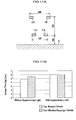
- FIGS. 7A and 7B show an experimental condition of each example
- FIG. 7A is a drawing illustrating symbols showing arranged positions of supplementary lights
- FIG. 7B is a table showing experimental conditions such as the arranged positions shown with the symbols in FIG. 7A.
- a unit of a numeral is mm
- "-" in a column of a comparison example means that a supplementary light is not attached.
- the examples 1-1 and 1-2 were experimented by real vehicles, changing a distance between the upper supplementary lights 12R, 12L and the lower supplementary lights 11R, 11L. In the experiments critical time gaps were measured and averaged for five subjects.
- the critical time gap of a comparison example 1 where a vehicular lighting unit was not attached was around 5.3 seconds; whereas that of the example 1-1 where the up/down distance (to be more accurate, a distance of outer profiles of supplementary lights, hereafter similar) of the supplementary lights 12R, 12L and 11R, 11L was 730 mm was 6.4 seconds, and that of the example 1-2 where the distance was 1715 mm was 6.3 seconds: both critical time gaps became larger by around one second, compared to that of the comparison example 1.
- both examples is enhanced the perceived accuracy of a distance and speed of the oncoming vehicle 36, compared to the comparison example 1, and there exists substantially no difference between the examples 1-1 and 1-2.
- the examples 2-1 and 2-2 were experimented by simulator, changing a distance between the left/right supplementary lights 12L, 11L and 12R, 11R. In the experiments critical time gaps were measured and averaged for four subjects.
- the critical time gap of the comparison example 2 is 4.2 seconds; also in accordance with the examples 2-1 and 2-2, it can be confirmed that the perceived accuracy of a distance and speed of a vehicle is enhanced thanks to a vehicular lighting unit.
- a difference between the critical time gap values of the examples 1-1 and 1-2 and those of the examples 2-1 and 2-2 is that between a real vehicle and a simulator. Because it is confirmed that there occurs a difference of about one second, it can be said that a substantially same effect is recognized in the examples 1-1 and 1-2 and the examples 2-1 and 2-2.
- the examples 3-1, 3-2, and 3.3 were experimented by simulator, changing a distance between left supplementary lights and right supplementary lights.
- the critical time gap of a comparison example 2 where a vehicular lighting unit was not attached was around 4.1 seconds; whereas that of the example 3-1 where the left/right distance of the supplementary lights 12L, 11L and 12R, 11R was 840 mm was 5.0 seconds, that of the example 3-2 where the distance was 660 mm was 5.1 seconds, and that of the example 3-3 where the distance was 240 mm was 5.1 seconds: the three critical time gaps became larger than that of the comparison example 2 by around one second.
- an upper unit and a lower unit are recognized as a group; it can be confirmed that the perceived accuracy of a vehicle is enhanced. Moreover, it can also be confirmed in the range that a substantially equivalent effect can be obtained.
- the vehicular lighting units of the present invention are respectively attached to the two-wheeled vehicle and the four-wheeled passenger vehicle, and the critical time gaps thereof were measured.
- Each vehicular lighting unit was arranged, as shown in FIG. 11A, making the left/right distance of the lower supplementary lights 11R, 11L to be 420 mm; that of the upper supplementary lights 12R, 12L, 660 mm; the up/down distance of the upper and lower supplementary lights, 730 mm; and the distance from the ground G of the supplementary lights 11R, 11L, 300 mm.
- the critical time gap of the two-wheeled vehicle was 4.9 seconds; that of the four-wheeled passenger vehicle was 5.5 seconds. In other words, it can be said that the two-wheeled vehicle was perceived farther and slower.
- the present invention not only enhances the perceived accuracy of a distance and a speed but also has an effect of perceiving the distance and the speed as same even between different vehicle kinds.
- a third example compares an effect between cases of numbers of supplementary lights, two and four.
- the critical time gap was 4.6 seconds; whereas in the case that the total four supplementary lights 12R, 12L, 11R, and 11L were provided at the lower and upper portions, the critical time gap was 4.9 seconds: an enhancement of the perceived accuracy of a distance and a speed is recognized.
Abstract

Description
- The present invention relates to a vehicular lighting unit for enhancing an accuracy of when a driver of another vehicle and a pedestrian looking a vehicle perceive the vehicle, and a vehicle of which a perceived accuracy is enhanced.
- Generally in a traffic environment where a large variety of vehicles run, a larger vehicle is apt to be firstly found by a driver of another vehicle and a pedestrian. In addition, a smaller vehicle such as a two-wheeled vehicle is seen as farther than a larger vehicle such as a truck, and a speed of the former is also felt slower.
- For example, in a case that a two-wheeled vehicle and a truck of which distances from own vehicle are same are nearing from an opposite lane during waiting for a right turn at an intersection, a driver is apt to firstly find the truck. Even if a two-wheeled vehicle is perceived to be farther, and the vehicle and a truck run at a same speed, the vehicle results in being perceived to be slower.
- In order to solve such the problem is conventionally disclosed a technology of attaching a lighting for enhancing a perceived accuracy at a front side and rear side of a two-wheeled vehicle (see
Japanese Patent Laid-Open Publication No. 2003-300488 - In addition, in order to make a driver and a pedestrian recognize an existence of a four-wheeled vehicle during daytime is disclosed a technology of arranging a daytime-run light at lower portion of a headlight, and lighting the light during daytime (see
Japanese Patent Laid-Open Publication No. 2004-51080 - However, although attaching vehicle supplementary lights to respective proper positions of a two-wheeled vehicle and a four-wheeled vehicle contributes to enhancing a perceived accuracy of a distance and a speed for each vehicle, a problem cannot be solved that the distance and the speed are differently perceived between different kinds of vehicles. In addition, the technology disclosed in the
Japanese Patent Laid-Open Publication No. 2004-51080 - Consequently, there is a need for enhancing a perceived accuracy of a vehicle.
- In order to solve the problem, the present invention provides a vehicular lighting unit arranged at a front side not to be in a row and comprising at least not less than three supplementary lights having an equivalent color and brightness.
- In accordance with such the vehicular lighting unit, because supplementary lights having an equivalent color and brightness are plurally arranged, changing a vertical position and a horizontal position, and thereby the plurality of the supplementary lights are grasped as a combination and like a plane, a perceived accuracy of the vehicle is enhanced.
- It is preferable that these supplementary lights are arranged at equivalent positions for any one of a two-wheeled vehicle, a four-wheeled passenger vehicle, and a large size vehicle.
- Thus supplementary lights are arranged at equivalent positions even if vehicle kinds are different, and thereby the vehicle can be perceived with an equivalent distance and speed regardless of the vehicle size.
- Then in the lighting unit each of the supplementary lights arranged outside is preferably in a range of 460 to 1715 mm in a vertical direction. In addition, at least three brightnesses out of the supplementary lights are preferably in a range of ± 40% from an average of the brightnesses. Moreover, in the supplementary lights each one arranged outside is preferably in a range of 240 to 840 mm in a horizontal direction.
- A plurality of supplementary lights are arranged in such the ranges, and thereby become easier to be recognized as a combination. In addition, if in such the ranges, supplementary lights can be arranged at proper positions in various vehicle kinds.
- In addition, it is preferable that the supplementary lights are symmetrically arranged, specifically, from center of left and right of the vehicle. Thus the vehicle position can be accurately perceived.
- In addition, the present invention provides a vehicle where a vehicular lighting unit thus described is attached and thereby a perceived accuracy of the vehicle is enhanced..
-
- FIG. 1A is a front view showing a four-wheeled passenger vehicle where a vehicular lighting unit related to an embodiment of the present invention is attached; FIG. 1B is a drawing showing a preferable attachment range of supplementary lights.
- FIG. 2 is a CIE 1976 UCS chromaticity diagram (XYZ color system) in JIS Z 8729.
- FIGS. 3A and 3B are front views respectively showing examples where a vehicular lighting unit is applied to a two-wheeled vehicle.
- FIGS. 4A and 4B are side views respectively showing cases of placing supplementary lights of a vehicular lighting unit at lower portion of a two-wheeled vehicle; FIG. 4C is a front view showing a case of placing supplementary lights of a vehicular lighting unit at upper portion of a two-wheeled vehicle.
- FIG. 5 is a front view showing a case of placing a vehicular lighting unit in a large size vehicle.
- FIG. 6 is a conceptual drawing showing an experimental method of a first example.
- FIGS. 7A and 7B show an experimental condition of each example; FIG. 7A is a drawing illustrating symbols showing arranged positions of supplementary lights; and FIG. 7B is a table showing an experimental condition of such the arranged positions shown with the symbols in FIG. 7A.
- FIG. 8 is a graph showing results of examples 1-1 and 1-2.
- FIG. 9 is a graph showing results of examples 2-1 and 2-2.
- FIG. 10 is a graph showing results of examples 3-1, 3-2, and 3.3.
- FIG. 11A is a drawing showing an arrangement of supplementary lights when the second examples are performed; FIG. 11B is a graph showing their results.
- FIG. 12A and 12B are drawings showing an arrangement of supplementary lights when the third examples are performed; FIG. 12C is a graph showing their results.
- Here will be described a first embodiment of the present invention in detail, referring to drawings as needed. FIG. 1A is a front view showing a four-wheeled passenger vehicle where a vehicular lighting unit related to the embodiment of the present invention is attached; FIG. 1B is a drawing showing a preferable attachment range of supplementary lights. Meanwhile, hereafter, up/down, left/right, and front/rear are assumed to mean up and down, left and right, and front and rear of a vehicle.
- As shown in FIG. 1A, to a vehicle V1 of a four-wheeled passenger vehicle is attached a
vehicular lighting unit 10 at a front side, that is, so as to light front. Thevehicular lighting unit 10 comprises foursupplementary lights supplementary lights - Making a description more in detail, the
supplementary lights supplementary lights supplementary lights - The
supplementary lights supplementary lights supplementary lights supplementary lights supplementary lights supplementary lights - As the four
supplementary lights - Here, if a same color is in a range of not being felt oddly, compared to a basic lighting color, it is not specifically limited; however, in a case that a viewing angle for an observed lighting is ≤4°, a color is preferable of which a chromaticity from a chromaticity point of a basic lighting color (F1) is within a definite range in the CIE (Commission Internationale de l'Eclairage) 1976 UCS (Uniform-Chromaticity-Scale) chromaticity diagram (XYZ color system) (defined in JIS (Japanese Industrial Standard) Z 8729). For example, in a case that the chromaticity point of the lighting color (F1) is F1(u1', ν1'), and that of a lighting color (F2) compared is F2(u2', ν2'), a chromaticity difference ΔE between the chromaticity point F1 and the chromaticity point F2 are expressed in the following equation (1):

- For example, it is preferable to make a color, of which the chromaticity difference ΔE expressed in the equation (1) is ≤ 0.10, to be a same color.
- Showing a chromaticity diagram for reference, FIG. 2 shows the CIE 1976 UCS chromaticity diagram (XYZ color system) (extracted from JIS Z 8729), and as an area surrounded by dotted line, a range is shown where the chromaticity difference ΔE is ≤ 0.10 from the chromaticity point F1(u1', ν1') of the basic lighting color (F1).
- In addition, a same brightness means a brightness of a range of ± 40% from an average of that of each supplementary light. Mentioning the example of the embodiment, it is meant that the four
supplementary lights - An arranged position of each of the
supplementary lights supplementary lights Japanese Patent Laid-Open Publication No. 2003-300488 supplementary lights - In addition, the
supplementary lights - Thus each of the
supplementary lights supplementary lights supplementary lights - Although a size of each
supplementary light supplementary lights supplementary lights - Assuming that a vehicle running on an opposite lane is running at a speed of 60 km/h, it is preferable that a supplementary light has at least a size of 30 mm in longitudinal and 1200 mm in traversal, and a brightness of ≥ 137 cd/m2 and such a sort not obstructing a traffic (for example, ≤ 300 cd/m2 according to a Japanese regulation).
- Each
supplementary light - Such the
vehicular lighting unit 10 can be applied not only to a four-wheeled passenger vehicle but also to other vehicle kinds. FIGS. 3A and 3B are front views respectively showing examples where a vehicular lighting unit is applied to a two-wheeled vehicle; FIGS. 4A and 4B are side views respectively showing cases of placing supplementary lights of a vehicular lighting unit at lower portion of a two-wheeled vehicle; FIG. 4C is a front view showing a case of placing supplementary lights of a vehicular lighting unit at upper portion of a two-wheeled vehicle; and FIG. 5 is a front view showing a case of placing a vehicular lighting unit in a large size vehicle. - As shown in FIG. 3A, in a case of applying the
vehicular lighting unit 10 to a two-wheeled vehicle of a scooter type, the lowersupplementary lights front fork 21, and the uppersupplementary lights handle 25. Or else, as shown in FIG. 3B, if the uppersupplementary lights front cowl 24, it is possible to make a positional relationship similar to the four-wheeled passenger vehicle of a sport type shown in FIG. 1A. - As shown in FIG. 4A, in a case that the
supplementary lights vehicular lighting unit 10 are placed at lower portions of a two-wheeled vehicle V2' of a middle size or a large size, they can be directly fastened with bolts or fixed with bands at lower ends of thefront fork 21, respectively. In addition, as shown in FIG. 4B, attaching afront stay 22 to thefront fork 21 and thesupplementary lights stay 22, it is also possible to fix thesupplementary lights fork 21 in up/down, left/right, and front/rear. - In addition, although not shown, it is also possible to provide the
supplementary lights front fork 21 or to attach them to an undercowl. - As shown in FIG. 4C, in a case of placing the
supplementary lights vehicular lighting unit 10 at upper portions of the two-wheeled vehicle V2', it is possible to respectively place them at the front side ofrearview mirrors 23 so as to be housed therein. Although not shown, thesupplementary lights front cowl 24 or a handle. - In addition, in a case of attaching the
vehicular lighting unit 10 to a large size vehicle, because the vehicle has a comparatively large and flat front side, it is preferable as shown in FIG. 5 to attach eachsupplementary light - Thus arranging each
supplementary light - In such the
vehicular lighting unit 10 and a vehicle attached with theunit 10, a vehicle position is grasped by theunit 10 regardless of a vehicle body size; theunit 10 and the vehicle are perceived as a similar position and speed by a driver of another vehicle and a pedestrian regardless of its vehicle kind. Therefore, even in a traffic environment where various vehicle kinds are mixed, a position and speed of each vehicle with thevehicular lighting unit 10 are correctly perceived, and thereby a smooth vehicle traffic can be realized. - The present invention is not limited to the embodiment, and it goes without saying that the embodiment can be appropriately changed and performed.
- For example, a number of supplementary lights may not be four, and may be three or not less than five. Also in this case it is preferable that each supplementary light is symmetrically arranged, making center of left/right of a vehicle to be a border.
- In addition, if although it is preferable that each supplementary light has an equivalent color and brightness, not less than three supplementary lights have the equivalent color and brightness, it is acceptable that a color of some supplementary light is slightly different or a brightness thereof is low.
- Next will be described examples of the present invention.
- A first example is an example of experimenting respective relationships of supplementary lights.
- FIG. 6 is a conceptual drawing showing an experimental method of the first example. As shown in FIG. 6, a subject gets on a
subject vehicle 35 on aroad 31 of a width of 10 m; on an opposite lane an oncomingvehicle 36 is made to run at a predetermined speed v. Aligningcones 33 on aroad 32 corresponding to a sideway of a width of 6 m, theroad 32 is connected to theroad 31 in advance, and thesubject vehicle 35 is made to stop in a state of waiting for a right turn from theroad 31 to theroad 32. As a driver of thesubject vehicle 35, the subject, looks for the oncomingvehicle 36 to near, he/she steps on a brake pedal at timing of believing, "if the oncomingvehicle 36 nears more than this, I cannot turn to the right." - Using a distance d between the
subject vehicle 35 and the oncomingvehicle 36 and speed v of the latter of this time, and calculating d/v, a time is obtained from the timing, when the brake pedal was stepped on, to that when thevehicles - In the example, under each condition shown in FIGS. 7A and 7B was experimented how the critical time gap was changed according to positions of supplementary lights.
- FIGS. 7A and 7B show an experimental condition of each example; FIG. 7A is a drawing illustrating symbols showing arranged positions of supplementary lights; and FIG. 7B is a table showing experimental conditions such as the arranged positions shown with the symbols in FIG. 7A. Meanwhile, in FIG. 7B a unit of a numeral is mm, and "-" in a column of a comparison example means that a supplementary light is not attached.
- Firstly will be described examples 1-1 and 1-2.
- The examples 1-1 and 1-2 were experimented by real vehicles, changing a distance between the upper
supplementary lights supplementary lights - As the result, as shown in FIG. 8, the critical time gap of a comparison example 1 where a vehicular lighting unit was not attached was around 5.3 seconds; whereas that of the example 1-1 where the up/down distance (to be more accurate, a distance of outer profiles of supplementary lights, hereafter similar) of the
supplementary lights vehicle 36, compared to the comparison example 1, and there exists substantially no difference between the examples 1-1 and 1-2. - Next will be described examples 2-1 and 2-2.
- The examples 2-1 and 2-2 were experimented by simulator, changing a distance between the left/right
supplementary lights - As the result, as shown in FIG. 9, the critical time gap of the example 2-1 where the up/down distance of the
supplementary lights - Meanwhile, as a conventional example compared to the examples 2-1 and 2-2, although there exists a comparison example 2 of FIG. 10, the critical time gap of the comparison example 2 is 4.2 seconds; also in accordance with the examples 2-1 and 2-2, it can be confirmed that the perceived accuracy of a distance and speed of a vehicle is enhanced thanks to a vehicular lighting unit.
- In addition, a difference between the critical time gap values of the examples 1-1 and 1-2 and those of the examples 2-1 and 2-2 is that between a real vehicle and a simulator. Because it is confirmed that there occurs a difference of about one second, it can be said that a substantially same effect is recognized in the examples 1-1 and 1-2 and the examples 2-1 and 2-2.
- Next will be described examples 3-1, 3-2, and 3.3.
- The examples 3-1, 3-2, and 3.3 were experimented by simulator, changing a distance between left supplementary lights and right supplementary lights. As the result, as shown in FIG. 10, the critical time gap of a comparison example 2 where a vehicular lighting unit was not attached was around 4.1 seconds; whereas that of the example 3-1 where the left/right distance of the
supplementary lights - Thus in the range of 460 to 1715 mm in up/down distance and 240 to 840 mm in left/right distance of the
supplementary lights - Next will be described a second example of comparing an effect between a two-wheeled vehicle (scooter) and a four-wheeled passenger vehicle.
- In the second example the vehicular lighting units of the present invention are respectively attached to the two-wheeled vehicle and the four-wheeled passenger vehicle, and the critical time gaps thereof were measured.
- Each vehicular lighting unit was arranged, as shown in FIG. 11A, making the left/right distance of the lower
supplementary lights supplementary lights supplementary lights - An experimental method was performed by real vehicle.
- As the result, as shown in FIG. 11B, in a case of there existing no supplementary light, the critical time gap of the two-wheeled vehicle was 4.9 seconds; that of the four-wheeled passenger vehicle was 5.5 seconds. In other words, it can be said that the two-wheeled vehicle was perceived farther and slower.
- On the other hand, in a case of there existing supplementary lights, the critical time gaps of both of the two-wheeled vehicle and the four-wheeled passenger vehicle were 6.0 seconds and same. In other words, it can be said that both of the two-wheeled vehicle and the four-wheeled passenger vehicle were perceived as a same distance and speed.
- Accordingly, it is confirmed that the present invention not only enhances the perceived accuracy of a distance and a speed but also has an effect of perceiving the distance and the speed as same even between different vehicle kinds.
- A third example compares an effect between cases of numbers of supplementary lights, two and four.
- With respect to a two-wheeled vehicle (scooter) were measured the critical time gaps in a case that two
supplementary lights 12, 11 were arranged up/down as shown in FIG. 12A; and in a case that the twosupplementary lights supplementary lights supplementary lights - As the result, as shown in FIG. 12C, in the case that the two
supplementary lights 12, 11 were provided up/down only, the critical time gap was 4.6 seconds; whereas in the case that the total foursupplementary lights - Thus by arranging four supplementary lights not in a row but like a plane seen from front, it is confirmed that the perceived accuracy is more enhanced than a case of only two supplementary lights being arranged like a conventional technology.
Claims (7)
- A vehicular lighting unit (10) comprising:at least not less than three supplementary lights (11R, 11L, 12R, 12L) arranged not to be in a row at a front side of a vehicle (V1, V2, V2', V3) and having an equivalent color and brightness.
- The vehicular lighting unit according to claim 1, wherein the supplementary lights are arranged at an equivalent position with respect to any one of a two-wheeled vehicle (V2, V2'), a four-wheeled passenger vehicle (V1), and a large size vehicle (V3).
- The vehicular lighting unit according to claim 1 or 2, wherein in the supplementary lights each one arranged outside is in a range of 460 to 1715 mm in a vertical direction.
- The vehicular lighting unit according to any one of claims 1 to 3, wherein at least three brightnesses out of the supplementary lights are in a range of ±40% from an average of the brightnesses.
- The vehicular lighting unit according to any one of claims 1 to 4, wherein in the supplementary lights each one arranged outside is in a range of 240 to 840 mm in a horizontal direction.
- The vehicular lighting unit according to any one of claims 1 to 5, wherein the supplementary lights are symmetrically arranged.
- The vehicle where the vehicular lighting unit according to any one of claims 1 to 6 is attached at the front side of the vehicle, wherein a perceived accuracy of the vehicle is enhanced.
Applications Claiming Priority (1)
| Application Number | Priority Date | Filing Date | Title |
|---|---|---|---|
| JP2005277193A JP4430599B2 (en) | 2005-09-26 | 2005-09-26 | Vehicle lighting unit and automobile with improved perception accuracy |
Publications (2)
| Publication Number | Publication Date |
|---|---|
| EP1767398A1 true EP1767398A1 (en) | 2007-03-28 |
| EP1767398B1 EP1767398B1 (en) | 2008-11-26 |
Family
ID=37056762
Family Applications (1)
| Application Number | Title | Priority Date | Filing Date |
|---|---|---|---|
| EP06018145A Expired - Fee Related EP1767398B1 (en) | 2005-09-26 | 2006-08-30 | Vehicle with enhanced perceived accuracy |
Country Status (4)
| Country | Link |
|---|---|
| US (1) | US20070070641A1 (en) |
| EP (1) | EP1767398B1 (en) |
| JP (1) | JP4430599B2 (en) |
| DE (1) | DE602006003830D1 (en) |
Cited By (10)
| Publication number | Priority date | Publication date | Assignee | Title |
|---|---|---|---|---|
| EP2213511A1 (en) * | 2009-01-29 | 2010-08-04 | Honda Motor Co., Ltd. | Vehicle lighting system |
| WO2012072191A3 (en) * | 2010-12-03 | 2012-12-20 | Docter Optics Gmbh | Motor vehicle comprising additional front lights |
| US8851722B2 (en) | 2010-12-03 | 2014-10-07 | Docter Optics Se | Headlight lens for a vehicle headlight |
| US8899802B2 (en) | 2010-12-03 | 2014-12-02 | Docter Optics Se | Optical component for illumination purposes |
| US9447939B2 (en) | 2012-05-15 | 2016-09-20 | Docter Optics Se | Headlight lens |
| US9599302B2 (en) | 2011-11-11 | 2017-03-21 | Docter Optics Se | Headlight lens for a vehicle headlight |
| US9719645B2 (en) | 2012-05-26 | 2017-08-01 | Docter Optics Se | Motor vehicle headlight having a complex headlight lens |
| DE102008057638B4 (en) * | 2007-11-29 | 2018-04-26 | Honda Motor Co., Ltd. | Lighting device for a motorcycle |
| US10018323B2 (en) | 2011-11-11 | 2018-07-10 | Docter Optics Se | Vehicle headlight |
| US10107466B2 (en) | 2010-12-03 | 2018-10-23 | Docter Optics Se | Headlight lens for a vehicle headlight |
Families Citing this family (2)
| Publication number | Priority date | Publication date | Assignee | Title |
|---|---|---|---|---|
| JP5087802B2 (en) * | 2007-11-29 | 2012-12-05 | 本田技研工業株式会社 | Motorcycle |
| WO2019180948A1 (en) * | 2018-03-23 | 2019-09-26 | 本田技研工業株式会社 | Object recognition device, vehicle, and object recognition method |
Citations (6)
| Publication number | Priority date | Publication date | Assignee | Title |
|---|---|---|---|---|
| US5590947A (en) * | 1995-10-02 | 1997-01-07 | Kidd, Jr.; Larry W. | Illuminated windscreen for a motorcycle fairing |
| WO1998022308A1 (en) * | 1996-11-22 | 1998-05-28 | Gaelliner Lennart | Headlight arrangement |
| JP2003213644A (en) * | 2002-01-21 | 2003-07-30 | Kyowa Kikai Seisakusho:Kk | Snow discharge control type snow plow |
| EP1473215A1 (en) * | 2002-02-05 | 2004-11-03 | Honda Giken Kogyo Kabushiki Kaisha | Lamp system for motorcycles |
| US20050094409A1 (en) * | 2003-11-03 | 2005-05-05 | Putco, Inc. | Lighted vehicle grille |
| EP1645466A1 (en) * | 2004-10-07 | 2006-04-12 | Yamaha Hatsudoki Kabushiki Kaisha | Method for controlling lighting means of a vehicle and vehicle |
Family Cites Families (1)
| Publication number | Priority date | Publication date | Assignee | Title |
|---|---|---|---|---|
| JPH10175479A (en) * | 1996-12-17 | 1998-06-30 | Pia Kk | Auxiliary light |
-
2005
- 2005-09-26 JP JP2005277193A patent/JP4430599B2/en not_active Expired - Fee Related
-
2006
- 2006-08-30 EP EP06018145A patent/EP1767398B1/en not_active Expired - Fee Related
- 2006-08-30 DE DE602006003830T patent/DE602006003830D1/en active Active
- 2006-09-25 US US11/527,262 patent/US20070070641A1/en not_active Abandoned
Patent Citations (6)
| Publication number | Priority date | Publication date | Assignee | Title |
|---|---|---|---|---|
| US5590947A (en) * | 1995-10-02 | 1997-01-07 | Kidd, Jr.; Larry W. | Illuminated windscreen for a motorcycle fairing |
| WO1998022308A1 (en) * | 1996-11-22 | 1998-05-28 | Gaelliner Lennart | Headlight arrangement |
| JP2003213644A (en) * | 2002-01-21 | 2003-07-30 | Kyowa Kikai Seisakusho:Kk | Snow discharge control type snow plow |
| EP1473215A1 (en) * | 2002-02-05 | 2004-11-03 | Honda Giken Kogyo Kabushiki Kaisha | Lamp system for motorcycles |
| US20050094409A1 (en) * | 2003-11-03 | 2005-05-05 | Putco, Inc. | Lighted vehicle grille |
| EP1645466A1 (en) * | 2004-10-07 | 2006-04-12 | Yamaha Hatsudoki Kabushiki Kaisha | Method for controlling lighting means of a vehicle and vehicle |
Cited By (20)
| Publication number | Priority date | Publication date | Assignee | Title |
|---|---|---|---|---|
| DE102008057638B4 (en) * | 2007-11-29 | 2018-04-26 | Honda Motor Co., Ltd. | Lighting device for a motorcycle |
| EP2213511A1 (en) * | 2009-01-29 | 2010-08-04 | Honda Motor Co., Ltd. | Vehicle lighting system |
| US8297812B2 (en) | 2009-01-29 | 2012-10-30 | Honda Motor Co., Ltd. | Vehicle lighting system |
| US9458975B2 (en) | 2010-12-03 | 2016-10-04 | Docter Optics Se | Headlight lens for a vehicle headlight |
| US9732925B2 (en) | 2010-12-03 | 2017-08-15 | Docter Optics Se | Headlight lens with two tunnel sections for separate light entry surfaces for a vehicle headlight |
| US8899802B2 (en) | 2010-12-03 | 2014-12-02 | Docter Optics Se | Optical component for illumination purposes |
| US8944649B2 (en) | 2010-12-03 | 2015-02-03 | Doctor Optics SE | Vehicle headlight |
| US9243769B2 (en) | 2010-12-03 | 2016-01-26 | Docter Optics Se | Motor vehicle |
| US10107466B2 (en) | 2010-12-03 | 2018-10-23 | Docter Optics Se | Headlight lens for a vehicle headlight |
| US9453628B2 (en) | 2010-12-03 | 2016-09-27 | Docter Optics Se | Headlight lens for a vehicle headlight |
| CN103237683A (en) * | 2010-12-03 | 2013-08-07 | 博士光学欧洲股份公司 | Motor vehicle |
| CN103237683B (en) * | 2010-12-03 | 2016-11-09 | 博士光学欧洲股份公司 | Motor vehicles |
| US9599303B2 (en) | 2010-12-03 | 2017-03-21 | Docter Optics Se | Vehicle headlight |
| WO2012072191A3 (en) * | 2010-12-03 | 2012-12-20 | Docter Optics Gmbh | Motor vehicle comprising additional front lights |
| US9677732B2 (en) | 2010-12-03 | 2017-06-13 | Docter Optics Se | Headlight lens for a vehicle headlight |
| US8851722B2 (en) | 2010-12-03 | 2014-10-07 | Docter Optics Se | Headlight lens for a vehicle headlight |
| US9599302B2 (en) | 2011-11-11 | 2017-03-21 | Docter Optics Se | Headlight lens for a vehicle headlight |
| US10018323B2 (en) | 2011-11-11 | 2018-07-10 | Docter Optics Se | Vehicle headlight |
| US9447939B2 (en) | 2012-05-15 | 2016-09-20 | Docter Optics Se | Headlight lens |
| US9719645B2 (en) | 2012-05-26 | 2017-08-01 | Docter Optics Se | Motor vehicle headlight having a complex headlight lens |
Also Published As
| Publication number | Publication date |
|---|---|
| DE602006003830D1 (en) | 2009-01-08 |
| JP4430599B2 (en) | 2010-03-10 |
| JP2007083949A (en) | 2007-04-05 |
| EP1767398B1 (en) | 2008-11-26 |
| US20070070641A1 (en) | 2007-03-29 |
Similar Documents
| Publication | Publication Date | Title |
|---|---|---|
| EP1767398B1 (en) | Vehicle with enhanced perceived accuracy | |
| EP3369622A1 (en) | Vehicular illumination device | |
| US10046695B2 (en) | Vehicle visibility system | |
| US20160052445A1 (en) | Roof rack with integrated light | |
| US20070222574A1 (en) | Multi vehicle signal ground illumination indicator lamps for turn, hazard and brake signaling to enhance current methods of use | |
| US20150023038A1 (en) | Guide lamp apparatus for vehicle | |
| JP2009123566A (en) | Headlamp for vehicle | |
| US20220017009A1 (en) | Communication light device for vehicles | |
| CN110997407B (en) | Automatic driving vehicle | |
| US20140333429A1 (en) | Front and side vehicle brake indicator system | |
| US20100177529A1 (en) | Automobile brake lamp | |
| US9279556B2 (en) | Guide lamp apparatus for vehicle | |
| EP2213511B1 (en) | Vehicle lighting system | |
| EP1473215B1 (en) | Lamp system for motorcycles | |
| CN114401867A (en) | Drawing device for vehicle | |
| US20110032718A1 (en) | Intersection-breaching emergency response vehicle warning light assembly | |
| US11850995B2 (en) | Headlight for a vehicle having pixel light source modules forming vertically disposed light patterns | |
| Tsutsumi et al. | Long lighting system for enhanced conspicuity of motorcycles | |
| US11498475B2 (en) | Motor vehicle having a projection device | |
| CN113212292A (en) | Vehicle control method and device, vehicle-mounted equipment, vehicle and medium | |
| Sivak et al. | Performance of the first generation of HID headlamps in the US | |
| WO2023189647A1 (en) | Lamp system | |
| KR101956965B1 (en) | Method of controlling the direction indicator lamps of the vehicle | |
| CN112477752A (en) | Vehicle lamp | |
| EP3300950B1 (en) | Straddled vehicle |
Legal Events
| Date | Code | Title | Description |
|---|---|---|---|
| PUAI | Public reference made under article 153(3) epc to a published international application that has entered the european phase |
Free format text: ORIGINAL CODE: 0009012 |
|
| 17P | Request for examination filed |
Effective date: 20060830 |
|
| AK | Designated contracting states |
Kind code of ref document: A1 Designated state(s): AT BE BG CH CY CZ DE DK EE ES FI FR GB GR HU IE IS IT LI LT LU LV MC NL PL PT RO SE SI SK TR |
|
| AX | Request for extension of the european patent |
Extension state: AL BA HR MK YU |
|
| AKX | Designation fees paid |
Designated state(s): DE GB |
|
| 17Q | First examination report despatched |
Effective date: 20080317 |
|
| RTI1 | Title (correction) |
Free format text: VEHICLE WITH ENHANCED PERCEIVED ACCURACY |
|
| GRAP | Despatch of communication of intention to grant a patent |
Free format text: ORIGINAL CODE: EPIDOSNIGR1 |
|
| GRAS | Grant fee paid |
Free format text: ORIGINAL CODE: EPIDOSNIGR3 |
|
| GRAA | (expected) grant |
Free format text: ORIGINAL CODE: 0009210 |
|
| AK | Designated contracting states |
Kind code of ref document: B1 Designated state(s): DE GB |
|
| REG | Reference to a national code |
Ref country code: GB Ref legal event code: FG4D |
|
| REF | Corresponds to: |
Ref document number: 602006003830 Country of ref document: DE Date of ref document: 20090108 Kind code of ref document: P |
|
| RIN2 | Information on inventor provided after grant (corrected) |
Inventor name: UEMATSU, ISAOC/O HONDA R&D CO., LTD. Inventor name: MARUYAMA, KAZUYUKIC/O HONDA R&D CO., LTD. Inventor name: UEMATSU, HIROSHIC/O HONDA R&D CO., LTD. Inventor name: SAKAMOTO, MARIC/O HONDA R&D CO., LTD. Inventor name: TSUTSUMI, YOJIROC/O HONDA R&D CO., LTD. |
|
| PLBE | No opposition filed within time limit |
Free format text: ORIGINAL CODE: 0009261 |
|
| STAA | Information on the status of an ep patent application or granted ep patent |
Free format text: STATUS: NO OPPOSITION FILED WITHIN TIME LIMIT |
|
| 26N | No opposition filed |
Effective date: 20090827 |
|
| PGFP | Annual fee paid to national office [announced via postgrant information from national office to epo] |
Ref country code: DE Payment date: 20130829 Year of fee payment: 8 |
|
| PGFP | Annual fee paid to national office [announced via postgrant information from national office to epo] |
Ref country code: GB Payment date: 20130828 Year of fee payment: 8 |
|
| REG | Reference to a national code |
Ref country code: DE Ref legal event code: R119 Ref document number: 602006003830 Country of ref document: DE |
|
| GBPC | Gb: european patent ceased through non-payment of renewal fee |
Effective date: 20140830 |
|
| REG | Reference to a national code |
Ref country code: DE Ref legal event code: R119 Ref document number: 602006003830 Country of ref document: DE Effective date: 20150303 |
|
| PG25 | Lapsed in a contracting state [announced via postgrant information from national office to epo] |
Ref country code: GB Free format text: LAPSE BECAUSE OF NON-PAYMENT OF DUE FEES Effective date: 20140830 Ref country code: DE Free format text: LAPSE BECAUSE OF NON-PAYMENT OF DUE FEES Effective date: 20150303 |