EP2213411A1 - Automatic cleaning device for machine tool - Google Patents
Automatic cleaning device for machine tool Download PDFInfo
- Publication number
- EP2213411A1 EP2213411A1 EP08848425A EP08848425A EP2213411A1 EP 2213411 A1 EP2213411 A1 EP 2213411A1 EP 08848425 A EP08848425 A EP 08848425A EP 08848425 A EP08848425 A EP 08848425A EP 2213411 A1 EP2213411 A1 EP 2213411A1
- Authority
- EP
- European Patent Office
- Prior art keywords
- workpiece
- machine tool
- cleaning device
- automatic cleaning
- air nozzle
- Prior art date
- Legal status (The legal status is an assumption and is not a legal conclusion. Google has not performed a legal analysis and makes no representation as to the accuracy of the status listed.)
- Withdrawn
Links
Images

Classifications
-
- B—PERFORMING OPERATIONS; TRANSPORTING
- B23—MACHINE TOOLS; METAL-WORKING NOT OTHERWISE PROVIDED FOR
- B23Q—DETAILS, COMPONENTS, OR ACCESSORIES FOR MACHINE TOOLS, e.g. ARRANGEMENTS FOR COPYING OR CONTROLLING; MACHINE TOOLS IN GENERAL CHARACTERISED BY THE CONSTRUCTION OF PARTICULAR DETAILS OR COMPONENTS; COMBINATIONS OR ASSOCIATIONS OF METAL-WORKING MACHINES, NOT DIRECTED TO A PARTICULAR RESULT
- B23Q11/00—Accessories fitted to machine tools for keeping tools or parts of the machine in good working condition or for cooling work; Safety devices specially combined with or arranged in, or specially adapted for use in connection with, machine tools
- B23Q11/0042—Devices for removing chips
- B23Q11/005—Devices for removing chips by blowing
-
- B—PERFORMING OPERATIONS; TRANSPORTING
- B23—MACHINE TOOLS; METAL-WORKING NOT OTHERWISE PROVIDED FOR
- B23Q—DETAILS, COMPONENTS, OR ACCESSORIES FOR MACHINE TOOLS, e.g. ARRANGEMENTS FOR COPYING OR CONTROLLING; MACHINE TOOLS IN GENERAL CHARACTERISED BY THE CONSTRUCTION OF PARTICULAR DETAILS OR COMPONENTS; COMBINATIONS OR ASSOCIATIONS OF METAL-WORKING MACHINES, NOT DIRECTED TO A PARTICULAR RESULT
- B23Q2230/00—Special operations in a machine tool
- B23Q2230/002—Using the spindle for performing a non machining or non measuring operation, e.g. cleaning, actuating a mechanism
Definitions
- the present invention relates to an automatic cleaning device for machine tool for removing chips dispersed around a workpiece during machining.
- a conventional machine tool is provided with an automatic cleaning device that automatically removes chips dispersed on and around a workpiece.
- Such conventional automatic cleaning device for machine tool is described in Patent Literatures 1 and 2, for example.
- Patent Literature 1 machining and cleaning are separated from each other so that chips can be cleaned simultaneously with the machining.
- cross rails support both of a spindle head and a cleaning robot
- the cleaning range of the cleaning robot during machining is limited.
- employment of such support structure causes vibrations generated by an operation of the cleaning robot to be transmitted to the spindle head during machining, and therefore may lower the accuracy in machining the workpiece.
- the cleaning robot moves a chip-sucking nozzle by rotationally moving multiple arms; therefore, each arm needs a drive source of its own. This not only complicates the structure, but also complicates control for operating the robot.
- Patent Literature 1 in the structure of Patent Literature 2, machining and cleaning are separated from each other so that chips can be cleaned simultaneously with the machining.
- a swarf removal unit that sprays a pressurized fluid toward the chips moves only in one direction, and therefore the cleaning range is limited.
- the present invention is made to solve the above problems, and has an objective to provide an automatic cleaning device for machine tool in which cleaning efficiency can be improved by performing cleaning for a large range simultaneously with machining.
- An automatic cleaning device for machine tool which solves the above problems, is characterized by comprising: removal means for removing a chip and a coolant dispersed while a workpiece is machined, to an outside of the machine; and moving means for moving the removal means not only independently from a movement of a rotary tool that machines the workpiece, but also relatively to the workpiece in directions of three orthogonal axes.
- the automatic cleaning device for machine tool which solves the above problems, is characterized in that the removal means is an air nozzle that sprays air, and includes posture control means for controlling a posture of the air nozzle.
- the automatic cleaning device for machine tool which solves the above problems, is characterized in that a machining program for controlling a movement of the rotary tool and a cleaning program for controlling a movement of the removal means performed by the moving means are set separately from each other.
- the removal means can move not only independently from the movement of the rotary tool that machines a workpiece, but also relatively to the workpiece in directions of three orthogonal axes. This allows cleaning to be performed for a large range simultaneously with machining, and therefore allows cleaning efficiency to be improved.
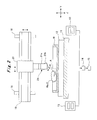
- Fig. 1 is a side view of an automatic cleaning device for machine tool according to an embodiment of the present invention.
- Fig. 2 is a front view of the automatic cleaning device for machine tool according to the embodiment of the present invention.
- Note that an X-axis direction, a Y-axis direction, and a Z-axis direction shown in the drawings indicate directions of three orthogonal axes, and indicate a machine feed direction, a machine width direction, and a vertical direction, respectively.
- a machine tool which is a portal machining center has a bed 11 on which a table 12 is supported while being allowed to move in the X-axis direction.
- a workpiece (a piece of work being machined) W is attached detachably to a top surface of the table 12 with an attachment jig (not shown).
- chip conveyers 13 are provided on both sides of the bed 11 in the Y-axis direction while being allowed to travel in the X-axis direction.
- a chip box 14 and a cutting-oil recovery box 15 are provided downstream in the travel direction of the chip conveyers 13.
- the machine tool is provided with a spindle head 16 which is supported while being allowed to move relative to the bed 11 in the X-axis, Y-axis, and Z-axis directions.
- a tool (rotary tool) T is rotatably and detachably mounted on a tip of the spindle head 16.
- a cutting-oil spray nozzle 17 is provided to a portion of the spindle head 16, the portion being near the mounted tool T.
- the cutting-oil spray nozzle 17 is connected to a cutting-oil supply device (not shown).
- the cutting-oil supply device is configured to supply cutting oil (a coolant) C to the cutting-oil spray nozzle 17.
- a cutting-oil amount and a spray pressure of the cutting oil C sprayed through the cutting-oil spray nozzle 17 are adjusted to predetermined values by the cutting-oil supply device.
- guide members 18 are supported by the bed 11 through a support member (not shown), independently from the table 12.
- the guide members 18 extend in the Z-axis direction.
- a guide rail 19 is supported by front faces of the guide members 18 while being allowed to slide in the Z-axis direction.
- the guide rail 19 extends in the Y-axis direction, and a nozzle head 20 is supported by a front face of the guide rail 19 while being allowed to slide in the Y-axis direction.
- the guide members 18, the guide rail 19, and a nozzle head 20 constitute moving means.
- An air nozzle (removal means) 21 is supported by a tip of the nozzle head 20.
- the air nozzle 21 includes a nozzle support member 21a and a nozzle body 21b (posture control means).
- the nozzle support member 21a is supported, at its one end, by the nozzle head 20, and the nozzle body 21b is supported between vertical walls of the nozzle support member 21 while being allowed to rotate about the X axis. In other words, a spray angle of the air nozzle 21 is adjustable.
- a high-pressure blower 22 is connected to the air nozzle 21, and air A sucked in by the high-pressure blower 22 is sprayed from the air nozzle 21.
- a partition wall 23 is supported by the support member.
- the partition wall 23 is placed between the spindle head 16 and the air nozzle 20. Accordingly, the partition wall 23 divides an area into a work area on the spindle head 16 side and a cleaning area on the air nozzle 21 side.
- the workpiece W is machined into a predetermined shape by moving the spindle head 16 in the X-axis, Y-axis, and Z-axis directions, and also by rotating the tool T mounted on the tip of the spindle head 16.
- the cutting-oil spray nozzle 17 sprays the cutting oil C toward the tool T and a location where the workpiece is being machined by the tool T, to cool the tool T and the workpiece W and to reduce cutting resistance.
- the machining of the workpiece W produces chips Wa from the workpieces W.
- the chips Wa disperse together with the cutting oil C on a surface of the workpiece W and on a surface of the table 12.
- Air blowing by the air nozzle 21 removes the chips Wa and cutting oil C thus dispersed and deposited or attached.
- the air nozzle 21 is moved in the Y-axis and Z-axis directions by moving the guide rail 19 and the nozzle head 20 along with the movement of the table 12 in the X-axis direction during the machining. Furthermore, the rotation position (posture) of the air nozzle 21 is controlled to adjust the spray angle of the air nozzle 21.
- the chips Wa and the cutting oil C deposited on or attached to the workpiece W and the table 12 are dumped on the chip conveyers 13 and transferred by the chip conveyers 13.
- the chips Wa and the cutting oil C transferred by the chip conveyers 13 pass through the chip box 14 where the chips Wa are removed, and then through the cutting-oil recovery box 15 where the rest, namely the cutting oil C, is recovered.
- a machining program for controlling the movement of the spindle head 16 and a cleaning program for performing the movement control and the rotation control (posture control) of the air nozzle 21 are set separately from each other.
- the provision of the partition wall 23 prevents the produced chips Wa and the sprayed cutting oil C from entering the cleaning area, and also prevents the chips Wa and the cutting oil C air-blown by the air nozzle 21 from entering the machining area.
- the air nozzle 21 is supported while being allowed to move in the Y-axis and the Z-axis directions. Note, however, that the air nozzle 21 may be allowed to move in the X-axis direction as well. Such structure further improves cleaning efficiency.
- the air nozzle 21 is allowed to move independent of the movement of the spindle head 16, and to move relative to the workpiece W in the directions of three orthogonal axes.
- the air nozzle 21 can be moved according to deposition (attachment) amounts and deposition (attachment) positions of the chips Wa and the cutting oil C.
- This consequently allows cleaning to be performed for a large range during the machining, and therefore improves cleaning efficiency.
- the posture of the nozzle body 21b is adjustable. This allows the chips Wa and the cutting oil C to be dumped on the chip conveyers 13 reliably.
- the moving speed and the rotation speed of the air nozzle 21 can be changed to further improve cleaning efficiency. Moreover, it is less likely that vibrations generated by the movement and rotation of the air nozzle 21 are transmitted to the spindle head 16. Thus, machining accuracy can be improved.
- the present invention is applicable to a machine tool capable of a long-time, unattended operation.
Landscapes
- Engineering & Computer Science (AREA)
- Mechanical Engineering (AREA)
- Auxiliary Devices For Machine Tools (AREA)
Abstract
Description
- The present invention relates to an automatic cleaning device for machine tool for removing chips dispersed around a workpiece during machining.
- When a workpiece is machined in a machine tool, a large amount of chips are produced from the workpiece. If these chips deposit on or attach to a surface of the workpiece, a machined hole, or the like, the workpiece or a tool may be damaged. Moreover, if the chips disperse over a table on which the workpiece is fixed, positioning accuracy of a workpiece jig attached to the table or of the table per se may be affected. Since the finished workpiece has to be shipped after being cleaned of course, not only the chips but also cutting oil deposited or attached has to be removed.
- Thus, a conventional machine tool is provided with an automatic cleaning device that automatically removes chips dispersed on and around a workpiece. Such conventional automatic cleaning device for machine tool is described in Patent Literatures 1 and 2, for example.
-
- [Patent Literature 1] Japanese Patent No.
3705999 - [Patent Literature 2] Japanese Patent Application Publication No.
Hei 10-180585 - In the structure of Patent Literature 1, machining and cleaning are separated from each other so that chips can be cleaned simultaneously with the machining. However, since cross rails support both of a spindle head and a cleaning robot, the cleaning range of the cleaning robot during machining is limited. Moreover, employment of such support structure causes vibrations generated by an operation of the cleaning robot to be transmitted to the spindle head during machining, and therefore may lower the accuracy in machining the workpiece. In addition, the cleaning robot moves a chip-sucking nozzle by rotationally moving multiple arms; therefore, each arm needs a drive source of its own. This not only complicates the structure, but also complicates control for operating the robot.
- Like Patent Literature 1, in the structure of Patent Literature 2, machining and cleaning are separated from each other so that chips can be cleaned simultaneously with the machining. However, a swarf removal unit that sprays a pressurized fluid toward the chips moves only in one direction, and therefore the cleaning range is limited.
- The present invention is made to solve the above problems, and has an objective to provide an automatic cleaning device for machine tool in which cleaning efficiency can be improved by performing cleaning for a large range simultaneously with machining.
- An automatic cleaning device for machine tool according to the present invention, which solves the above problems, is characterized by comprising: removal means for removing a chip and a coolant dispersed while a workpiece is machined, to an outside of the machine; and moving means for moving the removal means not only independently from a movement of a rotary tool that machines the workpiece, but also relatively to the workpiece in directions of three orthogonal axes.
- The automatic cleaning device for machine tool according to the present invention, which solves the above problems, is characterized in that the removal means is an air nozzle that sprays air, and includes posture control means for controlling a posture of the air nozzle.
- The automatic cleaning device for machine tool according to the present invention, which solves the above problems, is characterized in that a machining program for controlling a movement of the rotary tool and a cleaning program for controlling a movement of the removal means performed by the moving means are set separately from each other.
- Accordingly, in the automatic cleaning device for machine tool according to the present invention, the removal means can move not only independently from the movement of the rotary tool that machines a workpiece, but also relatively to the workpiece in directions of three orthogonal axes. This allows cleaning to be performed for a large range simultaneously with machining, and therefore allows cleaning efficiency to be improved.
-
- [
Fig. 1] Fig. 1 is a side view of an automatic cleaning device for machine tool according to an embodiment of the present invention. - [
Fig. 2] Fig. 2 is a front view of the automatic cleaning device for machine tool according to the embodiment of the present invention. - An automatic cleaning device for machine tool according to the present invention will be described in detail below using the drawings.
Fig. 1 is a side view of an automatic cleaning device for machine tool according to an embodiment of the present invention.Fig. 2 is a front view of the automatic cleaning device for machine tool according to the embodiment of the present invention. Note that an X-axis direction, a Y-axis direction, and a Z-axis direction shown in the drawings indicate directions of three orthogonal axes, and indicate a machine feed direction, a machine width direction, and a vertical direction, respectively. - As
Figs. 1 and2 show, a machine tool (not shown) which is a portal machining center has abed 11 on which a table 12 is supported while being allowed to move in the X-axis direction. A workpiece (a piece of work being machined) W is attached detachably to a top surface of the table 12 with an attachment jig (not shown). In addition,chip conveyers 13 are provided on both sides of thebed 11 in the Y-axis direction while being allowed to travel in the X-axis direction. Achip box 14 and a cutting-oil recovery box 15 are provided downstream in the travel direction of thechip conveyers 13. - Further, the machine tool is provided with a
spindle head 16 which is supported while being allowed to move relative to thebed 11 in the X-axis, Y-axis, and Z-axis directions. A tool (rotary tool) T is rotatably and detachably mounted on a tip of thespindle head 16. A cutting-oil spray nozzle 17 is provided to a portion of thespindle head 16, the portion being near the mounted tool T. The cutting-oil spray nozzle 17 is connected to a cutting-oil supply device (not shown). Specifically, the cutting-oil supply device is configured to supply cutting oil (a coolant) C to the cutting-oil spray nozzle 17. A cutting-oil amount and a spray pressure of the cutting oil C sprayed through the cutting-oil spray nozzle 17 are adjusted to predetermined values by the cutting-oil supply device. - Further,
guide members 18 are supported by thebed 11 through a support member (not shown), independently from the table 12. Theguide members 18 extend in the Z-axis direction. Aguide rail 19 is supported by front faces of theguide members 18 while being allowed to slide in the Z-axis direction. Further, theguide rail 19 extends in the Y-axis direction, and anozzle head 20 is supported by a front face of theguide rail 19 while being allowed to slide in the Y-axis direction. Note that theguide members 18, theguide rail 19, and anozzle head 20 constitute moving means. - An air nozzle (removal means) 21 is supported by a tip of the
nozzle head 20. Theair nozzle 21 includes anozzle support member 21a and anozzle body 21b (posture control means). Thenozzle support member 21a is supported, at its one end, by thenozzle head 20, and thenozzle body 21b is supported between vertical walls of thenozzle support member 21 while being allowed to rotate about the X axis. In other words, a spray angle of theair nozzle 21 is adjustable. A high-pressure blower 22 is connected to theair nozzle 21, and air A sucked in by the high-pressure blower 22 is sprayed from theair nozzle 21. - Moreover, a
partition wall 23 is supported by the support member. Thepartition wall 23 is placed between thespindle head 16 and theair nozzle 20. Accordingly, thepartition wall 23 divides an area into a work area on thespindle head 16 side and a cleaning area on theair nozzle 21 side. - Accordingly, the workpiece W is machined into a predetermined shape by moving the
spindle head 16 in the X-axis, Y-axis, and Z-axis directions, and also by rotating the tool T mounted on the tip of thespindle head 16. During this machining, the cutting-oil spray nozzle 17 sprays the cutting oil C toward the tool T and a location where the workpiece is being machined by the tool T, to cool the tool T and the workpiece W and to reduce cutting resistance. - The machining of the workpiece W produces chips Wa from the workpieces W. The chips Wa disperse together with the cutting oil C on a surface of the workpiece W and on a surface of the table 12. Air blowing by the
air nozzle 21 removes the chips Wa and cutting oil C thus dispersed and deposited or attached. - In sum, the
air nozzle 21 is moved in the Y-axis and Z-axis directions by moving theguide rail 19 and thenozzle head 20 along with the movement of the table 12 in the X-axis direction during the machining. Furthermore, the rotation position (posture) of theair nozzle 21 is controlled to adjust the spray angle of theair nozzle 21. Thereby, the chips Wa and the cutting oil C deposited on or attached to the workpiece W and the table 12 are dumped on thechip conveyers 13 and transferred by thechip conveyers 13. Next, the chips Wa and the cutting oil C transferred by thechip conveyers 13 pass through thechip box 14 where the chips Wa are removed, and then through the cutting-oil recovery box 15 where the rest, namely the cutting oil C, is recovered. - Here, since the
spindle head 16 and theair nozzle 21 are supported separately, the machining by the tool T and the air blowing by theair nozzle 21 are performed simultaneously. More precisely, to prevent interference between the machining operations and the cleaning operations, a machining program for controlling the movement of thespindle head 16 and a cleaning program for performing the movement control and the rotation control (posture control) of theair nozzle 21 are set separately from each other. Note that the provision of thepartition wall 23 prevents the produced chips Wa and the sprayed cutting oil C from entering the cleaning area, and also prevents the chips Wa and the cutting oil C air-blown by theair nozzle 21 from entering the machining area. - In the embodiment, the
air nozzle 21 is supported while being allowed to move in the Y-axis and the Z-axis directions. Note, however, that theair nozzle 21 may be allowed to move in the X-axis direction as well. Such structure further improves cleaning efficiency. - Accordingly, in the automatic cleaning device for machine tool according to the present invention, the
air nozzle 21 is allowed to move independent of the movement of thespindle head 16, and to move relative to the workpiece W in the directions of three orthogonal axes. Thereby, theair nozzle 21 can be moved according to deposition (attachment) amounts and deposition (attachment) positions of the chips Wa and the cutting oil C. This consequently allows cleaning to be performed for a large range during the machining, and therefore improves cleaning efficiency. In addition, since thenozzle body 21b of theair nozzle 21 is supported while being allowed to rotate about the X axis, the posture of thenozzle body 21b is adjustable. This allows the chips Wa and the cutting oil C to be dumped on thechip conveyers 13 reliably. Further, the moving speed and the rotation speed of theair nozzle 21 can be changed to further improve cleaning efficiency. Moreover, it is less likely that vibrations generated by the movement and rotation of theair nozzle 21 are transmitted to thespindle head 16. Thus, machining accuracy can be improved. - The present invention is applicable to a machine tool capable of a long-time, unattended operation.
Claims (3)
- An automatic cleaning device for machine tool, characterized by comprising:removal means for removing a chip and a coolant dispersed while a workpiece is machined, to an outside of the machine; andmoving means for moving the removal means not only independently from a movement of a rotary tool that machines the workpiece, but also relatively to the workpiece in directions of three orthogonal axes.
- The automatic cleaning device for machine tool according to claim 1, characterized in that the removal means is an air nozzle that sprays air, and includes posture control means for controlling a posture of the air nozzle.
- The automatic cleaning device for machine tool according to claim 1, characterized in that a machining program for controlling a movement of the rotary tool and a cleaning program for controlling a movement of the removal means performed by the moving means are set separately from each other.
Applications Claiming Priority (2)
| Application Number | Priority Date | Filing Date | Title |
|---|---|---|---|
| JP2007291643A JP2009113182A (en) | 2007-11-09 | 2007-11-09 | Automatic cleaning device for machine tool |
| PCT/JP2008/069086 WO2009060714A1 (en) | 2007-11-09 | 2008-10-22 | Automatic cleaning device for machine tool |
Publications (2)
| Publication Number | Publication Date |
|---|---|
| EP2213411A1 true EP2213411A1 (en) | 2010-08-04 |
| EP2213411A4 EP2213411A4 (en) | 2013-04-10 |
Family
ID=40625614
Family Applications (1)
| Application Number | Title | Priority Date | Filing Date |
|---|---|---|---|
| EP08848425.8A Withdrawn EP2213411A4 (en) | 2007-11-09 | 2008-10-22 | Automatic cleaning device for machine tool |
Country Status (7)
| Country | Link |
|---|---|
| US (1) | US20100293739A1 (en) |
| EP (1) | EP2213411A4 (en) |
| JP (1) | JP2009113182A (en) |
| KR (1) | KR20100076009A (en) |
| CN (1) | CN101848789A (en) |
| TW (1) | TW200936296A (en) |
| WO (1) | WO2009060714A1 (en) |
Cited By (2)
| Publication number | Priority date | Publication date | Assignee | Title |
|---|---|---|---|---|
| TWI415699B (en) * | 2011-01-03 | 2013-11-21 | ||
| CN104209824A (en) * | 2013-06-04 | 2014-12-17 | 桂林广陆数字测控股份有限公司 | Automatic surface grinding machine working table cleaning method and device |
Families Citing this family (19)
| Publication number | Priority date | Publication date | Assignee | Title |
|---|---|---|---|---|
| US9278416B2 (en) | 2010-09-15 | 2016-03-08 | Steve Simons | Automated loading of work pieces into adverse environments associated with milling machines |
| US8931622B2 (en) * | 2010-09-15 | 2015-01-13 | Steve Simons | Automated loading of work pieces via staging regions into adverse environments associated with milling machines and controllers and methods for same |
| CN104511450A (en) * | 2013-09-27 | 2015-04-15 | 富鼎电子科技(嘉善)有限公司 | Blowing cleaning device |
| CN103769395B (en) * | 2014-01-24 | 2016-01-06 | 江苏大卫精工科技有限公司 | Machine tool workbench cleaning device |
| JP6385263B2 (en) * | 2014-12-03 | 2018-09-05 | 三菱重工工作機械株式会社 | Dry processing equipment |
| US10086487B2 (en) | 2014-12-25 | 2018-10-02 | Fanuc Corporation | Internal cleaning device of machine tool |
| CN105150019A (en) * | 2015-10-08 | 2015-12-16 | 宁波德玛智能机械有限公司 | Automatic air blowing device of numerically controlled lathe |
| JP6666112B2 (en) | 2015-10-27 | 2020-03-13 | ファナック株式会社 | Tool cleaning equipment for machine tools |
| JP6356655B2 (en) * | 2015-12-10 | 2018-07-11 | ファナック株式会社 | Machining system with function to remove machining waste |
| CN106423930A (en) * | 2016-11-29 | 2017-02-22 | 严建低 | Efficient grinding machine cleaning device special for driverless car parts |
| CN107791043A (en) * | 2017-12-01 | 2018-03-13 | 江苏新瑞重工科技有限公司 | Multistation shape extrusion lathe |
| US10821485B2 (en) * | 2018-06-08 | 2020-11-03 | General Electric Company | System and method of powder removal |
| CN109227215B (en) * | 2018-11-30 | 2021-04-06 | 西安精雕软件科技有限公司 | Automatic flexible cleaning device for medium and large-sized part scraps |
| CN109396935A (en) * | 2018-12-11 | 2019-03-01 | 富曜半导体(昆山)有限公司 | CNC CNC milling machine automatic air blowing cleaning device |
| JP6751790B1 (en) * | 2019-03-15 | 2020-09-09 | Dmg森精機株式会社 | Machine tool chip processing equipment and chip processing method |
| CN113649854B (en) * | 2021-09-10 | 2023-04-28 | 珠海格力智能装备有限公司 | Machine tool, control method and control device for machine tool, and machine tool processing system |
| CN116587054B (en) * | 2023-07-17 | 2024-07-19 | 珠海格力智能装备技术研究院有限公司 | Machine tools and chip flushing methods for machine tools |
| CN117226590A (en) * | 2023-11-03 | 2023-12-15 | 北京工商大学 | A machine tool chip removal system device with intelligent follow-up characteristics and its working method |
| CN118061305B (en) * | 2024-02-21 | 2025-09-26 | 上海维宏电子科技股份有限公司 | Method, device, processor and computer-readable storage medium for realizing intelligent four-way air blowing operation for cutting based on motion control system |
Family Cites Families (14)
| Publication number | Priority date | Publication date | Assignee | Title |
|---|---|---|---|---|
| JPS60228053A (en) * | 1984-04-23 | 1985-11-13 | Nitto Kohki Co Ltd | Chuck cleaning apparatus in working system for work |
| JPS61252046A (en) * | 1985-05-02 | 1986-11-10 | Yasunaga Tekkosho:Kk | Automatic chip removing device |
| JPS62172541U (en) * | 1986-04-23 | 1987-11-02 | ||
| JPH06277976A (en) * | 1993-03-26 | 1994-10-04 | Sony Corp | Cutting work device |
| JPH06277977A (en) * | 1993-03-31 | 1994-10-04 | Hino Motors Ltd | Chip removing device |
| US5615984A (en) * | 1995-07-28 | 1997-04-01 | Oberbreckling; Lester W. | Machining tool and automated air-burst control device for use with a machining tool |
| JPH10180585A (en) * | 1996-11-06 | 1998-07-07 | Makino Milling Mach Co Ltd | Machine tools with automatic chip removal equipment |
| JP2000126980A (en) * | 1998-10-23 | 2000-05-09 | Festo Ag & Co | Working fluid injector for machine tool |
| JP2000288865A (en) * | 1999-04-08 | 2000-10-17 | Nippon Steel Corp | Chip removal equipment |
| JP2001212735A (en) * | 2000-01-31 | 2001-08-07 | Ebara Corp | Oil mist injecting device and its controlling method |
| JP3705999B2 (en) | 2000-05-17 | 2005-10-12 | オークマ株式会社 | Chip cleaning equipment for machine tools |
| JP4091764B2 (en) * | 2001-12-19 | 2008-05-28 | 東芝機械株式会社 | Fluid supply device for workpiece processing |
| JP2005288678A (en) * | 2004-03-31 | 2005-10-20 | Yuichiro Koike | Chip collecting device and chip collecting method |
| JP4522354B2 (en) * | 2005-11-18 | 2010-08-11 | 本田技研工業株式会社 | Blow clean device |
-
2007
- 2007-11-09 JP JP2007291643A patent/JP2009113182A/en active Pending
-
2008
- 2008-10-22 KR KR1020107009985A patent/KR20100076009A/en not_active Ceased
- 2008-10-22 WO PCT/JP2008/069086 patent/WO2009060714A1/en not_active Ceased
- 2008-10-22 CN CN200880114534A patent/CN101848789A/en active Pending
- 2008-10-22 US US12/741,889 patent/US20100293739A1/en not_active Abandoned
- 2008-10-22 EP EP08848425.8A patent/EP2213411A4/en not_active Withdrawn
- 2008-10-27 TW TW097141218A patent/TW200936296A/en unknown
Cited By (2)
| Publication number | Priority date | Publication date | Assignee | Title |
|---|---|---|---|---|
| TWI415699B (en) * | 2011-01-03 | 2013-11-21 | ||
| CN104209824A (en) * | 2013-06-04 | 2014-12-17 | 桂林广陆数字测控股份有限公司 | Automatic surface grinding machine working table cleaning method and device |
Also Published As
| Publication number | Publication date |
|---|---|
| TW200936296A (en) | 2009-09-01 |
| EP2213411A4 (en) | 2013-04-10 |
| CN101848789A (en) | 2010-09-29 |
| US20100293739A1 (en) | 2010-11-25 |
| KR20100076009A (en) | 2010-07-05 |
| WO2009060714A1 (en) | 2009-05-14 |
| JP2009113182A (en) | 2009-05-28 |
Similar Documents
| Publication | Publication Date | Title |
|---|---|---|
| US20100293739A1 (en) | Automatic cleaning device for machine tool | |
| US20180056465A1 (en) | Fluid ejection device | |
| CN100408260C (en) | Composite working machine tool and working method in composite working machine tool | |
| JP5385675B2 (en) | Machine tools for turning | |
| EP2698228B1 (en) | Machine tool with abrasive water jet machining device | |
| JPH10180585A (en) | Machine tools with automatic chip removal equipment | |
| US20100130106A1 (en) | Machine tool with cooling nozzle and method for applying cooling fluid | |
| JPH10118884A (en) | Cutting liquid spraying system in machining | |
| KR101914605B1 (en) | Machine tool with y-axis | |
| US20080254959A1 (en) | Universal head and machine tool with universal head | |
| RU166940U1 (en) | LASER TURNING-MILLING-GRINDING MACHINING CENTER | |
| CN105904268B (en) | Lathe | |
| WO2008013313A1 (en) | Automatic lathe having a plurality of tool rests | |
| JP6199511B1 (en) | Combined processing apparatus and combined processing method | |
| KR101942002B1 (en) | Intelligent cutting oil jet apparatus and jet method thereof | |
| JP2020062734A (en) | Chip induction device | |
| JP2018027612A (en) | Composite machining apparatus | |
| JPWO2018235429A1 (en) | Attachment for machining equipment | |
| KR20160092326A (en) | Machine tool | |
| CN110799303B (en) | machine tool | |
| KR101593832B1 (en) | Cleaning Tools | |
| EP3581327B1 (en) | Machine tool | |
| JP5887158B2 (en) | Processing tools and machine tools | |
| KR100738385B1 (en) | Ultra narrow vertical machining center | |
| KR20140103383A (en) | Machine tool with flushing apparatus |
Legal Events
| Date | Code | Title | Description |
|---|---|---|---|
| PUAI | Public reference made under article 153(3) epc to a published international application that has entered the european phase |
Free format text: ORIGINAL CODE: 0009012 |
|
| 17P | Request for examination filed |
Effective date: 20100429 |
|
| AK | Designated contracting states |
Kind code of ref document: A1 Designated state(s): AT BE BG CH CY CZ DE DK EE ES FI FR GB GR HR HU IE IS IT LI LT LU LV MC MT NL NO PL PT RO SE SI SK TR |
|
| AX | Request for extension of the european patent |
Extension state: AL BA MK RS |
|
| DAX | Request for extension of the european patent (deleted) | ||
| A4 | Supplementary search report drawn up and despatched |
Effective date: 20130307 |
|
| RIC1 | Information provided on ipc code assigned before grant |
Ipc: B23Q 11/00 20060101AFI20130301BHEP |
|
| STAA | Information on the status of an ep patent application or granted ep patent |
Free format text: STATUS: THE APPLICATION IS DEEMED TO BE WITHDRAWN |
|
| 18D | Application deemed to be withdrawn |
Effective date: 20131008 |