EP2213255B1 - Energieabgabealgorithmus für medizinische Vorrichtungen - Google Patents
Energieabgabealgorithmus für medizinische Vorrichtungen Download PDFInfo
- Publication number
- EP2213255B1 EP2213255B1 EP10150563A EP10150563A EP2213255B1 EP 2213255 B1 EP2213255 B1 EP 2213255B1 EP 10150563 A EP10150563 A EP 10150563A EP 10150563 A EP10150563 A EP 10150563A EP 2213255 B1 EP2213255 B1 EP 2213255B1
- Authority
- EP
- European Patent Office
- Prior art keywords
- tissue
- impedance
- controller
- generator
- decreasing
- Prior art date
- Legal status (The legal status is an assumption and is not a legal conclusion. Google has not performed a legal analysis and makes no representation as to the accuracy of the status listed.)
- Active
Links
- 230000008859 change Effects 0.000 claims abstract description 17
- 230000003247 decreasing effect Effects 0.000 claims description 37
- 230000000630 rising effect Effects 0.000 claims description 32
- 230000007423 decrease Effects 0.000 claims description 28
- 210000001519 tissue Anatomy 0.000 description 160
- 238000000034 method Methods 0.000 description 31
- 230000004044 response Effects 0.000 description 17
- 238000010586 diagram Methods 0.000 description 15
- 230000006870 function Effects 0.000 description 13
- 238000002679 ablation Methods 0.000 description 10
- 230000000694 effects Effects 0.000 description 8
- 239000000523 sample Substances 0.000 description 8
- 230000008569 process Effects 0.000 description 6
- 230000004913 activation Effects 0.000 description 4
- 230000006399 behavior Effects 0.000 description 4
- 238000005520 cutting process Methods 0.000 description 4
- 238000007789 sealing Methods 0.000 description 4
- 230000001276 controlling effect Effects 0.000 description 3
- 238000003825 pressing Methods 0.000 description 3
- 238000012545 processing Methods 0.000 description 3
- 230000001105 regulatory effect Effects 0.000 description 3
- DSCFFEYYQKSRSV-KLJZZCKASA-N D-pinitol Chemical compound CO[C@@H]1[C@@H](O)[C@@H](O)[C@H](O)[C@H](O)[C@H]1O DSCFFEYYQKSRSV-KLJZZCKASA-N 0.000 description 2
- 230000001934 delay Effects 0.000 description 2
- 238000001514 detection method Methods 0.000 description 2
- 239000000203 mixture Substances 0.000 description 2
- 230000004048 modification Effects 0.000 description 2
- 238000012986 modification Methods 0.000 description 2
- 238000012544 monitoring process Methods 0.000 description 2
- 238000001356 surgical procedure Methods 0.000 description 2
- 230000000451 tissue damage Effects 0.000 description 2
- 231100000827 tissue damage Toxicity 0.000 description 2
- 238000012935 Averaging Methods 0.000 description 1
- 239000012190 activator Substances 0.000 description 1
- 230000015572 biosynthetic process Effects 0.000 description 1
- 230000000740 bleeding effect Effects 0.000 description 1
- 210000004204 blood vessel Anatomy 0.000 description 1
- 210000004556 brain Anatomy 0.000 description 1
- 238000004364 calculation method Methods 0.000 description 1
- 230000015271 coagulation Effects 0.000 description 1
- 238000005345 coagulation Methods 0.000 description 1
- 238000004891 communication Methods 0.000 description 1
- 238000010276 construction Methods 0.000 description 1
- 230000006378 damage Effects 0.000 description 1
- 230000001419 dependent effect Effects 0.000 description 1
- 238000001035 drying Methods 0.000 description 1
- 230000009977 dual effect Effects 0.000 description 1
- 238000001914 filtration Methods 0.000 description 1
- 238000010438 heat treatment Methods 0.000 description 1
- 230000036571 hydration Effects 0.000 description 1
- 238000006703 hydration reaction Methods 0.000 description 1
- 230000003993 interaction Effects 0.000 description 1
- 210000000936 intestine Anatomy 0.000 description 1
- 239000007788 liquid Substances 0.000 description 1
- 210000004072 lung Anatomy 0.000 description 1
- 239000000463 material Substances 0.000 description 1
- 238000005259 measurement Methods 0.000 description 1
- 230000007246 mechanism Effects 0.000 description 1
- 238000002156 mixing Methods 0.000 description 1
- 230000000704 physical effect Effects 0.000 description 1
- 210000004872 soft tissue Anatomy 0.000 description 1
- 238000012360 testing method Methods 0.000 description 1
- 230000001960 triggered effect Effects 0.000 description 1
Images


Classifications
-
- A—HUMAN NECESSITIES
- A61—MEDICAL OR VETERINARY SCIENCE; HYGIENE
- A61B—DIAGNOSIS; SURGERY; IDENTIFICATION
- A61B18/00—Surgical instruments, devices or methods for transferring non-mechanical forms of energy to or from the body
- A61B18/04—Surgical instruments, devices or methods for transferring non-mechanical forms of energy to or from the body by heating
- A61B18/12—Surgical instruments, devices or methods for transferring non-mechanical forms of energy to or from the body by heating by passing a current through the tissue to be heated, e.g. high-frequency current
- A61B18/1206—Generators therefor
-
- A—HUMAN NECESSITIES
- A61—MEDICAL OR VETERINARY SCIENCE; HYGIENE
- A61B—DIAGNOSIS; SURGERY; IDENTIFICATION
- A61B18/00—Surgical instruments, devices or methods for transferring non-mechanical forms of energy to or from the body
- A61B2018/00636—Sensing and controlling the application of energy
- A61B2018/00666—Sensing and controlling the application of energy using a threshold value
- A61B2018/00678—Sensing and controlling the application of energy using a threshold value upper
-
- A—HUMAN NECESSITIES
- A61—MEDICAL OR VETERINARY SCIENCE; HYGIENE
- A61B—DIAGNOSIS; SURGERY; IDENTIFICATION
- A61B18/00—Surgical instruments, devices or methods for transferring non-mechanical forms of energy to or from the body
- A61B2018/00636—Sensing and controlling the application of energy
- A61B2018/00696—Controlled or regulated parameters
- A61B2018/00702—Power or energy
-
- A—HUMAN NECESSITIES
- A61—MEDICAL OR VETERINARY SCIENCE; HYGIENE
- A61B—DIAGNOSIS; SURGERY; IDENTIFICATION
- A61B18/00—Surgical instruments, devices or methods for transferring non-mechanical forms of energy to or from the body
- A61B2018/00636—Sensing and controlling the application of energy
- A61B2018/00773—Sensed parameters
- A61B2018/00875—Resistance or impedance
Definitions
- the present disclosure relates to electrosurgical apparatuses, systems and methods. More particularly, the present disclosure is directed to an algorithm that controls the application of energy to tissue.
- Electrosurgical generators are employed by surgeons in conjunction with an electrosurgical instrument to cut, coagulate, desiccate and/or seal patient tissue.
- High frequency electrical energy e.g., radio frequency (RF) energy
- RF radio frequency
- Electrosurgical techniques and instruments can be used to coagulate small diameter blood vessels or to seal large diameter vessels or tissue, e.g., soft tissue structures, such as lung, brain and intestine.
- a surgeon can either cauterize, coagulate/desiccate and/or simply reduce or slow bleeding, by controlling the intensity, frequency and duration of the electrosurgical energy applied between the electrodes and through the tissue.
- it is necessary to control the output from the electrosurgical generator, e.g., power, waveform, voltage, current, pulse rate, etc.
- the particular waveform of electrosurgical energy can be tailored to enhance a desired surgical effect, e.g., cutting, coagulation, sealing, blend, etc.
- the "cutting" mode typically entails generating an uninterrupted sinusoidal waveform in the frequency range of 100 kHz to 4 MHz with a crest factor in the range of 1.4 to 2.0.
- the "blend” mode typically entails generating an uninterrupted cut waveform with a duty cycle in the range of 25% to 75% and a crest factor in the range of 2.0 to 5.0.
- the "coagulate” mode typically entails generating an uninterrupted waveform with a duty cycle of approximately 10% or less and a crest factor in the range of 5.0 to 12.0.
- a pulse-like waveform is preferred.
- Energy may be supplied in a continuous fashion to seal vessels in tissue if the energy input/output is responsive to tissue hydration/volume through feedback control. Delivery of the electrosurgical energy in pulses allows the tissue to cool down and also allows some moisture to return to the tissue between pulses which are both known to enhance the sealing process.
- the present invention provides an electrosurgical generator as defined in claim 1.
- Fig. 1A is a schematic block diagram of a monopolar electrosurgical system according to the present disclosure
- Fig. 1B is a schematic block diagram of a bipolar electrosurgical system according to the present disclosure
- Fig. 2 is a schematic block diagram of a generator control system according to one embodiment of the present disclosure
- Fig. 3 illustrates a relationship between a tissue conductivity vs. temperature curve and a tissue impedance vs. temperature curve for tissue undergoing treatment
- Fig. 4A is a schematic block diagram of a control algorithm according to the invention.
- Fig. 4B is a schematic block diagram of a control algorithm according to the invention.
- Fig. 5 is a schematic block diagram of a dual loop control system not forming part of the invention for use with the generator of Fig. 2 ;
- Fig. 6A is a schematic block diagram of a normal priority task algorithm not forming part of the invention.
- Fig. 6B is a schematic block diagram of a high priority task algorithm not forming part of the invention.
- Fig. 6C is a schematic block diagram of a low priority task algorithm not forming part of the invention.
- Fig. 7A is a schematic block diagram of a software system for use with the generator of Fig. 2 not forming part of the invention
- Fig. 7B is a schematic block diagram of a normal priority task algorithm not forming part of the invention for use with the software system of Fig. 7A ;
- Figs. 7C is a schematic block diagram of a high priority task atgorithm not forming part of the invention for use with the software system of Fig. 7A ;
- Fig. 7D is a schematic block diagram of a normal priority task algorithm not forming part of the invention for use with the software system of Fig. 7A ;
- Fig. 8 is a schematic block diagram of a user interface not forming part of the invention for use with the generator and software system according to embodiments of the present disclosure.
- a generator according to the present disclosure can perform monopolar and bipolar electrosurgical procedures, including tissue ablation procedures.
- the generator may include a plurality of outputs for interfacing with various electrosurgical instruments (e.g., a monopolar active electrode, return electrode, bipolar electrosurgical forceps, footswitch, etc.).
- various electrosurgical instruments e.g., a monopolar active electrode, return electrode, bipolar electrosurgical forceps, footswitch, etc.
- the generator includes electronic circuitry configured for generating radio frequency power specifically suited for various electrosurgical modes (e.g., cutting, blending, division, etc.) and procedures (e.g., monopolar, bipolar, vessel sealing).
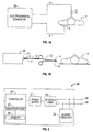
- Fig. 1A is a schematic illustration of a monopolar electrosurgical system according to one embodiment of the present disclosure.
- the system includes a monopolar electrosurgical instrument 2 including one or more active electrodes 3, which can be electrosurgical cutting probes, ablation electrode(s), etc.
- Electrosurgical RF energy is supplied to the instrument 2 by a generator 20 via a supply line 4, which is connected to an active terminal 30 ( Fig. 2 ) of the generator 20, allowing the instrument 2 to coagulate, ablate and/or otherwise treat tissue.
- the energy is returned to the generator 20 through a return electrode 6 via a return line 8 at a return terminal 32 ( Fig. 2 ) of the generator 20.
- the active terminal 30 and the return terminal 32 are connectors configured to interface with plugs (not explicitly shown) of the instrument 2 and the return electrode 6, which are disposed at the ends of the supply line 4 and the return line 8, respectively.
- the system may include a plurality of return electrodes 6 that are arranged to minimize the chances of tissue damage by maximizing the overall contact area with the patient P.
- the generator 20 and the return electrode 6 may be configured for monitoring so-called "tissue-to-patient" contact to insure that sufficient contact exists therebetween to further minimize chances of tissue damage.
- Fig. 1B is a schematic illustration of a bipolar electrosurgical system according to the present disclosure.
- the system includes a bipolar electrosurgical forceps 10 having one or more electrodes for treating tissue of a patient P.
- the electrosurgical forceps 10 include opposing jaw members having an active electrode 14 and a return electrode 16 disposed therein.
- the active electrode 14 and the return electrode 16 are connected to the generator 20 through cable 18, which includes the supply and return lines 4, 8 coupled to the active and return terminals 30, 32, respectively ( Fig. 2 ).
- the electrosurgical forceps 10 are coupled to the generator 20 at a connector 21 having connections to the active and return terminals 30 and 32 (e.g., pins) via a plug disposed at the end of the cable 18, wherein the plug includes contacts from the supply and return lines 4, 8.
- the generator 20 includes suitable input controls (e.g., buttons, activators, switches, touch screen, etc.) for controlling the generator 20, as well as one or more display screens for providing the surgeon with variety of output information (e.g., intensity settings, treatment complete indicators, etc.).
- the controls allow the surgeon to adjust power of the RF energy, waveform, and other parameters to achieve the desired waveform suitable for a particular task (e.g., tissue ablation).
- the instrument 2 may include a plurality of input controls which may be redundant with certain input controls of the generator 20. Placing the input controls at the instrument 2 allows for easier and faster modification of RF energy parameters during the surgical procedure without requiring interaction with the generator 20.
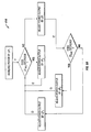
- Fig. 2 shows a schematic block diagram of the generator 20 having a controller 24, a power supply 27, an RF output stage 28, and a sensor module 22.
- the power supply 27 may provide DC power to the RF output stage 28 which then converts the DC power into RF energy and delivers the RF energy to the instrument 2.
- the controller 24 includes a microprocessor 25 having a memory 26 which may be volatile type memory (e.g., RAM) and/or non-volatile type memory (e.g., flash media, disk media, etc.).
- the microprocessor 25 includes an output port connected to the power supply 27 and/or RF output stage 28 which allows the microprocessor 25 to control the output of the generator 20 according to either open and/or closed control loop schemes.
- a closed loop control scheme generally includes a feedback control loop wherein the sensor module 22 provides feedback to the controller 24 (i.e., information obtained from one or more sensing mechanisms for sensing various tissue parameters such as tissue impedance, tissue temperature, output current and/or voltage, etc.).
- the controller 24 then signals the power supply 27 and/or RF output stage 28 which then adjusts the DC and/or RF power supply, respectively.
- the controller 24 also receives input signals from the input controls of the generator 20 and/or instrument 2.
- the controller 24 utilizes the input signals to adjust the power output of the generator 20 and/or instructs the generator 20 to perform other control functions.
- the microprocessor 25 is capable of executing software instructions for processing data received by the sensor module 22, and for outputting control signals to the generator 20, accordingly.
- the software instructions, which are executable by the controller 24, are stored in the memory 26 of the controller 24.
- the controller 24 may include analog and/or logic circuitry for processing the sensed values and determining the control signals that are sent to the generator 20, rather than, or in combination with, the microprocessor 25.
- the sensor module 22 may include a plurality of sensors (not explicitly shown) strategically located for sensing various properties or conditions, e.g., tissue impedance, voltage at the tissue site, current at the tissue site, etc.
- the sensors are provided with leads (or wireless) for transmitting information to the controller 24.
- the sensor module 22 may include control circuitry which receives information from multiple sensors, and provides the information and the source of the information (e.g., the particular sensor providing the information) to the controller 24.
- the sensor module 22 may include a real-time voltage sensing system (not explicitly shown) and a real-time current sensing system (not explicitly shown) for sensing real-time values related to applied voltage and current at the surgical site. Additionally, an RMS voltage sensing system (not explicitly shown) and an RMS current sensing system (not explicitly shown) may be included for sensing and deriving RMS values for applied voltage and current at the surgical site.
- the measured or sensed values are further processed, either by circuitry and/or a processor (not explicitly shown) in the sensor module 22 and/or by the controller 24, to determine changes in sensed values and tissue impedance.
- Tissue impedance and changes therein may be determined by measuring the voltage and/or current across the tissue and then calculating changes thereof over time. The measured and calculated values may be then compared with known or desired voltage and current values associated with various tissue types, procedures, instruments, etc. This may be used to drive electrosurgical output to achieve desired impedance and/or change in impedance values.
- tissue impedance fluctuates in response to adjustments in generator output as well as removal and restoration of liquids (e.g., steam bubbles) from the tissue at the surgical site.
- the controller 24 monitors the tissue impedance and changes in tissue impedance and regulates the output of the generator 20 in response thereto to achieve the desired and optimal electrosurgical effect.
- the system according to the present disclosure regulates the application of energy to achieve the desired tissue treatment based on properties (e.g., electrical and/or physical) of tissue.
- the application of energy to tissue is regulated based on the electrical conductivity of that tissue as a function of the tissue temperature.
- Tissue conductivity as a function of tissue temperature may be represented as a conductivity vs. temperature curve.
- Tissue conductance is inversely related to tissue impedance if the material tissue properties (e.g., length of tissue, area of tissue, etc.) remain constant.
- Fig. 3 illustrates the relationship between a typical conductivity vs. temperature curve and a corresponding (i.e., over the same temperature range) impedance vs. temperature curve for tissue undergoing ablation (e.g., utilizing electrosurgical instrument 2).
- the illustrated curves demonstrate that, for tissue undergoing ablation, the lowest impedance value on the impedance vs. temperature curve corresponds to the highest conductance value on the conductance vs. temperature curve.
- the conductance vs. temperature curve for tissue undergoing ablation may be dynamically changing due a variety of factors such as, for example, the changes in energy applied to tissue.
- the present disclosure provides for a control algorithm that actively tracks this curve to allow for the application of energy to maintain an optimal positioning on the curve (e.g., peak tissue conductance) despite the dynamic nature of the curve.
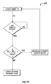
- Fig. 4 shows a flow chart illustrating a control algorithm 200 for regulating the application of energy to tissue, according to one embodiment of the present invention.
- algorithm 200 may be a software application residing in the memory 26 and executable by the controller 24 (e.g., via the microprocessor 25).
- the control algorithm defines a state variable (SV) to express a real-time value of one or more physical properties of the tissue undergoing ablation (e.g., tissue impedance, voltage across tissue, current through tissue) and/or one or more electrical properties related to the applied energy (e.g., amplitude and/or phase of power applied to tissue, etc.).
- the SV may be defined in any one or more so-called “states”.
- the SV may represent the real-time state of tissue resistance as being either "decreasing" or "rising”.
- the algorithm 200 initially defines the SV as decreasing and increases the application of energy to tissue (e.g., the controller 24 increases the output of the generator 20). Subsequently, the control algorithm 200 enters a switch loop 210 wherein the algorithm 200 continuously monitors the SV to be in any one of two states (e.g., decreasing or rising). Based on the detected state of the SV, the algorithm 200 switches between two control loops to control the application of energy to tissue.
- the algorithm 200 enters one of two control loops 220 and 230 to correspond to decreasing and rising states of the SV, respectively, as detected by the algorithm 200 via the switch loop 210. More specifically, the algorithm 200 enters a decreasing case control loop 220 if the switch loop 210 detects the state of the SV as decreasing. Upon entering control loop 220, the algorithm 200 continuously detects (e.g., via the sensor module 22) the slope of the control curve (e.g., the impedance vs. temperature curve of Fig. 3 ). If the detected slope of the control curve is negative, the algorithm 200 increases the application of energy to tissue (e.g., the controller 24 increases the output of the generator 20) and subsequently defines the SV as decreasing. In this manner, the decreasing case control loop 220 is repeated as long as the SV is defined as decreasing and the slope of the control curve is negative.
- the slope of the control curve e.g., the impedance vs. temperature curve of Fig. 3
- the algorithm 200 decreases the application of energy to tissue and subsequently defines the SV as rising. In this manner, the switch loop 210 detects the SV as rising and, thus, triggers the algorithm 200 to enter a rising case control loop 230.
- the algorithm 200 Upon entering the rising case control loop 230, the algorithm 200 continuously detects the slope of the control curve.
- the rising case control loop 230 is configured such that the response to the detected slope of the control curve is directly opposite to that of the decreasing case control loop 220. More specifically, if the detected slope of the control curve is negative during the rising case control loop 230, the algorithm 200 continues to decrease the application of energy to tissue (e.g., the controller 24 further decreases the output of the generator 20) and subsequently defines the SV as decreasing. Continuing to decrease the application of energy to tissue in this scenario allows the algorithm 200 to effectively track the optimal point on the control curve (e.g., lowest possible tissue impedance as a function of temperature).
- the algorithm 200 increases the application of energy to tissue and subsequently defines the SV as decreasing. Increasing the application of energy to tissue in this scenario allows the algorithm 200 to effectively deliver the maximum energy to tissue.
- the SV is reset to decreasing such that the algorithm 200 enters or re-enters the decreasing case control loop 220. In this way, the algorithm 200 aggressively applies energy to tissue to achieve maximal tissue heating while tracking the optimal point on the control curve (e.g., the lowest possible tissue impedance).
- the decreasing case control loop 220 recognizes that a slope detected as negative corresponds to the tissue impedance as decreasing and, thus, the algorithm 200 increases the application of energy to tissue accordingly and re-enters the decreasing case control loop 220. Conversely, the decreasing case control loop 220 recognizes that a slope detected as not negative corresponds to the tissue impedance as rising and, thus, the algorithm 200 decreases the application of energy to tissue accordingly and enters the rising case control loop 230.
- a tissue impedance vs. temperature curve e.g., Fig. 3
- the rising case control loop 230 recognizes that a slope detected as negative corresponds to the tissue impedance as decreasing and, thus, the algorithm 200 further decreases the application of energy to tissue to ensure the algorithm 200 finds the lowest possible tissue impedance. Conversely, the rising case control loop 230 recognizes that a slope detected as not negative corresponds to the tissue impedance as not changing or continuing to rise and, thus, the algorithm 200 increases the application of energy to tissue to ensure that the maximum energy is delivered to tissue.
- Fig. 4B shows a flow chart illustrating an alternative algorithm 300 according to according to the invention.
- the algorithm 300 operates similarly to the algorithm 200 illustrated in Fig. 4A and is only described to the extent necessary to illustrate the differences between the embodiments.
- the algorithm 300 utilizes the identical initialization as that of the algorithm 200 illustrated in Fig. 4A .
- the algorithm 300 includes a switch loop 310 configured to switch between two control loops, namely, a decreasing case control loop 320 and a rising case control loop 330 corresponding to the SV being defined as decreasing and rising, respectively.
- the difference between the algorithms 200 and 300 lies in the respective rising case control loops 230 and 330.
- the algorithm 300 decreases the energy applied to tissue and maintains the SV as rising rather than reset to decreasing, as is the case in the algorithm 200 embodied in Fig. 4A .
- a tissue impedance vs. temperature curve e.g., Fig.
- the algorithm 300 Upon detection that the tissue impedance is not negative, the algorithm 300 increases the application of energy to tissue and resets the SV to decreasing.
- a high priority control loop may be layered over the algorithms 200 and 300 to run concurrently therewith.
- tissue properties e.g., impedance
- the high priority control loop monitors the control curve for the runaway state and adjusts the application of energy (e.g., the controller 24 decreases the output of the generator 20) accordingly. More specifically, the high priority loop interrupts the algorithm (e.g., algorithm 200 and 300) to check for the runaway state, and decreases the application of energy in the event that such a state is detected.
- an impedance vs. temperature curve Fig.
- the high priority loop continually interrogates whether tissue impedance is rising more than a pre-determined threshold value.
- the pre-determined threshold value may be pre-determined by the surgeon via the generator 20 input controls and/or reside in the memory 26 for execution by the microprocessor 25.
- energy application is regulated by the controller 24 pursuant to a closed loop control system 400 stored within the memory 26.
- the system 400 continuously monitors tissue impedance as an indicator of tissue conductance and automatically adjusts output to create the lowest possible tissue impedance and/or the highest possible tissue conductance.
- the system 400 processes and stores a baseline impedance Z BASE determined by the sensor 24.
- the system 400 determines deviations in average tissue impedance from the baseline impedance Z BASE as a function of time and adjusts generator 20 output in response to such deviations. This allows peak tissue conductance to be maintained independent of tissue changes, variations in generator 20 output, and device accessory selection.
- the system 400 continually interrogates whether detected impedance has risen above a threshold value, and reduces generator output in response to any such threshold breaches. Finally, the system 400 may commence a treatment termination sequence upon detection of specific tissue conditions which indicate a completed treatment. Treatment completion may be indicated by an equilibrium between the level of energy applied to the tissue (e.g., via the forceps 10) and the level of energy dissipated from the tissue. Based on this equilibrium, the system 400 determines that the detected tissue impedance has achieved its lowest sustainable level and has remained at that level without change for a substantial amount of time.
- the closed loop control system 400 of the present disclosure provides continual control of the power supply 27 and/or the output stage 28 ( Fig. 2 ) in response to so-called "sensed" physical or electrical properties at the surgical site and/or proximate the output stage 28.
- the controller 24 may be provided with and/or in operative communication with an inner loop control module 402 and an outer loop control module 404 through which various priority tasks (e.g., loops) may be executed.
- the inner and outer loop control modules 402, 404 may be software modules executable by the microprocessor 25 of the controller 24 ( Fig. 2 ) and both may receive signals generated by the sensor module 22.
- the inner and outer loop control modules 402, 404 continually receive real-time sensed values, such as current I and voltage V, from the sensor module 22 as well as a time t.
- the modules 402, 404 perform calculations on the sensed values to derive additional real-time values, such as power P and impedance Z.
- additional real-time values such as power P and impedance Z.
- Fig. 6A shows a normal priority task 410 controlled by the inner loop control module 402 for automatic power adjustment to achieve peak conductance.
- the normal priority task 410 adjusts the power output by the generator 20 to continuously achieve peak tissue conductance (i.e., lowest tissue impedance) irrespective of changes to tissue (e.g., thickness, bubble formation, temperature, etc.), variations in generator output (e.g., manual adjustment of generator output power), and device and/or accessory selection (e.g., monopolar device, bipolar forceps, etc.).
- the inner loop control module 402 utilizes the normal priority task 410 to continuously monitor average tissue impedance over a period of time (e.g., a dZ AVE /dt waveform) as an indicator of tissue conductance since tissue conductance is inversely proportional to tissue impedance. The module 402 then automatically adjusts the output power of the generator 20 to provide the lowest possible tissue impedance and, thus, the highest possible tissue conductance.
- a period of time e.g., a dZ AVE /dt waveform
- an initial increase of the output power of the generator 20 is made over the duration of a first sample window of time (e.g., a user-defined time delay).
- the sensor module 22 determines a first slope of the average impedance waveform in response to the initial increase in output power of the generator 20.
- a second adjustment is made to the power output by the generator 20 and a second slope of the average impedance waveform is determined. If the second slope of the average impedance waveform is substantially the same as the first slope of the average impedance waveform, a third adjustment to the output power of the generator 20 is made. In this scenario, the second adjustment made to the power output by the generator 20 is a "reverse" adjustment to that of the first adjustment made to the power output by the generator 20.
- a host processor e.g., microprocessor 5
- the normal priority task 410 to monitor changes in average impedance as a function of time (e.g., dz/dt). More specifically, an initial increase ⁇ P i in output power of the generator 20 is made during time delay t1 while the sensor module 22 continuously monitors a first sampled average tissue impedance Z1 AVE to detect changes therein in response to the initial increase ⁇ P i in output power of the generator 20 as a function of time delay t1.
- the change in Z1AV E may be embodied as a waveform interpreted by the inner loop control module 402 which represents the first average impedance Z1 AVE as a function of time delay t1 (e.g., dZ1 AVE dt1).
- the normal priority task 410 may monitor the slope of the impedance waveform as an indication of changes in average tissue impedance over a sample window of time.
- the time delay t1 may be up to four (4) seconds during which the initial increase ⁇ P i in output power of the generator 20 is made at a rate of twenty (20) watts per second. In this configuration, the output power of the generator 20 may be gradually increased to eighty watts (80) over the duration of the time delay t1.
- the controller 24 makes a first adjustment ⁇ P 1 to increase the power output over the duration of a second time delay "t2."
- the second time delay t2 may be up to four (4) seconds to allow the sensor module 22 to record a sufficient sample of data related to changes in tissue impedance.
- the controller 24 makes a second adjustment ⁇ P 2 to decrease the power output over the duration of the second time delay t2.
- the controller 24 makes the second adjustment ⁇ P 2 to decrease the power output over the duration of the second time delay t2, the sensor module 22 continuously monitors for changes in a second sampled average tissue impedance Z2 AVE .
- the second adjustment ⁇ P 2 may be as much as a five (5) watt decrease over the duration of the second time delay t2.
- the controller 24 makes a third adjustment ⁇ P 3 to increase the power output by the generator 20 over the duration of a third time delay "t3.”
- the normal priority task 410 is thereafter repeated.
- the controller 24 makes a fourth adjustment ⁇ P 4 to decrease the power output over the duration of the third time delay t3, and the normal priority task 410 is repeated.
- the normal priority task 410 performs a reverse adjustment of power output by the generator 20 over the duration of the third time delay t3 relative to the adjustment made over the duration of the second time delay t2 in response to the same direction of the change (e.g., same slope direction) in the average tissue impedance as detected by the controller 24 during the first time delay t1. That is, over the duration of the first time delay t1, if the first average tissue impedance Z1 AVE either increases or is unchanged in response to the initial increase ⁇ P i in power output the controller 24 makes the second adjustment ⁇ P 2 to decrease the power output over the duration of the second time delay t2.
- the controller 24 makes the third adjustment ⁇ P 3 to increase the power output over the duration of the third time delay t3. It is in this manner that the normal priority task 410 operates to control the power output by the generator 20 to achieve the highest possible tissue conductance and, thus, the lowest possible tissue impedance throughout the duration of a given procedure.
- the duration of the time delays t1, t2, t3, the amount of the power adjustments ⁇ P i , ⁇ P 1 , ⁇ P 2 , ⁇ P 3 , ⁇ P 4 , the rate at which the power adjustments ⁇ P i , ⁇ P 1 , ⁇ P 2 , ⁇ P 3 , ⁇ P 4 are made, and the maximum level to which the power output may be increased by ⁇ P i may be pre-determined by the user via the user inputs of the generator 20 and/or a software-based user interface, as will be discussed in further detail below.
- the outer loop control module 404 is layered over the inner loop control module 402 and runs concurrently therewith to provide additional control of the generator 20 to reach a desired output value or effect.
- the outer loop control module 404 utilizes a high priority task 420 to prevent tissue properties (e.g., impedance) from rising and/or falling outside the peak conductance range or a so-called "run-away state.”
- tissue properties e.g., impedance
- the sensor module 22 Upon activation, the sensor module 22 records a baseline impedance value Z BASE and transmits this value to the controller 24 for storing in the memory 26.
- the high priority task 420 processes the base impedance Z BASE stored in the memory 26 and continually monitors deviations in average tissue impedance Z AVE from the base impedance Z BASE as a function of time (e.g., a dz/dt waveform).
- the high priority task 420 compares the deviations to a threshold impedance value Z MAX , and automatically adjusts the output power of the generator 20 to counteract increases in the average impedance Z AVE that breach the threshold value Z MAX . That is, if a rise in average tissue impedance Z AVE over a sample window of time exceeds the threshold value Z MAX , the output power of the generator 20 is decreased by the controller 24.
- the threshold impedance value Z MAX may be determined by detecting a change in average impedance Z AVE over some period of time (e.g., an average change of 20 ohms over seven seconds), and comparing this change in average impedance Z AVE to the base impedance value Z BASE stored in memory 26.
- Fig. 6B shows the high priority task 420 controlled by the outer loop control module 404 for automatic power adjustment based on detected rises in average tissue impedance Z AVE that exceed the threshold impedance value Z MAX .
- the high priority task 420 is layered over the normal priority task 410 and runs concurrently therewith.
- the outer loop control module 404 utilizes the high priority task 420 to continuously monitor average tissue impedance as a function of time (e.g., a dz/dt waveform).
- the average tissue impedance may be an average peak impedance Z PEAK sampled over a substantially short period of time, e.g., 0.05 seconds.
- the controller 24 makes a fifth adjustment ⁇ P 5 to decrease the power output.
- a predetermined impedance value ⁇ P e.g., 20 ohms nominal
- the output level of the generator 20 at which the base impedance Z BASE will be determined, the impedance value ⁇ P, and the fifth adjustment ⁇ P 5 may be pre-determined by the user via the user inputs of the generator 20 and/or a software-based user interface, as will be discussed in further detail below.
- the outer loop control module 404 may utilize a low priority task 430 to determine when to terminate the power output by the generator 20 to end a given tissue treatment.
- the low priority task 430 is based on a determination that an equilibrium exists between the energy applied by the generator 20 (e.g., via the forceps 10) and the energy that is dissipated from the tissue site.
- the low priority task 430 may determine whether average tissue impedance has achieved its lowest sustainable level and remains at that level without substantial change for a substantial period of time.
- the low priority task 430 is layered over the normal priority task 410 and runs concurrently therewith.
- the outer loop control module 404 utilizes the low priority task 430 to continuously monitor average tissue impedance as a function of time (e.g., over the duration of a given procedure).
- the controller 24 continually receives a current average tissue impedance value Z AVEn from the sensor module 22.
- the low priority task 430 compares the current tissue impedance value Z AVEn to a historical tissue impedance value Z AVEn-1 stored in the memory 26 from the previous iteration through the low priority task 430.
- the current average tissue impedance value Z AVEn is stored in the memory 26 as the historical tissue impedance value Z AVEn-1 .
- the low priority task 430 monitors average tissue impedance for certain criteria that may indicate that a given treatment is complete and, thus, the power output may be terminated. This criteria may include determining that the current tissue impedance value Z AVEn is substantially equivalent to the historical tissue impedance value Z AVEn-1 stored in the memory 26 over the duration of a fifth time delay "t5" after the generator 20 is activated.
- the generator 20 may continue to output power over the duration of a sixth time delay "t6." Following the time delay t6, the generator 20 is turned “off” and the procedure is terminated.
- the low priority task 430 the power output may be terminated immediately by the controller 24 upon the expiration of the fifth time delay t5. Alternatively, output may be adjusted by the controller 24 to a predetermined level by the user (e.g., via the user inputs of the generator 20 and/or a software-based user interface).
- the duration of the time delays t4, t5, t6 may be pre-determined by the user via the user inputs of the generator 20 and/or a software-based user interface, as will be discussed in further detail below.
- Fig. 7A illustrates a software system 500 embedded in the memory 26 and executed by the microprocessor 25 which utilizes a normal priority task 510, a high priority task 520, and low priority task 530 to control generator 20 output based on changes in average tissue impedance as a function of time.
- Each task 510, 520, 530 processes averaged impedance data received from a plurality of single pole recursive impedance filters that continuously filter and/or average tissue impedance data sensed by the sensor module 22.
- impedance filters Zf1 - Zf8 are used in conjunction with the software system 500.
- Each of the impedance filters Zf1 - Zf8 may be formatted for use with the following data averaging formula (1):
- ZfX n Zin * ⁇ A + ZfX n - 1 * ⁇ B
- a and B are dependent on a time constant and may be specified by the user, via the input controls of the generator 20, for each particular impedance filter ZfX.
- the sample rate may also be specified by the user for calculating the number of samples.
- Zin is the new impedance value (e.g., Z RMS ) just calculated
- ZfX n-1 is the filtered impedance, for the filter number specified by X, from the previous iteration through the loop
- ZfX n is the new filtered impedance value for the filter number specified by X.
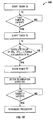
- the normal priority task 510 is made up of three states, namely, an initializing state 550, a run state 560, and a peak state 570.
- the initializing state 550 the ablation procedure is activated (e.g., by pressing of a foot pedal or handswitch) and a host processor (e.g., microprocessor 5) activates the software system 500 for monitoring the plurality of impedance filters Zf1 - Zf8.
- a first timer "T1" is initialized to run concurrently with the initializing state 550.
- the first timer T1 may be set by the user (e.g., via the user inputs of the generator 20 and/or a software-based user interface) as the amount of time the software system 500 waits during the state 550, after initial activation, before interrogating the plurality of impedance filters, as will be discussed in further detail below.
- the generator 20 operates at a baseline level of power P BASE . It is at this baseline level of power P BASE that the sensor module 22 records a baseline impedance Z BASE and transmits this value to the controller 24 for storing in the memory 26. Once the baseline impedance Z BASE has been recorded, the power output by the generator 20 is ramped by the controller 24 to an initial level P INIT . The user may be able to specify (e.g., via the user inputs of the generator 20 and/or a software-based user interface) the rate at which the power output by the generator 20 is ramped as well as a maximum level of power P MAX to which the generator 20 may be ramped. The power output by the generator 20 is ramped by the controller 24 until either the first timer T1 expires or P MAX is reached.
- the normal priority task 510 Upon expiration of the first timer T1, the normal priority task 510 stores the baseline impedance Z BASE into the memory 26 as impedance value Zf1 n-1 and enters the run state 560. Once the run state 560 is initialized, the normal priority task 510 starts a second timer "T2" which runs concurrently with the run state 560.
- the second timer T2 may be predetermined by the user (e.g., via the user inputs of the generator 20 and/or a software-based user interface) as the amount of time the normal priority task 510 operates in the run state 560 prior to interrogating the plurality of impedance filters for average impedance data.
- the software system 500 immediately calculates the difference between the current filtered impedance Zf2 n and the previous filtered impedance Zf1 n-1 and compares this difference to a first impedance reference Zdelta1.
- the first impedance reference, Zdelta1 is the amount of change from the previous filtered impedance Zf1 n-1 to the current filtered impedance Zf2 n which is a threshold for triggering an increase or decrease in power output by the generator 20.
- the impedance reference Zdelta1 may be predetermined (e.g., via the user inputs of the generator 20 and/or a software-based user interface) by the user.
- the controller 24 makes a first adjustment P1 to increase the power output by the generator 20 and the normal priority task 510 reenters the run state 560.
- the software system 500 restarts the second timer T2 and waits for the second timer to expire before interrogating impedance filters Zf1 and Zf2 for filtered impedance data.
- the controller 24 makes a second adjustment P2 to decrease the power output by the generator 20 and the normal priority task 510 enters the peak state 570.
- the software system 500 starts a third timer "T3", as will be discussed in further detail below.
- the duration of the third timer T3, the amount of the first and second power adjustments P1, P2 may be pre-determined by the user via the user inputs of the generator 20 and/or a software-based user interface, as will be discussed in further detail below.
- the software system 500 Upon exiting the run state 560, the software system 500 stores the current filtered impedance value Zf1 n into the memory 26 as the previous filtered impedance Zf1 n-1 , and stores the filtered impedance Zf3n into the memory 26 as the previous filtered impedance Zf3 n-1 . That is, prior to the exiting of the run state 560, the current filtered impedances Zf1 n and Zf3 n determined during the present iteration through the run state 560 become the respective previous filtered impedances Zf1 n-1 and Zf3 n-1 once the run state 560 is reentered (i.e., once the present iteration through the run state 560 becomes the previous iteration through the run state).
- the third timer T3 is initialized by the software system 500 to coincide with the initialization of the peak state 570 and to run concurrently therewith. Once the third timer T3 expires, the software system 500 calculates the difference between the current filtered impedance Zf4 n and the previous filtered impedance Zf3 n-1 and compares this difference to a second impedance reference Zdelta2.
- the second impedance reference, Zdelta2 is the amount of change from the previous filtered impedance Zf3 n-1 to the current filtered impedance Zf4 n which is a threshold fro triggering an increase or decrease in power output.
- the controller 24 makes a third adjustment P3 to decrease the power output and the normal priority task 510 reenters the run state 560 and the software system 500 restarts the second timer T2.
- the controller 24 makes a fourth adjustment P4 to increase the power output and the normal priority task 510 reenters the run state 560 and the software system 500 restarts the second timer T2.
- the second impedance reference Zdelta2 and the third and fourth power adjustments P3, P4 may be pre-determined by the user via the user inputs of the generator 20 and/or a software-based user interface, as will be discussed in further detail below.
- the software system 500 Upon exiting the peak state 570, the software system 500 stores the current filtered impedance Zf1 n into the memory 26 as the previous filtered impedance Zf1 n-1 and stores the current filtered impedance Zf3 n into the memory 26 as the previous filtered impedance Zf3 n-1 .
- the duration of the first, second, and third timers T1, T2, T3 and the amount of the first and second power adjustments P1, P2 may be pre-determined by the user via the user inputs of the generator 20 and/or a software-based user interface, as will be discussed in further detail below.
- the high priority task 520 is layered over the normal priority task 510 and runs concurrently therewith to provide additional control of the generator 20 to reach a desired output value or effect.
- a fourth timer "T4" is initialized by the software system 500 to coincide with the initialization of the high priority task 520 and to run concurrently therewith. Once the fourth timer T4 expires, the software system 500 calculates the difference between the current filtered impedance Zf6 n and the current filtered impedance Zf5 n and compares this difference to a third impedance reference Zdelta3.
- the third impedance reference, Zdelta3 is the amount of change from the current filtered impedance Zf5 n to the current filtered impedance Zf6 n which is a threshold for triggering a decrease in power output.
- the third impedance reference Zdelta3 operates in a threshold capacity to prevent dangerous conditions such as a run-away state that may arise and lead to continued power increases and impedance rises.
- the controller 24 makes a fifth adjustment P5 to decrease the power output and the software system 500 reenters the high priority task 520 and restarts the fourth timer T4.
- the software system 500 enters the normal priority task 510.
- the normal priority task 510 is only entered from the high priority task 520 if the third reference impedance Zdelta3 threshold is not equaled or exceeded.
- the duration of the fourth timer T4, the third impedance reference Zdelta3, and the amount of the fifth power adjustment P5 may be pre-determined by the user via the user inputs of the generator 20 and/or a software-based user interface, as will be discussed in further detail below.
- the low priority task 530 is layered over the normal priority task 510 and runs concurrently with both the high priority task 520 and the normal priority task 510 to provide additional control of the generator 20 to terminate the procedure once a desired output value or effect has been achieved.
- a fifth timer "T5" is initialized to coincide with the initialization of the vessel sealing procedure (e.g., by pressing a foot pedal or handswitch), and to run concurrently therewith. Once the fifth timer T5 expires, the software system 500 continuously interrogates whether particular impedance conditions indicative of a desired tissue effect exist for the duration of a sixth timer "T6"and, if such criteria is met, accordingly initiates a process to terminate the power output.
- the software system 500 calculates the difference between the current filtered impedance Zf8 n and the current filtered impedance Zf7 n and compares this difference to a fourth impedance reference Zdelta4.
- the fourth impedance reference Zdelta4 is the amount of change from the current filtered impedance Zf7 n to the current filtered impedance Zf8 n that initiates a seventh timer "T7," the expiration of which triggers the generator 20 to shut off and the procedure to be terminated.
- the seventh timer T7 is initialized.
- a termination state 535 of the low priority task 530 is triggered to provide for a plurality of options which allow the user to predetermine (e.g., via the user inputs of the generator 20) how the generator 20 will behave once the condition discussed above is satisfied for the duration of the sixth timer T6.
- Options available to the user with respect to the termination state 535 may include allowing the generator 20 to operate at it's current output level for the duration of the seventh timer T7, specifying an output level at which generator 20 is to operate for the duration of the seventh timer T7, and continuing with the low priority task 530 until the seventh timer T7 expires.
- the software system 500 continues to execute the low priority task 530 concurrently with the high priority and normal priority tasks 520 and 530.
- the duration of the fifth, sixth, and seventh timers T5, T6, T7 and the fourth impedance reference Zdelta4 may be pre-determined by the user via the user inputs of the generator 20 and/or a software-based user interface, as will be discussed in further detail below.
- An eighth timer T8 may be specified by the user (e.g., via the user inputs of the generator 20 and/or a software-based user interface) as a "master" timer (i.e., total procedure time) for the operation of the generator 20 in a given procedure. In this configuration, the generator 20 is shut off upon the expiration of the procedure timer T8 regardless of whether or not the termination state 535 is entered.
- a software-based graphical user interface 600 is shown for use with the software system 500.
- the interface 600 may include a plurality of editable parameters to allow the user to provide specific values (e.g., via the user inputs of the generator 20) for controlling the power output by the generator 20 via the software system 500.
- the interface 600 allows the user to test and/or validate the software system 500 of the present disclosure.
- the interface 600 may be organized by priority level and/or task level including a normal priority interface 610, a high priority interface 620, and a low priority interface 630, as shown in Fig. 8 .
- a control interface 640 may be provided to allow the user to specify various control parameters such as, for example, the procedure time (e.g., the eighth timer T8) and the file path and/or location of a file to be executed by the software system 500, etc.
- the normal priority interface 610 is configured to be edited by the user to provide specific parameters for predetermining the behavior of the normal priority task 510 during a given procedure.
- the normal priority interface 610 may be divided into three sub-interfaces, namely, an initialization state interface 650, a run state interface 660, and a peak state interface 670, to coincide with the three states 550, 560, and 570 of the normal priority task 510, respectively.
- the interfaces 650, 660, and 670 may be edited by the user to provide specific parameters for further predetermining the behavior of the normal priority task 510 during a given procedure.
- the user may be able to specify parameters related to the initialization state 550 of the normal priority task 510, such as the duration of the first timer T1 and power levels of P BASE , P INIT , P RATE , and P MAX .
- the user may be able to specify parameters related to the run state 560 of the normal priority task 510, such as the duration of the second timer T2, the first impedance reference Zdelta1, and the amount of the first and second power adjustments P1, P2.
- the user may be able to specify parameters related to the peak state 570 of the normal priority task 510, such as the duration of the third timer T3, the second impedance reference Zdelta2, and the amount of the third and fourth power adjustments P3 and P4.
- the high priority interface 620 is configured to be edited by the user to provide specific parameters for predetermining the behavior of the high priority task 520 during a given procedure.
- the user may be able to specify parameters such as the duration of the fourth timer T4, the third impedance reference Zdelta3, and the fifth power adjustment P5.
- the low priority interface 630 is configured to be edited by the user to provide specific parameters for predetermining the behavior of the low priority task 530 during a given procedure.
- the user may be able to specify parameters such as the duration of the fifth, sixth, and seventh timers T5, T6, T7 and impedance reference Zdelata4.
- the termination state 535 of the low priority task 530 the user may be able to choose from a menu of options (not explicitly shown) to select how the generator 20 will behave over the duration of the seventh timer T7 once the termination state 535 is entered (e.g., continue current output level, adjust to a predetermined output level, shut off upon the expiration of the seventh timer T7, etc.).
Claims (2)
- Elektrochirurgischer Generator (20), mit:einem Hochfrequenzausgang (28), der eingerichtet ist, Energie auszugeben, die auf Gewebe angewandt wird;einem Sensormodul (22), das eingerichtet ist, Gewebeeigenschaften zu detektieren, einschließlich einer Gewebeimpedanz und einer Gewebetemperatur;einem Regler (24), der eingerichtet ist, dem Hochfrequenzausgang zu signalisieren, die auf ein Gewebe angewandte Energie in einer Anfangsrichtung einzustellen und eine Zustandsvariable, SV, zu bestimmen, die einen abnehmenden oder aufsteigenden Zustand der Gewebeimpedanz wiedergibt, wobei der Regler des Weiteren eingerichtet ist, die SV anfangs als abnehmend zu definieren und die Anwendung einer Energie auf das Gewebe zu erhöhen und nachfolgend in eine Schaltschleife (210) einzutreten, in der der Regler eingerichtet ist, die SV kontinuierlich zu überwachen, um in einem abnehmenden oder ansteigenden Zustand zu sein, und basierend auf dem detektierten Zustand der SV der Regler eingerichtet ist, zwischen zwei Regelungsschleifen (220, 230) umzuschalten, um die Anwendung von Energie auf ein Gewebe zu regeln, wobei der Regler eingerichtet ist, in eine Abnahmefall-Regelungsschleife (220) einzutreten, wenn die Schaltschleife den Zustand der SV als abnehmend detektiert, wodurch beim Eintritt in die Abnahmefall-Regelungsschleife der Regler eingerichtet ist, um über das Sensormodul kontinuierlich die Steigung einer Impedanz-Temperatur-Regelungskurve zu detektieren, und wenn die detektierte Steigung der Regelungskurve negativ ist, was einer abnehmenden Gewebeimpedanz entspricht, der Regler die Anwendung von Energie auf ein Gewebe erhöht und danach die SV als abnehmend definiert und wenn die detektierte Steigung der Regelungskurve nicht negativ ist, der Regler eingerichtet ist, die Anwendung von Energie auf ein Gewebe zu vermindern und danach die SV als ansteigend zu definieren, wobei die Regelungsschleife nach dem Definieren der SV wieder in die Schaltschleife eintritt, und wobei der Regler eingerichtet ist, in eine Anstiegsfall-Regelungsschleife (230) einzutreten, wenn die Schaltschleife den Zustand der SV als ansteigend detektiert, wodurch beim Eintreten in die Anstiegsfall-Regelungsschleife der Regler eingerichtet ist, die Steigung der Regelungskurve kontinuierlich zu detektieren, wobei, wenn die detektierte Steigung der Regelungskurve während der Anstiegsfall-Regelungskurve negativ ist, der Regler eingerichtet ist, die Anwendung von Energie auf ein Gewebe zu vermindern und nachfolgend die SV als ansteigend oder abnehmend zu definieren, und wenn die detektierte Steigung der Regelungskurve nicht negativ ist, der Regler eingerichtet ist, die Anwendung von Energie auf ein Gewebe zu erhöhen und nachfolgend die SV als abnehmend zu definieren, und wobei die Regelungsschleife nach dem Definieren der SV wieder in die Schaltschleife eintritt.
- Generator gemäß Anspruch 1, bei dem der Regler des Weiteren eingerichtet ist, eine Änderungsrate der Regelungskurve zu detektieren und die auf ein Gewebe angewandte Energie einzustellen, wenn die detektierte Änderungsrate einen festgelegten Wert überschreitet.
Applications Claiming Priority (1)
| Application Number | Priority Date | Filing Date | Title |
|---|---|---|---|
| US12/351,935 US8167875B2 (en) | 2009-01-12 | 2009-01-12 | Energy delivery algorithm for medical devices |
Publications (2)
| Publication Number | Publication Date |
|---|---|
| EP2213255A1 EP2213255A1 (de) | 2010-08-04 |
| EP2213255B1 true EP2213255B1 (de) | 2012-03-07 |
Family
ID=42174400
Family Applications (1)
| Application Number | Title | Priority Date | Filing Date |
|---|---|---|---|
| EP10150563A Active EP2213255B1 (de) | 2009-01-12 | 2010-01-12 | Energieabgabealgorithmus für medizinische Vorrichtungen |
Country Status (7)
| Country | Link |
|---|---|
| US (1) | US8167875B2 (de) |
| EP (1) | EP2213255B1 (de) |
| JP (1) | JP5537959B2 (de) |
| AT (1) | ATE547989T1 (de) |
| AU (1) | AU2010200113B8 (de) |
| CA (1) | CA2689908A1 (de) |
| ES (1) | ES2383502T3 (de) |
Cited By (1)
| Publication number | Priority date | Publication date | Assignee | Title |
|---|---|---|---|---|
| EP2805682A1 (de) | 2013-05-24 | 2014-11-26 | Erbe Elektromedizin GmbH | Koagulationseinrichtung mit Energiesteuerung |
Families Citing this family (36)
| Publication number | Priority date | Publication date | Assignee | Title |
|---|---|---|---|---|
| US7137980B2 (en) | 1998-10-23 | 2006-11-21 | Sherwood Services Ag | Method and system for controlling output of RF medical generator |
| US7811282B2 (en) | 2000-03-06 | 2010-10-12 | Salient Surgical Technologies, Inc. | Fluid-assisted electrosurgical devices, electrosurgical unit with pump and methods of use thereof |
| US7044948B2 (en) | 2002-12-10 | 2006-05-16 | Sherwood Services Ag | Circuit for controlling arc energy from an electrosurgical generator |
| EP1617776B1 (de) | 2003-05-01 | 2015-09-02 | Covidien AG | System zur programmierung und kontrolle eines elektrochirurgischen generatorsystems |
| WO2005050151A1 (en) | 2003-10-23 | 2005-06-02 | Sherwood Services Ag | Thermocouple measurement circuit |
| US7396336B2 (en) | 2003-10-30 | 2008-07-08 | Sherwood Services Ag | Switched resonant ultrasonic power amplifier system |
| US7947039B2 (en) | 2005-12-12 | 2011-05-24 | Covidien Ag | Laparoscopic apparatus for performing electrosurgical procedures |
| CA2574934C (en) | 2006-01-24 | 2015-12-29 | Sherwood Services Ag | System and method for closed loop monitoring of monopolar electrosurgical apparatus |
| US7651492B2 (en) | 2006-04-24 | 2010-01-26 | Covidien Ag | Arc based adaptive control system for an electrosurgical unit |
| US7794457B2 (en) | 2006-09-28 | 2010-09-14 | Covidien Ag | Transformer for RF voltage sensing |
| US8409186B2 (en) | 2008-03-13 | 2013-04-02 | Covidien Lp | Crest factor enhancement in electrosurgical generators |
| US8257349B2 (en) | 2008-03-28 | 2012-09-04 | Tyco Healthcare Group Lp | Electrosurgical apparatus with predictive RF source control |
| US8403924B2 (en) | 2008-09-03 | 2013-03-26 | Vivant Medical, Inc. | Shielding for an isolation apparatus used in a microwave generator |
| US8377053B2 (en) | 2008-09-05 | 2013-02-19 | Covidien Lp | Electrosurgical apparatus with high speed energy recovery |
| US8287529B2 (en) | 2008-09-05 | 2012-10-16 | Tyco Healthcare Group Lp | Electrosurgical apparatus with high speed energy recovery |
| US8262652B2 (en) | 2009-01-12 | 2012-09-11 | Tyco Healthcare Group Lp | Imaginary impedance process monitoring and intelligent shut-off |
| US9522039B2 (en) | 2009-03-11 | 2016-12-20 | Covidien Lp | Crest factor enhancement in electrosurgical generators |
| US8932282B2 (en) * | 2009-08-03 | 2015-01-13 | Covidien Lp | Power level transitioning in a surgical instrument |
| US8685015B2 (en) * | 2009-09-24 | 2014-04-01 | Covidien Lp | System and method for multi-pole phase-shifted radio frequency application |
| US8377054B2 (en) * | 2009-09-24 | 2013-02-19 | Covidien Lp | Automatic control circuit for use in an electrosurgical generator |
| US8610501B2 (en) | 2009-11-16 | 2013-12-17 | Covidien Lp | Class resonant-H electrosurgical generators |
| US10039588B2 (en) | 2009-12-16 | 2018-08-07 | Covidien Lp | System and method for tissue sealing |
| US8454590B2 (en) * | 2010-02-26 | 2013-06-04 | Covidien Lp | Enhanced lossless current sense circuit |
| US8636730B2 (en) * | 2010-07-12 | 2014-01-28 | Covidien Lp | Polarity control of electrosurgical generator |
| PL2540244T3 (pl) * | 2011-06-30 | 2017-11-30 | Erbe Elektromedizin Gmbh | Urządzenie do zoptymalizowanej koagulacji tkanki biologicznej |
| US9498182B2 (en) | 2012-05-22 | 2016-11-22 | Covidien Lp | Systems and methods for planning and navigation |
| US8750568B2 (en) * | 2012-05-22 | 2014-06-10 | Covidien Lp | System and method for conformal ablation planning |
| US9439622B2 (en) | 2012-05-22 | 2016-09-13 | Covidien Lp | Surgical navigation system |
| US9439623B2 (en) | 2012-05-22 | 2016-09-13 | Covidien Lp | Surgical planning system and navigation system |
| US9439627B2 (en) | 2012-05-22 | 2016-09-13 | Covidien Lp | Planning system and navigation system for an ablation procedure |
| US9872719B2 (en) | 2013-07-24 | 2018-01-23 | Covidien Lp | Systems and methods for generating electrosurgical energy using a multistage power converter |
| US9636165B2 (en) | 2013-07-29 | 2017-05-02 | Covidien Lp | Systems and methods for measuring tissue impedance through an electrosurgical cable |
| US10350423B2 (en) | 2016-02-04 | 2019-07-16 | Cardiac Pacemakers, Inc. | Delivery system with force sensor for leadless cardiac device |
| US11707329B2 (en) | 2018-08-10 | 2023-07-25 | Covidien Lp | Systems and methods for ablation visualization |
| WO2020096863A1 (en) * | 2018-11-07 | 2020-05-14 | Intuitive Surgical Operations, Inc. | Rf electrosurgical tissue sealing sytem and method |
| SG11202111518WA (en) | 2019-05-09 | 2021-11-29 | Gyrus Acmi Inc D/B/A Olympus Surgical Technologies America | Electrosurgical systems and methods |
Family Cites Families (98)
| Publication number | Priority date | Publication date | Assignee | Title |
|---|---|---|---|---|
| DE179607C (de) | 1906-11-12 | |||
| DE390937C (de) | 1922-10-13 | 1924-03-03 | Adolf Erb | Vorrichtung zur Innenbeheizung von Wannenoefen zum Haerten, Anlassen, Gluehen, Vergueten und Schmelzen |
| GB607850A (en) | 1946-04-01 | 1948-09-06 | William George Curwain | Electric connectors |
| GB702510A (en) | 1951-03-24 | 1954-01-20 | Foxboro Co | Improvements in temperature responsive instruments |
| GB855459A (en) | 1958-04-11 | 1960-11-30 | Keeler Optical Products Ltd | Improvements in or relating to electro-surgical apparatus |
| DE1099658B (de) | 1959-04-29 | 1961-02-16 | Siemens Reiniger Werke Ag | Selbsttaetige Einschaltvorrichtung fuer Hochfrequenzchirurgiegeraete |
| GB902775A (en) | 1959-05-16 | 1962-08-09 | Kathleen Zilla Rumble | Improvements in or relating to electrical plugs |
| FR1275415A (fr) | 1960-09-26 | 1961-11-10 | Dispositif détecteur de perturbations pour installations électriques, notamment d'électrochirurgie | |
| DE1139927B (de) | 1961-01-03 | 1962-11-22 | Friedrich Laber | Hochfrequenz-Chirurgiegeraet |
| DE1149832C2 (de) | 1961-02-25 | 1977-10-13 | Siemens AG, 1000 Berlin und 8000 München | Hochfrequenz-chirurgieapparat |
| FR1347865A (fr) | 1962-11-22 | 1964-01-04 | Perfectionnements aux appareils de diathermo-coagulation | |
| DE1439302B2 (de) | 1963-10-26 | 1971-05-19 | Siemens AG, 1000 Berlin u 8000 München | Hochfrequenz Chirurgiegerat |
| GB1480736A (en) | 1973-08-23 | 1977-07-20 | Matburn Ltd | Electrodiathermy apparatus |
| FR2251864A1 (en) | 1973-11-21 | 1975-06-13 | Termiflex Corp | Portable input and output unit for connection to a data processor - is basically a calculator with transmitter and receiver |
| DE2407559C3 (de) | 1974-02-16 | 1982-01-21 | Dornier System Gmbh, 7990 Friedrichshafen | Wärmesonde |
| US4237887A (en) | 1975-01-23 | 1980-12-09 | Valleylab, Inc. | Electrosurgical device |
| DE2504280C3 (de) | 1975-02-01 | 1980-08-28 | Hans Heinrich Prof. Dr. 8035 Gauting Meinke | Vorrichtung zum Schneiden und/oder Koagulieren menschlichen Gewebes mit Hochfrequenzstrom |
| CA1064581A (en) | 1975-06-02 | 1979-10-16 | Stephen W. Andrews | Pulse control circuit and method for electrosurgical units |
| DE2540968C2 (de) | 1975-09-13 | 1982-12-30 | Erbe Elektromedizin GmbH, 7400 Tübingen | Einrichtung zum Einschalten des Koagulationsstroms einer bipolaren Koagulationspinzette |
| US4094320A (en) | 1976-09-09 | 1978-06-13 | Valleylab, Inc. | Electrosurgical safety circuit and method of using same |
| FR2390968A1 (fr) | 1977-05-16 | 1978-12-15 | Skovajsa Joseph | Dispositif de traitement local d'un patient, notamment pour acupuncture ou auriculotherapie |
| SU727201A2 (ru) | 1977-11-02 | 1980-04-15 | Киевский Научно-Исследовательский Институт Нейрохирургии | Электрохирургический аппарат |
| US4200104A (en) | 1977-11-17 | 1980-04-29 | Valleylab, Inc. | Contact area measurement apparatus for use in electrosurgery |
| DE2803275C3 (de) | 1978-01-26 | 1980-09-25 | Aesculap-Werke Ag Vormals Jetter & Scheerer, 7200 Tuttlingen | Fernschalteinrichtung zum Schalten eines monopolaren HF-Chirurgiegerätes |
| DE2823291A1 (de) | 1978-05-27 | 1979-11-29 | Rainer Ing Grad Koch | Schaltung zur automatischen einschaltung des hochfrequenzstromes von hochfrequenz-koagulationsgeraeten |
| DE2946728A1 (de) | 1979-11-20 | 1981-05-27 | Erbe Elektromedizin GmbH & Co KG, 7400 Tübingen | Hochfrequenz-chirurgiegeraet |
| JPS5778844A (en) | 1980-11-04 | 1982-05-17 | Kogyo Gijutsuin | Lasre knife |
| DE3045996A1 (de) | 1980-12-05 | 1982-07-08 | Medic Eschmann Handelsgesellschaft für medizinische Instrumente mbH, 2000 Hamburg | Elektro-chirurgiegeraet |
| FR2502935B1 (fr) | 1981-03-31 | 1985-10-04 | Dolley Roger | Procede et dispositif de controle de la coagulation de tissus a l'aide d'un courant a haute frequence |
| DE3120102A1 (de) | 1981-05-20 | 1982-12-09 | F.L. Fischer GmbH & Co, 7800 Freiburg | Anordnung zur hochfrequenzkoagulation von eiweiss fuer chirurgische zwecke |
| FR2517953A1 (fr) | 1981-12-10 | 1983-06-17 | Alvar Electronic | Appareil diaphanometre et son procede d'utilisation |
| US4727874A (en) | 1984-09-10 | 1988-03-01 | C. R. Bard, Inc. | Electrosurgical generator with high-frequency pulse width modulated feedback power control |
| FR2573301B3 (fr) | 1984-11-16 | 1987-04-30 | Lamidey Gilles | Pince chirurgicale et son appareillage de commande et de controle |
| DE3510586A1 (de) | 1985-03-23 | 1986-10-02 | Erbe Elektromedizin GmbH, 7400 Tübingen | Kontrolleinrichtung fuer ein hochfrequenz-chirurgiegeraet |
| DE3604823C2 (de) | 1986-02-15 | 1995-06-01 | Lindenmeier Heinz | Hochfrequenzgenerator mit automatischer Leistungsregelung für die Hochfrequenzchirurgie |
| EP0246350A1 (de) | 1986-05-23 | 1987-11-25 | Erbe Elektromedizin GmbH. | Koagulationselektrode |
| US4931047A (en) | 1987-09-30 | 1990-06-05 | Cavitron, Inc. | Method and apparatus for providing enhanced tissue fragmentation and/or hemostasis |
| EP0325456B1 (de) | 1988-01-20 | 1995-12-27 | G2 Design Limited | Diathermiegerät |
| GB8801177D0 (en) | 1988-01-20 | 1988-02-17 | Goble N M | Diathermy unit |
| DE3904558C2 (de) | 1989-02-15 | 1997-09-18 | Lindenmeier Heinz | Automatisch leistungsgeregelter Hochfrequenzgenerator für die Hochfrequenz-Chirurgie |
| DE58908600D1 (de) | 1989-04-01 | 1994-12-08 | Erbe Elektromedizin | Einrichtung zur Überwachung der Applikation von Neutralelektroden bei der Hochfrequenzchirurgie. |
| DE3942998C2 (de) | 1989-12-27 | 1998-11-26 | Delma Elektro Med App | Elektrochirurgisches Hochfrequenzgerät |
| JPH0763482B2 (ja) * | 1992-01-28 | 1995-07-12 | アロカ株式会社 | 電気手術器 |
| DE4205213A1 (de) | 1992-02-20 | 1993-08-26 | Delma Elektro Med App | Hochfrequenzchirurgiegeraet |
| WO1994010922A1 (en) | 1992-11-13 | 1994-05-26 | Ep Technologies, Inc. | Cardial ablation systems using temperature monitoring |
| US5348554A (en) | 1992-12-01 | 1994-09-20 | Cardiac Pathways Corporation | Catheter for RF ablation with cooled electrode |
| DE4339049C2 (de) | 1993-11-16 | 2001-06-28 | Erbe Elektromedizin | Einrichtung zur Konfiguration chirurgischer Systeme |
| US6293942B1 (en) * | 1995-06-23 | 2001-09-25 | Gyrus Medical Limited | Electrosurgical generator method |
| US6186147B1 (en) | 1996-05-30 | 2001-02-13 | Nuvotek Limited | Method for electrosurgical tissue cutting and coagulation |
| US5931836A (en) | 1996-07-29 | 1999-08-03 | Olympus Optical Co., Ltd. | Electrosurgery apparatus and medical apparatus combined with the same |
| US6544260B1 (en) | 1996-08-20 | 2003-04-08 | Oratec Interventions, Inc. | Method for treating tissue in arthroscopic environment using precooling and apparatus for same |
| DE19643127A1 (de) | 1996-10-18 | 1998-04-23 | Berchtold Gmbh & Co Geb | Hochfrequenzchirurgiegerät und Verfahren zu dessen Betrieb |
| US5954719A (en) | 1996-12-11 | 1999-09-21 | Irvine Biomedical, Inc. | System for operating a RF ablation generator |
| DE19717411A1 (de) | 1997-04-25 | 1998-11-05 | Aesculap Ag & Co Kg | Verfahren und Vorrichtung zur Überwachung der thermischen Belastung des Gewebes eines Patienten |
| US5838558A (en) | 1997-05-19 | 1998-11-17 | Trw Inc. | Phase staggered full-bridge converter with soft-PWM switching |
| US6139546A (en) | 1997-10-06 | 2000-10-31 | Somnus Medical Technologies, Inc. | Linear power control with digital phase lock |
| US6080149A (en) | 1998-01-09 | 2000-06-27 | Radiotherapeutics, Corporation | Method and apparatus for monitoring solid tissue heating |
| US6537272B2 (en) | 1998-07-07 | 2003-03-25 | Medtronic, Inc. | Apparatus and method for creating, maintaining, and controlling a virtual electrode used for the ablation of tissue |
| US6123702A (en) | 1998-09-10 | 2000-09-26 | Scimed Life Systems, Inc. | Systems and methods for controlling power in an electrosurgical probe |
| US6183468B1 (en) | 1998-09-10 | 2001-02-06 | Scimed Life Systems, Inc. | Systems and methods for controlling power in an electrosurgical probe |
| US6245065B1 (en) | 1998-09-10 | 2001-06-12 | Scimed Life Systems, Inc. | Systems and methods for controlling power in an electrosurgical probe |
| DE19848540A1 (de) | 1998-10-21 | 2000-05-25 | Reinhard Kalfhaus | Schaltungsanordnung und Verfahren zum Betreiben eines Wechselrichters |
| US6398779B1 (en) | 1998-10-23 | 2002-06-04 | Sherwood Services Ag | Vessel sealing system |
| US7364577B2 (en) | 2002-02-11 | 2008-04-29 | Sherwood Services Ag | Vessel sealing system |
| US7137980B2 (en) | 1998-10-23 | 2006-11-21 | Sherwood Services Ag | Method and system for controlling output of RF medical generator |
| US20100042093A9 (en) | 1998-10-23 | 2010-02-18 | Wham Robert H | System and method for terminating treatment in impedance feedback algorithm |
| US20040167508A1 (en) | 2002-02-11 | 2004-08-26 | Robert Wham | Vessel sealing system |
| JP2000157556A (ja) * | 1998-11-27 | 2000-06-13 | Olympus Optical Co Ltd | 電気手術装置 |
| US6423057B1 (en) | 1999-01-25 | 2002-07-23 | The Arizona Board Of Regents On Behalf Of The University Of Arizona | Method and apparatus for monitoring and controlling tissue temperature and lesion formation in radio-frequency ablation procedures |
| US6939346B2 (en) | 1999-04-21 | 2005-09-06 | Oratec Interventions, Inc. | Method and apparatus for controlling a temperature-controlled probe |
| US6203541B1 (en) | 1999-04-23 | 2001-03-20 | Sherwood Services Ag | Automatic activation of electrosurgical generator bipolar output |
| US6696844B2 (en) | 1999-06-04 | 2004-02-24 | Engineering & Research Associates, Inc. | Apparatus and method for real time determination of materials' electrical properties |
| GB0002607D0 (en) | 2000-02-05 | 2000-03-29 | Smiths Industries Plc | Cable testing |
| US6312391B1 (en) | 2000-02-16 | 2001-11-06 | Urologix, Inc. | Thermodynamic modeling of tissue treatment procedure |
| AU2001249752A1 (en) | 2000-03-31 | 2001-10-15 | Rita Medical Systems, Inc. | Tissue biopsy and treatment apparatus and method |
| EP1280467B8 (de) | 2000-05-12 | 2009-11-18 | Cardima, Inc. | Mehrkanaliges hochfrequenzabgabesystem mit koagulierungsreduktion |
| AU2001279026B2 (en) | 2000-07-25 | 2005-12-22 | Angiodynamics, Inc. | Apparatus for detecting and treating tumors using localized impedance measurement |
| US7104987B2 (en) | 2000-10-17 | 2006-09-12 | Asthmatx, Inc. | Control system and process for application of energy to airway walls and other mediums |
| JP2002306505A (ja) * | 2001-04-13 | 2002-10-22 | Olympus Optical Co Ltd | 電気手術装置 |
| CN1463188A (zh) | 2001-04-20 | 2003-12-24 | 皇家菲利浦电子有限公司 | 带抗过剂量辐射脉冲保护的皮肤处理装置 |
| US7959626B2 (en) * | 2001-04-26 | 2011-06-14 | Medtronic, Inc. | Transmural ablation systems and methods |
| US6989010B2 (en) | 2001-04-26 | 2006-01-24 | Medtronic, Inc. | Ablation system and method of use |
| US7258688B1 (en) | 2002-04-16 | 2007-08-21 | Baylis Medical Company Inc. | Computerized electrical signal generator |
| US7223264B2 (en) | 2002-08-21 | 2007-05-29 | Resect Medical, Inc. | Thermal coagulation of tissue during tissue resection |
| US20050015125A1 (en) | 2003-03-14 | 2005-01-20 | Mioduski Paul C. | Hyperthermia treatment systems and methods |
| DE102004026179B4 (de) | 2004-05-14 | 2009-01-22 | Erbe Elektromedizin Gmbh | Elektrochirurgisches Instrument |
| US7226447B2 (en) | 2004-06-23 | 2007-06-05 | Smith & Nephew, Inc. | Electrosurgical generator |
| CA2574934C (en) | 2006-01-24 | 2015-12-29 | Sherwood Services Ag | System and method for closed loop monitoring of monopolar electrosurgical apparatus |
| US20070282320A1 (en) * | 2006-05-30 | 2007-12-06 | Sherwood Services Ag | System and method for controlling tissue heating rate prior to cellular vaporization |
| US7769469B2 (en) | 2006-06-26 | 2010-08-03 | Meridian Medical Systems, Llc | Integrated heating/sensing catheter apparatus for minimally invasive applications |
| ES2928065T3 (es) | 2006-06-28 | 2022-11-15 | Medtronic Ardian Luxembourg | Sistemas de neuromodulación renal inducida térmicamente |
| WO2008011575A1 (en) | 2006-07-20 | 2008-01-24 | Medtronic, Inc. | Transmural ablation systems and methods |
| US7799020B2 (en) | 2006-10-02 | 2010-09-21 | Conmed Corporation | Near-instantaneous responsive closed loop control electrosurgical generator and method |
| CA2670969C (en) | 2006-12-06 | 2016-01-19 | Boston Scientific Limited | Tissue ablation using pulse modulated radio frequency energy |
| US8496653B2 (en) | 2007-04-23 | 2013-07-30 | Boston Scientific Scimed, Inc. | Thrombus removal |
| US9108052B2 (en) * | 2007-07-24 | 2015-08-18 | Asthmatx, Inc. | System and method for controlling power based on impedance detection, such as controlling power to tissue treatment devices |
| EP2231274B1 (de) | 2007-12-12 | 2014-03-12 | Miramar Labs, Inc. | System und gerät zur nicht-invasiven behandlung von gewebe mit mikrowellenenergie |
| US9987072B2 (en) | 2008-03-17 | 2018-06-05 | Covidien Lp | System and method for detecting a fault in a capacitive return electrode for use in electrosurgery |
-
2009
- 2009-01-12 US US12/351,935 patent/US8167875B2/en active Active
-
2010
- 2010-01-12 AT AT10150563T patent/ATE547989T1/de active
- 2010-01-12 CA CA2689908A patent/CA2689908A1/en not_active Abandoned
- 2010-01-12 AU AU2010200113A patent/AU2010200113B8/en not_active Ceased
- 2010-01-12 ES ES10150563T patent/ES2383502T3/es active Active
- 2010-01-12 JP JP2010004466A patent/JP5537959B2/ja not_active Expired - Fee Related
- 2010-01-12 EP EP10150563A patent/EP2213255B1/de active Active
Cited By (1)
| Publication number | Priority date | Publication date | Assignee | Title |
|---|---|---|---|---|
| EP2805682A1 (de) | 2013-05-24 | 2014-11-26 | Erbe Elektromedizin GmbH | Koagulationseinrichtung mit Energiesteuerung |
Also Published As
| Publication number | Publication date |
|---|---|
| AU2010200113A8 (en) | 2013-11-14 |
| ES2383502T3 (es) | 2012-06-21 |
| JP5537959B2 (ja) | 2014-07-02 |
| JP2010158526A (ja) | 2010-07-22 |
| EP2213255A1 (de) | 2010-08-04 |
| US8167875B2 (en) | 2012-05-01 |
| AU2010200113B8 (en) | 2013-11-14 |
| CA2689908A1 (en) | 2010-07-12 |
| AU2010200113B2 (en) | 2013-11-07 |
| AU2010200113A1 (en) | 2010-07-29 |
| US20100179529A1 (en) | 2010-07-15 |
| ATE547989T1 (de) | 2012-03-15 |
Similar Documents
| Publication | Publication Date | Title |
|---|---|---|
| EP2213255B1 (de) | Energieabgabealgorithmus für medizinische Vorrichtungen | |
| EP2206473B1 (de) | Energielieferungsalgorithmus für medizinische Vorrichtungen basierend auf der Aufrechterhaltung einer festen Position auf einer gewebeelektrischen Leitfähigkeit/Temperaturkurve | |
| EP2213256B1 (de) | Energieabgabealgorithmus-Impedanztrendanpassung | |
| EP2206472B1 (de) | Vorheriges Laden von Energieabgabealgorithmusfiltern | |
| US8333759B2 (en) | Energy delivery algorithm for medical devices | |
| US8262652B2 (en) | Imaginary impedance process monitoring and intelligent shut-off |
Legal Events
| Date | Code | Title | Description |
|---|---|---|---|
| PUAI | Public reference made under article 153(3) epc to a published international application that has entered the european phase |
Free format text: ORIGINAL CODE: 0009012 |
|
| AK | Designated contracting states |
Kind code of ref document: A1 Designated state(s): AT BE BG CH CY CZ DE DK EE ES FI FR GB GR HR HU IE IS IT LI LT LU LV MC MK MT NL NO PL PT RO SE SI SK SM TR |
|
| AX | Request for extension of the european patent |
Extension state: AL BA RS |
|
| 17P | Request for examination filed |
Effective date: 20110204 |
|
| 17Q | First examination report despatched |
Effective date: 20110610 |
|
| GRAP | Despatch of communication of intention to grant a patent |
Free format text: ORIGINAL CODE: EPIDOSNIGR1 |
|
| GRAS | Grant fee paid |
Free format text: ORIGINAL CODE: EPIDOSNIGR3 |
|
| GRAA | (expected) grant |
Free format text: ORIGINAL CODE: 0009210 |
|
| AK | Designated contracting states |
Kind code of ref document: B1 Designated state(s): AT BE BG CH CY CZ DE DK EE ES FI FR GB GR HR HU IE IS IT LI LT LU LV MC MK MT NL NO PL PT RO SE SI SK SM TR |
|
| REG | Reference to a national code |
Ref country code: GB Ref legal event code: FG4D |
|
| REG | Reference to a national code |
Ref country code: CH Ref legal event code: EP Ref country code: AT Ref legal event code: REF Ref document number: 547989 Country of ref document: AT Kind code of ref document: T Effective date: 20120315 |
|
| REG | Reference to a national code |
Ref country code: IE Ref legal event code: FG4D |
|
| REG | Reference to a national code |
Ref country code: DE Ref legal event code: R096 Ref document number: 602010000947 Country of ref document: DE Effective date: 20120503 |
|
| REG | Reference to a national code |
Ref country code: ES Ref legal event code: FG2A Ref document number: 2383502 Country of ref document: ES Kind code of ref document: T3 Effective date: 20120621 |
|
| REG | Reference to a national code |
Ref country code: NL Ref legal event code: VDEP Effective date: 20120307 |
|
| PG25 | Lapsed in a contracting state [announced via postgrant information from national office to epo] |
Ref country code: LT Free format text: LAPSE BECAUSE OF FAILURE TO SUBMIT A TRANSLATION OF THE DESCRIPTION OR TO PAY THE FEE WITHIN THE PRESCRIBED TIME-LIMIT Effective date: 20120307 Ref country code: NL Free format text: LAPSE BECAUSE OF FAILURE TO SUBMIT A TRANSLATION OF THE DESCRIPTION OR TO PAY THE FEE WITHIN THE PRESCRIBED TIME-LIMIT Effective date: 20120307 Ref country code: NO Free format text: LAPSE BECAUSE OF FAILURE TO SUBMIT A TRANSLATION OF THE DESCRIPTION OR TO PAY THE FEE WITHIN THE PRESCRIBED TIME-LIMIT Effective date: 20120607 Ref country code: HR Free format text: LAPSE BECAUSE OF FAILURE TO SUBMIT A TRANSLATION OF THE DESCRIPTION OR TO PAY THE FEE WITHIN THE PRESCRIBED TIME-LIMIT Effective date: 20120307 |
|
| LTIE | Lt: invalidation of european patent or patent extension |
Effective date: 20120307 |
|
| PG25 | Lapsed in a contracting state [announced via postgrant information from national office to epo] |
Ref country code: LV Free format text: LAPSE BECAUSE OF FAILURE TO SUBMIT A TRANSLATION OF THE DESCRIPTION OR TO PAY THE FEE WITHIN THE PRESCRIBED TIME-LIMIT Effective date: 20120307 Ref country code: FI Free format text: LAPSE BECAUSE OF FAILURE TO SUBMIT A TRANSLATION OF THE DESCRIPTION OR TO PAY THE FEE WITHIN THE PRESCRIBED TIME-LIMIT Effective date: 20120307 Ref country code: GR Free format text: LAPSE BECAUSE OF FAILURE TO SUBMIT A TRANSLATION OF THE DESCRIPTION OR TO PAY THE FEE WITHIN THE PRESCRIBED TIME-LIMIT Effective date: 20120608 |
|
| REG | Reference to a national code |
Ref country code: AT Ref legal event code: MK05 Ref document number: 547989 Country of ref document: AT Kind code of ref document: T Effective date: 20120307 |
|
| PG25 | Lapsed in a contracting state [announced via postgrant information from national office to epo] |
Ref country code: CY Free format text: LAPSE BECAUSE OF FAILURE TO SUBMIT A TRANSLATION OF THE DESCRIPTION OR TO PAY THE FEE WITHIN THE PRESCRIBED TIME-LIMIT Effective date: 20120307 |
|
| PG25 | Lapsed in a contracting state [announced via postgrant information from national office to epo] |
Ref country code: RO Free format text: LAPSE BECAUSE OF FAILURE TO SUBMIT A TRANSLATION OF THE DESCRIPTION OR TO PAY THE FEE WITHIN THE PRESCRIBED TIME-LIMIT Effective date: 20120307 Ref country code: PL Free format text: LAPSE BECAUSE OF FAILURE TO SUBMIT A TRANSLATION OF THE DESCRIPTION OR TO PAY THE FEE WITHIN THE PRESCRIBED TIME-LIMIT Effective date: 20120307 Ref country code: EE Free format text: LAPSE BECAUSE OF FAILURE TO SUBMIT A TRANSLATION OF THE DESCRIPTION OR TO PAY THE FEE WITHIN THE PRESCRIBED TIME-LIMIT Effective date: 20120307 Ref country code: CZ Free format text: LAPSE BECAUSE OF FAILURE TO SUBMIT A TRANSLATION OF THE DESCRIPTION OR TO PAY THE FEE WITHIN THE PRESCRIBED TIME-LIMIT Effective date: 20120307 Ref country code: SI Free format text: LAPSE BECAUSE OF FAILURE TO SUBMIT A TRANSLATION OF THE DESCRIPTION OR TO PAY THE FEE WITHIN THE PRESCRIBED TIME-LIMIT Effective date: 20120307 Ref country code: BE Free format text: LAPSE BECAUSE OF FAILURE TO SUBMIT A TRANSLATION OF THE DESCRIPTION OR TO PAY THE FEE WITHIN THE PRESCRIBED TIME-LIMIT Effective date: 20120307 Ref country code: IS Free format text: LAPSE BECAUSE OF FAILURE TO SUBMIT A TRANSLATION OF THE DESCRIPTION OR TO PAY THE FEE WITHIN THE PRESCRIBED TIME-LIMIT Effective date: 20120707 Ref country code: SE Free format text: LAPSE BECAUSE OF FAILURE TO SUBMIT A TRANSLATION OF THE DESCRIPTION OR TO PAY THE FEE WITHIN THE PRESCRIBED TIME-LIMIT Effective date: 20120307 |
|
| PG25 | Lapsed in a contracting state [announced via postgrant information from national office to epo] |
Ref country code: PT Free format text: LAPSE BECAUSE OF FAILURE TO SUBMIT A TRANSLATION OF THE DESCRIPTION OR TO PAY THE FEE WITHIN THE PRESCRIBED TIME-LIMIT Effective date: 20120709 Ref country code: SK Free format text: LAPSE BECAUSE OF FAILURE TO SUBMIT A TRANSLATION OF THE DESCRIPTION OR TO PAY THE FEE WITHIN THE PRESCRIBED TIME-LIMIT Effective date: 20120307 |
|
| RAP2 | Party data changed (patent owner data changed or rights of a patent transferred) |
Owner name: COVIDIEN LP |
|
| PLBE | No opposition filed within time limit |
Free format text: ORIGINAL CODE: 0009261 |
|
| STAA | Information on the status of an ep patent application or granted ep patent |
Free format text: STATUS: NO OPPOSITION FILED WITHIN TIME LIMIT |
|
| PG25 | Lapsed in a contracting state [announced via postgrant information from national office to epo] |
Ref country code: DK Free format text: LAPSE BECAUSE OF FAILURE TO SUBMIT A TRANSLATION OF THE DESCRIPTION OR TO PAY THE FEE WITHIN THE PRESCRIBED TIME-LIMIT Effective date: 20120307 Ref country code: AT Free format text: LAPSE BECAUSE OF FAILURE TO SUBMIT A TRANSLATION OF THE DESCRIPTION OR TO PAY THE FEE WITHIN THE PRESCRIBED TIME-LIMIT Effective date: 20120307 |
|
| 26N | No opposition filed |
Effective date: 20121210 |
|
| REG | Reference to a national code |
Ref country code: DE Ref legal event code: R097 Ref document number: 602010000947 Country of ref document: DE Effective date: 20121210 |
|
| PGFP | Annual fee paid to national office [announced via postgrant information from national office to epo] |
Ref country code: ES Payment date: 20130128 Year of fee payment: 4 |
|
| PG25 | Lapsed in a contracting state [announced via postgrant information from national office to epo] |
Ref country code: BG Free format text: LAPSE BECAUSE OF FAILURE TO SUBMIT A TRANSLATION OF THE DESCRIPTION OR TO PAY THE FEE WITHIN THE PRESCRIBED TIME-LIMIT Effective date: 20120607 |
|
| PG25 | Lapsed in a contracting state [announced via postgrant information from national office to epo] |
Ref country code: MC Free format text: LAPSE BECAUSE OF NON-PAYMENT OF DUE FEES Effective date: 20130131 |
|
| PG25 | Lapsed in a contracting state [announced via postgrant information from national office to epo] |
Ref country code: MT Free format text: LAPSE BECAUSE OF FAILURE TO SUBMIT A TRANSLATION OF THE DESCRIPTION OR TO PAY THE FEE WITHIN THE PRESCRIBED TIME-LIMIT Effective date: 20120307 |
|
| REG | Reference to a national code |
Ref country code: CH Ref legal event code: PL |
|
| PG25 | Lapsed in a contracting state [announced via postgrant information from national office to epo] |
Ref country code: LI Free format text: LAPSE BECAUSE OF NON-PAYMENT OF DUE FEES Effective date: 20140131 Ref country code: CH Free format text: LAPSE BECAUSE OF NON-PAYMENT OF DUE FEES Effective date: 20140131 |
|
| REG | Reference to a national code |
Ref country code: ES Ref legal event code: FD2A Effective date: 20150327 |
|
| PG25 | Lapsed in a contracting state [announced via postgrant information from national office to epo] |
Ref country code: ES Free format text: LAPSE BECAUSE OF NON-PAYMENT OF DUE FEES Effective date: 20140113 |
|
| PG25 | Lapsed in a contracting state [announced via postgrant information from national office to epo] |
Ref country code: SM Free format text: LAPSE BECAUSE OF FAILURE TO SUBMIT A TRANSLATION OF THE DESCRIPTION OR TO PAY THE FEE WITHIN THE PRESCRIBED TIME-LIMIT Effective date: 20120307 |
|
| PG25 | Lapsed in a contracting state [announced via postgrant information from national office to epo] |
Ref country code: TR Free format text: LAPSE BECAUSE OF FAILURE TO SUBMIT A TRANSLATION OF THE DESCRIPTION OR TO PAY THE FEE WITHIN THE PRESCRIBED TIME-LIMIT Effective date: 20120307 |
|
| PG25 | Lapsed in a contracting state [announced via postgrant information from national office to epo] |
Ref country code: HU Free format text: LAPSE BECAUSE OF FAILURE TO SUBMIT A TRANSLATION OF THE DESCRIPTION OR TO PAY THE FEE WITHIN THE PRESCRIBED TIME-LIMIT; INVALID AB INITIO Effective date: 20100112 Ref country code: LU Free format text: LAPSE BECAUSE OF NON-PAYMENT OF DUE FEES Effective date: 20130112 Ref country code: MK Free format text: LAPSE BECAUSE OF FAILURE TO SUBMIT A TRANSLATION OF THE DESCRIPTION OR TO PAY THE FEE WITHIN THE PRESCRIBED TIME-LIMIT Effective date: 20120307 |
|
| REG | Reference to a national code |
Ref country code: FR Ref legal event code: PLFP Year of fee payment: 7 |
|
| PG25 | Lapsed in a contracting state [announced via postgrant information from national office to epo] |
Ref country code: IT Free format text: LAPSE BECAUSE OF NON-PAYMENT OF DUE FEES Effective date: 20140112 |
|
| REG | Reference to a national code |
Ref country code: FR Ref legal event code: PLFP Year of fee payment: 8 |
|
| PGFP | Annual fee paid to national office [announced via postgrant information from national office to epo] |
Ref country code: GB Payment date: 20161228 Year of fee payment: 8 Ref country code: IE Payment date: 20161220 Year of fee payment: 8 |
|
| REG | Reference to a national code |
Ref country code: FR Ref legal event code: PLFP Year of fee payment: 9 |
|
| GBPC | Gb: european patent ceased through non-payment of renewal fee |
Effective date: 20180112 |
|
| REG | Reference to a national code |
Ref country code: IE Ref legal event code: MM4A |
|
| PG25 | Lapsed in a contracting state [announced via postgrant information from national office to epo] |
Ref country code: GB Free format text: LAPSE BECAUSE OF NON-PAYMENT OF DUE FEES Effective date: 20180112 |
|
| PG25 | Lapsed in a contracting state [announced via postgrant information from national office to epo] |
Ref country code: IE Free format text: LAPSE BECAUSE OF NON-PAYMENT OF DUE FEES Effective date: 20180112 |
|
| PGFP | Annual fee paid to national office [announced via postgrant information from national office to epo] |
Ref country code: DE Payment date: 20221220 Year of fee payment: 14 |
|
| PGFP | Annual fee paid to national office [announced via postgrant information from national office to epo] |
Ref country code: FR Payment date: 20231219 Year of fee payment: 15 |