EP2212953B1 - Cathode for fuel cell having two kinds of water-repellency and method of preparing the same and membrane electrode assembly and fuel cell comprising the same - Google Patents
Cathode for fuel cell having two kinds of water-repellency and method of preparing the same and membrane electrode assembly and fuel cell comprising the same Download PDFInfo
- Publication number
- EP2212953B1 EP2212953B1 EP08839811A EP08839811A EP2212953B1 EP 2212953 B1 EP2212953 B1 EP 2212953B1 EP 08839811 A EP08839811 A EP 08839811A EP 08839811 A EP08839811 A EP 08839811A EP 2212953 B1 EP2212953 B1 EP 2212953B1
- Authority
- EP
- European Patent Office
- Prior art keywords
- fuel cell
- carbon
- cathode
- catalyst layer
- preparing
- Prior art date
- Legal status (The legal status is an assumption and is not a legal conclusion. Google has not performed a legal analysis and makes no representation as to the accuracy of the status listed.)
- Active
Links
- 239000000446 fuel Substances 0.000 title claims description 70
- 239000012528 membrane Substances 0.000 title claims description 41
- 238000000034 method Methods 0.000 title claims description 30
- 239000003054 catalyst Substances 0.000 claims description 116
- 239000000976 ink Substances 0.000 claims description 53
- OKTJSMMVPCPJKN-UHFFFAOYSA-N Carbon Chemical compound [C] OKTJSMMVPCPJKN-UHFFFAOYSA-N 0.000 claims description 49
- 229910052799 carbon Inorganic materials 0.000 claims description 29
- 229910052751 metal Inorganic materials 0.000 claims description 25
- 239000002184 metal Substances 0.000 claims description 25
- 238000009792 diffusion process Methods 0.000 claims description 24
- 239000003792 electrolyte Substances 0.000 claims description 22
- 239000003623 enhancer Substances 0.000 claims description 19
- 229920001600 hydrophobic polymer Polymers 0.000 claims description 19
- 229920000642 polymer Polymers 0.000 claims description 18
- -1 polytetrafluoroethylene Polymers 0.000 claims description 16
- 229920000554 ionomer Polymers 0.000 claims description 15
- OKKJLVBELUTLKV-UHFFFAOYSA-N Methanol Chemical compound OC OKKJLVBELUTLKV-UHFFFAOYSA-N 0.000 claims description 12
- 239000007800 oxidant agent Substances 0.000 claims description 11
- 230000001590 oxidative effect Effects 0.000 claims description 11
- 238000005507 spraying Methods 0.000 claims description 11
- VNWKTOKETHGBQD-UHFFFAOYSA-N methane Chemical compound C VNWKTOKETHGBQD-UHFFFAOYSA-N 0.000 claims description 10
- 239000000203 mixture Substances 0.000 claims description 10
- XLYOFNOQVPJJNP-UHFFFAOYSA-N water Substances O XLYOFNOQVPJJNP-UHFFFAOYSA-N 0.000 claims description 10
- XMWRBQBLMFGWIX-UHFFFAOYSA-N C60 fullerene Chemical compound C12=C3C(C4=C56)=C7C8=C5C5=C9C%10=C6C6=C4C1=C1C4=C6C6=C%10C%10=C9C9=C%11C5=C8C5=C8C7=C3C3=C7C2=C1C1=C2C4=C6C4=C%10C6=C9C9=C%11C5=C5C8=C3C3=C7C1=C1C2=C4C6=C2C9=C5C3=C12 XMWRBQBLMFGWIX-UHFFFAOYSA-N 0.000 claims description 8
- LFQSCWFLJHTTHZ-UHFFFAOYSA-N Ethanol Chemical compound CCO LFQSCWFLJHTTHZ-UHFFFAOYSA-N 0.000 claims description 8
- 239000002904 solvent Substances 0.000 claims description 7
- 239000000758 substrate Substances 0.000 claims description 7
- LYCAIKOWRPUZTN-UHFFFAOYSA-N Ethylene glycol Chemical compound OCCO LYCAIKOWRPUZTN-UHFFFAOYSA-N 0.000 claims description 6
- LRHPLDYGYMQRHN-UHFFFAOYSA-N N-Butanol Chemical compound CCCCO LRHPLDYGYMQRHN-UHFFFAOYSA-N 0.000 claims description 6
- 238000000429 assembly Methods 0.000 claims description 6
- 230000000712 assembly Effects 0.000 claims description 6
- BASFCYQUMIYNBI-UHFFFAOYSA-N platinum Chemical compound [Pt] BASFCYQUMIYNBI-UHFFFAOYSA-N 0.000 claims description 6
- 229920001343 polytetrafluoroethylene Polymers 0.000 claims description 6
- 239000004810 polytetrafluoroethylene Substances 0.000 claims description 6
- 239000004215 Carbon black (E152) Substances 0.000 claims description 5
- 239000004812 Fluorinated ethylene propylene Substances 0.000 claims description 5
- HQQADJVZYDDRJT-UHFFFAOYSA-N ethene;prop-1-ene Chemical group C=C.CC=C HQQADJVZYDDRJT-UHFFFAOYSA-N 0.000 claims description 5
- 229930195733 hydrocarbon Natural products 0.000 claims description 5
- 150000002430 hydrocarbons Chemical class 0.000 claims description 5
- 229920009441 perflouroethylene propylene Polymers 0.000 claims description 5
- 229920002493 poly(chlorotrifluoroethylene) Polymers 0.000 claims description 5
- 239000005023 polychlorotrifluoroethylene (PCTFE) polymer Substances 0.000 claims description 5
- BDERNNFJNOPAEC-UHFFFAOYSA-N propan-1-ol Chemical compound CCCO BDERNNFJNOPAEC-UHFFFAOYSA-N 0.000 claims description 5
- 239000006245 Carbon black Super-P Substances 0.000 claims description 4
- KFZMGEQAYNKOFK-UHFFFAOYSA-N Isopropanol Chemical compound CC(C)O KFZMGEQAYNKOFK-UHFFFAOYSA-N 0.000 claims description 4
- 239000002033 PVDF binder Substances 0.000 claims description 4
- 239000006230 acetylene black Substances 0.000 claims description 4
- DKPFZGUDAPQIHT-UHFFFAOYSA-N butyl acetate Chemical compound CCCCOC(C)=O DKPFZGUDAPQIHT-UHFFFAOYSA-N 0.000 claims description 4
- 239000002134 carbon nanofiber Substances 0.000 claims description 4
- 229910021393 carbon nanotube Inorganic materials 0.000 claims description 4
- 239000002041 carbon nanotube Substances 0.000 claims description 4
- 239000003575 carbonaceous material Substances 0.000 claims description 4
- 229910003472 fullerene Inorganic materials 0.000 claims description 4
- 229910002804 graphite Inorganic materials 0.000 claims description 4
- 239000010439 graphite Substances 0.000 claims description 4
- 239000003273 ketjen black Substances 0.000 claims description 4
- 239000002116 nanohorn Substances 0.000 claims description 4
- 239000002063 nanoring Substances 0.000 claims description 4
- 239000002070 nanowire Substances 0.000 claims description 4
- 229920002981 polyvinylidene fluoride Polymers 0.000 claims description 4
- YCKRFDGAMUMZLT-UHFFFAOYSA-N Fluorine atom Chemical compound [F] YCKRFDGAMUMZLT-UHFFFAOYSA-N 0.000 claims description 3
- 229920000557 Nafion® Polymers 0.000 claims description 3
- 229910000820 Os alloy Inorganic materials 0.000 claims description 3
- 229910001252 Pd alloy Inorganic materials 0.000 claims description 3
- 229910000929 Ru alloy Inorganic materials 0.000 claims description 3
- KJTLSVCANCCWHF-UHFFFAOYSA-N Ruthenium Chemical compound [Ru] KJTLSVCANCCWHF-UHFFFAOYSA-N 0.000 claims description 3
- 229910045601 alloy Inorganic materials 0.000 claims description 3
- 239000000956 alloy Substances 0.000 claims description 3
- 229910052731 fluorine Inorganic materials 0.000 claims description 3
- 239000011737 fluorine Substances 0.000 claims description 3
- 229910052762 osmium Inorganic materials 0.000 claims description 3
- SYQBFIAQOQZEGI-UHFFFAOYSA-N osmium atom Chemical compound [Os] SYQBFIAQOQZEGI-UHFFFAOYSA-N 0.000 claims description 3
- IYZXTLXQZSXOOV-UHFFFAOYSA-N osmium platinum Chemical compound [Os].[Pt] IYZXTLXQZSXOOV-UHFFFAOYSA-N 0.000 claims description 3
- 229910052697 platinum Inorganic materials 0.000 claims description 3
- CFQCIHVMOFOCGH-UHFFFAOYSA-N platinum ruthenium Chemical compound [Ru].[Pt] CFQCIHVMOFOCGH-UHFFFAOYSA-N 0.000 claims description 3
- 239000011347 resin Substances 0.000 claims description 3
- 229920005989 resin Polymers 0.000 claims description 3
- 229910052707 ruthenium Inorganic materials 0.000 claims description 3
- 229910052723 transition metal Inorganic materials 0.000 claims description 3
- 239000004695 Polyether sulfone Substances 0.000 claims description 2
- 239000004642 Polyimide Substances 0.000 claims description 2
- 239000004721 Polyphenylene oxide Substances 0.000 claims description 2
- 239000004734 Polyphenylene sulfide Substances 0.000 claims description 2
- 239000002253 acid Substances 0.000 claims description 2
- 150000007513 acids Chemical class 0.000 claims description 2
- 239000004744 fabric Substances 0.000 claims description 2
- UQSQSQZYBQSBJZ-UHFFFAOYSA-N fluorosulfonic acid Chemical compound OS(F)(=O)=O UQSQSQZYBQSBJZ-UHFFFAOYSA-N 0.000 claims description 2
- 229920001643 poly(ether ketone) Polymers 0.000 claims description 2
- 229920003207 poly(ethylene-2,6-naphthalate) Polymers 0.000 claims description 2
- 229920002627 poly(phosphazenes) Polymers 0.000 claims description 2
- 229920002492 poly(sulfone) Polymers 0.000 claims description 2
- 229920002480 polybenzimidazole Polymers 0.000 claims description 2
- 229920000728 polyester Polymers 0.000 claims description 2
- 229920006393 polyether sulfone Polymers 0.000 claims description 2
- 239000011112 polyethylene naphthalate Substances 0.000 claims description 2
- 229920001721 polyimide Polymers 0.000 claims description 2
- 229920006380 polyphenylene oxide Polymers 0.000 claims description 2
- 229920000069 polyphenylene sulfide Polymers 0.000 claims description 2
- 210000004027 cell Anatomy 0.000 description 38
- 239000007789 gas Substances 0.000 description 20
- 239000001257 hydrogen Substances 0.000 description 6
- 229910052739 hydrogen Inorganic materials 0.000 description 6
- 238000006243 chemical reaction Methods 0.000 description 5
- QVGXLLKOCUKJST-UHFFFAOYSA-N atomic oxygen Chemical compound [O] QVGXLLKOCUKJST-UHFFFAOYSA-N 0.000 description 4
- 239000001301 oxygen Substances 0.000 description 4
- 229910052760 oxygen Inorganic materials 0.000 description 4
- UFHFLCQGNIYNRP-UHFFFAOYSA-N Hydrogen Chemical compound [H][H] UFHFLCQGNIYNRP-UHFFFAOYSA-N 0.000 description 3
- 230000000694 effects Effects 0.000 description 3
- 230000005611 electricity Effects 0.000 description 3
- 239000002245 particle Substances 0.000 description 3
- 239000011148 porous material Substances 0.000 description 3
- 238000002407 reforming Methods 0.000 description 3
- 239000007921 spray Substances 0.000 description 3
- 239000000126 substance Substances 0.000 description 3
- 238000001035 drying Methods 0.000 description 2
- 238000002474 experimental method Methods 0.000 description 2
- 239000002828 fuel tank Substances 0.000 description 2
- 229920005569 poly(vinylidene fluoride-co-hexafluoropropylene) Polymers 0.000 description 2
- 230000001846 repelling effect Effects 0.000 description 2
- 239000004372 Polyvinyl alcohol Substances 0.000 description 1
- 230000004913 activation Effects 0.000 description 1
- 239000001273 butane Substances 0.000 description 1
- 210000000170 cell membrane Anatomy 0.000 description 1
- 229920002301 cellulose acetate Polymers 0.000 description 1
- 239000003245 coal Substances 0.000 description 1
- 239000011248 coating agent Substances 0.000 description 1
- 238000000576 coating method Methods 0.000 description 1
- 150000001875 compounds Chemical class 0.000 description 1
- 238000007796 conventional method Methods 0.000 description 1
- 230000007423 decrease Effects 0.000 description 1
- 230000002542 deteriorative effect Effects 0.000 description 1
- 238000007599 discharging Methods 0.000 description 1
- 239000003344 environmental pollutant Substances 0.000 description 1
- 150000002500 ions Chemical class 0.000 description 1
- 239000007788 liquid Substances 0.000 description 1
- 238000004519 manufacturing process Methods 0.000 description 1
- 239000000463 material Substances 0.000 description 1
- IJDNQMDRQITEOD-UHFFFAOYSA-N n-butane Chemical compound CCCC IJDNQMDRQITEOD-UHFFFAOYSA-N 0.000 description 1
- OFBQJSOFQDEBGM-UHFFFAOYSA-N n-pentane Natural products CCCCC OFBQJSOFQDEBGM-UHFFFAOYSA-N 0.000 description 1
- 239000003345 natural gas Substances 0.000 description 1
- 238000007254 oxidation reaction Methods 0.000 description 1
- 231100000719 pollutant Toxicity 0.000 description 1
- 229920002451 polyvinyl alcohol Polymers 0.000 description 1
- 238000010248 power generation Methods 0.000 description 1
- 238000005086 pumping Methods 0.000 description 1
- 230000009257 reactivity Effects 0.000 description 1
- 229920003048 styrene butadiene rubber Polymers 0.000 description 1
Images


Classifications
-
- H—ELECTRICITY
- H01—ELECTRIC ELEMENTS
- H01M—PROCESSES OR MEANS, e.g. BATTERIES, FOR THE DIRECT CONVERSION OF CHEMICAL ENERGY INTO ELECTRICAL ENERGY
- H01M4/00—Electrodes
- H01M4/86—Inert electrodes with catalytic activity, e.g. for fuel cells
- H01M4/88—Processes of manufacture
- H01M4/8825—Methods for deposition of the catalytic active composition
- H01M4/8828—Coating with slurry or ink
-
- H—ELECTRICITY
- H01—ELECTRIC ELEMENTS
- H01M—PROCESSES OR MEANS, e.g. BATTERIES, FOR THE DIRECT CONVERSION OF CHEMICAL ENERGY INTO ELECTRICAL ENERGY
- H01M4/00—Electrodes
- H01M4/86—Inert electrodes with catalytic activity, e.g. for fuel cells
-
- H—ELECTRICITY
- H01—ELECTRIC ELEMENTS
- H01M—PROCESSES OR MEANS, e.g. BATTERIES, FOR THE DIRECT CONVERSION OF CHEMICAL ENERGY INTO ELECTRICAL ENERGY
- H01M4/00—Electrodes
- H01M4/86—Inert electrodes with catalytic activity, e.g. for fuel cells
- H01M4/8605—Porous electrodes
-
- H—ELECTRICITY
- H01—ELECTRIC ELEMENTS
- H01M—PROCESSES OR MEANS, e.g. BATTERIES, FOR THE DIRECT CONVERSION OF CHEMICAL ENERGY INTO ELECTRICAL ENERGY
- H01M4/00—Electrodes
- H01M4/86—Inert electrodes with catalytic activity, e.g. for fuel cells
- H01M4/8663—Selection of inactive substances as ingredients for catalytic active masses, e.g. binders, fillers
- H01M4/8668—Binders
-
- H—ELECTRICITY
- H01—ELECTRIC ELEMENTS
- H01M—PROCESSES OR MEANS, e.g. BATTERIES, FOR THE DIRECT CONVERSION OF CHEMICAL ENERGY INTO ELECTRICAL ENERGY
- H01M4/00—Electrodes
- H01M4/86—Inert electrodes with catalytic activity, e.g. for fuel cells
- H01M4/88—Processes of manufacture
- H01M4/8803—Supports for the deposition of the catalytic active composition
- H01M4/8807—Gas diffusion layers
-
- H—ELECTRICITY
- H01—ELECTRIC ELEMENTS
- H01M—PROCESSES OR MEANS, e.g. BATTERIES, FOR THE DIRECT CONVERSION OF CHEMICAL ENERGY INTO ELECTRICAL ENERGY
- H01M4/00—Electrodes
- H01M4/86—Inert electrodes with catalytic activity, e.g. for fuel cells
- H01M4/88—Processes of manufacture
- H01M4/8803—Supports for the deposition of the catalytic active composition
- H01M4/881—Electrolytic membranes
-
- H—ELECTRICITY
- H01—ELECTRIC ELEMENTS
- H01M—PROCESSES OR MEANS, e.g. BATTERIES, FOR THE DIRECT CONVERSION OF CHEMICAL ENERGY INTO ELECTRICAL ENERGY
- H01M4/00—Electrodes
- H01M4/86—Inert electrodes with catalytic activity, e.g. for fuel cells
- H01M4/90—Selection of catalytic material
-
- H—ELECTRICITY
- H01—ELECTRIC ELEMENTS
- H01M—PROCESSES OR MEANS, e.g. BATTERIES, FOR THE DIRECT CONVERSION OF CHEMICAL ENERGY INTO ELECTRICAL ENERGY
- H01M4/00—Electrodes
- H01M4/86—Inert electrodes with catalytic activity, e.g. for fuel cells
- H01M4/90—Selection of catalytic material
- H01M4/92—Metals of platinum group
- H01M4/925—Metals of platinum group supported on carriers, e.g. powder carriers
- H01M4/926—Metals of platinum group supported on carriers, e.g. powder carriers on carbon or graphite
-
- H—ELECTRICITY
- H01—ELECTRIC ELEMENTS
- H01M—PROCESSES OR MEANS, e.g. BATTERIES, FOR THE DIRECT CONVERSION OF CHEMICAL ENERGY INTO ELECTRICAL ENERGY
- H01M8/00—Fuel cells; Manufacture thereof
- H01M8/02—Details
-
- H—ELECTRICITY
- H01—ELECTRIC ELEMENTS
- H01M—PROCESSES OR MEANS, e.g. BATTERIES, FOR THE DIRECT CONVERSION OF CHEMICAL ENERGY INTO ELECTRICAL ENERGY
- H01M8/00—Fuel cells; Manufacture thereof
- H01M8/04—Auxiliary arrangements, e.g. for control of pressure or for circulation of fluids
- H01M8/04082—Arrangements for control of reactant parameters, e.g. pressure or concentration
- H01M8/04089—Arrangements for control of reactant parameters, e.g. pressure or concentration of gaseous reactants
- H01M8/04119—Arrangements for control of reactant parameters, e.g. pressure or concentration of gaseous reactants with simultaneous supply or evacuation of electrolyte; Humidifying or dehumidifying
- H01M8/04126—Humidifying
- H01M8/04149—Humidifying by diffusion, e.g. making use of membranes
-
- H—ELECTRICITY
- H01—ELECTRIC ELEMENTS
- H01M—PROCESSES OR MEANS, e.g. BATTERIES, FOR THE DIRECT CONVERSION OF CHEMICAL ENERGY INTO ELECTRICAL ENERGY
- H01M8/00—Fuel cells; Manufacture thereof
- H01M8/04—Auxiliary arrangements, e.g. for control of pressure or for circulation of fluids
- H01M8/04082—Arrangements for control of reactant parameters, e.g. pressure or concentration
- H01M8/04089—Arrangements for control of reactant parameters, e.g. pressure or concentration of gaseous reactants
- H01M8/04119—Arrangements for control of reactant parameters, e.g. pressure or concentration of gaseous reactants with simultaneous supply or evacuation of electrolyte; Humidifying or dehumidifying
- H01M8/04156—Arrangements for control of reactant parameters, e.g. pressure or concentration of gaseous reactants with simultaneous supply or evacuation of electrolyte; Humidifying or dehumidifying with product water removal
- H01M8/04171—Arrangements for control of reactant parameters, e.g. pressure or concentration of gaseous reactants with simultaneous supply or evacuation of electrolyte; Humidifying or dehumidifying with product water removal using adsorbents, wicks or hydrophilic material
-
- H—ELECTRICITY
- H01—ELECTRIC ELEMENTS
- H01M—PROCESSES OR MEANS, e.g. BATTERIES, FOR THE DIRECT CONVERSION OF CHEMICAL ENERGY INTO ELECTRICAL ENERGY
- H01M4/00—Electrodes
- H01M4/86—Inert electrodes with catalytic activity, e.g. for fuel cells
- H01M2004/8678—Inert electrodes with catalytic activity, e.g. for fuel cells characterised by the polarity
- H01M2004/8689—Positive electrodes
-
- H—ELECTRICITY
- H01—ELECTRIC ELEMENTS
- H01M—PROCESSES OR MEANS, e.g. BATTERIES, FOR THE DIRECT CONVERSION OF CHEMICAL ENERGY INTO ELECTRICAL ENERGY
- H01M8/00—Fuel cells; Manufacture thereof
- H01M8/10—Fuel cells with solid electrolytes
- H01M8/1016—Fuel cells with solid electrolytes characterised by the electrolyte material
- H01M8/1018—Polymeric electrolyte materials
- H01M8/102—Polymeric electrolyte materials characterised by the chemical structure of the main chain of the ion-conducting polymer
- H01M8/1023—Polymeric electrolyte materials characterised by the chemical structure of the main chain of the ion-conducting polymer having only carbon, e.g. polyarylenes, polystyrenes or polybutadiene-styrenes
-
- H—ELECTRICITY
- H01—ELECTRIC ELEMENTS
- H01M—PROCESSES OR MEANS, e.g. BATTERIES, FOR THE DIRECT CONVERSION OF CHEMICAL ENERGY INTO ELECTRICAL ENERGY
- H01M8/00—Fuel cells; Manufacture thereof
- H01M8/10—Fuel cells with solid electrolytes
- H01M8/1016—Fuel cells with solid electrolytes characterised by the electrolyte material
- H01M8/1018—Polymeric electrolyte materials
- H01M8/1039—Polymeric electrolyte materials halogenated, e.g. sulfonated polyvinylidene fluorides
-
- Y—GENERAL TAGGING OF NEW TECHNOLOGICAL DEVELOPMENTS; GENERAL TAGGING OF CROSS-SECTIONAL TECHNOLOGIES SPANNING OVER SEVERAL SECTIONS OF THE IPC; TECHNICAL SUBJECTS COVERED BY FORMER USPC CROSS-REFERENCE ART COLLECTIONS [XRACs] AND DIGESTS
- Y02—TECHNOLOGIES OR APPLICATIONS FOR MITIGATION OR ADAPTATION AGAINST CLIMATE CHANGE
- Y02E—REDUCTION OF GREENHOUSE GAS [GHG] EMISSIONS, RELATED TO ENERGY GENERATION, TRANSMISSION OR DISTRIBUTION
- Y02E60/00—Enabling technologies; Technologies with a potential or indirect contribution to GHG emissions mitigation
- Y02E60/30—Hydrogen technology
- Y02E60/50—Fuel cells
Definitions
- the present invention relates to a cathode for a fuel cell having two kinds of water-repellencies, a method for preparing the same, and a membrane electrode assembly and a fuel cell having the same, and more particularly to a cathode for a fuel cell capable of controlling water-repellency of a catalyst layer, a method for preparing the same, and a membrane electrode assembly and a fuel cell having the same.
- a fuel cell is one of the alternative energy, and advantageously has a high efficiency, does not emit pollutants of NO x and SO x and uses a fuel that is abundant in quantity, and therefore, the fuel cell attracts public attention.
- the fuel cell is a power generation system that converts chemical energy of a fuel and an oxidant to electrical energy, and typically hydrogen and hydrocarbon, for example methanol or butane is used as a fuel, and oxygen is used as an oxidant.
- a membrane electrode assembly is the basic unit for generating electricity, and includes an electrolyte membrane and anode and cathode electrodes formed at opposite sides of the electrolyte membrane.
- FIG. 1 illustrates the principle for generating electricity of a fuel cell
- Chemical Figure 1 represents a reaction formula of a fuel cell in the case that hydrogen is used as a fuel.
- an oxidation reaction of a fuel occurs at an anode electrode to generate hydrogen ions and electrons, and the hydrogen ions move to a cathode electrode through an electrolyte membrane.
- the hydrogen ions transmitted through the electrolyte membrane and the electrons react with oxygen (oxidant) at the cathode electrode to generate water. This reaction causes the electrons to move to an external circuit.
- cathode electrode 1/2O 2 + 2H + + 2e - ⁇ H 2 O
- FIG. 2 illustrates a general configuration of a membrane electrode assembly for a fuel cell.
- a membrane electrode assembly for a fuel cell includes an electrolyte membrane, and an anode electrode and a cathode electrode located at the opposite sides of the electrolyte membrane.
- the anode and cathode electrodes respectively include a catalyst layer and a gas diffusion layer.
- the gas diffusion layer includes an electrode substrate and a microporous layer formed on the electrode substrate.
- the moisture that is also a resultant material of reaction in an electrode assists ion transfer, but an excessive amount of moisture may block the micro pores in the catalyst layer or the gas diffusion layer.
- the moisture discharging ability in the electrode surface of a fuel cell is a factor determining performance of the cell.
- the moisture introduced into the electrode or the moisture generated in the electrode should be controlled suitably. If moisture is not discharged suitably, flooding occurs, which decreases the three-phase reaction sites and reduces an activation area of catalyst, thereby deteriorating the efficiency of the fuel cell.
- a catalyst layer of a conventional fuel cell membrane electrode assembly is made by coating with one kind of ink including a catalyst and an ionomer, so the same catalyst layer is formed entirely. Thus, it was difficult to control water repelling in the catalyst layer.
- Japanese Laid-open Patent Publication No. 2006-286330 discloses a method for making an electrode with different hydrophile properties in a catalyst layer by surface-reforming catalyst particles with compounds with different hydrophile properties, but this method does not still solve the above problems in an effective way.
- an object of the present invention is to provide a cathode for a fuel cell, which may keep moisture in an electrode to a suitable level by controlling the degree of water repelling in a catalyst layer.
- the present invention provides a stack for a fuel cell according to claim 1 comprising a cathode , which includes a gas diffusion layer contacting with a separator having a channel and a catalyst layer interposed between the gas diffusion layer and an electrolyte membrane, wherein the catalyst layer of the cathode has two portions with different water-repelling properties, and a portion of the catalyst layer that does not face a channel has a higher water-repelling property than a portion that faces a channel.
- Japanese Laid-open Patent Publication No. 2006-286330 discloses that a catalyst layer has regions with different hydrophile properties, but its effect is insufficient since correlation between channel location and moisture control in the catalyst layer is overlooked.
- a water-repelling property is enhanced in a portion 22 of a separator 210, which does not faces a channel, namely in a portion of catalyst layers 203, 205 corresponding to a gas diffusion layer 208 pressed by the separator.
- moisture may be more easily discharged to suitably keep moisture in a cell, thereby improving the performance of the cell.
- the difference of water-repelling properties between the portion facing a channel and the portion not facing a channel may be considered as appropriate when a difference of contact angles to water is 2° to 20°, but the present invention is not limited thereto.
- the portion of the catalyst layer in the cathode of the present invention, which faces a channel, may employ a catalyst layer generally used in the art, and it may include, for example, a metal catalyst or a metal catalyst on a carbon-based support, and a polymer ionomer.
- the portion of the catalyst layer in the cathode of the present invention may further include a hydrophobic polymer-based water-repelling enhancer used in the art in addition to a conventional catalyst layer so as to improve the water-repelling property.
- this portion may include a metal catalyst or a metal catalyst on a carbon-based support; a polymer ionomer, and a hydrophobic polymer-based water-repelling enhancer selected from the group consisting of polytetrafluoroethylene, polychlorotrifluoroethylene and fluorinated ethylene propylene copolymer.
- a weight ratio of the metal catalyst to the hydrophobic polymer-based water-repelling enhancer may be set to 1:0.02 to 0.40 as necessary by those having ordinary skill in the art, but the present invention is not limited thereto.
- a method of preparing a cathode for a fuel cell which includes (S1) preparing a first catalyst layer forming ink and a second catalyst layer forming ink that further contains a hydrophobic polymer-based water-repelling enhancer in addition to the first catalyst layer forming ink; and (S2) spraying the first and second catalyst layer forming inks to an electrolyte membrane or a gas diffusion layer by means of ink jet spraying such that the first catalyst layer forming ink is sprayed to a portion that faces a channel and the second catalyst layer forming ink is sprayed to a portion that does not face a channel.
- Japanese Laid-open Patent Publication No. 2006-286330 discloses a method for controlling hydrophile properties in a catalyst layer by surface-reforming catalyst particles, but the inventors found that this conventional technique needs an additional process for surface-reforming catalyst particles.
- the hydrophobic polymer-based water-repelling enhancer capable of improving water-repelling property of a catalyst layer is added and mixed while the catalyst layer forming ink is prepared, so this method is very simple and does not need any separate process.
- the first catalyst layer forming ink may adopt any ink generally used in the art, and for example it may include a metal catalyst or a metal catalyst on a carbon-based support; a polymer ionomer; and a solvent.
- the second catalyst layer forming ink may be prepared by further adding a hydrophobic polymer-based water-repelling enhancer used in the art to a conventional catalyst layer forming ink so as to improve the water-repelling property.
- the second catalyst layer forming ink may include a metal catalyst or a metal catalyst on a carbon-based support; a polymer ionomer; a hydrophobic polymer-based water-repelling enhancer selected from the group consisting of polytetrafluoroethylene, polychlorotrifluoroethylene and fluorinated ethylene propylene copolymer; and a solvent.
- a weight ratio of the metal catalyst to the hydrophobic polymer-based water-repelling enhancer may be set to 1:0.02 to 0.40 as necessary by those having ordinary skill in the art, but the present invention is not limited thereto.
- the ink spraying process may be executed in a thermally treated state if required.
- the above cathode may be used for a membrane electrode assembly or a fuel cell.
- FIG. 1 is a schematic view illustrating the principle for generating electricity of a fuel cell.
- FIG. 2 is a schematic view illustrating a general configuration of a membrane electrode assembly for a fuel cell.
- FIG. 3 is a schematic view illustrating that a first catalyst layer forming ink and a second catalyst layer forming ink are respectively sprayed according to the present invention.
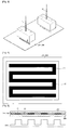
- FIG. 4 is a plane view illustrating schematically that a catalyst layer is formed according to the present invention.
- FIG. 5 is a cross-sectional view illustrating schematically that a cathode according to the present invention is formed.
- FIG. 6 is a schematic view illustrating a fuel cell according to an embodiment of the present invention.
- a first catalyst layer forming ink and a second catalyst layer forming ink further containing a hydrophobic polymer-based water-repelling enhancer in addition to the first catalyst layer forming ink are prepared (S1).
- the first catalyst layer forming ink according to the present invention may be any catalyst layer forming ink used in the art.
- the catalyst layer forming ink may include a metal catalyst or a metal catalyst on a carbon-based support; a polymer ionomer; and a solvent.
- the metal catalyst may be representatively any one selected from the group consisting of platinum, ruthenium, osmium, platinum-ruthenium alloy, platinum-osmium alloy, platinum-palladium alloy and platinum-transition metal alloy, or their mixtures, however the present invention is not limited thereto.
- the carbon-based support may be a carbon-based material, preferably any one selected from the group consisting of graphite, carbon black, acetylene black, denka black, ketjen black, activated carbon, mesoporous carbon, carbon nanotube, carbon nano fiber, carbon nano horn, carbon nano ring, carbon nano wire, fullerene (C60) and Super-P, or their mixtures.
- the polymer ionomer may be representatively a nafion ionomer or a sulfonated polymer such as sulfonated polytrifluorostyrene.
- the solvent may be any one selected from the group consisting of water, butanol, isopropanol, methanol, ethanol, n-propanol, n-butyl acetate and ethylene glycol, or their mixtures.
- the second catalyst layer forming ink according to the present invention may be prepared in the same way as the first catalyst layer forming ink, except that a hydrophobic polymer-based water-repelling enhancer is added.
- the second catalyst layer forming ink includes a metal catalyst or a metal catalyst on a carbon-based support; a polymer ionomer; a hydrophobic polymer-based water-repelling enhancer selected from the group consisting of polytetrafluoroethylene, polychlorotrifluoroethylene and fluorinated ethylene propylene copolymer; and a solvent.
- the content of the hydrophobic polymer-based water-repelling enhancer added to the second catalyst layer forming ink may be controlled as necessary through sufficient experiments.
- a weight ratio of the metal catalyst and the hydrophobic polymer-based water-repelling enhancer may be set to 1:0.02 to 0.40. If the weight ratio of hydrophobic polymer-based water-repelling enhancer to metal catalyst is 0.02 or above, the water-repelling effect is great. However, if the weight ratio exceeds 0.40, an increase rate of water-repelling effect is not good in comparison to the added amount of hydrophobic polymer-based water-repelling enhancer, and mass transfer may be deteriorated.
- the first and second catalyst layer forming inks are sprayed onto an electrolyte membrane or a gas diffusion layer by means of ink jet spraying. At this time, the first catalyst layer forming ink is sprayed to a portion facing a channel, and the second catalyst layer forming ink is sprayed to a portion not facing the channel, thereby forming a catalyst layer (S2).
- a first catalyst layer forming ink 11 and a second catalyst layer forming ink 12 are sprayed onto an electrolyte membrane 201 or a gas diffusion layer 208.
- Ink jet spraying uses the related software to adjust a spray location of inkdrops very precisely, and thus individual inkdrops of the first catalyst layer forming ink 11 and the second catalyst layer forming ink 12 may be sprayed onto preset locations of the electrolyte membrane 201 or the gas diffusion layer 208.
- FIG. 4 it is possible to spray the first catalyst layer forming ink to a portion 21 facing a channel and to spray the second catalyst layer forming ink to a portion 22 not facing the channel.
- the portion 22 of the catalyst layer, not facing the channel receives a pressure by a non-channel portion of a separator 210 contacting with a membrane electrode assembly, so pores in the gas diffusion layer 208 are reduced. If pores in the gas diffusion layer 208 are reduced, moisture is not easily discharged, so a moisture concentration of catalyst layers 203, 205 corresponding to that portion is changed differently from moisture concentrations of other regions.
- the catalyst layers 203, 205 of the present invention are configured such that the portion 22 not facing the channel has higher water-repelling property than the portion 21 facing the channel.
- the moisture concentration of the portion 22 of the catalyst layers 203, 205, not facing the channel may be kept substantially identically to the moisture concentration of the portion 21 facing the channel.
- the difference of water-repelling properties between the portion facing the channel and the portion not facing the channel may be measured in various ways. For example, this difference may be expressed using a contact angle to water.
- the difference of water-repelling properties between the portion facing the channel and the portion not facing the channel may be considered as appropriate when a difference of contact angles to water is 2° or above, preferably 5° or above, more preferably 10° or above, but the present invention is not limited thereto. If the difference of water-repelling properties is too great, reactivity in the catalyst layer may be deteriorated. Thus, the difference of water-repelling properties in the catalyst layer is considered as appropriate when the difference of contact angles is 2° to 20°.
- first and second catalyst layer forming inkdrops are sprayed to preset locations on the electrolyte membrane or the gas diffusion layer to be adjacent to each other according to the above method, a catalyst layer is formed. If the first and second catalyst layer forming inkdrops are repeatedly sprayed onto the formed catalyst layer according to the above method, it is possible to obtain a catalyst layer with a desired thickness.
- a drying process may be further executed to dry the catalyst layer.
- ink may be sprayed in a thermally treated state during the ink spraying process.
- fine inkdrops may be sprayed to desired locations by means of the ink jet spraying, so it is possible to control positions of matters included in the ink in the catalyst layer.
- the first and second catalyst layer forming inks according to the present invention can be sprayed to the portion facing a channel or the portion not facing a channel by location adjustment, so it is possible to control regions with different water-repelling properties in the catalyst layer.
- an amount of moisture in an electrode can be easily controlled by adjusting moisture concentration of the catalyst layer since the catalyst layer may have different water-repelling properties according to the channel location.
- the electrode for a fuel cell according to the present invention may be formed on an electrolyte membrane or a gas diffusion layer, so it may be used for manufacturing a membrane electrode assembly for a fuel cell according to the present invention.
- a membrane electrode assembly for a fuel cell according to the present invention includes an electrolyte membrane 201; and an anode and a cathode located at opposite sides of the electrolyte membrane 201.
- the anode and cathode may include a gas diffusion layer 208 and catalyst layers 203 and 205, respectively.
- the gas diffusion layer 208 for a fuel cell according to the present invention may include substrates 209a and 209b and microporous layers 207a and 207b formed on one side of the substrates 209a and 209b, respectively.
- the electrolyte membrane employed in the present invention may adopt any electrolyte membrane used in the art, for example any one polymer selected from the group consisting of perfluorosulfonic acid polymer, hydrocarbon-based polymer, polyimide, polyvinylidene fluoride, polyethersulfone, polyphenylene sulfide, polyphenylene oxide, polyphosphazine, polyethylene naphthalate, polyester, doped polybenzimidazol, polyether ketone, polysulfone, and their acids and bases, but the present invention is not limited thereto.
- any one polymer selected from the group consisting of perfluorosulfonic acid polymer, hydrocarbon-based polymer, polyimide, polyvinylidene fluoride, polyethersulfone, polyphenylene sulfide, polyphenylene oxide, polyphosphazine, polyethylene naphthalate, polyester, doped polybenzimidazol, polyether ketone, polysulfone, and their
- the gas diffusion layer employed in the present invention may adopt any gas diffusion layer used in the art, and typically may include a conductive substrate made of any one selected from the group consisting of carbon paper, carbon cloth and carbon felt.
- the gas diffusion layer may further include a microporous layer formed on one side of the conductive substrate, and the microporous layer may be made of a carbon-based material or a fluorine-based resin.
- the carbon-based material may be any one selected from the group consisting of graphite, carbon black, acetylene black, denka black, ketjen black, activated carbon, mesoporous carbon, carbon nanotube, carbon nano fiber, carbon nano horn, carbon nano ring, carbon nano wire, fullerene (C60) and Super-P, or their mixtures, but the present invention is not limited thereto.
- the fluorine-based resin may be any one selected from the group consisting of polytetrafluoroethylene, polyvinylidene fluoride (PVdF), polyvinyl alcohol, cellulose acetate, polyvinylidene fluoride-hexafluoropropylene copolymer (PVdF-HFP) and styrene-butadiene rubber (SBR), or their mixtures, but the present invention is not limited thereto.
- PVdF polyvinylidene fluoride
- PVdF-HFP polyvinylidene fluoride-hexafluoropropylene copolymer
- SBR styrene-butadiene rubber
- the catalyst layer is formed on the microporous layer of the gas diffusion layer.
- FIG. 6 is a schematic view illustrating a fuel cell according to an embodiment of the present invention.
- the fuel cell of the present invention includes a stack 200, a fuel providing unit 400 and an oxidant providing unit 300.
- the stack 200 includes at least one membrane electrode assembly of the present invention, and in the case that at least two membrane electrode assemblies are included, the stack 200 includes a separator interposed between the membrane electrode assemblies.
- the separator prevents the membrane electrode assemblies from being electrically connected to each other, and transfers a fuel and an oxidant provided from the external to the membrane electrode assemblies.
- the fuel providing unit 400 provides a fuel to the stack 200, and may include a fuel tank 410 for storing a fuel and a pump 420 for providing the fuel stored in the fuel tank 410 to the stack 200.
- the fuel may be gaseous or liquid hydrogen or hydrocarbon fuel, and the hydrocarbon fuel may be, for example, methanol, ethanol, propanol, butanol or natural gas.
- the oxidant providing unit 300 provides an oxidant to the stack 200.
- the oxidant is typically oxygen, and the oxidant providing unit 300 may be a pump for pumping oxygen or air.
- the cathode for a fuel cell according to the present invention may control water-repelling property of the catalyst layer differently according to locations, so it is possible to keep an amount of moisture in an electrode in a suitable way and to restrain generation of flooding, thereby improving the performance of the cell.
Landscapes
- Chemical & Material Sciences (AREA)
- Chemical Kinetics & Catalysis (AREA)
- Electrochemistry (AREA)
- General Chemical & Material Sciences (AREA)
- Engineering & Computer Science (AREA)
- Manufacturing & Machinery (AREA)
- Life Sciences & Earth Sciences (AREA)
- Sustainable Development (AREA)
- Sustainable Energy (AREA)
- Materials Engineering (AREA)
- Inert Electrodes (AREA)
- Fuel Cell (AREA)
Description
- The present invention relates to a cathode for a fuel cell having two kinds of water-repellencies, a method for preparing the same, and a membrane electrode assembly and a fuel cell having the same, and more particularly to a cathode for a fuel cell capable of controlling water-repellency of a catalyst layer, a method for preparing the same, and a membrane electrode assembly and a fuel cell having the same.
- Recently, as depletion of conventional energy resources such as oil or coal is foreseen, interest in an alternative energy is increasing. A fuel cell is one of the alternative energy, and advantageously has a high efficiency, does not emit pollutants of NOx and SOx and uses a fuel that is abundant in quantity, and therefore, the fuel cell attracts public attention.
- The fuel cell is a power generation system that converts chemical energy of a fuel and an oxidant to electrical energy, and typically hydrogen and hydrocarbon, for example methanol or butane is used as a fuel, and oxygen is used as an oxidant.
- In the fuel cell, a membrane electrode assembly (MEA) is the basic unit for generating electricity, and includes an electrolyte membrane and anode and cathode electrodes formed at opposite sides of the electrolyte membrane.
FIG. 1 illustrates the principle for generating electricity of a fuel cell, and ChemicalFigure 1 represents a reaction formula of a fuel cell in the case that hydrogen is used as a fuel. Referring toFIG. 1 and ChemicalFigure 1 , an oxidation reaction of a fuel occurs at an anode electrode to generate hydrogen ions and electrons, and the hydrogen ions move to a cathode electrode through an electrolyte membrane. The hydrogen ions transmitted through the electrolyte membrane and the electrons react with oxygen (oxidant) at the cathode electrode to generate water. This reaction causes the electrons to move to an external circuit. - Chemistry
Figure 1 - Anode electrode: H2 → 2H++ 2e-
- cathode electrode: 1/2O2+ 2H++ 2e- → H2O
- Reaction formula: H2 +1/2O2 → H2O
-
FIG. 2 illustrates a general configuration of a membrane electrode assembly for a fuel cell. Referring toFIG. 2 , a membrane electrode assembly for a fuel cell includes an electrolyte membrane, and an anode electrode and a cathode electrode located at the opposite sides of the electrolyte membrane. The anode and cathode electrodes respectively include a catalyst layer and a gas diffusion layer. The gas diffusion layer includes an electrode substrate and a microporous layer formed on the electrode substrate. - In the fuel cell, the moisture that is also a resultant material of reaction in an electrode assists ion transfer, but an excessive amount of moisture may block the micro pores in the catalyst layer or the gas diffusion layer. Namely, the moisture discharging ability in the electrode surface of a fuel cell is a factor determining performance of the cell. Thus, the moisture introduced into the electrode or the moisture generated in the electrode should be controlled suitably. If moisture is not discharged suitably, flooding occurs, which decreases the three-phase reaction sites and reduces an activation area of catalyst, thereby deteriorating the efficiency of the fuel cell.
- However, a catalyst layer of a conventional fuel cell membrane electrode assembly is made by coating with one kind of ink including a catalyst and an ionomer, so the same catalyst layer is formed entirely. Thus, it was difficult to control water repelling in the catalyst layer.
- In this regards, Japanese Laid-open Patent Publication No.
2006-286330 - Therefore, an object of the present invention is to provide a cathode for a fuel cell, which may keep moisture in an electrode to a suitable level by controlling the degree of water repelling in a catalyst layer.
- In order to accomplish the above object, the present invention provides a stack for a fuel cell according to claim 1 comprising a cathode , which includes a gas diffusion layer contacting with a separator having a channel and a catalyst layer interposed between the gas diffusion layer and an electrolyte membrane, wherein the catalyst layer of the cathode has two portions with different water-repelling properties, and a portion of the catalyst layer that does not face a channel has a higher water-repelling property than a portion that faces a channel.
- Inventors found that Japanese Laid-open Patent Publication No.
2006-286330 FIG. 5 , in the cathode for a fuel cell of the present invention, a water-repelling property is enhanced in a portion 22 of aseparator 210, which does not faces a channel, namely in a portion ofcatalyst layers gas diffusion layer 208 pressed by the separator. Thus, moisture may be more easily discharged to suitably keep moisture in a cell, thereby improving the performance of the cell. In the electrode of the present invention, the difference of water-repelling properties between the portion facing a channel and the portion not facing a channel may be considered as appropriate when a difference of contact angles to water is 2° to 20°, but the present invention is not limited thereto. - The portion of the catalyst layer in the cathode of the present invention, which faces a channel, may employ a catalyst layer generally used in the art, and it may include, for example, a metal catalyst or a metal catalyst on a carbon-based support, and a polymer ionomer.
- The portion of the catalyst layer in the cathode of the present invention, which does not face a channel and has a higher water-repelling property than the portion facing a channel, may further include a hydrophobic polymer-based water-repelling enhancer used in the art in addition to a conventional catalyst layer so as to improve the water-repelling property. For example, this portion may include a metal catalyst or a metal catalyst on a carbon-based support; a polymer ionomer, and a hydrophobic polymer-based water-repelling enhancer selected from the group consisting of polytetrafluoroethylene, polychlorotrifluoroethylene and fluorinated ethylene propylene copolymer. Here, a weight ratio of the metal catalyst to the hydrophobic polymer-based water-repelling enhancer may be set to 1:0.02 to 0.40 as necessary by those having ordinary skill in the art, but the present invention is not limited thereto.
- In another aspect of the present invention, there is also provided a method of preparing a cathode for a fuel cell, which includes (S1) preparing a first catalyst layer forming ink and a second catalyst layer forming ink that further contains a hydrophobic polymer-based water-repelling enhancer in addition to the first catalyst layer forming ink; and (S2) spraying the first and second catalyst layer forming inks to an electrolyte membrane or a gas diffusion layer by means of ink jet spraying such that the first catalyst layer forming ink is sprayed to a portion that faces a channel and the second catalyst layer forming ink is sprayed to a portion that does not face a channel.
- In this regards, Japanese Laid-open Patent Publication No.
2006-286330 - The first catalyst layer forming ink may adopt any ink generally used in the art, and for example it may include a metal catalyst or a metal catalyst on a carbon-based support; a polymer ionomer; and a solvent. The second catalyst layer forming ink may be prepared by further adding a hydrophobic polymer-based water-repelling enhancer used in the art to a conventional catalyst layer forming ink so as to improve the water-repelling property. For example, the second catalyst layer forming ink may include a metal catalyst or a metal catalyst on a carbon-based support; a polymer ionomer; a hydrophobic polymer-based water-repelling enhancer selected from the group consisting of polytetrafluoroethylene, polychlorotrifluoroethylene and fluorinated ethylene propylene copolymer; and a solvent. Also, a weight ratio of the metal catalyst to the hydrophobic polymer-based water-repelling enhancer may be set to 1:0.02 to 0.40 as necessary by those having ordinary skill in the art, but the present invention is not limited thereto.
- In this method, the ink spraying process may be executed in a thermally treated state if required.
- The above cathode may be used for a membrane electrode assembly or a fuel cell.
-
FIG. 1 is a schematic view illustrating the principle for generating electricity of a fuel cell. -
FIG. 2 is a schematic view illustrating a general configuration of a membrane electrode assembly for a fuel cell. -
FIG. 3 is a schematic view illustrating that a first catalyst layer forming ink and a second catalyst layer forming ink are respectively sprayed according to the present invention. -
FIG. 4 is a plane view illustrating schematically that a catalyst layer is formed according to the present invention. -
FIG. 5 is a cross-sectional view illustrating schematically that a cathode according to the present invention is formed. -
FIG. 6 is a schematic view illustrating a fuel cell according to an embodiment of the present invention. - Hereinafter, an electrode for a fuel cell of the present invention will be described in detail according to its preparing method. Prior to the description, it should be understood that the terms used in the specification and the appended claims should not be construed as limited to general and dictionary meanings, but interpreted based on the meanings and concepts corresponding to technical aspects of the present invention on the basis of the principle that the inventor is allowed to define terms appropriately for the best explanation.
- First, a first catalyst layer forming ink and a second catalyst layer forming ink further containing a hydrophobic polymer-based water-repelling enhancer in addition to the first catalyst layer forming ink are prepared (S1).
- The first catalyst layer forming ink according to the present invention may be any catalyst layer forming ink used in the art. For example, the catalyst layer forming ink may include a metal catalyst or a metal catalyst on a carbon-based support; a polymer ionomer; and a solvent.
- The metal catalyst may be representatively any one selected from the group consisting of platinum, ruthenium, osmium, platinum-ruthenium alloy, platinum-osmium alloy, platinum-palladium alloy and platinum-transition metal alloy, or their mixtures, however the present invention is not limited thereto.
- The carbon-based support may be a carbon-based material, preferably any one selected from the group consisting of graphite, carbon black, acetylene black, denka black, ketjen black, activated carbon, mesoporous carbon, carbon nanotube, carbon nano fiber, carbon nano horn, carbon nano ring, carbon nano wire, fullerene (C60) and Super-P, or their mixtures.
- The polymer ionomer may be representatively a nafion ionomer or a sulfonated polymer such as sulfonated polytrifluorostyrene.
- The solvent may be any one selected from the group consisting of water, butanol, isopropanol, methanol, ethanol, n-propanol, n-butyl acetate and ethylene glycol, or their mixtures.
- The second catalyst layer forming ink according to the present invention may be prepared in the same way as the first catalyst layer forming ink, except that a hydrophobic polymer-based water-repelling enhancer is added. For example, the second catalyst layer forming ink includes a metal catalyst or a metal catalyst on a carbon-based support; a polymer ionomer; a hydrophobic polymer-based water-repelling enhancer selected from the group consisting of polytetrafluoroethylene, polychlorotrifluoroethylene and fluorinated ethylene propylene copolymer; and a solvent.
- The content of the hydrophobic polymer-based water-repelling enhancer added to the second catalyst layer forming ink may be controlled as necessary through sufficient experiments. For example, a weight ratio of the metal catalyst and the hydrophobic polymer-based water-repelling enhancer may be set to 1:0.02 to 0.40. If the weight ratio of hydrophobic polymer-based water-repelling enhancer to metal catalyst is 0.02 or above, the water-repelling effect is great. However, if the weight ratio exceeds 0.40, an increase rate of water-repelling effect is not good in comparison to the added amount of hydrophobic polymer-based water-repelling enhancer, and mass transfer may be deteriorated. After the ink is prepared as mentioned above, the first and second catalyst layer forming inks are sprayed onto an electrolyte membrane or a gas diffusion layer by means of ink jet spraying. At this time, the first catalyst layer forming ink is sprayed to a portion facing a channel, and the second catalyst layer forming ink is sprayed to a portion not facing the channel, thereby forming a catalyst layer (S2).
- As shown in
FIG. 3 , a first catalystlayer forming ink 11 and a second catalystlayer forming ink 12 are sprayed onto anelectrolyte membrane 201 or agas diffusion layer 208. Ink jet spraying uses the related software to adjust a spray location of inkdrops very precisely, and thus individual inkdrops of the first catalystlayer forming ink 11 and the second catalystlayer forming ink 12 may be sprayed onto preset locations of theelectrolyte membrane 201 or thegas diffusion layer 208. Thus, as shown inFIG. 4 , it is possible to spray the first catalyst layer forming ink to aportion 21 facing a channel and to spray the second catalyst layer forming ink to a portion 22 not facing the channel. - As shown in
FIG. 5 , the portion 22 of the catalyst layer, not facing the channel, receives a pressure by a non-channel portion of aseparator 210 contacting with a membrane electrode assembly, so pores in thegas diffusion layer 208 are reduced. If pores in thegas diffusion layer 208 are reduced, moisture is not easily discharged, so a moisture concentration of catalyst layers 203, 205 corresponding to that portion is changed differently from moisture concentrations of other regions. Thus, the catalyst layers 203, 205 of the present invention are configured such that the portion 22 not facing the channel has higher water-repelling property than theportion 21 facing the channel. Thus, the moisture concentration of the portion 22 of the catalyst layers 203, 205, not facing the channel, may be kept substantially identically to the moisture concentration of theportion 21 facing the channel. - The difference of water-repelling properties between the portion facing the channel and the portion not facing the channel may be measured in various ways. For example, this difference may be expressed using a contact angle to water. In the present invention, the difference of water-repelling properties between the portion facing the channel and the portion not facing the channel may be considered as appropriate when a difference of contact angles to water is 2° or above, preferably 5° or above, more preferably 10° or above, but the present invention is not limited thereto. If the difference of water-repelling properties is too great, reactivity in the catalyst layer may be deteriorated. Thus, the difference of water-repelling properties in the catalyst layer is considered as appropriate when the difference of contact angles is 2° to 20°.
- If the first and second catalyst layer forming inkdrops are sprayed to preset locations on the electrolyte membrane or the gas diffusion layer to be adjacent to each other according to the above method, a catalyst layer is formed. If the first and second catalyst layer forming inkdrops are repeatedly sprayed onto the formed catalyst layer according to the above method, it is possible to obtain a catalyst layer with a desired thickness.
- After the ink spraying process is completed, a drying process may be further executed to dry the catalyst layer. In this case, to promote the drying process of sprayed inkdrops, ink may be sprayed in a thermally treated state during the ink spraying process.
- In the method for making a cathode for a fuel cell according to the present invention as described above, fine inkdrops may be sprayed to desired locations by means of the ink jet spraying, so it is possible to control positions of matters included in the ink in the catalyst layer. Thus, though a fuel cell have various channel patterns, the first and second catalyst layer forming inks according to the present invention can be sprayed to the portion facing a channel or the portion not facing a channel by location adjustment, so it is possible to control regions with different water-repelling properties in the catalyst layer. In addition, it would be easily expected without any experiment by those having ordinary skill in the art that an amount of moisture in an electrode can be easily controlled by adjusting moisture concentration of the catalyst layer since the catalyst layer may have different water-repelling properties according to the channel location.
- The electrode for a fuel cell according to the present invention may be formed on an electrolyte membrane or a gas diffusion layer, so it may be used for manufacturing a membrane electrode assembly for a fuel cell according to the present invention.
- As shown in
FIG. 2 , a membrane electrode assembly for a fuel cell according to the present invention includes anelectrolyte membrane 201; and an anode and a cathode located at opposite sides of theelectrolyte membrane 201. The anode and cathode may include agas diffusion layer 208 and catalyst layers 203 and 205, respectively. Thegas diffusion layer 208 for a fuel cell according to the present invention may includesubstrates microporous layers substrates - The electrolyte membrane employed in the present invention may adopt any electrolyte membrane used in the art, for example any one polymer selected from the group consisting of perfluorosulfonic acid polymer, hydrocarbon-based polymer, polyimide, polyvinylidene fluoride, polyethersulfone, polyphenylene sulfide, polyphenylene oxide, polyphosphazine, polyethylene naphthalate, polyester, doped polybenzimidazol, polyether ketone, polysulfone, and their acids and bases, but the present invention is not limited thereto.
- The gas diffusion layer employed in the present invention may adopt any gas diffusion layer used in the art, and typically may include a conductive substrate made of any one selected from the group consisting of carbon paper, carbon cloth and carbon felt. The gas diffusion layer may further include a microporous layer formed on one side of the conductive substrate, and the microporous layer may be made of a carbon-based material or a fluorine-based resin.
- The carbon-based material may be any one selected from the group consisting of graphite, carbon black, acetylene black, denka black, ketjen black, activated carbon, mesoporous carbon, carbon nanotube, carbon nano fiber, carbon nano horn, carbon nano ring, carbon nano wire, fullerene (C60) and Super-P, or their mixtures, but the present invention is not limited thereto.
- The fluorine-based resin may be any one selected from the group consisting of polytetrafluoroethylene, polyvinylidene fluoride (PVdF), polyvinyl alcohol, cellulose acetate, polyvinylidene fluoride-hexafluoropropylene copolymer (PVdF-HFP) and styrene-butadiene rubber (SBR), or their mixtures, but the present invention is not limited thereto.
- At this time, the catalyst layer is formed on the microporous layer of the gas diffusion layer.
- The present invention also provides a fuel cell including the membrane electrode assembly explained above.
FIG. 6 is a schematic view illustrating a fuel cell according to an embodiment of the present invention. Referring toFIG. 6 , the fuel cell of the present invention includes astack 200, afuel providing unit 400 and anoxidant providing unit 300. - The
stack 200 includes at least one membrane electrode assembly of the present invention, and in the case that at least two membrane electrode assemblies are included, thestack 200 includes a separator interposed between the membrane electrode assemblies. The separator prevents the membrane electrode assemblies from being electrically connected to each other, and transfers a fuel and an oxidant provided from the external to the membrane electrode assemblies. - The
fuel providing unit 400 provides a fuel to thestack 200, and may include afuel tank 410 for storing a fuel and apump 420 for providing the fuel stored in thefuel tank 410 to thestack 200. The fuel may be gaseous or liquid hydrogen or hydrocarbon fuel, and the hydrocarbon fuel may be, for example, methanol, ethanol, propanol, butanol or natural gas. - The
oxidant providing unit 300 provides an oxidant to thestack 200. The oxidant is typically oxygen, and theoxidant providing unit 300 may be a pump for pumping oxygen or air. - The cathode for a fuel cell according to the present invention may control water-repelling property of the catalyst layer differently according to locations, so it is possible to keep an amount of moisture in an electrode in a suitable way and to restrain generation of flooding, thereby improving the performance of the cell.
Claims (17)
- A stack (200) for a fuel cell, comprising:a plurality of membrane electrode assemblies, each including an electrolyte membrane (201) and an anode and a cathode respectively formed at opposite sides of the electrolyte membrane (201), each of the anode and the cathode having a catalyst layer (203, 205) and a gas diffusion layer (208) so that the catalyst layer (203, 205) contacts the electrolyte membrane (201); andseparators, each having a channel and interposed between the plurality of membrane electrode assemblies to contact the gas diffusion layer (208) of each of the anode and the cathode,wherein the portion (21) of the catalyst layer of the cathode, which faces a channel, includes a metal catalyst or a metal catalyst on a carbon-based support, and a polymer ionomer,wherein the portion (22) of the catalyst layer, which does not face a channel, in addition to the catalyst layer of portion (21) further includes a hydrophobic polymer-based water-repelling enhancer selected from the group consisting of polytetrafluoroethylene, polychlorotrifluoroethylene and fluorinated ethylene propylene copolymer,wherein the portion (22) of the catalyst layer that does not face a channel has a higher water-repelling property than a the portion (21) that faces a channel.
- The stack for a fuel cell according to claim 1,
wherein the difference of contact angles to water of the portions with different water-repelling properties is 2° to 20°. - The stack for a fuel cell according to claim 1,
wherein a weight ratio of the metal catalyst to the hydrophobic polymer-based water-repelling enhancer is 1:0.02 to 0.40. - The stack for a fuel cell according to claim 1,
wherein the metal catalyst is any one selected from the group consisting of platinum, ruthenium, osmium, platinum-ruthenium alloy, platinum-osmium alloy, platinum-palladium alloy and platinum-transition metal alloy, or their mixtures. - The stack for a fuel cell according to claim 1,
wherein the carbon-based support is any one selected from the group consisting of graphite, carbon black, acetylene black, denka black, ketjen black, activated carbon, mesoporous carbon, carbon nanotube, carbon nano fiber, carbon nano horn, carbon nano ring, carbon nano wire, fullerene (C60) and Super-P, or their mixtures. - The stack for a fuel cell according to claim 1,
wherein the polymer ionomer is nafion ionomer or sulfonated polytrifluorostyrene. - A method of preparing a cathode for a fuel cell, comprising:preparing a first catalyst layer forming ink including a metal catalyst or a metal catalyst on a carbon-based support; a polymer ionomer; and a solvent;preparing a second catalyst layer forming ink that further contains, in addition to the first catalyst layer forming ink, a hydrophobic polymer-based water-repelling enhancer selected from the group consisting of polytetrafluoroethylene, polychlorotrifluoroethylene and fluorinated ethylene propylene copolymer; andspraying the first and second catalyst layer forming inks to an electrolyte membrane or a gas diffusion layer by means of ink jet spraying such that the first catalyst layer forming ink is sprayed to a portion that faces a channel and the second catalyst layer forming ink is sprayed to a portion that does not face a channel.
- The method of preparing a cathode for a fuel cell according to claim 7,
wherein a weight ratio of the metal catalyst to the hydrophobic polymer-based water-repelling enhancer is 1:0.02 to 0.40. - The method of preparing a cathode for a fuel cell according to claim 7,
wherein the metal catalyst is any one selected from the group consisting of platinum, ruthenium, osmium, platinum-ruthenium alloy, platinum-osmium alloy, platinum-palladium alloy and platinum-transition metal alloy, or their mixtures. - The method of preparing a cathode for a fuel cell according to claim 7,
wherein the carbon-based support is any one selected from the group consisting of graphite, carbon black, acetylene black, denka black, ketjen black, activated carbon, mesoporous carbon, carbon nanotube, carbon nano fiber, carbon nano horn, carbon nano ring, carbon nano wire, fullerene (C60) and Super-P, or their mixtures. - The method of preparing a cathode for a fuel cell according to claim 7,
wherein the polymer ionomer is nafion ionomer or sulfonated polytrifluorostyrene. - The method of preparing a cathode for a fuel cell according to claim 7,
wherein the solvent is any one selected from the group consisting of water, butanol, isopropanol, methanol, ethanol, n-propanol, n-butyl acetate and ethylene glycol, or their mixtures. - The method of preparing a cathode for a fuel cell according to claim 7,
wherein the ink spraying process is executed in a thermally treated state. - The method of preparing a cathode for a fuel cell according to claim 7,
wherein, after the cathode is made, a difference of contact angles to water between the portion facing a channel and the portion not facing a channel is 2° to 20°. - The method of preparing a cathode for a fuel cell according to claim7,
wherein the electrolyte membrane is any one polymer selected from the group consisting of perfluorosulfonic acid polymer, hydrocarbon-based polymer, polyimide, polyvinylidene fluoride, polyethersulfone, polyphenylene sulfide, polyphenylene oxide, polyphosphazine, polyethylene naphthalate, polyester, doped polybenzimidazol, polyether ketone, polysulfone, and their acids and bases. - The method of preparing a cathode for a fuel cell according to claim 7,
wherein the gas diffusion layer includes a conductive substrate selected from the group consisting of carbon paper, carbon cloth and carbon felt, a carbon-based material and a fluorine-based resin. - A fuel cell, comprising:a stack (200) according to claim 1;a fuel providing unit (400) for providing a fuel to the stack; andan oxidant providing unit (300) for providing an oxidant to the stack.
Applications Claiming Priority (2)
| Application Number | Priority Date | Filing Date | Title |
|---|---|---|---|
| KR1020070104206A KR100969475B1 (en) | 2007-10-16 | 2007-10-16 | Cathode for fuel cell having two kinds of water-repellency and Method of preparing the same and Membrane electrode assembly and Fuel cell comprising the same |
| PCT/KR2008/005899 WO2009051368A2 (en) | 2007-10-16 | 2008-10-08 | Cathode for fuel cell having two kinds of water-repellency and method of preparing the same and membrane electrode assembly and fuel cell comprising the same |
Publications (3)
| Publication Number | Publication Date |
|---|---|
| EP2212953A2 EP2212953A2 (en) | 2010-08-04 |
| EP2212953A4 EP2212953A4 (en) | 2010-11-03 |
| EP2212953B1 true EP2212953B1 (en) | 2012-10-03 |
Family
ID=40567929
Family Applications (1)
| Application Number | Title | Priority Date | Filing Date |
|---|---|---|---|
| EP08839811A Active EP2212953B1 (en) | 2007-10-16 | 2008-10-08 | Cathode for fuel cell having two kinds of water-repellency and method of preparing the same and membrane electrode assembly and fuel cell comprising the same |
Country Status (7)
| Country | Link |
|---|---|
| US (2) | US8460836B2 (en) |
| EP (1) | EP2212953B1 (en) |
| JP (1) | JP5384506B2 (en) |
| KR (1) | KR100969475B1 (en) |
| CN (1) | CN101821880B (en) |
| TW (1) | TWI365564B (en) |
| WO (1) | WO2009051368A2 (en) |
Families Citing this family (12)
| Publication number | Priority date | Publication date | Assignee | Title |
|---|---|---|---|---|
| US8153435B1 (en) | 2005-03-30 | 2012-04-10 | Tracer Detection Technology Corp. | Methods and articles for identifying objects using encapsulated perfluorocarbon tracers |
| KR20130082305A (en) * | 2012-01-11 | 2013-07-19 | 삼성전자주식회사 | Hybrid silencer providing a function of separating gas-liquid in fuel cell system |
| US9782767B2 (en) * | 2013-06-14 | 2017-10-10 | Lg Chem, Ltd. | Sulfonate-based compound and polymer electrolyte membrane using same |
| JP6536477B2 (en) * | 2016-05-13 | 2019-07-03 | トヨタ自動車株式会社 | Fuel cell |
| CN109524674B (en) * | 2017-09-19 | 2022-06-21 | 粟青青 | Method for improving performance of cathode catalyst layer of membrane electrode of fuel cell |
| CN112820884A (en) * | 2019-11-18 | 2021-05-18 | 坤艾新材料科技(上海)有限公司 | Multi-organic ligand monoatomic platinum solution for preparing electrode and electrode |
| DE102019219773A1 (en) * | 2019-12-17 | 2021-06-17 | Robert Bosch Gesellschaft mit beschränkter Haftung | Gas diffusion layer for an electrochemical cell |
| CN111916765B (en) * | 2020-07-29 | 2022-02-11 | 一汽解放汽车有限公司 | Method for preparing gas diffusion layer in fuel cell |
| CN112062227A (en) * | 2020-08-10 | 2020-12-11 | 杭州洁安环保科技有限公司 | Method for reducing scaling on cathode surface |
| CN113964356A (en) * | 2021-09-28 | 2022-01-21 | 三一汽车制造有限公司 | Fuel cell membrane electrode, membrane electrode preparation method, fuel cell system and vehicle |
| CN114082574A (en) * | 2021-11-25 | 2022-02-25 | 中国科学院长春应用化学研究所 | Feeding unit for ultrasonic spraying equipment for water electrolysis and fuel cell membrane electrode preparation |
| CN116905029B (en) * | 2023-09-14 | 2023-12-01 | 北京英博新能源有限公司 | Composite catalyst, composite catalyst coating film, preparation method of composite catalyst coating film and water electrolysis hydrogen production equipment |
Family Cites Families (27)
| Publication number | Priority date | Publication date | Assignee | Title |
|---|---|---|---|---|
| US7098163B2 (en) * | 1998-08-27 | 2006-08-29 | Cabot Corporation | Method of producing membrane electrode assemblies for use in proton exchange membrane and direct methanol fuel cells |
| JP4233208B2 (en) * | 2000-08-11 | 2009-03-04 | 三洋電機株式会社 | Fuel cell |
| JP3843838B2 (en) | 2001-12-28 | 2006-11-08 | 日産自動車株式会社 | Fuel cell |
| US20040229108A1 (en) * | 2002-11-08 | 2004-11-18 | Valdez Thomas I. | Anode structure for direct methanol fuel cell |
| JP2004327358A (en) * | 2003-04-28 | 2004-11-18 | Nissan Motor Co Ltd | Polymer electrolyte fuel cell |
| DE10344500A1 (en) * | 2003-09-24 | 2005-05-19 | Basell Polyolefine Gmbh | Loop reactor olefinic polymerization of e.g. ethylene includes reactor tube having diameter that varies based on predetermined reactor tube diameter and has widening and narrowing in a region other than that of axial pump |
| US7846591B2 (en) * | 2004-02-17 | 2010-12-07 | Gm Global Technology Operations, Inc. | Water management layer on flowfield in PEM fuel cell |
| JP4592317B2 (en) * | 2004-03-31 | 2010-12-01 | 大日本印刷株式会社 | Catalyst layer transfer sheet and solid electrolyte membrane with catalyst layer |
| JP2006012476A (en) * | 2004-06-23 | 2006-01-12 | Nissan Motor Co Ltd | Membrane-electrode assembly for fuel cell |
| KR100567408B1 (en) * | 2004-07-20 | 2006-04-07 | 주식회사 프로파워 | Membrane-electrode assembly having a dual structure catalyst layer and a method of manufacturing the same |
| JP2006040767A (en) * | 2004-07-28 | 2006-02-09 | Nissan Motor Co Ltd | Solid polymer fuel electrode |
| US9346674B2 (en) | 2004-10-28 | 2016-05-24 | Samsung Sdi Co., Ltd. | Catalyst for a fuel cell, a method of preparing the same, and a fuel cell system comprising the same |
| KR100599814B1 (en) | 2004-10-28 | 2006-07-12 | 삼성에스디아이 주식회사 | Catalyst for fuel cell, method of preparation same, and fuel cell system comprising same |
| US7927760B2 (en) * | 2004-12-17 | 2011-04-19 | The Penn State Research Foundation | Methods to control water flow and distribution in direct methanol fuel cells |
| US8029943B2 (en) * | 2005-02-28 | 2011-10-04 | GM Global Technology Operations LLC | Method to make conductive hydrophilic fuel cell elements |
| JP2006286330A (en) | 2005-03-31 | 2006-10-19 | Equos Research Co Ltd | Fuel cell and catalyst layer therefor |
| US8377607B2 (en) * | 2005-06-30 | 2013-02-19 | GM Global Technology Operations LLC | Fuel cell contact element including a TiO2 layer and a conductive layer |
| JP2007123235A (en) * | 2005-07-05 | 2007-05-17 | Toyota Motor Corp | Membrane-electrode assembly for fuel cell |
| JP2007048753A (en) * | 2005-08-11 | 2007-02-22 | Gm Global Technology Operations Inc | FUEL CELL HAVING CONTACT ELEMENT INCLUDING TiO2 LAYER AND CONDUCTIVE LAYER |
| JP2007172909A (en) * | 2005-12-20 | 2007-07-05 | Matsushita Electric Ind Co Ltd | Direct type fuel cell and direct type fuel cell system |
| CN100472872C (en) * | 2006-02-01 | 2009-03-25 | 松下电器产业株式会社 | Direct oxidation fuel cell and method for operating direct oxidation fuel cell system |
| US7413826B2 (en) * | 2006-02-16 | 2008-08-19 | Matsushita Electric Industrial Co., Ltd. | Anode electrodes for direct oxidation fuel cells and systems operating with concentrated liquid fuel |
| KR20070098136A (en) * | 2006-03-31 | 2007-10-05 | 삼성에스디아이 주식회사 | Membrane-electrode assembly for fuel cell and fuel cell system comprising same |
| JP5151205B2 (en) * | 2007-03-27 | 2013-02-27 | トヨタ自動車株式会社 | Electrode catalyst layer for fuel cell and method for producing the same |
| US7732081B2 (en) * | 2007-05-23 | 2010-06-08 | Gm Global Technology Operations, Inc. | Hydrophilic/hydrophobic patterned surfaces and methods of making and using the same |
| JP5188872B2 (en) * | 2008-05-09 | 2013-04-24 | パナソニック株式会社 | Direct oxidation fuel cell |
| US7901832B2 (en) * | 2008-05-13 | 2011-03-08 | GM Global Technology Operations LLC | Bipolar plate with inlet and outlet water management features |
-
2007
- 2007-10-16 KR KR1020070104206A patent/KR100969475B1/en active IP Right Grant
-
2008
- 2008-10-08 WO PCT/KR2008/005899 patent/WO2009051368A2/en active Application Filing
- 2008-10-08 US US12/682,868 patent/US8460836B2/en active Active
- 2008-10-08 JP JP2010529851A patent/JP5384506B2/en active Active
- 2008-10-08 EP EP08839811A patent/EP2212953B1/en active Active
- 2008-10-08 CN CN200880111457.2A patent/CN101821880B/en active Active
- 2008-10-16 TW TW097139738A patent/TWI365564B/en active
-
2013
- 2013-05-09 US US13/890,832 patent/US9059470B2/en active Active
Also Published As
| Publication number | Publication date |
|---|---|
| US8460836B2 (en) | 2013-06-11 |
| JP5384506B2 (en) | 2014-01-08 |
| TWI365564B (en) | 2012-06-01 |
| EP2212953A2 (en) | 2010-08-04 |
| KR100969475B1 (en) | 2010-07-14 |
| TW200926487A (en) | 2009-06-16 |
| WO2009051368A3 (en) | 2009-07-16 |
| US9059470B2 (en) | 2015-06-16 |
| US20130316075A1 (en) | 2013-11-28 |
| KR20090038748A (en) | 2009-04-21 |
| CN101821880A (en) | 2010-09-01 |
| WO2009051368A2 (en) | 2009-04-23 |
| US20100297519A1 (en) | 2010-11-25 |
| EP2212953A4 (en) | 2010-11-03 |
| JP2011501357A (en) | 2011-01-06 |
| CN101821880B (en) | 2014-04-30 |
Similar Documents
| Publication | Publication Date | Title |
|---|---|---|
| EP2212953B1 (en) | Cathode for fuel cell having two kinds of water-repellency and method of preparing the same and membrane electrode assembly and fuel cell comprising the same | |
| EP2212952B1 (en) | Electrode for fuel cell and method of preparing the same and membrane electrode assembly and fuel cell comprising the same | |
| US9780396B2 (en) | Method of operating fuel cell with high power and high power fuel cell system | |
| KR101728206B1 (en) | Separator for fuel cell and fuel cell comprising the same | |
| EP2235771B1 (en) | Electrode for fuel cell having two kinds of hydrophilicity and method for preparing the same and membrane electrode assembly and fuel cell comprising the same | |
| KR100961836B1 (en) | Electrode for fuel cell comprising catalyst line and ionomer line and Method of preparing the same and Membrane electrode assembly and Fuel cell comprising the same | |
| KR100999289B1 (en) | An electrode for proton exchange membrane fuel cell comprising double catalyst layer and method for preparation of the same | |
| KR101229597B1 (en) | Membrane electrode assembly for fuel cell and Method of preparing the same and Fuel cell comprising the same | |
| KR101153027B1 (en) | Electrode for fuel cell comprising ink lines with different directions, Method of preparing the same, Membrane electrode assembly and Fuel cell comprising the same | |
| KR101098676B1 (en) | Method of preparing the electrode for fuel cell and Membrane electrode assembly and Fuel cell comprising the electrode made by the same | |
| KR101573147B1 (en) | Electrode for fuel cell, membrane electrode assembly comprising the same and fuel cell comprising the same | |
| KR101006006B1 (en) | Electrode for fuel cell and Method of preparing the same and Membrane electrode assembly and Fuel cell comprising the same | |
| KR101132459B1 (en) | Method of preparing an electrode for fuel cell and Electrode prepared by the method and Membrane electrode assembly and Fuel cell comprising the same |
Legal Events
| Date | Code | Title | Description |
|---|---|---|---|
| PUAI | Public reference made under article 153(3) epc to a published international application that has entered the european phase |
Free format text: ORIGINAL CODE: 0009012 |
|
| 17P | Request for examination filed |
Effective date: 20100507 |
|
| AK | Designated contracting states |
Kind code of ref document: A2 Designated state(s): AT BE BG CH CY CZ DE DK EE ES FI FR GB GR HR HU IE IS IT LI LT LU LV MC MT NL NO PL PT RO SE SI SK TR |
|
| AX | Request for extension of the european patent |
Extension state: AL BA MK RS |
|
| RIN1 | Information on inventor provided before grant (corrected) |
Inventor name: JEONG, SEONG-UK Inventor name: LEE, SANG-HYUN Inventor name: LEE, CHANG-SONG Inventor name: LEE, WON-HO Inventor name: KIM, HYUK |
|
| RIN1 | Information on inventor provided before grant (corrected) |
Inventor name: KIM, HYUK Inventor name: JEONG, SEONG-UK Inventor name: LEE, CHANG-SONG Inventor name: LEE, WON-HO Inventor name: LEE, SANG-HYUN |
|
| A4 | Supplementary search report drawn up and despatched |
Effective date: 20101001 |
|
| RIC1 | Information provided on ipc code assigned before grant |
Ipc: H01M 8/04 20060101ALI20100924BHEP Ipc: H01M 4/86 20060101AFI20090513BHEP |
|
| REG | Reference to a national code |
Ref country code: DE Ref legal event code: R079 Ref document number: 602008019196 Country of ref document: DE Free format text: PREVIOUS MAIN CLASS: H01M0004860000 Ipc: H01M0008040000 |
|
| RIC1 | Information provided on ipc code assigned before grant |
Ipc: H01M 8/10 20060101ALI20111027BHEP Ipc: H01M 4/86 20060101ALI20111027BHEP Ipc: H01M 8/04 20060101AFI20111027BHEP |
|
| GRAP | Despatch of communication of intention to grant a patent |
Free format text: ORIGINAL CODE: EPIDOSNIGR1 |
|
| DAX | Request for extension of the european patent (deleted) | ||
| GRAS | Grant fee paid |
Free format text: ORIGINAL CODE: EPIDOSNIGR3 |
|
| GRAA | (expected) grant |
Free format text: ORIGINAL CODE: 0009210 |
|
| AK | Designated contracting states |
Kind code of ref document: B1 Designated state(s): AT BE BG CH CY CZ DE DK EE ES FI FR GB GR HR HU IE IS IT LI LT LU LV MC MT NL NO PL PT RO SE SI SK TR |
|
| REG | Reference to a national code |
Ref country code: GB Ref legal event code: FG4D |
|
| REG | Reference to a national code |
Ref country code: AT Ref legal event code: REF Ref document number: 578352 Country of ref document: AT Kind code of ref document: T Effective date: 20121015 Ref country code: CH Ref legal event code: EP |
|
| REG | Reference to a national code |
Ref country code: IE Ref legal event code: FG4D |
|
| REG | Reference to a national code |
Ref country code: DE Ref legal event code: R096 Ref document number: 602008019196 Country of ref document: DE Effective date: 20121129 |
|
| REG | Reference to a national code |
Ref country code: AT Ref legal event code: MK05 Ref document number: 578352 Country of ref document: AT Kind code of ref document: T Effective date: 20121003 |
|
| PG25 | Lapsed in a contracting state [announced via postgrant information from national office to epo] |
Ref country code: SI Free format text: LAPSE BECAUSE OF FAILURE TO SUBMIT A TRANSLATION OF THE DESCRIPTION OR TO PAY THE FEE WITHIN THE PRESCRIBED TIME-LIMIT Effective date: 20121003 |
|
| REG | Reference to a national code |
Ref country code: NL Ref legal event code: VDEP Effective date: 20121003 |
|
| REG | Reference to a national code |
Ref country code: LT Ref legal event code: MG4D |
|
| PG25 | Lapsed in a contracting state [announced via postgrant information from national office to epo] |
Ref country code: ES Free format text: LAPSE BECAUSE OF FAILURE TO SUBMIT A TRANSLATION OF THE DESCRIPTION OR TO PAY THE FEE WITHIN THE PRESCRIBED TIME-LIMIT Effective date: 20130114 Ref country code: FI Free format text: LAPSE BECAUSE OF FAILURE TO SUBMIT A TRANSLATION OF THE DESCRIPTION OR TO PAY THE FEE WITHIN THE PRESCRIBED TIME-LIMIT Effective date: 20121003 Ref country code: NO Free format text: LAPSE BECAUSE OF FAILURE TO SUBMIT A TRANSLATION OF THE DESCRIPTION OR TO PAY THE FEE WITHIN THE PRESCRIBED TIME-LIMIT Effective date: 20130103 Ref country code: IS Free format text: LAPSE BECAUSE OF FAILURE TO SUBMIT A TRANSLATION OF THE DESCRIPTION OR TO PAY THE FEE WITHIN THE PRESCRIBED TIME-LIMIT Effective date: 20130203 Ref country code: SE Free format text: LAPSE BECAUSE OF FAILURE TO SUBMIT A TRANSLATION OF THE DESCRIPTION OR TO PAY THE FEE WITHIN THE PRESCRIBED TIME-LIMIT Effective date: 20121003 Ref country code: HR Free format text: LAPSE BECAUSE OF FAILURE TO SUBMIT A TRANSLATION OF THE DESCRIPTION OR TO PAY THE FEE WITHIN THE PRESCRIBED TIME-LIMIT Effective date: 20121003 Ref country code: NL Free format text: LAPSE BECAUSE OF FAILURE TO SUBMIT A TRANSLATION OF THE DESCRIPTION OR TO PAY THE FEE WITHIN THE PRESCRIBED TIME-LIMIT Effective date: 20121003 Ref country code: LT Free format text: LAPSE BECAUSE OF FAILURE TO SUBMIT A TRANSLATION OF THE DESCRIPTION OR TO PAY THE FEE WITHIN THE PRESCRIBED TIME-LIMIT Effective date: 20121003 |
|
| PG25 | Lapsed in a contracting state [announced via postgrant information from national office to epo] |
Ref country code: LV Free format text: LAPSE BECAUSE OF FAILURE TO SUBMIT A TRANSLATION OF THE DESCRIPTION OR TO PAY THE FEE WITHIN THE PRESCRIBED TIME-LIMIT Effective date: 20121003 Ref country code: PL Free format text: LAPSE BECAUSE OF FAILURE TO SUBMIT A TRANSLATION OF THE DESCRIPTION OR TO PAY THE FEE WITHIN THE PRESCRIBED TIME-LIMIT Effective date: 20121003 Ref country code: BE Free format text: LAPSE BECAUSE OF FAILURE TO SUBMIT A TRANSLATION OF THE DESCRIPTION OR TO PAY THE FEE WITHIN THE PRESCRIBED TIME-LIMIT Effective date: 20121003 Ref country code: MC Free format text: LAPSE BECAUSE OF NON-PAYMENT OF DUE FEES Effective date: 20121031 Ref country code: PT Free format text: LAPSE BECAUSE OF FAILURE TO SUBMIT A TRANSLATION OF THE DESCRIPTION OR TO PAY THE FEE WITHIN THE PRESCRIBED TIME-LIMIT Effective date: 20130204 Ref country code: GR Free format text: LAPSE BECAUSE OF FAILURE TO SUBMIT A TRANSLATION OF THE DESCRIPTION OR TO PAY THE FEE WITHIN THE PRESCRIBED TIME-LIMIT Effective date: 20130104 |
|
| REG | Reference to a national code |
Ref country code: CH Ref legal event code: PL |
|
| PG25 | Lapsed in a contracting state [announced via postgrant information from national office to epo] |
Ref country code: AT Free format text: LAPSE BECAUSE OF FAILURE TO SUBMIT A TRANSLATION OF THE DESCRIPTION OR TO PAY THE FEE WITHIN THE PRESCRIBED TIME-LIMIT Effective date: 20121003 |
|
| REG | Reference to a national code |
Ref country code: IE Ref legal event code: MM4A |
|
| PG25 | Lapsed in a contracting state [announced via postgrant information from national office to epo] |
Ref country code: CH Free format text: LAPSE BECAUSE OF NON-PAYMENT OF DUE FEES Effective date: 20121031 Ref country code: CZ Free format text: LAPSE BECAUSE OF FAILURE TO SUBMIT A TRANSLATION OF THE DESCRIPTION OR TO PAY THE FEE WITHIN THE PRESCRIBED TIME-LIMIT Effective date: 20121003 Ref country code: IE Free format text: LAPSE BECAUSE OF NON-PAYMENT OF DUE FEES Effective date: 20121008 Ref country code: EE Free format text: LAPSE BECAUSE OF FAILURE TO SUBMIT A TRANSLATION OF THE DESCRIPTION OR TO PAY THE FEE WITHIN THE PRESCRIBED TIME-LIMIT Effective date: 20121003 Ref country code: SK Free format text: LAPSE BECAUSE OF FAILURE TO SUBMIT A TRANSLATION OF THE DESCRIPTION OR TO PAY THE FEE WITHIN THE PRESCRIBED TIME-LIMIT Effective date: 20121003 Ref country code: BG Free format text: LAPSE BECAUSE OF FAILURE TO SUBMIT A TRANSLATION OF THE DESCRIPTION OR TO PAY THE FEE WITHIN THE PRESCRIBED TIME-LIMIT Effective date: 20130103 Ref country code: DK Free format text: LAPSE BECAUSE OF FAILURE TO SUBMIT A TRANSLATION OF THE DESCRIPTION OR TO PAY THE FEE WITHIN THE PRESCRIBED TIME-LIMIT Effective date: 20121003 Ref country code: LI Free format text: LAPSE BECAUSE OF NON-PAYMENT OF DUE FEES Effective date: 20121031 |
|
| PLBE | No opposition filed within time limit |
Free format text: ORIGINAL CODE: 0009261 |
|
| STAA | Information on the status of an ep patent application or granted ep patent |
Free format text: STATUS: NO OPPOSITION FILED WITHIN TIME LIMIT |
|
| PG25 | Lapsed in a contracting state [announced via postgrant information from national office to epo] |
Ref country code: IT Free format text: LAPSE BECAUSE OF FAILURE TO SUBMIT A TRANSLATION OF THE DESCRIPTION OR TO PAY THE FEE WITHIN THE PRESCRIBED TIME-LIMIT Effective date: 20121003 Ref country code: RO Free format text: LAPSE BECAUSE OF FAILURE TO SUBMIT A TRANSLATION OF THE DESCRIPTION OR TO PAY THE FEE WITHIN THE PRESCRIBED TIME-LIMIT Effective date: 20121003 |
|
| REG | Reference to a national code |
Ref country code: FR Ref legal event code: ST Effective date: 20130805 |
|
| 26N | No opposition filed |
Effective date: 20130704 |
|
| REG | Reference to a national code |
Ref country code: DE Ref legal event code: R097 Ref document number: 602008019196 Country of ref document: DE Effective date: 20130704 |
|
| PG25 | Lapsed in a contracting state [announced via postgrant information from national office to epo] |
Ref country code: CY Free format text: LAPSE BECAUSE OF FAILURE TO SUBMIT A TRANSLATION OF THE DESCRIPTION OR TO PAY THE FEE WITHIN THE PRESCRIBED TIME-LIMIT Effective date: 20121003 Ref country code: FR Free format text: LAPSE BECAUSE OF NON-PAYMENT OF DUE FEES Effective date: 20121203 Ref country code: MT Free format text: LAPSE BECAUSE OF FAILURE TO SUBMIT A TRANSLATION OF THE DESCRIPTION OR TO PAY THE FEE WITHIN THE PRESCRIBED TIME-LIMIT Effective date: 20121003 |
|
| PG25 | Lapsed in a contracting state [announced via postgrant information from national office to epo] |
Ref country code: TR Free format text: LAPSE BECAUSE OF FAILURE TO SUBMIT A TRANSLATION OF THE DESCRIPTION OR TO PAY THE FEE WITHIN THE PRESCRIBED TIME-LIMIT Effective date: 20121003 |
|
| PG25 | Lapsed in a contracting state [announced via postgrant information from national office to epo] |
Ref country code: LU Free format text: LAPSE BECAUSE OF NON-PAYMENT OF DUE FEES Effective date: 20121008 |
|
| PG25 | Lapsed in a contracting state [announced via postgrant information from national office to epo] |
Ref country code: HU Free format text: LAPSE BECAUSE OF FAILURE TO SUBMIT A TRANSLATION OF THE DESCRIPTION OR TO PAY THE FEE WITHIN THE PRESCRIBED TIME-LIMIT Effective date: 20081008 |
|
| PGFP | Annual fee paid to national office [announced via postgrant information from national office to epo] |
Ref country code: GB Payment date: 20230920 Year of fee payment: 16 |
|
| PGFP | Annual fee paid to national office [announced via postgrant information from national office to epo] |
Ref country code: DE Payment date: 20230920 Year of fee payment: 16 |