EP2212513B1 - Pipe handling apparatus and method - Google Patents
Pipe handling apparatus and method Download PDFInfo
- Publication number
- EP2212513B1 EP2212513B1 EP08842699.4A EP08842699A EP2212513B1 EP 2212513 B1 EP2212513 B1 EP 2212513B1 EP 08842699 A EP08842699 A EP 08842699A EP 2212513 B1 EP2212513 B1 EP 2212513B1
- Authority
- EP
- European Patent Office
- Prior art keywords
- pipe
- boom
- arm
- handling apparatus
- skid
- Prior art date
- Legal status (The legal status is an assumption and is not a legal conclusion. Google has not performed a legal analysis and makes no representation as to the accuracy of the status listed.)
- Not-in-force
Links
Images


Classifications
-
- E—FIXED CONSTRUCTIONS
- E21—EARTH OR ROCK DRILLING; MINING
- E21B—EARTH OR ROCK DRILLING; OBTAINING OIL, GAS, WATER, SOLUBLE OR MELTABLE MATERIALS OR A SLURRY OF MINERALS FROM WELLS
- E21B19/00—Handling rods, casings, tubes or the like outside the borehole, e.g. in the derrick; Apparatus for feeding the rods or cables
- E21B19/08—Apparatus for feeding the rods or cables; Apparatus for increasing or decreasing the pressure on the drilling tool; Apparatus for counterbalancing the weight of the rods
- E21B19/087—Apparatus for feeding the rods or cables; Apparatus for increasing or decreasing the pressure on the drilling tool; Apparatus for counterbalancing the weight of the rods by means of a swinging arm
-
- E—FIXED CONSTRUCTIONS
- E21—EARTH OR ROCK DRILLING; MINING
- E21B—EARTH OR ROCK DRILLING; OBTAINING OIL, GAS, WATER, SOLUBLE OR MELTABLE MATERIALS OR A SLURRY OF MINERALS FROM WELLS
- E21B19/00—Handling rods, casings, tubes or the like outside the borehole, e.g. in the derrick; Apparatus for feeding the rods or cables
- E21B19/14—Racks, ramps, troughs or bins, for holding the lengths of rod singly or connected; Handling between storage place and borehole
-
- E—FIXED CONSTRUCTIONS
- E21—EARTH OR ROCK DRILLING; MINING
- E21B—EARTH OR ROCK DRILLING; OBTAINING OIL, GAS, WATER, SOLUBLE OR MELTABLE MATERIALS OR A SLURRY OF MINERALS FROM WELLS
- E21B19/00—Handling rods, casings, tubes or the like outside the borehole, e.g. in the derrick; Apparatus for feeding the rods or cables
- E21B19/14—Racks, ramps, troughs or bins, for holding the lengths of rod singly or connected; Handling between storage place and borehole
- E21B19/15—Racking of rods in horizontal position; Handling between horizontal and vertical position
- E21B19/155—Handling between horizontal and vertical position
Definitions
- the present invention relates to a tubular or pipe handling apparatus. More particularly, the present invention relates to a pipe handling apparatus for moving a pipe from a horizontal orientation to a vertical orientation. Additionally, the present invention relates to pipe handling apparatus for installing pipes upon a drilling rig. The present invention also relates to pipe handling apparatus that moves the pipe with a single degree of freedom.
- Drill rigs have utilized several methods for transferring tubular members from a pipe rack adjacent to the drill floor to a mousehole in the drill floor or the well bore for connection to a previously transferred tubular or tubular string.
- tubular or "pipe” as used herein includes all forms of drill pipe, drill collars, casing, liner, bottom hole assemblies (BHA), and other types of tubulars known in the art.
- drill rigs have utilized a combination of the rig cranes and the traveling system for transferring a tubular from the pipe rack to a vertical position above the center of the well.
- the obvious disadvantage with the prior art systems is that there is a significant manual involvement in attaching the pipe elevators to the tubular and moving the pipe from the drill rack to the rotary table. This manual transfer operation in the vicinity of workers is potentially dangerous and has caused numerous injuries in drilling operations.
- the hoisting system may allow the tubular to come into contact with the catwalk or other portions of the rig as the tubular is transferred from the pipe rack to the drill floor. This can damage the tubular and may affect the integrity of the connections between successive tubulars in the well.
- One method of transferring pipe from the rack to the well platform comprises tying one end of a line on the rig around a selected pipe on the pipe rack.
- the pipe is thereafter lifted up onto the platform and the lower end thereof is placed into the mousehole.
- the mousehole is simply an upright, elongate cylindrical container adjacent the rotary table which supports the pipe temporally.
- slips are secured about the drill string on the rotary table thereby supporting the same in the well bore.
- the pipe is disconnected from the traveling equipment and the elevators, or the kelly, are connected to the pipe in the mousehole.
- the traveling block is raised thereby positioning the pipe over the drill string and tongs are used to secure the pipe to the upper end of the drill string.
- the drill pipe elevators suspend the drill pipe from a collar which is formed around one end of the pipe and do not clamp the pipe thereby permitting rotational pipe movement in order to threadably engage the same to the drill string.
- a prior art technique for moving joints of casing from racks adjacent to the drilling rig comprises tying a line from the rig onto one end of a selected casing joint on the rack.
- the line is raised by lifting the casing joint up a ramp leading to the rig platform.
- the rope lifts the casing from the rack, the lower end of the casing swings across the platform in a dangerous manner. The danger increases when a floating system is used in connection with drilling. Since the rope is tied around the casing at one end thereof, the casing does not hang vertically, but rather tilts somewhat.
- a man working on a platform elevated above the rig floor must hold the top of the casing and straighten it out while the casing is threaded into the casing string which is suspended in the well bore by slips positioned on the rotary table.
- U.S. Patent No. 3,177,944 issued on April 13, 1965 to R.N. Knight , describes a racking mechanism for earth boring equipment that provides for horizontal storage of pipe lengths on one side of and clear of the derrick. This is achieved by means of a transport arm which is pivoted toward the base of the derrick for swing movement in a vertical plane. The outer end of the arm works between a substantially vertical position in which it can accept a pipe length from, or deliver a pipe length to, a station in the derrick, and a substantially horizontal portion in which the arm can deliver a pipe length to, or accept a pipe length from, a station associated with storage means on one side of the derrick.
- U.S. Patent No. 3,464,507, issued on September 2, 1969 to E.L. Alexander et al. teaches a portable rotary pipe handling system.
- This system includes a mast pivotally mounted and movable between a reclining transport position to a desired position at the site drilling operations which may be at any angle up to vertical.
- the mast has guides for a traveling mechanism that includes a block movable up and down the mast through operation of cables reeved from the traveling block over crown block pulleys into a drawwork.
- a power drill drive is carried by the traveling block.
- An elevator for drill pipe is carried by arm swingably mounted relative to the power unit.
- Power tongs, slips, and slip bushings are supported adjacent the lower end of the mast and adapted to have a drill pipe extend therethrough from a drive bushing connected to a power drive whereby the drill pipe is extended in the direction of the hole to be drilled.
- U.S. Patent No. 3,633,771 issued on January 11, 1972 to Woolslayer et al. discloses an apparatus for moving drill pipe into and out of an oil well derrick.
- a stand of pipe is gripped by a strongback which is pivotally mounted to one end of a boom.
- the boom swings the strongback over the rotary table thereby vertically aligning the pipe stand with the drill string.
- all vertical movement of the pipe is accomplished by the elevator suspended from the traveling block.
- U.S. Patent No. 3,860,122 issued on January 14, 1975 to L.C. Cernosek , describes an apparatus for transferring a tubular member, such as a pipe, from a storage area to an oil well drilling platform.
- the positioning apparatus includes a pipe positioner mounted on a platform for moving the pipe to a release position whereby the pipe can be released to be lowered to a submerged position.
- a load means is operably attached or associated with the platform and positioning means in order to move the pipe in a stored position to a transfer position in which the pipe is transferred to the positioner.
- the positioner includes a tower having pivotally mounted thereon a pipe track with a plurality of pipe clamp assemblies which are adapted to receive a pipe length.
- the pipe track is pivotally movable by hydraulic power means or gear means between a transfer position in which pipe is moved into the plurality of clamp assemblies and the release position in which the pipe is released for movement to a submerged position.
- U.S. Patent No. 3,986,619 shows a pipe handling apparatus for an oil well drilling derrick.
- the inner end of the boom is pivotally supported on a horizontal axis in front of a well.
- a clamping means is pivotally connected to the outer end of the boom on an axis parallel to the horizontal axis at one end.
- the clamping means allows the free end of the drill pipe to swing across the boom as the outer end of the boom is raised or lowered.
- a line is connected at one end with the traveling block that raises and lowers the elevators and at the other end to the boom so as to pass around sheaves.
- U.S. Patent No. 4,172,684 issued on October 30, 1979 to C. Jenkins shows a floor level pipe handling apparatus which is mounted on the floor of an oil well derrick suitable structure.
- This apparatus includes a support that is rockable on an axis perpendicular to the centerline of a well being drilled.
- One end of an arm is pivotally mounted on the support on an axis transverse to the centerline of the well.
- the opposite end of the arm carries a pair of shoes having laterally opening pipe-receiving seats facing away from the arm.
- the free end of the arm can be swung toward and away from the well centerline and the arm support can be rocked to swing the arm laterally.
- U.S. Patent No. 4,403,666 issued on September 13, 1983 to C.A. Willis shows self-centering tongs and a transfer arm for a drilling apparatus.
- the clamps of the transfer arm are resiliently mounted to the transfer arm so as to provide limited axial movement of the clamps and thereby of a clamped down hole tubular.
- a pair of automatic, self-centering, hydraulic tongs are provided for making up and breaking out threaded connections of tubulars.
- U.S. Patent No. 4,407,629 issued on October 4, 1983 to C.A. Willis , teaches a lifting apparatus for downhole tubulars.
- This lifting apparatus includes two rotatably mounted clamps which are rotatable between a side loading-position so as to facilitate the loading and unloading in the horizontal position, and a central position, in which a clamped tubular is aligned with the drilling axis when the boom is in the vertical position.
- An automatic hydraulic sequencing circuit is provided to automatically rotate the clamps into the side-loading position whenever the boom is pivoted with a down-hole tubular positioned in the clamp. In this position, the clamped tubular is aligned with a safety plate mounted on the boom to prevent a clamped tubular from slipping from the clamps.
- U.S. Patent No. 4,492,501 provides a platform positioning system for a drilling operation which includes a support structure and a transfer arm pivotally connected to the support structure to rotate about a first axis.
- This platform positioning system includes a platform which is pivotally connected to the support structure to rotate about a second axis, and rod which is mounted between the transfer arm and the platform.
- the position of the arm and platform axes and the length of the rod are selected such that the transfer arm automatically and progressively raises the platform to the raised position by means of the rod as the transfer arm moves to the raised position.
- the transfer arm automatically and progressively lowers the platform to the lowered position by means of the rod as the transfer arm moves to the lowered position.
- U.S. Patent No. 4,595,066 issued on June 17, 1986 to Nelmark et al. , provides an apparatus for handling drill pipes and used in association with blast holes. This system allows a drill pipe to be more easily connected and disconnected to a drill string in a hole being drilled at an angle.
- a receptacle is formed at the lower end of the carrier that has hydraulically operated doors secured by a hydraulically operated lock.
- a gate near the upper end is pneumatically operated in response to the hydraulic operation of the receptacle lock.
- U.S. Patent No. 4,822,230 issued on April 18, 1989 to P. Slettedal teaches a pipe handling apparatus which is adapted for automated drilling operations. Drill pipes are manipulated between substantially horizontal and vertical positions.
- the apparatus is used with a top mounted drilling device which is rotatable about a substantially horizontal axis.
- the apparatus utilizes a strongback provided with clamps to hold and manipulate pipes.
- the strongback is rotatably connected to the same axis as the drilling device.
- the strongback moves up or down with the drilling device.
- a brace unit is attached to the strongback to be rotatable about a second axis.
- U.S. Patent No. 4,834,604 issued on May 30, 1989 to Brittain et al. , provides a pipe moving apparatus and method for moving casing or pipe from a horizontal position adjacent a well to a vertical position over the well bore.
- the machine includes a boom movable between a lowered position and a raised position by a hydraulic ram.
- a strongback grips the pipe and holds the same until the pipe is vertically positioned. Thereafter, a hydraulic ram on the strongback is actuated thereby lowering the pipe or casing onto the string suspended in the well bore and the additional pipe or casing joint is threaded thereto.
- U.S. Patent No. 4,708,581 issued on November 24, 1987 H.L. Adair provides a method for positioning a transfer arm for the movement of drill pipe.
- a drilling mast and a transfer arm is mounted at a first axis adjacent the mast to move between a lowered position near ground level and an upper position aligned with the mast.
- a reaction point anchor is fixed with respect to the drilling mast and spaced from the first axis.
- a fixed length link is pivotably mounted to the transfer arm at a second axis, spaced from the first axis, and a first single stage cylinder is pivotably mounted at one end to the distal end of the link and at the other end to the transfer arm.
- a second single stage hydraulic cylinder is pivotably mounted at one end to the distal end of the link and at the other end to the reaction point.
- U.S. Patent No. 4,759,414 issued on July 26,1988 to C.A. Willis provides a drilling machine which includes a drilling superstructure skid which defines two spaced-apart parallel skid runners and a platform.
- the platform supports a drawworks mounted on a drawworks skid and a pipe boom is mounted on a pipe boom skid sized to fit between the skid runners of the drilling substructure skid.
- the drilling substructure skid supports four legs which, in turn, support a drilling platform on which is mounted a lower mast section.
- the pipe boom skid mounts a pipe boom as well as a boom linkage, a motor, and a hydraulic pump adapted to power the pipe boom linkage. Mechanical position locks hold the upper skid in relative position over the lower skid.
- U.S. Patent No. 5,458,454 issued on October 17, 1995 to R.S. Sorokan , describes a pipe handling method which is used to move tubulars used from a horizontal position on a pipe rack adjacent the well bore to a vertical position over the wall center. This method utilizes bicep and forearm assemblies and a gripper head for attachment to the tubular. The path of the tubular being moved is close to the conventional path of the tubular utilizing known cable transfer techniques so as to allow access to the drill floor through the V-door of the drill rig.
- U.S. Patent No. 6,220,807 describes apparatus for carrying out the method of U.S. Patent No. 5,458,454 .
- U.S. Patent No. 6,609,573 issued on August 26, 2003 to H.W.F. Day teaches a pipe handling system for an offshore structure.
- the pipe handling system transfers the pipes from a horizontal pipe rack adjacent to the drill floor to a vertical orientation in a set-back area of the drill floor where the drill string is made up for lowering downhole.
- the cantilevered drill floor is utilized with the pipe handling system so as to save platform space.
- U.S. Patent No. 6,705,414 issued on March 16, 2004 to Simpson et al describes a tubular transfer system for moving pipe between a substantial horizontal position on the catwalk and a substantially vertical position at the rig floor entry. Bundles of individual tubulars are moved to a process area where a stand make-up/break-out machine makes up the tubular stands. The bucking machine aligns and stabs the connections and makes up the connection to the correct torque. The tubular stand is then transferred from the machine to a stand storage area. A trolley is moved into position over the pick-up area to retrieve the stands. The stands are clamped to the trolley and the trolley is moved from a substantially horizontal position to a substantially vertical position at the rig floor entry. A vertical pipe-racking machine transfers the stands to the traveling equipment. The traveling equipment makes up the stand connection and the stand is run into the hole.
- U.S. Patent No. 6,779,614 issued on August 24, 2004 to M.S. Oser shows another system and method for transferring pipe.
- a pipe shuttle is used for moving a pipe joint into a first position and then lifting upwardly toward an upper second position.
- WO 2006/038790 A1 furthermore discloses a tubular handling apparatus for moving tubulars between a substantially horizontal transfer station and a second transfer station.
- a pipe handling apparatus comprising a boom pivotally movable between a generally horizontal fist position and a second position; a lever assembly pivotally connected to the boom, the lever assembly having a first portion extending outwardly at an angle with respect to a second portion; an arm pivotally connected at one end to the first portion of the lever assembly and extending outwardly therefrom; a pipe gripper means affixed to an opposite end of the arm; a link pivotally connected to the second portion of the lever assembly, the link pivotable at an end of the second portion opposite of the first portion so as to move relative to the movement of the boom between the first and second positions; and a brace having a one end pivotally connected to the boom.
- US 4759414 A discloses a drilling machine including a drilling substructure skid which defines two spaced parallel skid runners and a platform.
- the platform supports a draw works mounted on a draw works skid, and a pipe boom is mounted on a pipe boom skid sized to fit between the skid runners of the drilling substructure skid.
- US 3995746 A discloses a hydraulic crane including a pair of boom arms and a pair of swing arms pivotally connected in association with a pair of auxiliary arms and arranged in the form of a pantograph.
- US 4834604 A discloses a machine for moving casing or a pipe from a horizontal position adjacent a well to a vertical position over the well bore. The machine includes a boom movable between a lowered position and a raised position by a hydraulic ram.
- the present invention is a pipe handling apparatus according to claim 1 that comprises a boom that is pivotally movable between a first position and a second position, a lever assembly pivotally connected to the boom, an arm pivotally connected at one end to the lever assembly and extending outwardly therefrom, a gripper means affixed to an opposite end of the arm suitable for gripping a diameter of the pipe, a link pivotally connected to the lever assembly and pivotable at an end of the second portion opposite of the first portion so as to move relative to the movement of the boom between the first and second positions, and a brace having a one end pivotally connected to the boom and an opposite end pivotally connected to the arm between the ends of the arm.
- the lever assembly has a first portion extending outwardly at an obtuse angle with respect to the second portion.
- the arm is pivotally connected at one end to the first portion of the lever assembly.
- the link is pivotally connected to the end of the second portion of the lever assembly.
- the first position of the boom is generally horizontal.
- the gripper means will have a vertical orientation when the boom is in the second position.
- a skid extends in a horizontal orientation and is positioned below the boom.
- the boom is pivotally mounted upon the skid.
- a vehicle having a bed can be utilized so as to receive the skid thereon.
- the end of the link opposite the second portion of the lever is pivotally mounted upon the skid in a position offset from and below the pivotal mounting of the boom upon the skid.
- a pipe will extend in a horizontal orientation upon this skid.
- the gripper means faces the pipe when the boom is in the first position. This gripper means is positioned below the boom when the boom is in the first position.
- the boom has a lug extending outwardly from a side thereof.
- the lever assembly is pivotally mounted to the lug in a position where the first portion of the lever assembly joins the second portion of the lever assembly.
- the lug extends outwardly from a side of the boom opposite the link.
- the gripper means is fixedly mounted to the opposite end of the arm.
- the gripper means includes a body lug having a surface affixed to the opposite end of the arm, a first gripper extending outwardly of the body on an opposite side of the arm, and a second gripper extending outwardly of the body on the side opposite the arm and in spaced relation to the first gripper.
- the first and second grippers are translatable along the body.
- the body has mounting means thereon for selectively positioning the body in fixed relation to the arm.
- the arm can extend between transverse and 30° offset from transverse relative to the body.
- An actuating means is mounted at one end to the skid and an opposite end to the boom at a location offset from the pivotal mounting of the boom to the skid.
- This actuating means serves to move the boom between the first and second positions.
- this actuating means is a hydraulic cylinder that can be suitably operated so as to move the boom between the positions.
- the entire movement of the drilling pipe from the horizontal position to the vertical position is accomplished solely by the use of the actuating means connected between the skid and the boom.
- the present invention is also a method of moving a pipe from a horizontal orientation, using the pipe handling apparatus of claim 1.
- This method comprises the steps of: 1) extending a boom over the horizontally orientated pipe such that grippers are positioned adjacent to the horizontally orientated pipe; 2) gripping the horizontally orientated pipe with the grippers, and 3) pivoting the boom upwardly such that the pipe is moved angularly through an interior of the boom until the pipe is in a vertical orientation.
- the arm is connected to an opposite end of a non-extensible link. This link is movable in relation to the boom.
- a brace is pivotally mounted at one end to the boom and at an opposite end to the arm.
- the angular movement of the pipe is solely caused by the connections of the boom with the arm, the link and the brace.
- the method of the present invention also includes vertically translating the grippers along the body such that the pipe moves vertically into a desired position. Specifically, this step involves stabbing a underlying pipe with an end of the pipe by the vertical translation of the pipe. The grippers can then be released from the pipe.
- An actuator is connected to the boom in a position above a bottom of the bottom of the boom.
- the step of pivoting includes actuating the actuator so as to cause the boom to pivot upwardly from the horizontal orientation until the boom extends beyond a vertical orientation.
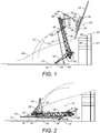
- FIGURE 1 there is shown the pipe handling apparatus 10 in accordance with the preferred embodiment of the present invention.
- the pipe handling apparatus 10 is mounted on a skid 12 that is supported upon the bed 14 of a vehicle, such as a truck.
- the pipe handling apparatus 10 in particular includes a boom 16 that is pivotally movable between a first position and a second position.
- FIGURE 1 an intermediate position of the pipe handling apparatus 10 is particularly shown. In this position, the pipe 18 is illustrated in its position prior to installation on the drill rig 20.
- a lever assembly 22 is pivotally connected to the boom 16.
- An arm 24 is pivotally connected to an end of the lever assembly 22 opposite the boom 16.
- a gripping means 26 is fixedly connected to an opposite end of the arm 24 opposite the lever assembly 22.
- the gripping means 26 includes a body 28 and grippers 30 and 32.
- a link 34 has one end pivotally connected to the skid 12 and an opposite end pivotally connected to the end of the lever assembly 22 opposite the arm 24.
- a brace 36 is pivotally connected to the boom 16 and also pivotally connected to the arm 24 between the lever assembly 22 and the body 28 of gripping means 26.
- the boom 16 is a structural framework of struts, cross members and beams.
- the boom 16 is configured so as to have an open interior such that the pipe 18 will be able to lifted in a manner so as to pass through the interior of the boom 16.
- the end 38 of the boom 16 should be strongly reinforced so as to provide the necessary structural integrity to the boom 16.
- a lug 40 extends outwardly from one side of the boom 16. This lug 40 is suitable for pivotable connection to the lever assembly 22.
- the boom 16 is pivotally connected at the opposite end 42 to a location on the skid 12.
- the pivotable connection at end 42 of the boom 16 is located in offset relationship and above the pivotable connection 44 of the link 34 with the skid 12.
- a small frame member 46 extends outwardly from the side of the boom 16 opposite the link 34.
- This frame assembly 46 has a pivotable connection with the brace 36.
- the lever assembly 22 includes a first portion 48 and a second portion 50.
- the first portion 48 extends at an obtuse angle with respect to the second portion 50.
- the link 34 is pivotally connected to the end of the second portion 50 opposite the first portion 48.
- the arm 24 is pivotally connected to the end of the first portion 48 opposite the second portion 50.
- the lug 40 of the boom 16 is pivotally connected in an area generally between the first portion 48 and the second portion 50.
- the arm 24 has an end pivotally connected to the end of the first portion 48 of the lever assembly 22.
- the opposite end of the arm 24 is connected to the gripping means 26.
- a pair of pin connections engage a surface of the body 28 of the gripping means 26 so as to fixedly position the gripping means 26 with respect to the end of the arm 24.
- the pin connections 52 and 54 can be in the nature of bolts, or other fasteners, so as to strongly connect the body 28 of gripping means 26 with the arm 24.
- the bolts associated with pin connections 52 and 54 can be removed such that other gripping means 26 can be affixed to the end of the arm 24.
- the pipe handling apparatus 10 of the present invention can be adaptable to various sizes of pipe 18 and various heights of drilling rigs 20.
- the gripping means 26 includes the body 28 with the grippers 30 and 32 translatable along the length of the body 28. This vertical translation of the grippers 30 and 32 allows the pipe 18 to be properly moved upwardly and downwardly once the vertical orientation of the pipe 18 is achieved.
- the grippers 30 and 32 are in the nature of conventional grippers which can open and close so as to engage the outer diameter of the pipe 18, as desired.
- the link 34 is a elongate member that extends from the pivotable connection 44 to the pivotable connection 68 of the second portion 50 of the lever assembly 22.
- the link 34 is non-extensible and extends generally adj acent to the opposite side from the boom 16 from that of the arm 24.
- the link 34 will generally move relative to the movement of the boom 16.
- the brace 36 is pivotally connected to the small framework 46 associated with boom 16 and also pivotally connected at a location along the arm 26 between the ends thereof. Brace 36 provides structural support to the arm 24 and also facilitates the desired movement of the arm 24 during the movement of the pipe 18 between the horizontal orientation and the vertical orientation.
- Actuators 56 and 58 are illustrated as having one end connected to the skid 12 and an opposite end connected to the boom 16 in a location above the end 42. When the actuators 56 and 58 are activated, they will pivot the boom 16 upwardly from the horizontal orientation ultimately to a position beyond vertical so as to cause the pipe 18 to achieve is vertical orientation.
- a single hydraulic actuator can be utilized instead of the pair of hydraulic actuators 56 and 58, as illustrated in FIGURE 1 .
- the drilling rig 20 is illustrated as having drill pipes 60 and 62 extending upwardly so as to have an end above the drill floor 64.
- the translatable movement of the grippers 30 and 32 can be utilized so as to cause the end of the pipe 18 to engage with the box of one of the drill pipes 60 and 62.
- FIGURE 1 the general movement of the bottom end of the pipe 18 is illustrated by line 66.
- the movement of the pivot point 68 of the connection between the lever assembly 22 and the link 34 is illustrated by line 70.
- Curved line 72 illustrates the movement of the pivotable connection 40 between the boom 16 and the lever assembly 22.
- the coordinated movement of each of the non-extensible members of the apparatus 10 is achieved with proper sizing and angular relationships.
- the present invention provides a four-bar link between the various components.
- the movement of the drill pipe 18 between a horizontal orientation and a vertical orientation can be achieved purely through the mechanics associated with the various components.
- only a single hydraulic actuator may be necessary so as to achieve this desired movement.
- the hydraulic actuators are only used for the pivoting of the boom. Since the skid 12 is located on the bed of a vehicle 14, the vehicle 14 can be maneuvered into place so as to properly align with the centerline of the drill pipe 60 and 62 of the drilling rig 20.
- the apparatus 10 can be operated so as to effectively move the drill pipe to its desired position.
- the gripper assemblies of the present invention allow the drill pipe 18 to be moved upwardly and downwardly for the proper stabbing of the drill pipes 60 and 62.
- the present invention is adaptable to various links of pipe 18.
- gripping means 26 can be installed on the end of the arm 24 so as to proper accommodate longer lengths of pipe 18. These variations are illustrated herein in connections FIGURES 6 - 9 .
- the present invention achieves it results by simple maneuvering of the vehicle 14, along with operation of the hydraulic cylinders 56 and 58. All other linkages and movement of the pipe 18 are achieved purely because of the mechanical connections between the various components. As such, the present invention assures a precise, self-centering of the pipe 18 with respect to the desired connecting pipe. This is accomplished with only a single degree of freedom in the pipe handling system.
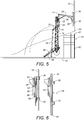
- FIGURE 2 illustrates the drill pipe 18 in a generally horizontal orientation.
- the drill pipe can be delivered to the apparatus 10 in a position below the boom 16.
- the drill pipe can be loaded upon the skid 12 in a location generally adjacent to the grippers 30 and 32 associated with the gripping means 26.
- the present invention facilitates the easy delivery of the drill pipe to the desired location.
- the gripper 30 and 32 will grip the outer diameter of the pipe 18 in this horizontal orientation.
- FIGURE 2 it can be seen that the boom 16 resides above the drill pipe 18 and in generally parallel relationship to the top surface of the skid 12.
- the lever assembly 22 is suitably pivoted so that the arm 24 extends through the interior of the framework of the boom 16 and such that the gripping means 26 engages the pipe 18.
- the brace 36 resides in connection with the small framework of the boom 16 and also is pivotally connected to the arm 24.
- the link 34 will reside below the boom 16 generally adjacent to the upper surface of the skid 12 and is connected to the second portion 50 of the lever assembly 22 below the boom 16.
- FIGURE 3 shows an intermediate position of the drill pipe 18 during the movement f the horizontal orientation to the vertical orientation.
- the gripping means 26 has engaged with the pipe 18.
- the lever assembly 22 is pivoting so that the end 70 of pipe 18 will pass through the interior of the framework of the boom 16.
- the arm associated with the gripping means 26 serves to move the body 28 of the gripping means 26 through the interior of the framework of the boom 16.
- the brace 36 is pulling on the first portion 48 of lever assembly 22 so as cause this motion to occur.
- the link 34 is pulling on the end of the second portion 50 of the lever assembly 22 so as to draw the first portion 48 upwardly and to cause the movement of the body 28 of the gripping means 26.
- the hydraulic actuators 56 and 58 have been operated so as to urge the boom 16 pivotally upwardly.
- FIGURE 4 shows a further intermediate movement of the drill pipe 18.
- the hydraulic actuators 56 and 58 urge the boom 16 angularly upwardly away from the top surface of the skid 12.
- This causes the link 34 to have a pulling force on the pivotal connection 68 of the second portion 50 of the lever assembly 22.
- This causes the first portion 48 of the lever assembly 22 to move upwardly thereby causing the arm 24, in combination with the brace 36 to lift the gripping means 26 further upwardly and draw the pipe 18 completely through the interior of the boom 16.
- the relative size and relation of the various components of the present invention achieve the movement of the pipe 18 without the need for separate hydraulic actuators.
- FIGURE 5 illustrates the drill pipe 18 in its vertical orientation.
- the drill pipe 18 is positioned directly above the underlying pipe 62 on the drilling rig 20.
- the further upward pivotal movement of the boom 16 is caused by the hydraulic cylinders 56 and 58.
- This causes the link 34 to rotate and draw the end of the second portion 50 of the lever assembly 22 downwardly.
- the lever assembly 22 rotates about the pivot point 40 such that the first portion 48 of the lever assembly 22 has a pivot 72 at its upper end.
- the brace 36 is now rotated in a position so as to provide support for the arm 24 in this upper position.
- the gripping means 26 has the gripper 30 and 32 aligned vertically and in spaced parallel relationship to each other.
- the vehicle 14 can be moved slightly so as to achieve further precise movement.
- the drill pipe 18 has achieved a completely vertical orientation by virtue of the interrelationship of the various components of the present invention and without the need for complex control mechanisms and hydraulics.
- the gripper 30 and 32 In order to install the drill pipe 18 upon the pipe 62, it is only necessary to vertically translate the gripper 30 and 32 within the body 28 of the gripping means 26. As such, the end 80 can be stabbed into the box connection 82 of pipe 62. Suitable tongs, spinner, or other mechanisms can be utilized so as to rotate the pipe 18 in order to achieve a desired connection. The gripper 30 and 32 can then be released from the exterior of the pipe 18 and returned back to the original position such that another length of drill pipe can be installed.
- FIGURE 6 is a detailed view of the gripping means 26 of the present invention.
- the pin connections 52 and 54 have been installed into alternative holes formed on the body 28 of the gripping means 26.
- the holes, such as hole 84 can be formed in a surface of the body 28 so as to allow selective connection between the end of the arm 24 and the body 28 of gripping means 26. As such, the position of the gripping means 26 in relation to the arm 24 can be adapted to various circumstances.
- the pipe 18 is engaged by gripper 30 and 32 of the gripping means 26.
- the configuration of the gripper 30 and 32, as shown in FIGURE 6 is particularly designed for short length (approximately 30 feet) of drill pipe.
- the gripper 30 and 32 is translated relative to the body 28 so as to lower end 80 of pipe 18 downwardly for connection to an underlying pipe.
- FIGURE 7 it can be seen that the drill pipe 18 is formed of separate sections 90, 92, 94 and 96 that are joined in end-to-end connection so as to form an extended length of the of the pipe 18.
- the gripping means 26 of the present invention will have to be adapted so as to accommodate such extended lengths.
- the structure of the apparatus 10 of the present invention can accommodate such an arrangement.
- the arm 24 is connected to a first gripper assembly 100 and connected by stab frame 102 to a second gripper assembly 104.
- the second gripper assembly 104 is located directly below and vertically aligned with the first gripper assembly 100.
- the stab frame 102 includes a suitable pin connection for engaging the body 106 of the second gripper assembly 104.
- the first gripper assembly 100 has body 108 that is directly connected to the pin connections associated with the arm 24.
- the gripping assembly 100 includes grippers 110 and 112 which engage in intermediate position along the length of pipe 18.
- the grippers 114 and 116 of the second gripper assembly 104 engage the lower portion of the pipe 18. The method of moving the pipe 18 from the horizontal position to the vertical position is similar to that described hereinbefore.
- the arm 24 can extend at various angles with respect to the gripper assembly. In the preferred embodiment, the arm 24 will be generally transverse to the length of the body associated with the gripper assemblies. However, if needed to accommodate certain drilling rig height and arrangements, the arm 24 can be angled up to 30° from transverse with respect to the body associated with the gripper assembly.
- the arm 24 has a first stab frame 120 extending upwardly from the top of the arm 24 and a second stab frame 122 extending below the arm 24.
- the stab frame120 includes a gripper assembly 124 affixed thereto.
- the stab frame 122 includes a gripper assembly 126 connected thereto.
- the arm 24 will include suitable pin connections located on the top surface thereof and on the bottom surface thereof so as to engage with the stab frames 120 and 122.
- the gripper assembly 124 has suitable grippers 128 and 130 for engaging an upper portion of the pipe 132.
- the gripper assembly 126 includes grippers 134 and 136 for engaging with a lower portion of the pipe 132.
- the pipe 132 is a multiple section pipe. However, pipe 132 can be an extended length of a single pipe section.
- FIGURE 9 shows still another embodiment of the gripper assembly structure of the present invention.
- the arm 24 is connected to the upper stab frame 150 and to the lower stab frame 152.
- Gripping assemblies 154, 156 and 158 are provided.
- the gripper assembly 154 is connected to an upper end of the upper stab frame 150.
- the gripper assembly 158 is connected to a lower end of the lower stab frame152.
- the gripper assembly 156 is intermediately located directly on the opposite side of the end of the arm 24 and connected to the lower end of the upper stab frame 150 and to the upper end of the lower stab frame 152.
- the present invention provides up to three gripper assemblies to be connected. This can be utilized so as to accommodate even longer lengths of pipe, if needed.
- the present invention achieves a number of advantages over the prior art. Most importantly, the present invention provides a pipe handling apparatus and method that minimizes the number of control mechanisms, sensors and hydraulic systems associated with the pipe handling system. Since the movement of the pipe is achieved in a purely mechanical way, only a single hydraulic actuator is necessary for the movement of the boom. All of the other movements are achieved by the interrelationship of the various components. As such, the present invention achieves freedom from the errors and deviations that can occur through the use of multiple hydraulic systems. The simplicity of the present invention facilitates the ability of a relatively unskilled worker to operate the pipe handling system. The amount of calibration is relatively minimal.
- the pipe handling apparatus of the present invention is independent of the drilling rig. As such, a single pipe handling apparatus that is built in accordance with the teachings of the present invention can be utilized on a number of rigs and can be utilized at any time when required. There is no need to modify the drilling rig, in any way, to accommodate the pipe handling apparatus of the present invention. Since the pipes are loaded beneath the boom, the providing of the pipe to the pipe handling apparatus can be achieved in a very simple manner. There is no need to lift the pipes to a particular elevation or orientation in order to initiate the pipe handling system.
Landscapes
- Engineering & Computer Science (AREA)
- Life Sciences & Earth Sciences (AREA)
- Geology (AREA)
- Mining & Mineral Resources (AREA)
- Mechanical Engineering (AREA)
- Physics & Mathematics (AREA)
- Environmental & Geological Engineering (AREA)
- Fluid Mechanics (AREA)
- General Life Sciences & Earth Sciences (AREA)
- Geochemistry & Mineralogy (AREA)
- Earth Drilling (AREA)
- Gripping Jigs, Holding Jigs, And Positioning Jigs (AREA)
Description
- The present invention relates to a tubular or pipe handling apparatus. More particularly, the present invention relates to a pipe handling apparatus for moving a pipe from a horizontal orientation to a vertical orientation. Additionally, the present invention relates to pipe handling apparatus for installing pipes upon a drilling rig. The present invention also relates to pipe handling apparatus that moves the pipe with a single degree of freedom.
- Drill rigs have utilized several methods for transferring tubular members from a pipe rack adjacent to the drill floor to a mousehole in the drill floor or the well bore for connection to a previously transferred tubular or tubular string. The term "tubular" or "pipe" as used herein includes all forms of drill pipe, drill collars, casing, liner, bottom hole assemblies (BHA), and other types of tubulars known in the art.
- Conventionally, drill rigs have utilized a combination of the rig cranes and the traveling system for transferring a tubular from the pipe rack to a vertical position above the center of the well. The obvious disadvantage with the prior art systems is that there is a significant manual involvement in attaching the pipe elevators to the tubular and moving the pipe from the drill rack to the rotary table. This manual transfer operation in the vicinity of workers is potentially dangerous and has caused numerous injuries in drilling operations. Further, the hoisting system may allow the tubular to come into contact with the catwalk or other portions of the rig as the tubular is transferred from the pipe rack to the drill floor. This can damage the tubular and may affect the integrity of the connections between successive tubulars in the well.
- One method of transferring pipe from the rack to the well platform comprises tying one end of a line on the rig around a selected pipe on the pipe rack. The pipe is thereafter lifted up onto the platform and the lower end thereof is placed into the mousehole. The mousehole is simply an upright, elongate cylindrical container adjacent the rotary table which supports the pipe temporally. When it is necessary to add the pipe to the drill string, slips are secured about the drill string on the rotary table thereby supporting the same in the well bore. The pipe is disconnected from the traveling equipment and the elevators, or the kelly, are connected to the pipe in the mousehole. Next, the traveling block is raised thereby positioning the pipe over the drill string and tongs are used to secure the pipe to the upper end of the drill string. The drill pipe elevators suspend the drill pipe from a collar which is formed around one end of the pipe and do not clamp the pipe thereby permitting rotational pipe movement in order to threadably engage the same to the drill string.
- A prior art technique for moving joints of casing from racks adjacent to the drilling rig comprises tying a line from the rig onto one end of a selected casing joint on the rack. The line is raised by lifting the casing joint up a ramp leading to the rig platform. As the rope lifts the casing from the rack, the lower end of the casing swings across the platform in a dangerous manner. The danger increases when a floating system is used in connection with drilling. Since the rope is tied around the casing at one end thereof, the casing does not hang vertically, but rather tilts somewhat. A man working on a platform elevated above the rig floor must hold the top of the casing and straighten it out while the casing is threaded into the casing string which is suspended in the well bore by slips positioned on the rotary table.
- It would be desirable to be able to grip casing or pipe positioned on a rack adjacent a drilling well, move the same into vertical orientation over the well bore, and thereafter lower the same onto the string suspended in the well bore.
- In the past, various devices have been created which mechanically move a pipe from a horizontal orientation to a vertical orientation such that the vertically oriented pipe can be installed into the well bore. Typically, these devices have utilized several interconnected arms that are associated with a boom. In order to move the pipe, a succession of individual movements of the levers, arms, and other components of the boom must be performed in a coordinated manner in order to achieve the desired result. Typically, a wide variety of hydraulic actuators are connected to each of the components so as to carry out the prescribed movement. A complex control mechanism is connected to each of these actuators so as to achieve the desired movement. Advanced programing is required of the controller in order to properly coordinate the movements in order to achieve this desired result.
- Unfortunately, with such systems, the hydraulic actuators, along with other components, can become worn with time. Furthermore, the hydraulic integrity of each of the actuators can become compromised over time. As such, small variations in each of the actuators can occur. These variations, as they occur, can make the complex mechanism rather inaccurate. The failure of one hydraulic component can exacerbate the problems associated with the alignment of the pipe in a vertical orientation. Adjustments of the programing are often necessary to as to continue to achieve the desired results. Fundamentally, the more hydraulic actuators that are incorporated into such a system, the more likely it is to have errors, inaccuracies, and deviations in the desired delivery profile of the tubular. Typically, very experienced and knowledgeable operators are required so as to carry out this pipe movement operation. This adds significantly to the cost associated with pipe delivery.
- In the past, various patents have issued relating to such pipe handling devices. For example,
U.S. Patent No. 3,177,944, issued on April 13, 1965 to R.N. Knight , describes a racking mechanism for earth boring equipment that provides for horizontal storage of pipe lengths on one side of and clear of the derrick. This is achieved by means of a transport arm which is pivoted toward the base of the derrick for swing movement in a vertical plane. The outer end of the arm works between a substantially vertical position in which it can accept a pipe length from, or deliver a pipe length to, a station in the derrick, and a substantially horizontal portion in which the arm can deliver a pipe length to, or accept a pipe length from, a station associated with storage means on one side of the derrick. -
U.S. Patent No. 3,464,507, issued on September 2, 1969 to E.L. Alexander et al. , teaches a portable rotary pipe handling system. This system includes a mast pivotally mounted and movable between a reclining transport position to a desired position at the site drilling operations which may be at any angle up to vertical. The mast has guides for a traveling mechanism that includes a block movable up and down the mast through operation of cables reeved from the traveling block over crown block pulleys into a drawwork. A power drill drive is carried by the traveling block. An elevator for drill pipe is carried by arm swingably mounted relative to the power unit. Power tongs, slips, and slip bushings are supported adjacent the lower end of the mast and adapted to have a drill pipe extend therethrough from a drive bushing connected to a power drive whereby the drill pipe is extended in the direction of the hole to be drilled. -
U.S. Patent No. 3,633,771 issued on January 11, 1972 to Woolslayer et al. , discloses an apparatus for moving drill pipe into and out of an oil well derrick. A stand of pipe is gripped by a strongback which is pivotally mounted to one end of a boom. The boom swings the strongback over the rotary table thereby vertically aligning the pipe stand with the drill string. When both adding pipe to and removing pipe from the drill string, all vertical movement of the pipe is accomplished by the elevator suspended from the traveling block. -
U.S. Patent No. 3,860,122, issued on January 14, 1975 to L.C. Cernosek , describes an apparatus for transferring a tubular member, such as a pipe, from a storage area to an oil well drilling platform. The positioning apparatus includes a pipe positioner mounted on a platform for moving the pipe to a release position whereby the pipe can be released to be lowered to a submerged position. A load means is operably attached or associated with the platform and positioning means in order to move the pipe in a stored position to a transfer position in which the pipe is transferred to the positioner. The positioner includes a tower having pivotally mounted thereon a pipe track with a plurality of pipe clamp assemblies which are adapted to receive a pipe length. The pipe track is pivotally movable by hydraulic power means or gear means between a transfer position in which pipe is moved into the plurality of clamp assemblies and the release position in which the pipe is released for movement to a submerged position. -
U.S. Patent No. 3,986,619, issued on October 19, 1976 to Woolslayer et al. , shows a pipe handling apparatus for an oil well drilling derrick. In this apparatus the inner end of the boom is pivotally supported on a horizontal axis in front of a well. A clamping means is pivotally connected to the outer end of the boom on an axis parallel to the horizontal axis at one end. The clamping means allows the free end of the drill pipe to swing across the boom as the outer end of the boom is raised or lowered. A line is connected at one end with the traveling block that raises and lowers the elevators and at the other end to the boom so as to pass around sheaves. -
U.S. Patent No. 4,172,684 issued on October 30, 1979 to C. Jenkins , shows a floor level pipe handling apparatus which is mounted on the floor of an oil well derrick suitable structure. This apparatus includes a support that is rockable on an axis perpendicular to the centerline of a well being drilled. One end of an arm is pivotally mounted on the support on an axis transverse to the centerline of the well. The opposite end of the arm carries a pair of shoes having laterally opening pipe-receiving seats facing away from the arm. The free end of the arm can be swung toward and away from the well centerline and the arm support can be rocked to swing the arm laterally. -
U.S. Patent No. 4,403,666 issued on September 13, 1983 to C.A. Willis , shows self-centering tongs and a transfer arm for a drilling apparatus. The clamps of the transfer arm are resiliently mounted to the transfer arm so as to provide limited axial movement of the clamps and thereby of a clamped down hole tubular. A pair of automatic, self-centering, hydraulic tongs are provided for making up and breaking out threaded connections of tubulars. -
U.S. Patent No. 4,407,629, issued on October 4, 1983 to C.A. Willis , teaches a lifting apparatus for downhole tubulars. This lifting apparatus includes two rotatably mounted clamps which are rotatable between a side loading-position so as to facilitate the loading and unloading in the horizontal position, and a central position, in which a clamped tubular is aligned with the drilling axis when the boom is in the vertical position. An automatic hydraulic sequencing circuit is provided to automatically rotate the clamps into the side-loading position whenever the boom is pivoted with a down-hole tubular positioned in the clamp. In this position, the clamped tubular is aligned with a safety plate mounted on the boom to prevent a clamped tubular from slipping from the clamps. -
U.S. Patent No. 4,492,501 provides a platform positioning system for a drilling operation which includes a support structure and a transfer arm pivotally connected to the support structure to rotate about a first axis. This platform positioning system includes a platform which is pivotally connected to the support structure to rotate about a second axis, and rod which is mounted between the transfer arm and the platform. The position of the arm and platform axes and the length of the rod are selected such that the transfer arm automatically and progressively raises the platform to the raised position by means of the rod as the transfer arm moves to the raised position. The transfer arm automatically and progressively lowers the platform to the lowered position by means of the rod as the transfer arm moves to the lowered position. -
U.S. Patent No. 4,595,066 issued on June 17, 1986 to Nelmark et al. , provides an apparatus for handling drill pipes and used in association with blast holes. This system allows a drill pipe to be more easily connected and disconnected to a drill string in a hole being drilled at an angle. A receptacle is formed at the lower end of the carrier that has hydraulically operated doors secured by a hydraulically operated lock. A gate near the upper end is pneumatically operated in response to the hydraulic operation of the receptacle lock. -
U.S. Patent No. 4,822,230 issued on April 18, 1989 to P. Slettedal , teaches a pipe handling apparatus which is adapted for automated drilling operations. Drill pipes are manipulated between substantially horizontal and vertical positions. The apparatus is used with a top mounted drilling device which is rotatable about a substantially horizontal axis. The apparatus utilizes a strongback provided with clamps to hold and manipulate pipes. The strongback is rotatably connected to the same axis as the drilling device. The strongback moves up or down with the drilling device. A brace unit is attached to the strongback to be rotatable about a second axis. -
U.S. Patent No. 4,834,604 issued on May 30, 1989 to Brittain et al. , provides a pipe moving apparatus and method for moving casing or pipe from a horizontal position adjacent a well to a vertical position over the well bore. The machine includes a boom movable between a lowered position and a raised position by a hydraulic ram. A strongback grips the pipe and holds the same until the pipe is vertically positioned. Thereafter, a hydraulic ram on the strongback is actuated thereby lowering the pipe or casing onto the string suspended in the well bore and the additional pipe or casing joint is threaded thereto. -
U.S. Patent No. 4,708,581 issued on November 24, 1987 H.L. Adair , provides a method for positioning a transfer arm for the movement of drill pipe. A drilling mast and a transfer arm is mounted at a first axis adjacent the mast to move between a lowered position near ground level and an upper position aligned with the mast. A reaction point anchor is fixed with respect to the drilling mast and spaced from the first axis. A fixed length link is pivotably mounted to the transfer arm at a second axis, spaced from the first axis, and a first single stage cylinder is pivotably mounted at one end to the distal end of the link and at the other end to the transfer arm. A second single stage hydraulic cylinder is pivotably mounted at one end to the distal end of the link and at the other end to the reaction point. -
U.S. Patent No. 4,759,414 issued on July 26,1988 to C.A. Willis , provides a drilling machine which includes a drilling superstructure skid which defines two spaced-apart parallel skid runners and a platform. The platform supports a drawworks mounted on a drawworks skid and a pipe boom is mounted on a pipe boom skid sized to fit between the skid runners of the drilling substructure skid. The drilling substructure skid supports four legs which, in turn, support a drilling platform on which is mounted a lower mast section. The pipe boom skid mounts a pipe boom as well as a boom linkage, a motor, and a hydraulic pump adapted to power the pipe boom linkage. Mechanical position locks hold the upper skid in relative position over the lower skid. -
U.S. Patent No. 5,458,454 issued on October 17, 1995 to R.S. Sorokan , describes a pipe handling method which is used to move tubulars used from a horizontal position on a pipe rack adjacent the well bore to a vertical position over the wall center. This method utilizes bicep and forearm assemblies and a gripper head for attachment to the tubular. The path of the tubular being moved is close to the conventional path of the tubular utilizing known cable transfer techniques so as to allow access to the drill floor through the V-door of the drill rig.U.S. Patent No. 6,220,807 describes apparatus for carrying out the method ofU.S. Patent No. 5,458,454 . -
U.S. Patent No. 6,609,573 issued on August 26, 2003 to H.W.F. Day , teaches a pipe handling system for an offshore structure. The pipe handling system transfers the pipes from a horizontal pipe rack adjacent to the drill floor to a vertical orientation in a set-back area of the drill floor where the drill string is made up for lowering downhole. The cantilevered drill floor is utilized with the pipe handling system so as to save platform space. -
U.S. Patent No. 6,705,414 issued on March 16, 2004 to Simpson et al , describes a tubular transfer system for moving pipe between a substantial horizontal position on the catwalk and a substantially vertical position at the rig floor entry. Bundles of individual tubulars are moved to a process area where a stand make-up/break-out machine makes up the tubular stands. The bucking machine aligns and stabs the connections and makes up the connection to the correct torque. The tubular stand is then transferred from the machine to a stand storage area. A trolley is moved into position over the pick-up area to retrieve the stands. The stands are clamped to the trolley and the trolley is moved from a substantially horizontal position to a substantially vertical position at the rig floor entry. A vertical pipe-racking machine transfers the stands to the traveling equipment. The traveling equipment makes up the stand connection and the stand is run into the hole. -
U.S. Patent No. 6,779,614 issued on August 24, 2004 to M.S. Oser , shows another system and method for transferring pipe. A pipe shuttle is used for moving a pipe joint into a first position and then lifting upwardly toward an upper second position. -
WO 2006/038790 A1 furthermore discloses a tubular handling apparatus for moving tubulars between a substantially horizontal transfer station and a second transfer station. This document forms a prior art closest to the subject-matter of claim 1 and discloses a pipe handling apparatus comprising a boom pivotally movable between a generally horizontal fist position and a second position; a lever assembly pivotally connected to the boom, the lever assembly having a first portion extending outwardly at an angle with respect to a second portion; an arm pivotally connected at one end to the first portion of the lever assembly and extending outwardly therefrom; a pipe gripper means affixed to an opposite end of the arm; a link pivotally connected to the second portion of the lever assembly, the link pivotable at an end of the second portion opposite of the first portion so as to move relative to the movement of the boom between the first and second positions; and a brace having a one end pivotally connected to the boom. -
US 4759414 A discloses a drilling machine including a drilling substructure skid which defines two spaced parallel skid runners and a platform. The platform supports a draw works mounted on a draw works skid, and a pipe boom is mounted on a pipe boom skid sized to fit between the skid runners of the drilling substructure skid.US 3995746 A discloses a hydraulic crane including a pair of boom arms and a pair of swing arms pivotally connected in association with a pair of auxiliary arms and arranged in the form of a pantograph.US 4834604 A discloses a machine for moving casing or a pipe from a horizontal position adjacent a well to a vertical position over the well bore. The machine includes a boom movable between a lowered position and a raised position by a hydraulic ram. - It is an object of the present invention to provide a pipe handling apparatus and method which minimizes the amount of calibration required in order to move the pipe from a horizontal orientation to a vertical orientation.
- It is another object of the present invention to provide a pipe handling apparatus which operates with a single degree of freedom so as to move the pipe without adjustments between the components.
- It is another object of the present invention to provide a pipe handling apparatus and method that can be transported on a skid or on a truck.
- It is another object of the present invention to provide a pipe handling apparatus and method which allows for the self-centering of the pipe.
- It is another object of the present invention to provide a pipe handling apparatus and method which can be utilized independent of the existing rig.
- It is still a further object of the present invention to provide a pipe handling apparatus and method which avoids the use of multiple hydraulic cylinders and actuators.
- It is still another object of the present invention to provide a pipe handling apparatus and method which minimizes the amount of instrumentation and controls utilized for carrying out the pipe handling activities.
- It is still another object of the present invention to provide a pipe handling apparatus and method which allows for the pipe to be loaded beneath the lifting boom.
- It is still a further object of the present invention to provide a pipe handling apparatus and method which is of minimal cost and easy to use.
- It is still a further object of the present invention to provide a pipe handling apparatus and method which allows relatively unskilled workers to carry out the pipe handling activities.
- These and other objects and advantages of the present invention will become apparent from a reading of the attached specification and appended claims.
- The present invention is a pipe handling apparatus according to claim 1 that comprises a boom that is pivotally movable between a first position and a second position, a lever assembly pivotally connected to the boom, an arm pivotally connected at one end to the lever assembly and extending outwardly therefrom, a gripper means affixed to an opposite end of the arm suitable for gripping a diameter of the pipe, a link pivotally connected to the lever assembly and pivotable at an end of the second portion opposite of the first portion so as to move relative to the movement of the boom between the first and second positions, and a brace having a one end pivotally connected to the boom and an opposite end pivotally connected to the arm between the ends of the arm. The lever assembly has a first portion extending outwardly at an obtuse angle with respect to the second portion. The arm is pivotally connected at one end to the first portion of the lever assembly. The link is pivotally connected to the end of the second portion of the lever assembly. Each of the brace, the link, the arm and the lever assembly are non-extensible items. Since the components are generally arranged in a common plane, there is only one degree of freedom between the components. As such, pipe can be moved from the loading position to the installation position without any other adjustment between the components.
- In the present invention, the first position of the boom is generally horizontal. The gripper means will have a vertical orientation when the boom is in the second position.
- A skid extends in a horizontal orientation and is positioned below the boom. The boom is pivotally mounted upon the skid. A vehicle having a bed can be utilized so as to receive the skid thereon. The end of the link opposite the second portion of the lever is pivotally mounted upon the skid in a position offset from and below the pivotal mounting of the boom upon the skid.
- In the present invention a pipe will extend in a horizontal orientation upon this skid. The gripper means faces the pipe when the boom is in the first position. This gripper means is positioned below the boom when the boom is in the first position.
- The boom has a lug extending outwardly from a side thereof. The lever assembly is pivotally mounted to the lug in a position where the first portion of the lever assembly joins the second portion of the lever assembly. The lug extends outwardly from a side of the boom opposite the link.
- The gripper means is fixedly mounted to the opposite end of the arm. In particular, the gripper means includes a body lug having a surface affixed to the opposite end of the arm, a first gripper extending outwardly of the body on an opposite side of the arm, and a second gripper extending outwardly of the body on the side opposite the arm and in spaced relation to the first gripper. The first and second grippers are translatable along the body. The body has mounting means thereon for selectively positioning the body in fixed relation to the arm. The arm can extend between transverse and 30° offset from transverse relative to the body.
- An actuating means is mounted at one end to the skid and an opposite end to the boom at a location offset from the pivotal mounting of the boom to the skid. This actuating means serves to move the boom between the first and second positions. In the preferred embodiment, this actuating means is a hydraulic cylinder that can be suitably operated so as to move the boom between the positions. In the present invention, the entire movement of the drilling pipe from the horizontal position to the vertical position is accomplished solely by the use of the actuating means connected between the skid and the boom.
- The present invention is also a method of moving a pipe from a horizontal orientation, using the pipe handling apparatus of claim 1. This method comprises the steps of: 1) extending a boom over the horizontally orientated pipe such that grippers are positioned adjacent to the horizontally orientated pipe; 2) gripping the horizontally orientated pipe with the grippers, and 3) pivoting the boom upwardly such that the pipe is moved angularly through an interior of the boom until the pipe is in a vertical orientation. The arm is connected to an opposite end of a non-extensible link. This link is movable in relation to the boom. A brace is pivotally mounted at one end to the boom and at an opposite end to the arm. The angular movement of the pipe is solely caused by the connections of the boom with the arm, the link and the brace. The method of the present invention also includes vertically translating the grippers along the body such that the pipe moves vertically into a desired position. Specifically, this step involves stabbing a underlying pipe with an end of the pipe by the vertical translation of the pipe. The grippers can then be released from the pipe. An actuator is connected to the boom in a position above a bottom of the bottom of the boom. The step of pivoting includes actuating the actuator so as to cause the boom to pivot upwardly from the horizontal orientation until the boom extends beyond a vertical orientation.
-
-
FIGURE 1 is a side elevation view showing the pipe handling apparatus in accordance with the teachings of the preferred embodiment of the present invention. -
FIGURE 2 is a side elevational view showing the pipe handling apparatus of the present invention in a first position. -
FIGURE 3 is a side elevational view showing the pipe handling apparatus moving from the first position toward the second position. -
FIGURE 4 is a side elevation view of the pipe handling apparatus showing the pipe handling apparatus as moving the pipe further to the second position. -
FIGURE 5 is a side elevational view showing the pipe handling apparatus in its second position in which the pipe extends in a vertical orientation. -
FIGURE 6 is an illustration of the gripper assembly as vertically translating the pipe. -
FIGURE 7 is a side elevational view of a first alternative embodiment of the gripper assembly of the present invention. -
FIGURE 8 is a side elevational view showing a second alternative embodiment of the gripper assembly of the present invention. -
FIGURE 9 is a side elevational view showing a third alternative embodiment of the gripper assembly of the present invention. - Referring to
FIGURE 1 , there is shown thepipe handling apparatus 10 in accordance with the preferred embodiment of the present invention. Thepipe handling apparatus 10 is mounted on askid 12 that is supported upon thebed 14 of a vehicle, such as a truck. Thepipe handling apparatus 10 in particular includes aboom 16 that is pivotally movable between a first position and a second position. InFIGURE 1 , an intermediate position of thepipe handling apparatus 10 is particularly shown. In this position, thepipe 18 is illustrated in its position prior to installation on thedrill rig 20. Alever assembly 22 is pivotally connected to theboom 16. Anarm 24 is pivotally connected to an end of thelever assembly 22 opposite theboom 16. A grippingmeans 26 is fixedly connected to an opposite end of thearm 24 opposite thelever assembly 22. The gripping means 26 includes abody 28 andgrippers link 34 has one end pivotally connected to theskid 12 and an opposite end pivotally connected to the end of thelever assembly 22 opposite thearm 24. Abrace 36 is pivotally connected to theboom 16 and also pivotally connected to thearm 24 between thelever assembly 22 and thebody 28 of grippingmeans 26. - Int the present invention, the
boom 16 is a structural framework of struts, cross members and beams. In particular, in the present invention, theboom 16 is configured so as to have an open interior such that thepipe 18 will be able to lifted in a manner so as to pass through the interior of theboom 16. As such, theend 38 of theboom 16 should be strongly reinforced so as to provide the necessary structural integrity to theboom 16. Alug 40 extends outwardly from one side of theboom 16. Thislug 40 is suitable for pivotable connection to thelever assembly 22. Theboom 16 is pivotally connected at theopposite end 42 to a location on theskid 12. The pivotable connection atend 42 of theboom 16 is located in offset relationship and above thepivotable connection 44 of thelink 34 with theskid 12. Asmall frame member 46 extends outwardly from the side of theboom 16 opposite thelink 34. Thisframe assembly 46 has a pivotable connection with thebrace 36. - The
lever assembly 22 includes afirst portion 48 and asecond portion 50. Thefirst portion 48 extends at an obtuse angle with respect to thesecond portion 50. Thelink 34 is pivotally connected to the end of thesecond portion 50 opposite thefirst portion 48. Thearm 24 is pivotally connected to the end of thefirst portion 48 opposite thesecond portion 50. Thelug 40 of theboom 16 is pivotally connected in an area generally between thefirst portion 48 and thesecond portion 50. This unique arrangement of thelever assembly 22 facilitates the ability of the present invention to carry out the movement of thepipe 18 between the horizontal orientation and the vertical orientation. - The
arm 24 has an end pivotally connected to the end of thefirst portion 48 of thelever assembly 22. The opposite end of thearm 24 is connected to the grippingmeans 26. In particular, a pair of pin connections engage a surface of thebody 28 of the gripping means 26 so as to fixedly position the gripping means 26 with respect to the end of thearm 24. Thepin connections body 28 of grippingmeans 26 with thearm 24. The bolts associated withpin connections arm 24. As such, thepipe handling apparatus 10 of the present invention can be adaptable to various sizes ofpipe 18 and various heights of drilling rigs 20. - The gripping means 26 includes the
body 28 with thegrippers body 28. This vertical translation of thegrippers pipe 18 to be properly moved upwardly and downwardly once the vertical orientation of thepipe 18 is achieved. Thegrippers pipe 18, as desired. - The
link 34 is a elongate member that extends from thepivotable connection 44 to thepivotable connection 68 of thesecond portion 50 of thelever assembly 22. Thelink 34 is non-extensible and extends generally adj acent to the opposite side from theboom 16 from that of thearm 24. Thelink 34 will generally move relative to the movement of theboom 16. Thebrace 36 is pivotally connected to thesmall framework 46 associated withboom 16 and also pivotally connected at a location along thearm 26 between the ends thereof.Brace 36 provides structural support to thearm 24 and also facilitates the desired movement of thearm 24 during the movement of thepipe 18 between the horizontal orientation and the vertical orientation. -
Actuators skid 12 and an opposite end connected to theboom 16 in a location above theend 42. When theactuators boom 16 upwardly from the horizontal orientation ultimately to a position beyond vertical so as to cause thepipe 18 to achieve is vertical orientation. Within the concept of the present invention, a single hydraulic actuator can be utilized instead of the pair ofhydraulic actuators FIGURE 1 . - The
drilling rig 20 is illustrated as havingdrill pipes drill floor 64. When thepipe 18 is in its vertical orientation, the translatable movement of thegrippers pipe 18 to engage with the box of one of thedrill pipes - In
FIGURE 1 , the general movement of the bottom end of thepipe 18 is illustrated byline 66. The movement of thepivot point 68 of the connection between thelever assembly 22 and thelink 34 is illustrated byline 70.Curved line 72 illustrates the movement of thepivotable connection 40 between theboom 16 and thelever assembly 22. - In the present invention, the coordinated movement of each of the non-extensible members of the
apparatus 10 is achieved with proper sizing and angular relationships. In essence, the present invention provides a four-bar link between the various components. As a result, the movement of thedrill pipe 18 between a horizontal orientation and a vertical orientation can be achieved purely through the mechanics associated with the various components. As can be seen, only a single hydraulic actuator may be necessary so as to achieve this desired movement. There does not need to be coordinated movement of hydraulic actuators. The hydraulic actuators are only used for the pivoting of the boom. Since theskid 12 is located on the bed of avehicle 14, thevehicle 14 can be maneuvered into place so as to properly align with the centerline of thedrill pipe drilling rig 20. Once the proper alignment is achieved by thevehicle 14, theapparatus 10 can be operated so as to effectively move the drill pipe to its desired position. The gripper assemblies of the present invention allow thedrill pipe 18 to be moved upwardly and downwardly for the proper stabbing of thedrill pipes pipe 18. - Various types of gripping
means 26 can be installed on the end of thearm 24 so as to proper accommodate longer lengths ofpipe 18. These variations are illustrated herein in connectionsFIGURES 6 - 9 . - As such, instead of the complex control mechanisms that are required with prior art systems, the present invention achieves it results by simple maneuvering of the
vehicle 14, along with operation of thehydraulic cylinders pipe 18 are achieved purely because of the mechanical connections between the various components. As such, the present invention assures a precise, self-centering of thepipe 18 with respect to the desired connecting pipe. This is accomplished with only a single degree of freedom in the pipe handling system. -
FIGURE 2 illustrates thedrill pipe 18 in a generally horizontal orientation. In the present invention, it is important to note that the drill pipe can be delivered to theapparatus 10 in a position below theboom 16. In particular, the drill pipe can be loaded upon theskid 12 in a location generally adjacent to thegrippers means 26. As such, the present invention facilitates the easy delivery of the drill pipe to the desired location. Thegripper pipe 18 in this horizontal orientation. - In
FIGURE 2 , it can be seen that theboom 16 resides above thedrill pipe 18 and in generally parallel relationship to the top surface of theskid 12. Thelever assembly 22 is suitably pivoted so that thearm 24 extends through the interior of the framework of theboom 16 and such that the grippingmeans 26 engages thepipe 18. Thebrace 36 resides in connection with the small framework of theboom 16 and also is pivotally connected to thearm 24. Thelink 34 will reside below theboom 16 generally adjacent to the upper surface of theskid 12 and is connected to thesecond portion 50 of thelever assembly 22 below theboom 16. -
FIGURE 3 shows an intermediate position of thedrill pipe 18 during the movement f the horizontal orientation to the vertical orientation. As can be seen, the grippingmeans 26 has engaged with thepipe 18. Thelever assembly 22 is pivoting so that theend 70 ofpipe 18 will pass through the interior of the framework of theboom 16. Also, the arm associated with the grippingmeans 26 serves to move thebody 28 of the gripping means 26 through the interior of the framework of theboom 16. Thebrace 36 is pulling on thefirst portion 48 oflever assembly 22 so as cause this motion to occur. Thelink 34 is pulling on the end of thesecond portion 50 of thelever assembly 22 so as to draw thefirst portion 48 upwardly and to cause the movement of thebody 28 of the grippingmeans 26. Thehydraulic actuators boom 16 pivotally upwardly. -
FIGURE 4 shows a further intermediate movement of thedrill pipe 18. Once again, thehydraulic actuators boom 16 angularly upwardly away from the top surface of theskid 12. This causes thelink 34 to have a pulling force on thepivotal connection 68 of thesecond portion 50 of thelever assembly 22. This causes thefirst portion 48 of thelever assembly 22 to move upwardly thereby causing thearm 24, in combination with thebrace 36 to lift the gripping means 26 further upwardly and draw thepipe 18 completely through the interior of theboom 16. As can be seen, the relative size and relation of the various components of the present invention achieve the movement of thepipe 18 without the need for separate hydraulic actuators. -
FIGURE 5 illustrates thedrill pipe 18 in its vertical orientation. As can be seen, thedrill pipe 18 is positioned directly above the underlyingpipe 62 on thedrilling rig 20. The further upward pivotal movement of theboom 16 is caused by thehydraulic cylinders link 34 to rotate and draw the end of thesecond portion 50 of thelever assembly 22 downwardly. Thelever assembly 22 rotates about thepivot point 40 such that thefirst portion 48 of thelever assembly 22 has apivot 72 at its upper end. Thebrace 36 is now rotated in a position so as to provide support for thearm 24 in this upper position. The gripping means 26 has thegripper bottom end 80 of thepipe 18 and the upper end 82 ofpipe 62, then thevehicle 14 can be moved slightly so as to achieve further precise movement. In the manner described hereinbefore, thedrill pipe 18 has achieved a completely vertical orientation by virtue of the interrelationship of the various components of the present invention and without the need for complex control mechanisms and hydraulics. - In order to install the
drill pipe 18 upon thepipe 62, it is only necessary to vertically translate thegripper body 28 of the grippingmeans 26. As such, theend 80 can be stabbed into the box connection 82 ofpipe 62. Suitable tongs, spinner, or other mechanisms can be utilized so as to rotate thepipe 18 in order to achieve a desired connection. Thegripper pipe 18 and returned back to the original position such that another length of drill pipe can be installed. -
FIGURE 6 is a detailed view of the gripping means 26 of the present invention. InFIGURE 6 thepin connections body 28 of the grippingmeans 26. The holes, such ashole 84 can be formed in a surface of thebody 28 so as to allow selective connection between the end of thearm 24 and thebody 28 of grippingmeans 26. As such, the position of the gripping means 26 in relation to thearm 24 can be adapted to various circumstances. - It can be seen that the
pipe 18 is engaged bygripper means 26. The configuration of thegripper FIGURE 6 , is particularly designed for short length (approximately 30 feet) of drill pipe. InFIGURE 6 , it can be seen that thegripper body 28 so as tolower end 80 ofpipe 18 downwardly for connection to an underlying pipe. - Occasionally, it is necessary to accommodate longer lengths of pipes. In other circumstances, it is desirable to accommodate pipes that are already assembled in an extended length. In
FIGURE 7 , it can be seen that thedrill pipe 18 is formed ofseparate sections pipe 18. When such pipe arrangements are required, the gripping means 26 of the present invention will have to be adapted so as to accommodate such extended lengths. Fortunately, the structure of theapparatus 10 of the present invention can accommodate such an arrangement. As can be seen inFIGURE 7 , thearm 24 is connected to afirst gripper assembly 100 and connected bystab frame 102 to asecond gripper assembly 104. Thesecond gripper assembly 104 is located directly below and vertically aligned with thefirst gripper assembly 100. Thestab frame 102 includes a suitable pin connection for engaging thebody 106 of thesecond gripper assembly 104. Thefirst gripper assembly 100 hasbody 108 that is directly connected to the pin connections associated with thearm 24. The grippingassembly 100 includesgrippers pipe 18. Thegrippers second gripper assembly 104 engage the lower portion of thepipe 18. The method of moving thepipe 18 from the horizontal position to the vertical position is similar to that described hereinbefore. - It should be noted that the
arm 24 can extend at various angles with respect to the gripper assembly. In the preferred embodiment, thearm 24 will be generally transverse to the length of the body associated with the gripper assemblies. However, if needed to accommodate certain drilling rig height and arrangements, thearm 24 can be angled up to 30° from transverse with respect to the body associated with the gripper assembly. - In
FIGURE 8 , it an be seen that thearm 24 has afirst stab frame 120 extending upwardly from the top of thearm 24 and asecond stab frame 122 extending below thearm 24. The stab frame120 includes agripper assembly 124 affixed thereto. Thestab frame 122 includes agripper assembly 126 connected thereto. Thearm 24 will include suitable pin connections located on the top surface thereof and on the bottom surface thereof so as to engage with the stab frames 120 and 122. Thegripper assembly 124 hassuitable grippers pipe 132. Thegripper assembly 126 includesgrippers pipe 132. As illustrated inFIGURE 8 , thepipe 132 is a multiple section pipe. However,pipe 132 can be an extended length of a single pipe section. -
FIGURE 9 shows still another embodiment of the gripper assembly structure of the present invention. InFIGURE 9 , thearm 24 is connected to theupper stab frame 150 and to thelower stab frame 152. Grippingassemblies gripper assembly 154 is connected to an upper end of theupper stab frame 150. The gripper assembly 158 is connected to a lower end of the lower stab frame152. Thegripper assembly 156 is intermediately located directly on the opposite side of the end of thearm 24 and connected to the lower end of theupper stab frame 150 and to the upper end of thelower stab frame 152. As such, the present invention provides up to three gripper assemblies to be connected. This can be utilized so as to accommodate even longer lengths of pipe, if needed. - The present invention achieves a number of advantages over the prior art. Most importantly, the present invention provides a pipe handling apparatus and method that minimizes the number of control mechanisms, sensors and hydraulic systems associated with the pipe handling system. Since the movement of the pipe is achieved in a purely mechanical way, only a single hydraulic actuator is necessary for the movement of the boom. All of the other movements are achieved by the interrelationship of the various components. As such, the present invention achieves freedom from the errors and deviations that can occur through the use of multiple hydraulic systems. The simplicity of the present invention facilitates the ability of a relatively unskilled worker to operate the pipe handling system. The amount of calibration is relatively minimal. Since the
skid 12 associated with the present invention can be transported by a truck, various fine movements and location of the pipe handling apparatus can be achieved through the simple movement of the vehicle. The pipe handling apparatus of the present invention is independent of the drilling rig. As such, a single pipe handling apparatus that is built in accordance with the teachings of the present invention can be utilized on a number of rigs and can be utilized at any time when required. There is no need to modify the drilling rig, in any way, to accommodate the pipe handling apparatus of the present invention. Since the pipes are loaded beneath the boom, the providing of the pipe to the pipe handling apparatus can be achieved in a very simple manner. There is no need to lift the pipes to a particular elevation or orientation in order to initiate the pipe handling system.
Claims (18)
- A pipe handling apparatus (10) comprising: a boom (16) pivotally movable between a first position and a second position, said first position of said boom (16) being generally horizontal;
a lever assembly (22) pivotally connected to said boom (16), said lever assembly (22) having a first portion (48) extending outwardly at an obtuse angle with respect to a second portion (50);
an arm (24) pivotally connected at one end to said first portion (48) of said lever assembly (22) and extending outwardly therefrom;
a gripper means (26) affixed to an opposite end of said arm (24), said gripper means (26) for gripping a diameter of the pipe (18) and having a vertical orientation when said boom (16) is in said second position;
a link (34) pivotally connected to said second portion (50) of said lever assembly (22), said link (34) pivotable at an end of said second portion (50) opposite of said first portion (48) so as to move relative to the movement of said boom (16) between said first and second positions; and
a brace (36) having a one end pivotally connected to said boom (16) and an opposite end pivotally connected to said arm (24) between said ends of said arm (24). - The pipe handling apparatus (10) of Claim 1, further comprising: a skid (12) extending in a horizontal orientation and positioned below said boom (16), said boom (16) being pivotally mounted upon said (12) skid.
- The pipe handling apparatus (10) of Claim 2, further comprising: a vehicle having a bed (14) receiving said skid (12) thereon.
- The pipe handling apparatus (10) of Claim 2, said end of said link (34) opposite said second portion of said lever assembly (22) being pivotally mounted upon said skid in a position offset from and below the pivotal mounting of said boom (16) on said skid.
- The pipe handling apparatus of Claim 2, wherein:said gripper means (26) being adapted to facing a pipe in a horizontal orientation upon said skid when said boom (16) is in said first position, said gripper means (26) positioned below said boom (16) when said boom (16) is in said first position.
- The pipe handling apparatus of Claim 1, said boom (16) having a lug extending outwardly from a side thereof, said lever assembly (22) pivotally mounted to said lug in a position where said first portion joins said second position.
- The pipe handling apparatus of Claim 6, said lug extending outwardly from a side of said boom (16) opposite said link (34) .
- The pipe handling apparatus of Claim 1, each of said brace (36) and said link (34) being non-extensible.
- The pipe handling apparatus of Claim 1, said gripper means (26) fixedly mounted to said opposite end of said arm (24) .
- The pipe handling apparatus of Claim 1, said gripper means (26) comprising: a body having a surface affixed to said opposite end of said arm (24); a first gripper extending outwardly of said body on a side opposite said arm (24);
and a second gripper extending outwardly of said body an the side opposite said arm (24) said in spaced relation to set first gripper. - The pipe handling apparatus of Claim 10, said first and second grippers being translatable along said body.
- The pipe handling apparatus of Claim 10, said body having mounting means thereon for selectively positioning said body in fixed relation to said arm (24).
- The pipe handling apparatus of Claim 10, said arm (24) extending between transverse and 30° offset from transverse relative to said body.
- The pipe handling apparatus of Claim 2, further comprising: an actuating means mounted at one end of said skid at an opposite end to said boom (16) at a location offset from the pivotal mounting of said boom (16) to said skid, said actuating means for moving said boom (16) between said first and second positions.
- A method of moving a pipe from a horizontal orientation using a pipe handling apparatus according to any of claims 1 to 14, the method comprising:extending a boom (16) over the horizontally orientated pipe such that grippers are positioned adjacent to the horizontally orientated pipe, the grippers being provided on a body and affixed to an arm (24) pivotally connected to a lever assembly (22), the lever assembly (22) being pivotally mounted to the boom (16);gripping the horizontally orientated pipe with the grippers;pivoting the boom (16) upwardly such that the pipe is moved angularly through an interior of the boom (16) until the pipe is in a vertical orientation;vertically translating the grippers along the body such that the pipe moves vertically into a desired position; andstabbing an underlying pipe with an end of the pipe by the vertical translation of the pipe.
- The method of Claim 15, the lever assembly (22) being connected at an opposite end to a non-extensible link, the link being movable in a relation to the boom (16), a non-extensible brace is pivotally mounted at one end of the boom (16) and at the opposite end of the arm (24), the angular movement of the pipe being solely caused by the connections of the boom (16) with the arm (24) and the link and the brace and said lever assembly (22).
- The method of Claim 15, further comprising: releasing the grippers from the pipe.
- The method of Claim 15, an actuator being connected to said boom (16) in a position above a bottom of the boom (16), the step of pivoting further comprising: actuation the actuator so as to cause the boom (16) to pivot upwardly from the horizontal orientation until the boom (16) extends beyond a vertical orientation.
Applications Claiming Priority (2)
| Application Number | Priority Date | Filing Date | Title |
|---|---|---|---|
| US11/923,451 US7918636B1 (en) | 2007-10-24 | 2007-10-24 | Pipe handling apparatus and method |
| PCT/US2008/080987 WO2009055590A2 (en) | 2007-10-24 | 2008-10-23 | Pipe handling apparatus and method |
Publications (3)
| Publication Number | Publication Date |
|---|---|
| EP2212513A2 EP2212513A2 (en) | 2010-08-04 |
| EP2212513A4 EP2212513A4 (en) | 2016-02-17 |
| EP2212513B1 true EP2212513B1 (en) | 2019-01-16 |
Family
ID=40580389
Family Applications (1)
| Application Number | Title | Priority Date | Filing Date |
|---|---|---|---|
| EP08842699.4A Not-in-force EP2212513B1 (en) | 2007-10-24 | 2008-10-23 | Pipe handling apparatus and method |
Country Status (7)
| Country | Link |
|---|---|
| US (3) | US7918636B1 (en) |
| EP (1) | EP2212513B1 (en) |
| KR (1) | KR20100094978A (en) |
| BR (1) | BRPI0818770B1 (en) |
| CA (1) | CA2703703C (en) |
| MX (2) | MX2010004535A (en) |
| WO (1) | WO2009055590A2 (en) |
Cited By (4)
| Publication number | Priority date | Publication date | Assignee | Title |
|---|---|---|---|---|
| US10822891B2 (en) | 2018-04-27 | 2020-11-03 | Canrig Robotic Technologies As | System and method for conducting subterranean operations |
| US11015402B2 (en) | 2018-04-27 | 2021-05-25 | Canrig Robotic Technologies As | System and method for conducting subterranean operations |
| US11041346B2 (en) | 2018-04-27 | 2021-06-22 | Canrig Robotic Technologies As | System and method for conducting subterranean operations |
| US11346163B2 (en) | 2018-04-27 | 2022-05-31 | Canrig Robotic Technologies As | System and method for conducting subterranean operations |
Families Citing this family (40)
| Publication number | Priority date | Publication date | Assignee | Title |
|---|---|---|---|---|
| US7918636B1 (en) | 2007-10-24 | 2011-04-05 | T&T Engineering Services | Pipe handling apparatus and method |
| US8419335B1 (en) | 2007-10-24 | 2013-04-16 | T&T Engineering Services, Inc. | Pipe handling apparatus with stab frame stiffening |
| US8128332B2 (en) | 2007-10-24 | 2012-03-06 | T & T Engineering Services, Inc. | Header structure for a pipe handling apparatus |
| US7726929B1 (en) * | 2007-10-24 | 2010-06-01 | T&T Engineering Services | Pipe handling boom pretensioning apparatus |
| US8469648B2 (en) | 2007-10-24 | 2013-06-25 | T&T Engineering Services | Apparatus and method for pre-loading of a main rotating structural member |
| US8408334B1 (en) | 2008-12-11 | 2013-04-02 | T&T Engineering Services, Inc. | Stabbing apparatus and method |
| US9500049B1 (en) | 2008-12-11 | 2016-11-22 | Schlumberger Technology Corporation | Grip and vertical stab apparatus and method |
| US8474806B2 (en) * | 2009-01-26 | 2013-07-02 | T&T Engineering Services, Inc. | Pipe gripping apparatus |
| US8496238B1 (en) | 2009-01-26 | 2013-07-30 | T&T Engineering Services, Inc. | Tubular gripping apparatus with locking mechanism |
| US8371790B2 (en) * | 2009-03-12 | 2013-02-12 | T&T Engineering Services, Inc. | Derrickless tubular servicing system and method |
| US8172497B2 (en) * | 2009-04-03 | 2012-05-08 | T & T Engineering Services | Raise-assist and smart energy system for a pipe handling apparatus |
| US8876452B2 (en) | 2009-04-03 | 2014-11-04 | T&T Engineering Services, Inc. | Raise-assist and smart energy system for a pipe handling apparatus |
| US9556689B2 (en) | 2009-05-20 | 2017-01-31 | Schlumberger Technology Corporation | Alignment apparatus and method for a boom of a pipe handling system |
| US8192128B2 (en) | 2009-05-20 | 2012-06-05 | T&T Engineering Services, Inc. | Alignment apparatus and method for a boom of a pipe handling system |
| US20100329823A1 (en) * | 2009-06-29 | 2010-12-30 | Tts Sense Canada, Ltd. | Method and apparatus for delivery of a tubular to a drilling apparatus |
| IT1397465B1 (en) * | 2009-09-17 | 2013-01-16 | Enereco S P A | METHOD FOR LAYING OF PIPES AND MACHINE THAT ACTIVATE THIS METHOD |
| US20110226466A1 (en) * | 2010-03-19 | 2011-09-22 | Baker Hughes Incorporated | Electric Submersible Pump Service Truck |
| BR112013016840B1 (en) | 2010-12-30 | 2020-12-01 | Schlumberger Technology B.V. | drilling rig set |
| US9091128B1 (en) | 2011-11-18 | 2015-07-28 | T&T Engineering Services, Inc. | Drill floor mountable automated pipe racking system |
| US9151412B2 (en) * | 2012-03-23 | 2015-10-06 | T&T Engineering Services, Inc. | Retractable cable tray for vertical structures |
| AU2013204028C1 (en) * | 2012-05-08 | 2017-06-29 | Swick Mining Services Ltd | Rod Handling Assembly |
| US10113377B2 (en) * | 2012-06-21 | 2018-10-30 | Superior Energy Services—North America Services, Inc. | Drive systems for use with long lateral completion systems and methods |
| US20140131300A1 (en) * | 2012-11-09 | 2014-05-15 | Gru Comedil S.R.L. | Jib for a crane |
| US9580979B2 (en) * | 2013-03-01 | 2017-02-28 | Itrec B.V. | Tubulars handling system and apparatus |
| US9568463B2 (en) | 2013-03-14 | 2017-02-14 | Hilin Life Products, Inc. | Ovulation prediction device |
| US9476267B2 (en) | 2013-03-15 | 2016-10-25 | T&T Engineering Services, Inc. | System and method for raising and lowering a drill floor mountable automated pipe racking system |
| ITPC20130014A1 (en) * | 2013-04-18 | 2014-10-19 | Robotics W Srl B | SYSTEMS COMPLEX FOR MOVING DRILL TUBULARS FROM THE GROUND FLOOR TO THE PROBE PLAN AND ON BOTH, TO THEIR COMPLETELY AUTOMATIC MANAGEMENT, TO STORAGE IN TRANSPORTABLE CONTAINERS AND TO THE FEEDING OF THE CHARGER |
| PL2803810T3 (en) * | 2013-05-17 | 2016-10-31 | Drill rig rod handling apparatus | |
| WO2014187816A1 (en) * | 2013-05-20 | 2014-11-27 | A.P. Møller - Mærsk A/S | Riser handling on a drilling rig and a flip and service machine for riser handling on a drilling rig |
| NO20130805A1 (en) * | 2013-06-10 | 2014-12-11 | Mhwirth As | Lift arm assembly and method of replacing a holder in said lift arm assembly |
| NO20130828A1 (en) * | 2013-06-13 | 2014-09-22 | Aker Mh As | Lifting arm device for lifting a pipe |
| US9506303B2 (en) * | 2014-03-17 | 2016-11-29 | Vektor Lift, Llc | Method and apparatus for pipe pickup and laydown |
| CN103899256B (en) * | 2014-04-09 | 2016-03-09 | 海南艾科瑞特石油工程技术研究院有限公司 | A kind of swing arm pipe bar space slideway |
| US9624740B2 (en) * | 2014-06-26 | 2017-04-18 | Tammy Sue Molski | Hydraulic pipe handling apparatus |
| CA2897654A1 (en) | 2014-07-15 | 2016-01-15 | Warrior Rig Ltd. | Pipe handling apparatus and methods |
| CN108942910B (en) * | 2018-07-16 | 2021-04-02 | 武汉科技大学 | Automatic drill rod arranging manipulator of core drilling machine |
| US10982459B2 (en) * | 2018-07-17 | 2021-04-20 | Seyd Hossein Mousavi | Rotating a long vessel |
| CN109083606B (en) * | 2018-10-09 | 2024-01-12 | 鼎实智能装备(青岛)有限公司 | Suspension type calandria manipulator for drilling and repairing well |
| CN110593780B (en) * | 2019-10-22 | 2024-07-02 | 江苏徐工工程机械研究院有限公司 | Drill rod hanging device and drilling machine |
| WO2025221896A1 (en) * | 2024-04-17 | 2025-10-23 | Lynchpin Technologies (Cayman) Ltd. | System and apparatus for protective management of bottom hole assembly during deployment |
Family Cites Families (190)
| Publication number | Priority date | Publication date | Assignee | Title |
|---|---|---|---|---|
| US62404A (en) | 1867-02-26 | cochran | ||
| US1312009A (en) | 1919-08-05 | Pipe-pulling device | ||
| US184168A (en) | 1876-11-07 | Improvement in derricks | ||
| US514715A (en) | 1894-02-13 | Hay stacker and loader | ||
| US1318789A (en) | 1919-10-14 | Op otttjmwa | ||
| US364077A (en) | 1887-05-31 | Windmill-tower | ||
| US1249194A (en) | 1917-04-14 | 1917-12-04 | George A Race | Artificial minnow. |
| US1264867A (en) | 1917-07-11 | 1918-04-30 | Frank L Schuh | Log decker or hoisting apparatus. |
| US1369165A (en) | 1919-04-03 | 1921-02-22 | Elwell Parker Electric Co | Industrial truck |
| US1396317A (en) | 1920-09-15 | 1921-11-08 | Arthur J Boyter | Casing-elevator |
| US1417490A (en) | 1920-09-20 | 1922-05-30 | Arthur H Brandon & Company | Pipe-handling apparatus |
| US1981304A (en) | 1927-01-08 | 1934-11-20 | City Fokko Brandt Kansas | Rod or pipe clamp |
| US1972635A (en) | 1932-01-05 | 1934-09-04 | Sullivan Machinery Co | Drilling apparatus |
| US2124154A (en) | 1937-07-02 | 1938-07-19 | Sovincz Louis | Drill puller |
| US2147002A (en) | 1938-10-25 | 1939-02-14 | Gearench Mfg Company | Pipe stabbing guide |
| US2327461A (en) | 1942-02-10 | 1943-08-24 | Ralph H Bouligny | Trailer derrick |
| US2369534A (en) | 1943-05-29 | 1945-02-13 | Cohen Harold | Tower or mast |
| US2382767A (en) | 1943-12-27 | 1945-08-14 | Thew Shovel Co | Boom for load handling machines |
| US2497083A (en) | 1945-05-21 | 1950-02-14 | George L Hildebrand | Hydraulic safety device |
| US2476210A (en) | 1946-09-17 | 1949-07-12 | Dewey R Moore | Portable derrick |
| US2595307A (en) | 1946-10-09 | 1952-05-06 | Dresser Equipment Company | Portable well servicing rig |
| US2535054A (en) | 1947-04-30 | 1950-12-26 | Inst Of Ind Res | Brush puller |
| US2509853A (en) | 1947-05-20 | 1950-05-30 | Neal K Wilson | Tubing and rod handling tool |
| US2592168A (en) | 1948-11-26 | 1952-04-08 | Edwin A Morris | Hydraulic jack for handling rod strings or the like in wells |
| GB727780A (en) | 1952-10-18 | 1955-04-06 | Moore Corp Lee C | Improvements in or relating to a portable well drilling structure |
| US2840244A (en) | 1953-06-22 | 1958-06-24 | Jr Thomas W Thomas | Boom stop ram |
| US2715014A (en) | 1954-03-26 | 1955-08-09 | Truck Equipment Company | Vehicle derrick |
| US2814396A (en) | 1955-02-21 | 1957-11-26 | Sr Dory J Neale | Portable crane for handling and setting poles |
| GB875127A (en) | 1956-09-24 | 1961-08-16 | F N R D Ltd | Improvements in or relating to earth drilling rigs |
| US3016992A (en) | 1957-10-24 | 1962-01-16 | Wilson John Hart | Stabilizer for fluid cylinder plungers of high slenderness ratio |
| GB898390A (en) * | 1959-06-02 | 1962-06-06 | Dowty Rotol Ltd | Racking mechanism for earth boring equipment |
| US3059905A (en) | 1960-01-05 | 1962-10-23 | Putco Operating And Technical | Hydraulic jumper extractor |
| US3180496A (en) | 1960-08-22 | 1965-04-27 | United Aircraft Corp | Portable derrick |
| US3136394A (en) | 1960-12-09 | 1964-06-09 | Moore Corp Lee C | Portable oil well drilling apparatus |
| US3076560A (en) | 1961-04-24 | 1963-02-05 | Thew Shovel Co | Retractible mast and boom stop |
| US3262593A (en) * | 1963-07-10 | 1966-07-26 | Gen Mills Inc | Wall-mounted support structure |
| US3280920A (en) | 1964-03-18 | 1966-10-25 | Hycalog Inc | Portable apparatus for drilling slim hole wells |
| US3365762A (en) | 1965-08-02 | 1968-01-30 | Cavins Co | Well pipe gripping structure |
| US3331585A (en) | 1966-05-04 | 1967-07-18 | Walter H Dubberke | Pipe pulling device |
| US3464507A (en) * | 1967-07-03 | 1969-09-02 | Westinghouse Air Brake Co | Portable rotary drilling pipe handling system |
| US3477522A (en) | 1967-07-07 | 1969-11-11 | John B Templeton | Boom and bracing |
| US3561811A (en) | 1968-05-23 | 1971-02-09 | Byron Jackson Inc | Well pipe racker |
| US3559821A (en) | 1969-06-19 | 1971-02-02 | Ralph Edward James | Drill pipe handling apparatus |
| FR2111996B1 (en) | 1970-01-09 | 1974-03-01 | Petroles Cie Francaise | |
| US3702640A (en) | 1970-04-13 | 1972-11-14 | Petroles Cie Francaise | Tipping girder for the transfer of rods or tubular elements |
| US3633771A (en) * | 1970-08-05 | 1972-01-11 | Moore Corp Lee C | Apparatus for moving drill pipe into and out of an oil well derrick |
| US3792783A (en) | 1971-03-18 | 1974-02-19 | C Brown | Pipe handling system |
| US3706347A (en) | 1971-03-18 | 1972-12-19 | Cicero C Brown | Pipe handling system for use in well drilling |
| US3703968A (en) * | 1971-09-20 | 1972-11-28 | Us Navy | Linear linkage manipulator arm |
| GB1385242A (en) | 1972-01-22 | 1975-02-26 | Shaw Steelworkers Ltd | Implements for uprooting trees |
| US3797672A (en) | 1972-03-10 | 1974-03-19 | H Vermette | Apparatus attachable to a truck body or the like for use for hoisting or lifting, or as an elevated support |
| US3806021A (en) | 1972-03-17 | 1974-04-23 | P Moroz | Pipe centering apparatus |
| US3774781A (en) | 1972-05-30 | 1973-11-27 | D Merkley | Mast hoist |
| US3860122A (en) * | 1972-12-07 | 1975-01-14 | Louis C Cernosek | Positioning apparatus |
| US3804264A (en) | 1972-12-08 | 1974-04-16 | Harnischfeger Corp | Tower crane with rockable top sector |
| US3848850A (en) | 1973-02-02 | 1974-11-19 | Bemis & Sons Inc | Vehicle mounted hydraulic powered post puller |
| JPS5842118B2 (en) * | 1973-07-27 | 1983-09-17 | オオジセイキコウギヨウ カブシキガイシヤ | Crane touch |
| US3942593A (en) | 1973-10-17 | 1976-03-09 | Cabot Corporation | Drill rig apparatus |
| FR2257742B1 (en) | 1974-01-16 | 1976-06-25 | Poclain Sa | |
| US3991887A (en) * | 1975-02-24 | 1976-11-16 | Trout Norman L | Method and apparatus for moving drill pipe and casing |
| US3986619A (en) * | 1975-06-11 | 1976-10-19 | Lee C. Moore Corporation | Pipe handling apparatus for oil well drilling derrick |
| US4050585A (en) | 1975-11-07 | 1977-09-27 | Ameron, Inc. | Hydraulically balanced marine loading arm |
| US4011694A (en) | 1975-11-28 | 1977-03-15 | Formac International Inc. | Method and apparatus for guying a load bearing member |
| US4030698A (en) | 1976-03-31 | 1977-06-21 | Hansen John H | Releasable gripper assembly for a jacking mechanism |
| US4044952A (en) | 1976-06-28 | 1977-08-30 | Fmc Corporation | Folding boom |
| US4135340A (en) | 1977-03-08 | 1979-01-23 | Chloride Group Limited | Modular drill rig erection systems |
| US4172684A (en) * | 1978-01-30 | 1979-10-30 | Lee C. Moore Corporation | Floor level pipe handling apparatus |
| US4336840A (en) | 1978-06-06 | 1982-06-29 | Hughes Tool Company | Double cylinder system |
| CA1055366A (en) | 1978-06-22 | 1979-05-29 | Roger Sigouin | Tree processing unit |
| US4201022A (en) | 1978-09-08 | 1980-05-06 | Pyramid Manufacturing Company | Wheeled portable well drilling and workover apparatus |
| DE2841183C2 (en) * | 1978-09-22 | 1982-07-15 | Industrie-Werke Karlsruhe Augsburg AG Zweigniederlassung Keller & Knappich Augsburg, 8900 Augsburg | Handling device with a cantilever arm |
| EP0024433B1 (en) | 1979-02-22 | 1983-07-27 | Kobe Steel Limited | Arm with gravity-balancing function |
| US4440536A (en) | 1979-05-24 | 1984-04-03 | Scaggs Orville C | Method and device for positioning and guiding pipe in a drilling derrick |
| US4290495A (en) | 1979-06-18 | 1981-09-22 | Hydra-Rig, Inc. | Portable workover rig with extendable mast substructure, platform mounted drawworks and adjustable wellhead anchor |
| US4269554A (en) | 1979-08-14 | 1981-05-26 | Jackson Lewis B | Well pipe handling equipment |
| US4303270A (en) | 1979-09-11 | 1981-12-01 | Walker-Neer Manufacturing Co., Inc. | Self-centering clamp |
| US4407629A (en) * | 1980-07-28 | 1983-10-04 | Walker-Neer Manufacturing Co., Inc. | Lifting apparatus for down-hole tubulars |
| US4403897A (en) | 1980-08-29 | 1983-09-13 | Walker-Neer Manufacturing Co., Inc. | Self-centering clamp for down-hole tubulars |
| US4426182A (en) | 1980-09-10 | 1984-01-17 | Ingram Corporation | Tubular handling apparatus |
| US4386883A (en) | 1980-09-30 | 1983-06-07 | Rig-A-Matic, Inc. | Materials lifting apparatus |
| US4403666A (en) * | 1981-06-01 | 1983-09-13 | Walker-Neer Manufacturing Co. Inc. | Self centering tongs and transfer arm for drilling apparatus |
| US4767100A (en) | 1981-08-31 | 1988-08-30 | Gearld Philpot | Drilling rig with hoist transportable by a vehicle |
| US4420917A (en) | 1981-12-28 | 1983-12-20 | Parlanti Conrad A | Guyline tension device for communication towers |
| US4403898A (en) | 1981-12-31 | 1983-09-13 | Thompson Carroll R | Pipe pick-up and laydown machine |
| US4604724A (en) * | 1983-02-22 | 1986-08-05 | Gomelskoe Spetsialnoe Konstruktorsko-Tekhnologicheskoe Bjuro Seismicheskoi Tekhniki S Opytnym Proizvodstvom | Automated apparatus for handling elongated well elements such as pipes |
| US4492501A (en) * | 1983-04-11 | 1985-01-08 | Walker-Neer Manufacturing Company Inc. | Platform positioning system |
| US4547110A (en) | 1983-05-03 | 1985-10-15 | Guy E. Lane | Oil well drilling rig assembly and apparatus therefor |
| US4529094A (en) | 1983-08-22 | 1985-07-16 | Harnischfeger Corporation | Articulation for tower crane boom that has a parking position |
| US4595066A (en) * | 1983-12-16 | 1986-06-17 | Becor Western, Inc. | Apparatus for handling drill pipes |
| US4688983A (en) | 1984-05-21 | 1987-08-25 | Unimation Inc. | Low cost robot |
| US4708581A (en) * | 1985-06-21 | 1987-11-24 | W-N Apache Corporation | Method of positioning a transfer arm |
| US4598509A (en) | 1985-06-24 | 1986-07-08 | Lee C. Moore Corporation | Method and apparatus for raising and lowering a telescoping mast |
| US4650237A (en) | 1985-07-25 | 1987-03-17 | Arobotech Systems, Inc. | Automatic centering and gripper apparatus |
| US4759414A (en) * | 1986-04-25 | 1988-07-26 | W-N Apache Corporation | Modular drilling machine and components thereof |
| US4765401A (en) | 1986-08-21 | 1988-08-23 | Varco International, Inc. | Apparatus for handling well pipe |
| NO161872C (en) * | 1986-10-22 | 1989-10-04 | Maritime Hydraulics As | ROERHAANDTERINGSUTSTYR. |
| US4869137A (en) | 1987-04-10 | 1989-09-26 | Slator Damon T | Jaws for power tongs and bucking units |
| US4837992A (en) | 1987-10-13 | 1989-06-13 | Branham Industries, Inc. | Folded/telescoped drill rig mast for limited space platform |
| US4834604A (en) * | 1987-10-19 | 1989-05-30 | Lee C. Moore Corporation | Pipe moving apparatus and method |
| US4982853A (en) | 1989-02-09 | 1991-01-08 | Hikoma Seisakusho Co., Ltd. | Reinforcement mechanism for multi-stage telescopic boom |
| FR2645204B1 (en) | 1989-04-03 | 1991-06-07 | Elf Aquitaine | DEVICE FOR STYLING A FREE ERUPTION WELL |
| US5135119A (en) | 1989-04-26 | 1992-08-04 | Spelean Pty. Limited | Rescue frame |
| FR2648861B1 (en) | 1989-06-26 | 1996-06-14 | Inst Francais Du Petrole | DEVICE FOR GUIDING A ROD TRAIN IN A WELL |
| US5060762A (en) | 1990-05-24 | 1991-10-29 | Otis Elevator Company | Pressure intensifier for repositioning telescopic plungers in synchronized telescopic cylinders |
| GB2264736A (en) | 1992-03-04 | 1993-09-08 | Howden James & Co Ltd | Gripper head beam |
| CA2518604C (en) | 1992-04-30 | 2008-03-25 | Dreco Energy Services Ltd. | Gripper head assembly for a pipe handling system |
| US5335756A (en) | 1992-12-22 | 1994-08-09 | Bilco Tools, Inc. | Slip-type gripping assembly |
| US5671932A (en) | 1994-10-04 | 1997-09-30 | Leonard Studio Equipment, Inc. | Camera crane |
| US5597987A (en) | 1995-01-25 | 1997-01-28 | Delaware Capital Formation, Inc. | Twin post, telescoping jack hydraulic elevator system |
| US6085852A (en) | 1995-02-22 | 2000-07-11 | The Charles Machine Works, Inc. | Pipe handling device |
| US5988299A (en) | 1995-07-26 | 1999-11-23 | Hansen; James | Automated oil rig servicing system |
| US5660087A (en) | 1995-08-08 | 1997-08-26 | Rae; Donald David | Drill pipe spinner |
| US5649745A (en) | 1995-10-02 | 1997-07-22 | Atlas Copco Robbins Inc. | Inflatable gripper assembly for rock boring machine |
| US5609260A (en) | 1996-02-05 | 1997-03-11 | Liao; Fu-Chang | Derrick structure |
| US5806589A (en) | 1996-05-20 | 1998-09-15 | Lang; Duane | Apparatus for stabbing and threading a drill pipe safety valve |
| US5964550A (en) | 1996-05-31 | 1999-10-12 | Seahorse Equipment Corporation | Minimal production platform for small deep water reserves |
| US5992801A (en) | 1996-06-26 | 1999-11-30 | Torres; Carlos A. | Pipe gripping assembly and method |
| US5931238A (en) | 1996-06-28 | 1999-08-03 | Bucyrus International, Inc. | Apparatus for storing and handling drill pipe |
| NO304708B1 (en) | 1996-11-11 | 1999-02-01 | Gunnar Kristiansen | Device at drill tower |
| US5848647A (en) | 1996-11-13 | 1998-12-15 | Frank's Casing Crew & Rental Tools, Inc. | Pipe gripping apparatus |
| GB9701758D0 (en) | 1997-01-29 | 1997-03-19 | Weatherford Lamb | Apparatus and method for aligning tubulars |
| EP0881006B1 (en) | 1997-05-30 | 2002-02-13 | FABBRICA MACCHINE CURVATUBI CRIPPA AGOSTINO S.p.A. | Apparatus for loading pipes onto processing machines, in particular pipe-bending machines |
| NL1006287C2 (en) | 1997-06-11 | 1998-12-14 | Workships Contractors Bv | Semi-submersible mobile drilling vessel. |
| US6923273B2 (en) | 1997-10-27 | 2005-08-02 | Halliburton Energy Services, Inc. | Well system |
| US6003598A (en) | 1998-01-02 | 1999-12-21 | Cancoil Technology Corporation | Mobile multi-function rig |
| GB2334270A (en) | 1998-02-14 | 1999-08-18 | Weatherford Lamb | Apparatus for attachment to pipe handling arm |
| US6279662B1 (en) | 1998-03-25 | 2001-08-28 | Carlos A. Torres | Pipe running system and method |
| US6079490A (en) | 1998-04-10 | 2000-06-27 | Newman; Frederic M. | Remotely accessible mobile repair unit for wells |
| US6079925A (en) | 1998-06-19 | 2000-06-27 | Morgan; Carl | Method and apparatus for lifting oilfield goods to a derrick floor |
| US6095498A (en) | 1998-08-07 | 2000-08-01 | Lemoine; James R. | Device for pulling objects |
| DE19837692C2 (en) | 1998-08-19 | 2003-04-03 | Bentec Gmbh Drilling & Oilfield Systems | Drilling device, drilling rig and method for drilling an exploration and production well |
| US6234253B1 (en) | 1998-11-30 | 2001-05-22 | L. Murray Dallas | Method and apparatus for well workover or servicing |
| US6158516A (en) | 1998-12-02 | 2000-12-12 | Cudd Pressure Control, Inc. | Combined drilling apparatus and method |
| US6264128B1 (en) | 1998-12-14 | 2001-07-24 | Schlumberger Technology Corporation | Levelwind system for coiled tubing reel |
| GB2348844A (en) | 1999-04-13 | 2000-10-18 | Weatherford Lamb | Apparatus and method for aligning tubulars |
| US7137518B2 (en) | 1999-06-28 | 2006-11-21 | Terex-Demag Gmbh & Co. Kg | Telescopic crane |
| EP1357253B1 (en) | 1999-07-29 | 2006-08-30 | Weatherford/Lamb, Inc. | An apparatus and method for facilitating the connection of pipes |
| EP1234093A2 (en) | 1999-11-05 | 2002-08-28 | Weatherford/Lamb, Inc. | Apparatus and method for inserting and removing a string of tubulars in/from a borehole |
| US6609573B1 (en) * | 1999-11-24 | 2003-08-26 | Friede & Goldman, Ltd. | Method and apparatus for a horizontal pipe handling system on a self-elevating jack-up drilling unit |
| US6814149B2 (en) | 1999-11-26 | 2004-11-09 | Weatherford/Lamb, Inc. | Apparatus and method for positioning a tubular relative to a tong |
| US7028585B2 (en) | 1999-11-26 | 2006-04-18 | Weatherford/Lamb, Inc. | Wrenching tong |
| CA2567855C (en) | 1999-12-06 | 2009-09-08 | Precision Drilling Corporation | Coiled tubing drilling rig |
| US6253845B1 (en) | 1999-12-10 | 2001-07-03 | Jaroslav Belik | Roller for use in a spinner apparatus |
| US6860694B2 (en) | 2000-01-13 | 2005-03-01 | Maritime Hydraulics As | Horizontal pipe handling device |
| US6471439B2 (en) | 2000-02-04 | 2002-10-29 | Jerry P. Allamon | Slips for drill pipes or other tubular members |
| US6264395B1 (en) | 2000-02-04 | 2001-07-24 | Jerry P. Allamon | Slips for drill pipe or other tubular goods |
| IT1314808B1 (en) | 2000-03-08 | 2003-01-16 | Casagrande Spa | AUTOMATIC LOADER FOR DRILLING RODS |
| US6298928B1 (en) | 2000-07-26 | 2001-10-09 | Michael D. Penchansky | Drill rig and construction and configuration thereof |
| US6364011B1 (en) | 2000-10-04 | 2002-04-02 | Billy James Bergeron | System and method for handling tubular members |
| US6431286B1 (en) | 2000-10-11 | 2002-08-13 | Cancoil Integrated Services Inc. | Pivoting injector arrangement |
| DE20020974U1 (en) | 2000-12-12 | 2002-04-25 | Liebherr-Werk Ehingen Gmbh, 89584 Ehingen | mobile crane |
| US6533045B1 (en) | 2001-05-02 | 2003-03-18 | Jack M. Cooper | Portable drilling rig |
| US6557641B2 (en) | 2001-05-10 | 2003-05-06 | Frank's Casing Crew & Rental Tools, Inc. | Modular wellbore tubular handling system and method |
| US7077209B2 (en) | 2001-10-30 | 2006-07-18 | Varco/Ip, Inc. | Mast for handling a coiled tubing injector |
| DE60315800D1 (en) | 2002-01-04 | 2007-10-04 | Varco Int | TUBE STRIP CONSTRUCTION WITH LASTRING |
| US6779614B2 (en) * | 2002-02-21 | 2004-08-24 | Halliburton Energy Services, Inc. | System and method for transferring pipe |
| US6705414B2 (en) * | 2002-02-22 | 2004-03-16 | Globalsantafe Corporation | Tubular transfer system |
| CA2487120A1 (en) | 2002-05-30 | 2003-12-11 | Gray Eot, Inc. | Drill pipe connecting and disconnecting apparatus |
| ATE353849T1 (en) | 2002-06-05 | 2007-03-15 | Liebherr Werk Ehingen | TELESCOPIC BOOM OF A CRANE |
| US20040011600A1 (en) | 2002-07-16 | 2004-01-22 | Ramey Joe Stewart | Tubular slip device and method |
| US6763898B1 (en) | 2002-08-06 | 2004-07-20 | Itrec B.V. | Dual hoist system |
| ATE376218T1 (en) | 2003-03-10 | 2007-11-15 | Atlas Copco Rock Drills Ab | IMPROVEMENTS TO DRILLING JIGS |
| NO318259B1 (en) | 2003-08-15 | 2005-02-21 | Aker Mh As | Anti Collision System |
| CA2456338C (en) | 2004-01-28 | 2009-10-06 | Gerald Lesko | A method and system for connecting pipe to a top drive motor |
| US7121166B2 (en) | 2004-04-29 | 2006-10-17 | National-Oilwell, L.P. | Power tong assembly |
| CA2508157A1 (en) | 2004-06-04 | 2005-12-04 | Graham Little | Handling apparatus |
| US7137616B2 (en) | 2004-08-09 | 2006-11-21 | Kysely Joseph H | Pole pulling device |
| US7635249B2 (en) | 2004-08-18 | 2009-12-22 | Guidroz Perry J | Pipe pick-up and laydown apparatus |
| CA2577949C (en) * | 2004-10-07 | 2013-01-15 | Itrec B.V. | Tubular handling apparatus and a drilling rig |
| US7331746B2 (en) | 2004-11-29 | 2008-02-19 | Iron Derrickman Ltd. | Apparatus for handling and racking pipes |
| US7055594B1 (en) | 2004-11-30 | 2006-06-06 | Varco I/P, Inc. | Pipe gripper and top drive systems |
| US7503394B2 (en) | 2005-06-08 | 2009-03-17 | Frank's Casing & Rental Tools, Inc. | System for running oilfield tubulars into wellbores and method for using same |
| US20070074460A1 (en) | 2005-08-11 | 2007-04-05 | National-Oilwell, L.P. | Portable drilling mast structure |
| CA2525338C (en) | 2005-11-03 | 2008-10-21 | Gerald Lesko | Pipe gripping clamp |
| US7802636B2 (en) | 2007-02-23 | 2010-09-28 | Atwood Oceanics, Inc. | Simultaneous tubular handling system and method |
| US7819207B2 (en) | 2007-09-19 | 2010-10-26 | Md Cowan, Inc. | Mobile land drilling rig and method of installation |
| US8469648B2 (en) | 2007-10-24 | 2013-06-25 | T&T Engineering Services | Apparatus and method for pre-loading of a main rotating structural member |
| US8419335B1 (en) | 2007-10-24 | 2013-04-16 | T&T Engineering Services, Inc. | Pipe handling apparatus with stab frame stiffening |
| US8128332B2 (en) | 2007-10-24 | 2012-03-06 | T & T Engineering Services, Inc. | Header structure for a pipe handling apparatus |
| US7946795B2 (en) | 2007-10-24 | 2011-05-24 | T & T Engineering Services, Inc. | Telescoping jack for a gripper assembly |
| US7726929B1 (en) * | 2007-10-24 | 2010-06-01 | T&T Engineering Services | Pipe handling boom pretensioning apparatus |
| US7980802B2 (en) | 2007-10-24 | 2011-07-19 | T&T Engineering Services | Pipe handling apparatus with arm stiffening |
| US7918636B1 (en) * | 2007-10-24 | 2011-04-05 | T&T Engineering Services | Pipe handling apparatus and method |
| US8408334B1 (en) | 2008-12-11 | 2013-04-02 | T&T Engineering Services, Inc. | Stabbing apparatus and method |
| US8550174B1 (en) | 2008-12-22 | 2013-10-08 | T&T Engineering Services, Inc. | Stabbing apparatus for centering tubulars and casings for connection at a wellhead |
| US8474806B2 (en) | 2009-01-26 | 2013-07-02 | T&T Engineering Services, Inc. | Pipe gripping apparatus |
| US8011426B1 (en) | 2009-01-26 | 2011-09-06 | T&T Engineering Services, Inc. | Method of gripping a tubular with a tubular gripping mechanism |
| US8371790B2 (en) | 2009-03-12 | 2013-02-12 | T&T Engineering Services, Inc. | Derrickless tubular servicing system and method |
| US8172497B2 (en) | 2009-04-03 | 2012-05-08 | T & T Engineering Services | Raise-assist and smart energy system for a pipe handling apparatus |
| US8192128B2 (en) | 2009-05-20 | 2012-06-05 | T&T Engineering Services, Inc. | Alignment apparatus and method for a boom of a pipe handling system |
-
2007
- 2007-10-24 US US11/923,451 patent/US7918636B1/en not_active Expired - Fee Related
-
2008
- 2008-10-23 WO PCT/US2008/080987 patent/WO2009055590A2/en not_active Ceased
- 2008-10-23 MX MX2010004535A patent/MX2010004535A/en active IP Right Grant
- 2008-10-23 EP EP08842699.4A patent/EP2212513B1/en not_active Not-in-force
- 2008-10-23 MX MX2013001428A patent/MX348465B/en unknown
- 2008-10-23 CA CA2703703A patent/CA2703703C/en not_active Expired - Fee Related
- 2008-10-23 KR KR1020107011200A patent/KR20100094978A/en not_active Abandoned
- 2008-10-23 BR BRPI0818770A patent/BRPI0818770B1/en not_active IP Right Cessation
-
2011
- 2011-03-31 US US13/076,727 patent/US8506229B2/en active Active
-
2013
- 2013-08-13 US US13/966,086 patent/US9194193B1/en not_active Expired - Fee Related
Non-Patent Citations (1)
| Title |
|---|
| None * |
Cited By (7)
| Publication number | Priority date | Publication date | Assignee | Title |
|---|---|---|---|---|
| US10822891B2 (en) | 2018-04-27 | 2020-11-03 | Canrig Robotic Technologies As | System and method for conducting subterranean operations |
| US11015402B2 (en) | 2018-04-27 | 2021-05-25 | Canrig Robotic Technologies As | System and method for conducting subterranean operations |
| US11041346B2 (en) | 2018-04-27 | 2021-06-22 | Canrig Robotic Technologies As | System and method for conducting subterranean operations |
| US11346163B2 (en) | 2018-04-27 | 2022-05-31 | Canrig Robotic Technologies As | System and method for conducting subterranean operations |
| US11377914B2 (en) | 2018-04-27 | 2022-07-05 | Canrig Robotic Technologies As | System and method for conducting subterranean operations |
| US11506003B2 (en) | 2018-04-27 | 2022-11-22 | Canrig Robotic Technologies As | System and method for conducting subterranean operations |
| US11549319B2 (en) | 2018-04-27 | 2023-01-10 | Canrig Robotic Technologies As | System and method for conducting subterranean operations |
Also Published As
| Publication number | Publication date |
|---|---|
| US7918636B1 (en) | 2011-04-05 |
| US20110200412A1 (en) | 2011-08-18 |
| WO2009055590A2 (en) | 2009-04-30 |
| US8506229B2 (en) | 2013-08-13 |
| MX2010004535A (en) | 2010-11-10 |
| CA2703703C (en) | 2013-01-08 |
| US9194193B1 (en) | 2015-11-24 |
| EP2212513A2 (en) | 2010-08-04 |
| BRPI0818770B1 (en) | 2018-08-28 |
| KR20100094978A (en) | 2010-08-27 |
| CA2703703A1 (en) | 2009-04-30 |
| MX348465B (en) | 2017-06-13 |
| BRPI0818770A2 (en) | 2015-04-07 |
| EP2212513A4 (en) | 2016-02-17 |
| WO2009055590A3 (en) | 2009-07-09 |
Similar Documents
| Publication | Publication Date | Title |
|---|---|---|
| CA2703703C (en) | Pipe handling apparatus | |
| US8696288B2 (en) | Pipe handling boom pretensioning apparatus | |
| US8393844B2 (en) | Header structure for a pipe handling apparatus | |
| EP2350430B1 (en) | Apparatus and method for pre-loading of a main rotating structural member | |
| US7980802B2 (en) | Pipe handling apparatus with arm stiffening | |
| CA2741693C (en) | Telescoping jack for a gripper assembly | |
| US8469085B2 (en) | Pipe stand | |
| CA2755227C (en) | Derrickless tubular servicing system and method | |
| US8419335B1 (en) | Pipe handling apparatus with stab frame stiffening |
Legal Events
| Date | Code | Title | Description |
|---|---|---|---|
| PUAI | Public reference made under article 153(3) epc to a published international application that has entered the european phase |
Free format text: ORIGINAL CODE: 0009012 |
|
| 17P | Request for examination filed |
Effective date: 20100519 |
|
| AK | Designated contracting states |
Kind code of ref document: A2 Designated state(s): AT BE BG CH CY CZ DE DK EE ES FI FR GB GR HR HU IE IS IT LI LT LU LV MC MT NL NO PL PT RO SE SI SK TR |
|
| AX | Request for extension of the european patent |
Extension state: AL BA MK RS |
|
| RIN1 | Information on inventor provided before grant (corrected) |
Inventor name: ORGERON, KEITH, J. |
|
| DAX | Request for extension of the european patent (deleted) | ||
| A4 | Supplementary search report drawn up and despatched |
Effective date: 20160118 |
|
| RIC1 | Information provided on ipc code assigned before grant |
Ipc: E21B 19/087 20060101ALI20160112BHEP Ipc: E21B 19/00 20060101AFI20160112BHEP Ipc: E21B 19/15 20060101ALI20160112BHEP |
|
| RAP1 | Party data changed (applicant data changed or rights of an application transferred) |
Owner name: SCHLUMBERGER TECHNOLOGY B.V. Owner name: SERVICES PETROLIERS SCHLUMBERGER |
|
| STAA | Information on the status of an ep patent application or granted ep patent |
Free format text: STATUS: EXAMINATION IS IN PROGRESS |
|
| 17Q | First examination report despatched |
Effective date: 20180306 |
|
| GRAP | Despatch of communication of intention to grant a patent |
Free format text: ORIGINAL CODE: EPIDOSNIGR1 |
|
| STAA | Information on the status of an ep patent application or granted ep patent |
Free format text: STATUS: GRANT OF PATENT IS INTENDED |
|
| INTG | Intention to grant announced |
Effective date: 20180830 |
|
| GRAS | Grant fee paid |
Free format text: ORIGINAL CODE: EPIDOSNIGR3 |
|
| GRAA | (expected) grant |
Free format text: ORIGINAL CODE: 0009210 |
|
| STAA | Information on the status of an ep patent application or granted ep patent |
Free format text: STATUS: THE PATENT HAS BEEN GRANTED |
|
| AK | Designated contracting states |
Kind code of ref document: B1 Designated state(s): AT BE BG CH CY CZ DE DK EE ES FI FR GB GR HR HU IE IS IT LI LT LU LV MC MT NL NO PL PT RO SE SI SK TR |
|
| REG | Reference to a national code |
Ref country code: GB Ref legal event code: FG4D |
|
| REG | Reference to a national code |
Ref country code: CH Ref legal event code: EP |
|
| REG | Reference to a national code |
Ref country code: IE Ref legal event code: FG4D |
|
| REG | Reference to a national code |
Ref country code: AT Ref legal event code: REF Ref document number: 1089817 Country of ref document: AT Kind code of ref document: T Effective date: 20190215 |
|
| REG | Reference to a national code |
Ref country code: DE Ref legal event code: R096 Ref document number: 602008058799 Country of ref document: DE |
|
| REG | Reference to a national code |
Ref country code: NL Ref legal event code: MP Effective date: 20190116 |
|
| REG | Reference to a national code |
Ref country code: LT Ref legal event code: MG4D |
|
| PG25 | Lapsed in a contracting state [announced via postgrant information from national office to epo] |
Ref country code: NL Free format text: LAPSE BECAUSE OF FAILURE TO SUBMIT A TRANSLATION OF THE DESCRIPTION OR TO PAY THE FEE WITHIN THE PRESCRIBED TIME-LIMIT Effective date: 20190116 |
|
| REG | Reference to a national code |
Ref country code: AT Ref legal event code: MK05 Ref document number: 1089817 Country of ref document: AT Kind code of ref document: T Effective date: 20190116 |
|
| PG25 | Lapsed in a contracting state [announced via postgrant information from national office to epo] |
Ref country code: SE Free format text: LAPSE BECAUSE OF FAILURE TO SUBMIT A TRANSLATION OF THE DESCRIPTION OR TO PAY THE FEE WITHIN THE PRESCRIBED TIME-LIMIT Effective date: 20190116 Ref country code: PT Free format text: LAPSE BECAUSE OF FAILURE TO SUBMIT A TRANSLATION OF THE DESCRIPTION OR TO PAY THE FEE WITHIN THE PRESCRIBED TIME-LIMIT Effective date: 20190516 Ref country code: FI Free format text: LAPSE BECAUSE OF FAILURE TO SUBMIT A TRANSLATION OF THE DESCRIPTION OR TO PAY THE FEE WITHIN THE PRESCRIBED TIME-LIMIT Effective date: 20190116 Ref country code: NO Free format text: LAPSE BECAUSE OF FAILURE TO SUBMIT A TRANSLATION OF THE DESCRIPTION OR TO PAY THE FEE WITHIN THE PRESCRIBED TIME-LIMIT Effective date: 20190416 Ref country code: PL Free format text: LAPSE BECAUSE OF FAILURE TO SUBMIT A TRANSLATION OF THE DESCRIPTION OR TO PAY THE FEE WITHIN THE PRESCRIBED TIME-LIMIT Effective date: 20190116 Ref country code: LT Free format text: LAPSE BECAUSE OF FAILURE TO SUBMIT A TRANSLATION OF THE DESCRIPTION OR TO PAY THE FEE WITHIN THE PRESCRIBED TIME-LIMIT Effective date: 20190116 Ref country code: ES Free format text: LAPSE BECAUSE OF FAILURE TO SUBMIT A TRANSLATION OF THE DESCRIPTION OR TO PAY THE FEE WITHIN THE PRESCRIBED TIME-LIMIT Effective date: 20190116 |
|
| PG25 | Lapsed in a contracting state [announced via postgrant information from national office to epo] |
Ref country code: IS Free format text: LAPSE BECAUSE OF FAILURE TO SUBMIT A TRANSLATION OF THE DESCRIPTION OR TO PAY THE FEE WITHIN THE PRESCRIBED TIME-LIMIT Effective date: 20190516 Ref country code: GR Free format text: LAPSE BECAUSE OF FAILURE TO SUBMIT A TRANSLATION OF THE DESCRIPTION OR TO PAY THE FEE WITHIN THE PRESCRIBED TIME-LIMIT Effective date: 20190417 Ref country code: HR Free format text: LAPSE BECAUSE OF FAILURE TO SUBMIT A TRANSLATION OF THE DESCRIPTION OR TO PAY THE FEE WITHIN THE PRESCRIBED TIME-LIMIT Effective date: 20190116 Ref country code: LV Free format text: LAPSE BECAUSE OF FAILURE TO SUBMIT A TRANSLATION OF THE DESCRIPTION OR TO PAY THE FEE WITHIN THE PRESCRIBED TIME-LIMIT Effective date: 20190116 Ref country code: BG Free format text: LAPSE BECAUSE OF FAILURE TO SUBMIT A TRANSLATION OF THE DESCRIPTION OR TO PAY THE FEE WITHIN THE PRESCRIBED TIME-LIMIT Effective date: 20190416 |
|
| REG | Reference to a national code |
Ref country code: DE Ref legal event code: R097 Ref document number: 602008058799 Country of ref document: DE |
|
| PG25 | Lapsed in a contracting state [announced via postgrant information from national office to epo] |
Ref country code: IT Free format text: LAPSE BECAUSE OF FAILURE TO SUBMIT A TRANSLATION OF THE DESCRIPTION OR TO PAY THE FEE WITHIN THE PRESCRIBED TIME-LIMIT Effective date: 20190116 Ref country code: RO Free format text: LAPSE BECAUSE OF FAILURE TO SUBMIT A TRANSLATION OF THE DESCRIPTION OR TO PAY THE FEE WITHIN THE PRESCRIBED TIME-LIMIT Effective date: 20190116 Ref country code: AT Free format text: LAPSE BECAUSE OF FAILURE TO SUBMIT A TRANSLATION OF THE DESCRIPTION OR TO PAY THE FEE WITHIN THE PRESCRIBED TIME-LIMIT Effective date: 20190116 Ref country code: CZ Free format text: LAPSE BECAUSE OF FAILURE TO SUBMIT A TRANSLATION OF THE DESCRIPTION OR TO PAY THE FEE WITHIN THE PRESCRIBED TIME-LIMIT Effective date: 20190116 Ref country code: EE Free format text: LAPSE BECAUSE OF FAILURE TO SUBMIT A TRANSLATION OF THE DESCRIPTION OR TO PAY THE FEE WITHIN THE PRESCRIBED TIME-LIMIT Effective date: 20190116 Ref country code: DK Free format text: LAPSE BECAUSE OF FAILURE TO SUBMIT A TRANSLATION OF THE DESCRIPTION OR TO PAY THE FEE WITHIN THE PRESCRIBED TIME-LIMIT Effective date: 20190116 Ref country code: SK Free format text: LAPSE BECAUSE OF FAILURE TO SUBMIT A TRANSLATION OF THE DESCRIPTION OR TO PAY THE FEE WITHIN THE PRESCRIBED TIME-LIMIT Effective date: 20190116 |
|
| PLBE | No opposition filed within time limit |
Free format text: ORIGINAL CODE: 0009261 |
|
| STAA | Information on the status of an ep patent application or granted ep patent |
Free format text: STATUS: NO OPPOSITION FILED WITHIN TIME LIMIT |
|
| 26N | No opposition filed |
Effective date: 20191017 |
|
| PG25 | Lapsed in a contracting state [announced via postgrant information from national office to epo] |
Ref country code: SI Free format text: LAPSE BECAUSE OF FAILURE TO SUBMIT A TRANSLATION OF THE DESCRIPTION OR TO PAY THE FEE WITHIN THE PRESCRIBED TIME-LIMIT Effective date: 20190116 |
|
| PG25 | Lapsed in a contracting state [announced via postgrant information from national office to epo] |
Ref country code: TR Free format text: LAPSE BECAUSE OF FAILURE TO SUBMIT A TRANSLATION OF THE DESCRIPTION OR TO PAY THE FEE WITHIN THE PRESCRIBED TIME-LIMIT Effective date: 20190116 |
|
| REG | Reference to a national code |
Ref country code: DE Ref legal event code: R119 Ref document number: 602008058799 Country of ref document: DE |
|
| PG25 | Lapsed in a contracting state [announced via postgrant information from national office to epo] |
Ref country code: MC Free format text: LAPSE BECAUSE OF FAILURE TO SUBMIT A TRANSLATION OF THE DESCRIPTION OR TO PAY THE FEE WITHIN THE PRESCRIBED TIME-LIMIT Effective date: 20190116 |
|
| REG | Reference to a national code |
Ref country code: CH Ref legal event code: PL |
|
| PG25 | Lapsed in a contracting state [announced via postgrant information from national office to epo] |
Ref country code: LI Free format text: LAPSE BECAUSE OF NON-PAYMENT OF DUE FEES Effective date: 20191031 Ref country code: DE Free format text: LAPSE BECAUSE OF NON-PAYMENT OF DUE FEES Effective date: 20200501 Ref country code: LU Free format text: LAPSE BECAUSE OF NON-PAYMENT OF DUE FEES Effective date: 20191023 Ref country code: CH Free format text: LAPSE BECAUSE OF NON-PAYMENT OF DUE FEES Effective date: 20191031 |
|
| REG | Reference to a national code |
Ref country code: BE Ref legal event code: MM Effective date: 20191031 |
|
| PG25 | Lapsed in a contracting state [announced via postgrant information from national office to epo] |
Ref country code: BE Free format text: LAPSE BECAUSE OF NON-PAYMENT OF DUE FEES Effective date: 20191031 |
|
| GBPC | Gb: european patent ceased through non-payment of renewal fee |
Effective date: 20191023 |
|
| PG25 | Lapsed in a contracting state [announced via postgrant information from national office to epo] |
Ref country code: GB Free format text: LAPSE BECAUSE OF NON-PAYMENT OF DUE FEES Effective date: 20191023 Ref country code: IE Free format text: LAPSE BECAUSE OF NON-PAYMENT OF DUE FEES Effective date: 20191023 Ref country code: FR Free format text: LAPSE BECAUSE OF NON-PAYMENT OF DUE FEES Effective date: 20191031 |
|
| PG25 | Lapsed in a contracting state [announced via postgrant information from national office to epo] |
Ref country code: CY Free format text: LAPSE BECAUSE OF FAILURE TO SUBMIT A TRANSLATION OF THE DESCRIPTION OR TO PAY THE FEE WITHIN THE PRESCRIBED TIME-LIMIT Effective date: 20190116 |
|
| PG25 | Lapsed in a contracting state [announced via postgrant information from national office to epo] |
Ref country code: MT Free format text: LAPSE BECAUSE OF FAILURE TO SUBMIT A TRANSLATION OF THE DESCRIPTION OR TO PAY THE FEE WITHIN THE PRESCRIBED TIME-LIMIT Effective date: 20190116 Ref country code: HU Free format text: LAPSE BECAUSE OF FAILURE TO SUBMIT A TRANSLATION OF THE DESCRIPTION OR TO PAY THE FEE WITHIN THE PRESCRIBED TIME-LIMIT; INVALID AB INITIO Effective date: 20081023 |
|
| P01 | Opt-out of the competence of the unified patent court (upc) registered |
Effective date: 20231208 |