EP2212216B1 - Safety sealed reservoir cap - Google Patents
Safety sealed reservoir cap Download PDFInfo
- Publication number
- EP2212216B1 EP2212216B1 EP08841569.0A EP08841569A EP2212216B1 EP 2212216 B1 EP2212216 B1 EP 2212216B1 EP 08841569 A EP08841569 A EP 08841569A EP 2212216 B1 EP2212216 B1 EP 2212216B1
- Authority
- EP
- European Patent Office
- Prior art keywords
- hollow part
- cap
- bottle
- seal
- sealed reservoir
- Prior art date
- Legal status (The legal status is an assumption and is not a legal conclusion. Google has not performed a legal analysis and makes no representation as to the accuracy of the status listed.)
- Not-in-force
Links
Images


Classifications
-
- B—PERFORMING OPERATIONS; TRANSPORTING
- B65—CONVEYING; PACKING; STORING; HANDLING THIN OR FILAMENTARY MATERIAL
- B65D—CONTAINERS FOR STORAGE OR TRANSPORT OF ARTICLES OR MATERIALS, e.g. BAGS, BARRELS, BOTTLES, BOXES, CANS, CARTONS, CRATES, DRUMS, JARS, TANKS, HOPPERS, FORWARDING CONTAINERS; ACCESSORIES, CLOSURES, OR FITTINGS THEREFOR; PACKAGING ELEMENTS; PACKAGES
- B65D51/00—Closures not otherwise provided for
- B65D51/24—Closures not otherwise provided for combined or co-operating with auxiliary devices for non-closing purposes
- B65D51/28—Closures not otherwise provided for combined or co-operating with auxiliary devices for non-closing purposes with auxiliary containers for additional articles or materials
- B65D51/2807—Closures not otherwise provided for combined or co-operating with auxiliary devices for non-closing purposes with auxiliary containers for additional articles or materials the closure presenting means for placing the additional articles or materials in contact with the main contents by acting on a part of the closure without removing the closure, e.g. by pushing down, pulling up, rotating or turning a part of the closure, or upon initial opening of the container
- B65D51/2814—Closures not otherwise provided for combined or co-operating with auxiliary devices for non-closing purposes with auxiliary containers for additional articles or materials the closure presenting means for placing the additional articles or materials in contact with the main contents by acting on a part of the closure without removing the closure, e.g. by pushing down, pulling up, rotating or turning a part of the closure, or upon initial opening of the container the additional article or materials being released by piercing, cutting or tearing an element enclosing it
- B65D51/2828—Closures not otherwise provided for combined or co-operating with auxiliary devices for non-closing purposes with auxiliary containers for additional articles or materials the closure presenting means for placing the additional articles or materials in contact with the main contents by acting on a part of the closure without removing the closure, e.g. by pushing down, pulling up, rotating or turning a part of the closure, or upon initial opening of the container the additional article or materials being released by piercing, cutting or tearing an element enclosing it said element being a film or a foil
- B65D51/2835—Closures not otherwise provided for combined or co-operating with auxiliary devices for non-closing purposes with auxiliary containers for additional articles or materials the closure presenting means for placing the additional articles or materials in contact with the main contents by acting on a part of the closure without removing the closure, e.g. by pushing down, pulling up, rotating or turning a part of the closure, or upon initial opening of the container the additional article or materials being released by piercing, cutting or tearing an element enclosing it said element being a film or a foil ruptured by a sharp element, e.g. a cutter or a piercer
-
- B—PERFORMING OPERATIONS; TRANSPORTING
- B65—CONVEYING; PACKING; STORING; HANDLING THIN OR FILAMENTARY MATERIAL
- B65D—CONTAINERS FOR STORAGE OR TRANSPORT OF ARTICLES OR MATERIALS, e.g. BAGS, BARRELS, BOTTLES, BOXES, CANS, CARTONS, CRATES, DRUMS, JARS, TANKS, HOPPERS, FORWARDING CONTAINERS; ACCESSORIES, CLOSURES, OR FITTINGS THEREFOR; PACKAGING ELEMENTS; PACKAGES
- B65D51/00—Closures not otherwise provided for
- B65D51/18—Arrangements of closures with protective outer cap-like covers or of two or more co-operating closures
- B65D51/20—Caps, lids, or covers co-operating with an inner closure arranged to be opened by piercing, cutting, or tearing
- B65D51/22—Caps, lids, or covers co-operating with an inner closure arranged to be opened by piercing, cutting, or tearing having means for piercing, cutting, or tearing the inner closure
- B65D51/221—Caps, lids, or covers co-operating with an inner closure arranged to be opened by piercing, cutting, or tearing having means for piercing, cutting, or tearing the inner closure a major part of the inner closure being left inside the container after the opening
- B65D51/222—Caps, lids, or covers co-operating with an inner closure arranged to be opened by piercing, cutting, or tearing having means for piercing, cutting, or tearing the inner closure a major part of the inner closure being left inside the container after the opening the piercing or cutting means being integral with, or fixedly attached to, the outer closure
- B65D51/225—Caps, lids, or covers co-operating with an inner closure arranged to be opened by piercing, cutting, or tearing having means for piercing, cutting, or tearing the inner closure a major part of the inner closure being left inside the container after the opening the piercing or cutting means being integral with, or fixedly attached to, the outer closure and further comprising a device first inhibiting displacement of the outer closure
-
- Y—GENERAL TAGGING OF NEW TECHNOLOGICAL DEVELOPMENTS; GENERAL TAGGING OF CROSS-SECTIONAL TECHNOLOGIES SPANNING OVER SEVERAL SECTIONS OF THE IPC; TECHNICAL SUBJECTS COVERED BY FORMER USPC CROSS-REFERENCE ART COLLECTIONS [XRACs] AND DIGESTS
- Y10—TECHNICAL SUBJECTS COVERED BY FORMER USPC
- Y10S—TECHNICAL SUBJECTS COVERED BY FORMER USPC CROSS-REFERENCE ART COLLECTIONS [XRACs] AND DIGESTS
- Y10S215/00—Bottles and jars
- Y10S215/08—Mixing
-
- Y—GENERAL TAGGING OF NEW TECHNOLOGICAL DEVELOPMENTS; GENERAL TAGGING OF CROSS-SECTIONAL TECHNOLOGIES SPANNING OVER SEVERAL SECTIONS OF THE IPC; TECHNICAL SUBJECTS COVERED BY FORMER USPC CROSS-REFERENCE ART COLLECTIONS [XRACs] AND DIGESTS
- Y10—TECHNICAL SUBJECTS COVERED BY FORMER USPC
- Y10T—TECHNICAL SUBJECTS COVERED BY FORMER US CLASSIFICATION
- Y10T29/00—Metal working
- Y10T29/49—Method of mechanical manufacture
- Y10T29/49826—Assembling or joining
- Y10T29/49945—Assembling or joining by driven force fit
Definitions
- the present writing relates to the field of beverages, and more specifically to a simplified chambered bottle cap that can store and dispense the cap's contents into a bottle containing a fluid.
- the present cap differs considerably from the following prior art: TW M289049 , U.S. 7,249,690 and U.S. Publication No. 2005/0211579 .
- Bottled beverages including water, soda, and juices, comprise a multibillion dollar industry worldwide.
- the primary container used for the storage and sale of such beverages is the plastic bottle.
- Plastic bottles have gained such widespread use for a variety of factors, including low cost, light weight, ease of use, and durability.
- Plastic bottles are usually closed at the top with a plastic cap, usually with a type of safety seal. The cap can be removed by twisting or flipping to expose the beverage inside the bottle.
- Such caps comprise a movable valve such as a sports bottle cap, which allows a person to seal the bottle and to use the valve as a drinking aid similar to a straw.
- Water-soluble drink mixes are in widespread commercial use. Often in tablet or powder form, these mixes allow consumers to create beverages by simply adding water. The consumer measures the indicated or desired amount of mix to water in order to produce a beverage. Such mixing is impractical with common plastic water bottles, as it is difficult to introduce a powder through a narrow opening. It may be easier to do this in the home (with the use of a small funnel), however, but it is quite difficult when traveling or during outdoor activities such as hiking. Furthermore, such "on the go” mixing requires that the consumer carry a separate bottle and drink mix. It is also easy to incorrectly measure the amount of water or drink mix and thus create a beverage that is either too concentrated or diluted. such beverages by adding additional vitamins, nutrients, and other supplements to ensure a minimum potency level at consumption or expiration. This causes additional raw material expenses for beverage producers, significantly shortens beverage shelf life, and leaves consumers uncertain of the potency or nutritional value of such beverages.
- Nippon JP 2005 022706 A (Nippon Kouatsu Electric CO; JATECX KK); 27 January 2005 (2005-01-27) discloses a cap structure for drink container. Nippon discloses providing an easy-to-mix drink container providing the flavor of freshly brewed tea by mixing powdered tea and drink water just before drinking. Nippon discloses that an inner cap includes: storage portion 4b, which is open at the top and has a mechanically weak portion 4d at the bottom; and projections 4m formed on the outer circumferential wall 4i, which locks in the external cap locking recesses 5g. The inner cap 4 is freely removably screwed on the screw mouth of a drink container bottle.
- An external cap 5 is fitted on the inner cap 4 so as to tightly close the storage portion 4b with tight stoppers 5c and 5d.
- the external cap 5 includes: a lower projection 5a that breaks the mechanically weak portion 4d and has the projecting tight stoppers 5c and 5d on its circumferential part; recesses 5g that lock on the locking projections 4m; and locking grooves 5f formed on the circumferential part 5i of the external cap.
- Lee discloses a method and structure for mixing different material in the pouch container.
- Lee discloses a structure for mixing different materials in a pouch container includes a spout main body provided with a spout hole through which mixture of first and second materials is exhausted; a cap removably coupled on an outer portion of the spout hole and storing the first material therein; and a seal member coupled to a lower end of the tube portion.
- Crawley ( US 2003/150748 (Crawley Alan Mark [NZ]) 14 August 2003 (2003-08-14)) discloses multi-component mixing.
- Crawley discloses A packaging system or a closure (1) or base (3) for a packaging system which provides for a positive displacement (or "pumping") of at least some of each of one or more components out of their separate and hermetically sealed chambers, using a twisting motion of the respective chambers, to combine them into a single main chamber (2) or separate container.
- Sung KR 10-2005-0109017 A (Sung Won Han [KR]) 17 November 2005) discloses a content storing cap of a container. The content storing cap prevents the main content from flowing into the auxiliary content inside the storing portion.
- the content storing cap of a container includes a container body, a middle cap, and an external cap.
- the external cap is connected to the screw connection portion of the middle cap, and has a storing portion for storing auxiliary content.
- the storing portion moves downward with the external cap, and cuts the intercepting portion of the middle portion to make the auxiliary content drop inside container body.
- Morini WO98/38104 (Morini Emilio [IT] 3 September 1998) discloses a package for keeping products separate until use.
- the package comprises a container provided with an upper mouth inside which a capsule is inserted; the capsule having a bottom which is destined at the moment of use of the package to be broken by a cutting element.
- a cap covers the capsule and the cutting element, and is screwed onto a sleeve solidly attached to the capsule. When a security strip is removed, the cap can be screwed into position, placing pressure on the cutting element which causes the capsule to be ruptured and a product contained therein to mix with a product contained in the container.
- caps often comprise reservoirs of such shapes which comprise barriers or cavities which block the flow of additives into the bottle, resulting in waste and additional effort by the consumer to utilize all of the components of the beverage. It is further possible that some of the additives or the fluid can remain in the cap after discharge, thus resulting in a beverage that is too weak, or in the case of medication or nutrients, the incorrect dose or strength.
- caps generally comprise separate reservoir compartments, thus requiring additional costs and materials for product
- caps generally comprise cutting or piercing devices which are of a complicated structure or operation. This increases the cost of production of the cap, and in some cases, the cutting or piercing devices are dangerously sharp.
- caps generally comprise insufficient or non-existent tamper resistant features, exposing the beverage additive and/or fluid to tampering.
- a fifth deficiency in the art is that such caps often comprise excessively large tamper resistant features which require substantially more materials to produce. This increases the amount of waste product and increases the costs of production.
- a sixth deficiency in the art is that such caps often comprise insufficient mechanisms for preventing the premature release of contents of reservoir into the beverage, thus increasing the risk of prematurely adding the beverage additives to the fluid in the bottle.
- a seventh deficiency in the art is that such caps often comprise large mechanisms for preventing premature release, increasing the bulk and cost of production of the cap.
- caps generally comprise missing or inadequate systems for preventing water from leaking out through the cap when agitated, such as through transport, shaking or inadvertent mixing;
- a ninth deficiency in the art is that such caps generally comprise more than two component pieces for the cap, which significantly increases the complexity and cost of producing, assembling, and using the bottle cap.
- caps generally comprise a separate reservoir which must be pierced, which renders the cap design more complicated (and thus more expensive to build and assemble).
- caps generally comprise parts of the bottle cap mechanism which are designed to fall into the fluid, creating a choking and safety hazard as the beverage is consumed.
- a thirteenth deficiency in the art is that such caps often require significant physical effort (e.g., strength or a mechanical device such as a bottle opener) to remove the cap.
- caps generally do not comprise a seal between cap and bottle, thus providing a beverage which is easier to tamper with or otherwise adulterate.
- caps generally comprise plunger/piercing mechanism which must break through a difficult seal, requiring significant force by the user to release the contents of the cap into the fluid container. This is unsuitable for weaker individuals such as children or the elderly.
- the present writing presents a reservoir bottle cap with a simplified design, relying upon only two pieces for a combined cap, reservoir, piercing mechanism, and safety seals.
- This simplified design requires substantially fewer raw materials in producing the cap, and is less complicated to assemble. Both of these factors reduce the cost of production for a reservoir bottle cap.
- the cap described in the present writing is likely easier for the consumer to use than the caps of the current art.
- the cap of the present writing utilizes a combination reservoir and piercing mechanism, reducing the number of components required for assembling a final bottle cap.
- a further achievement of the cap of the present writing is the utilization of three separate seals and/or locking mechanisms, which attempt to prevent tampering of the beverage additives and fluid as well as premature release of beverage additives into the fluid.
- the first is a combination pull tab lock/seal on the exterior surface of the cap, which holds the piercing mechanism in place, thus preventing its removal or accidental engagement of the piercing mechanism/reservoir.
- the second seal is located at the base of the bottle cap on the exterior surface of the bottle which prevents the cap from being removed prior to use.
- the third seal is located at the base of the bottle cap in the interior of the bottle, which prevents accidental discharge of the stored beverage additives, and protects them from spoilage by contact with the fluid or other environmental factors.
- caps known in the art comprise only one or two seals (including ones which can be accidentally broken or even resealed in a manner to disguise prior opening), thus allowing the bottle to be easily tampered with or the contents to be adulterated.
- the lock seal of the cap described in the instant writing makes it almost impossible to engage the plunger without removing the lock seal.
- Other caps known in the art require the user to apply more force to engage the mechanism to release the contents of the reservoir.
- a further aspect of the cap of the instant writing is that the reservoir and piercing mechanism do not create cavities or empty areas where the stored material (or fluid from mixing/agitation) can remain lodged. This allows for additional ease of use (less vigorous shaking/mixing is required) and more accurate dosing of components stored in the reservoir.
- the cap of the present writing further discloses a structure which is intended to prevent fluid from leaking up through the bottle cap.
- This structure differs from the current art, which generally requires that additional materials are utilized to form a type of wedge.
- the plunger needs to be forced into a locked position to prevent fluid leaking up through the cap.
- the cap of the instant writing utilizes a method which requires significantly less force, yet results in a complete fluid barrier in the cap.
- a sealed reservoir cap for attaching to a bottle includes an annular part slidably received into another annular part to define an enclosed reservoir therebetween that is closed off by a punchable seal is disclosed.
- the present writing presents a sealed reservoir ( bottle ) cap for beverage additives with a simplified design, relying upon two major pieces for a combined cap, reservoir and piercing mechanism.
- This simplified design requires substantially fewer raw materials in producing the cap, and is less complicated to assemble.
- the cap of the present writing includes a number of non limiting and different embodiments disclosing ways to combine and lock the two pieces together, as well a large variety of safety mechanisms which ensure that the beverage additives and bottled fluids are safely, sterilely, and securely sealed to prevent tampering, exposure, contamination, and other adulteration by the environment, the other beverage additives, or by individuals.
- a sealed reservoir cap for attaching to a bottle comprising: a first hollow part capped at one end thereof a second hollow part having a seal closing one end thereof and slidably receiving the first hollow part therein with the punchable seal axially opposite from the capped end to define an enclosed reservoir therebetween, and having a barrier surface at or near a compartment opening of the second hollow part;an annular part disposed around the outside of the second hollow part to define a second annular space between the annular part and the second hollow part, the annular part formed with threads extending around its inner diameter to threadably engage a bottleneck in the second annular space and dispose the punchable seal within the bottle;characterized in that the first hollow part is formed with a first protrusion on its outer diameter and a first recess, wherein said first hollow part includes a ring near to adjacent to the first protrusion; the seal is a punchable seal ; the second hollow part further comprising a second protrusion around an inner diameter and
- the present writing discloses a sealed reservoir cap or safety sealed reservoir compartment bottle cap.
- the sealed reservoir cap is preferably comprised of two pieces (first and second hollow parts, also referred to as top piece and bottom piece) which interlockingly fit together.
- the second hollow part ( bottom piece ) comprises a chamber for receiving the first hollow part ( top piece ) , a punchable seal ( bottom seal ) , a n annular part ( surface ) for securing to a bottleneck of a screw top container, a screw top seal, and a n annular seal ( lock seal ) .
- the first hollow part ( top piece ) comprises a reservoir for receiving and storing beverage additives.
- the reservoir in the top piece is of a shape which allows the reservoir to function as a piercing element for breaking seals.
- Both hollow parts ( pieces ) are preferably comprised of an opaque material which blocks all light from spoiling the beverage additives. When the two hollow parts ( pieces ) are fitted together, multiple seals prevent spoilage of the beverage additives due to heat, humidity, air, and other environmental factors. The seals further prevent the fluid in the bottle from prematurely mixing with the beverage additives.
- Both hollow parts ( pieces ) are preferably fabricated from a material such as plastic through an injection mold or similar process.
- a material such as plastic through an injection mold or similar process.
- FIG. 1 A first embodiment of the second hollow part ( bottom piece ) 5 is depicted in FIG. 1 .
- the second hollow part ( bottom piece ) 5 as represented in FIG. 1A represents a cutaway view of the second hollow part ( bottom piece ) 5, and FIG. 1B depicts the exterior view of the second hollow part ( bottom piece ) 5.
- Second hollow part (b ottom piece ) 5 is comprised of a hollow compartment 10, formed by interior wall 58 .
- the second protrusions ( rings ) 30 are towards the bottom of compartment 10 along second hollow part ( bottom piece) interior wall 58, and are spaced in a manner as to maximize control, minimize additional raw materials for manufacture, maximize sealing of the cap 1, and minimize the effort required to move the piercing mechanism 75 which is in contact with the second protrusions ( rings ) 30.
- a punchable seal 25 which prevents premature exposure of the beverage additives 170, and ensures that the beverage additive 170 and the fluid 180 in the bottle 160 are not tampered with or otherwise contaminated.
- Said punchable seal ( bottom seal ) 25 is similar to those well known in the art and used on plastic spouts of half gallon cartons containing milk and juice.
- the punchable seal 25 is of a particular thickness necessary to prevent accidental discharge of the beverage additives, considering changes in temperature, pressure, humidity, and other environmental fluctuations to be encountered.
- Said punchable seal ( bottom seal ) 25 is of a lesser thickness around the periphery, creating line of weakness 28, which enables punchable seal 25 to remain sealed until pushed upon by another component of the sealed reservoir cap ( bottle cap ) 1.
- the force necessary to break the punchable seal 25, and thus combine the beverage additives 170 with the bottled fluid 180, can vary depending upon the intended use of the beverage additives 170 and the bottled fluid 180 (e.g. stronger seal for travel, lighter seal for children or the elderly). Furthermore, the force necessary to break the punchable seal 25 can be varied depending upon the type of piercing mechanism 75 embodied in the present writing (e.g., screw mechanism or plunger mechanism).
- Second hollow part (b ottom piece ) 5 further comprises annular part ( exterior wall ) 48, which with rings or threads 35, enables sealed reservoir can ( bottle cap ) 1 to screw onto bottle 160.
- Such screw cap mechanisms as rings or threads 35 are well known in the art.
- line of weakness 45 separates annular part ( exterior wall ) 48 from screw cap seal 40.
- line of weakness 45 breaks, separating screw cap seal 40 from sealed reservoir cap ( bottle cap ) 1 along line of weakness 45.
- Line of weakness 45 is of a particular strength to ensure that insignificant twisting can occur due to handling, bottling, transport, etc.
- Line of weakness 45 and screw cap seal 40 further ensure that the beverage additives 170 and fluid 180 are fresh, and have not been prematurely released, exposed, contaminated or otherwise adulterated.
- barrier surface 60 which stops the downward motion of first hollow part ( top piece ) 70 when depressed to release beverage additives 170 into bottle 160.
- Adjacent to barrier surface 60 is notched groove 50.
- Notched groove 50 is a recessed area which is of sufficient size to receive ring 90 to lock first hollow part ( top piece ) 70 into second hollow part ( bottom piece ) 5.
- Notched groove 50 and ring 90 can preferably be generally triangular in shape; however squared, rounded, or otherwise shaped grooves and rings are anticipated by the inventor.
- removable annular seal ( lock seal ) 55 At the top of second hollow part ( bottom piece ) 5 is removable annular seal ( lock seal ) 55.
- Removable annular seal (l ock seal ) 55 prevents first hollow part ( top piece ) 70 from being prematurely depressed into second hollow part ( bottom piece ) 5.
- first hollow part ( top piece ) 70 is free to be pressed downwards into second hollow part ( bottom piece ) 5.
- removable annular seal ( lock seal ) 55 is of a precise height.
- first hollow part ( top part ) 70 is then free to travel downward the distance represented by the now removed removable annular seal (lock seal ) 55.
- This distance (along with the angle of inclination of angled circular edge 100) is exactly or reasonably approximate the distance necessary for first hollow part ( top piece ) 70 to come to rest on barrier surface 60, with ring 90 locking into notched groove 50.
- This distance is further exactly or reasonably approximately sufficient to allow piercing mechanism 75 to partially (but not wholly) break open punchable seal ( bottom seal ) 25 at line of weakness 28.
- FIG. 1 A first embodiment of first hollow part ( top piece ) 70 of sealed reservoir cap ( bottle cap ) 1 is disclosed in FIG. 1 .
- First hollow part (t op piece ) 70 as represented in FIG. 1 represents a cutaway view of the first hollow part ( top piece ) 70, and FIG. 1B depicts the exterior view of the first hollow part ( top piece ) 70.
- First hollow part (t op piece ) 70 comprises a hollow piercing mechanism 75, which is formed by exterior wall 80, and has an angled circular edge 100 at the bottom of piercing mechanism 75.
- Angled circular edge 100 is at an angle of inclination necessary, when punchable seal ( lock seal ) 55 is removed and first hollow part ( top piece ) 70 is pushed into second hollow part ( bottom piece ) 5, that angled circular edge 100 breaks through most, but not all, of line of weakness 28 to open punchable seal ( bottom seal ) 25.
- This allows punchable seal ( bottom seal ) 25 to be partially attached at line of weakness 28 to second hollow part (bottom piece) 5 so that punchable seal ( bottom seal ) 25 does not fall into fluid 180 in bottle 160, creating a choking or other safety hazard.
- First hollow part (t op piece ) 70 further comprises first protrusion ( barrier surface ) 85, which when first hollow part ( top piece ) 70 is depressed, comes to rest on barrier surface 60. This is one component which stops first hollow part ( top piece ) 70 from being pushed too far into second hollow part ( bottom piece ) 5, thus causing punchable seal ( bottom seal ) 25 to fall into bottle 160. Near or adjacent to first protrusion ( barrier surface ) 85 is ring 90 which locks into notched groove 50 as disclosed above. First hollow part (t op piece ) 70 further comprises cap top 95, which is of sufficient thickness and strength to prevent tampering or other adulteration of beverage additives 170.
- FIG. 1C shows an exterior view of first hollow part ( top piece ) 70, which has been filled with beverage additive 170 (not shown), and coupled with second hollow part ( bottom piece ) 5.
- Removable annular seal (l ock seal ) 55 prevents premature depression of first hollow part ( top piece ) 70 into second hollow part ( bottom piece ) 5.
- Cap top 95 may include grooves (or other textured surface) as depicted in FIG. 1C to facilitate handling by an individual.
- FIG. 1D shows a cutaway view of sealed reservoir cap ( bottle cap ) 1, where first hollow part ( top piece ) 70 has been filled with beverage additive 170, and coupled with second hollow part ( bottom piece ) 5.
- This cutaway view further demonstrates that removable annular seal ( lock seal ) 55 is of such a size to govern the distance needed to be traveled by first hollow part ( top piece ) 70 when depressed into second hollow part ( bottom piece ) 5.
- FIG. 1D further illustrates the first annular space ( gap ) 65 which is between first hollow part ( top piece ) 70 and second hollow part ( bottom piece ) 5 when coupled. This allows the unencumbered movement of first hollow part ( top piece ) 70 when pressed downward into second hollow part ( bottom piece ) 5.
- FIG. 1D shows a cutaway view of sealed reservoir cap ( bottle cap ) 1, where first hollow part ( top piece ) 70 has been filled with beverage additive 170, and coupled with second hollow part ( bottom piece ) 5.
- removable annular seal ( lock seal ) 55 is of such
- 1D further shows second protrusions ( rings ) 30, which are of a generally triangular profile, which serve to prevent fluid in bottle 160 from moving up through first annular space ( gap ) 65 when punchable seal ( bottom seal ) 25 is broken. This will prevent fluid from leaking out of the cap once first hollow part ( top piece ) 70 has been depressed into second hollow part ( bottom piece ) 5, and further prevents leakage when bottle 160 is preferably shaken to mix beverage additives 170 with fluid 180. Second protrusions (r ings ) 30 further keep beverage additives 170 sealed and protected from exposure.
- FIG. 1E shows entire sealed reservoir cap ( bottle cap ) 1, comprising second hollow part ( bottom piece ) 5, first hollow part ( top piece ) 70, and beverage additive 170, which has been screwed on to bottle 160.
- Beverage additive 170 is sealed within sealed reservoir cap ( bottle cap ) 1, and sealed reservoir cap ( bottle cap ) 1 is placed on bottle 160 immediately after filling, sterilization, and/or pasteurization of fluid 180 in bottle 160. Placement of sealed reservoir cap ( bottle cap ) 1 on bottle 160 during production ensures that the contents of sealed reservoir cap ( bottle cap ) 1 and bottle 160 are as clean and sterile as possible.
- FIG. 1E demonstrates sealed reservoir cap ( bottle cap ) 1 prior to the removal of removable annular seal ( lock seal ) 55.
- FIG. 1F shows sealed reservoir cap ( bottle cap ) 1 after removable annular seal ( lock seal ) 55 is removed, and first hollow part ( top piece ) 70 is pushed down into second hollow part ( bottom piece ) 5, which causes angled circular edge 100 to push into punchable seal ( bottom seal ) 25, which partially detaches along line of weakness 28, causing beverage additive 170 (stored in compartment 10 and the hollow center of piercing mechanism 75) to empty into bottle 160 and mix with fluid 180 (not featured).
- FIG. 2 demonstrates a second alternative embodiment of sealed reservoir cap ( bottle cap ) 1 that does not form part of the invention .
- FIGS. 1 and 2 almost all parts of sealed reservoir can ( bottle cap ) 1 are the same in each embodiment, except for the components identified in FIG. 2 .
- exterior surface 105 of cap top 95 of first hollow part ( top piece) 70 is of a different form than in the first embodiment. This allows for the formation of notch 110, which fits interlockingly with groove 113 of second hollow part ( bottom piece) 5.
- first hollow part ( top piece ) 70 When first hollow part ( top piece ) 70 is depressed or pushed down into second hollow part ( bottom piece ) 5, the lateral movement of first hollow part ( top cap ) 70 is stopped by the locking of notch 110 with groove 113.
- This alternative method of locking allows for a different sealed reservoir cap ( bottle cap ) 1 design which may utilize less raw materials for production, and which may be easier to engage for different individuals.
- This alternative embodiment further reduces the weight of sealed reservoir cap ( bottle cap ) 1, thereby reducing shipping costs.
- the alternative embodiment further provides a larger grooved gripping surface for exterior surface 105, which may be easier for use by weaker individuals such as children or the elderly.
- FIG. 2B shows the same components as FIG. 2A from an exterior view.
- FIG. 2C shows an exterior view of first hollow part ( top piece ) 70 coupled with second hollow part ( bottom piece ) 5 prior to removal of removable annular seal ( lock seal ) 55.
- FIG. 2D shows a cutaway view of sealed reservoir cap ( bottle cap ) 1, where removable annular seal ( lock seal ) 55 has been removed, first hollow part ( top piece) 70 has been pushed into second hollow part (bottom piece) 5, and notch 110 has engaged with groove 113, locking first hollow part (top piece) 70 with second hollow part ( bottom piece) 5. Partially attached punchable seal (bottom seal) 25 is not shown.
- This alternative embodiment further facilitates use by individuals for which it may be difficult to press down first hollow part ( top piece ) 70 into second hollow part ( bottom piece ) 5 with sufficient force to partially detach punchable seal ( bottom seal ) 25 at line of weakness 28, as demonstrated by the other embodiments of sealed reservoir cap ( bottle cap ) 1.
- the screw mechanism is achieved with an alternative cap exterior surface 115 of first hollow part ( top piece ) 70, which comprises concentric rings 120, and twist lock 123.
- Second hollow part (b ottom piece ) 5 has extended top wall 125, which makes second hollow part ( bottom piece ) 5 larger than the other embodiments of the writing.
- This extended top wall 125 comprises concentric ring 130, which starts at or near the base of top wall 125, and forms the guide ring of the screw mechanism. As depicted in FIG. 3B , concentric ring 130 wraps around the exterior edge of extended top wall 125 in an angled manner. Not shown is the reverse of FIG. 3B , which would fully demonstrate that concentric ring 130 forms one continuous unitary ring.
- Extended top wall 125 further comprises a plurality of twist lock teeth 135.
- Twist lock teeth 135 are preferably formed so that one side is slightly angled, and the other side is at or near perpendicular across an axis.
- the twist lock teeth may be all the same height, or may be of different height to achieve the desired results, and further may have differing angles to accomplish the same results.
- the desired goal of twist lock 123 and twist lock teeth 135 is that twist lock teeth 135 are angled to allow twist lock 123 to pass over the angled surface of twist lock teeth 135 in one direction, but prevent the twist lock teeth 135 from moving in the opposite direction.
- Twist lock teeth 135 may be angled in such a manner as to facilitate clockwise or counterclockwise rotation of first hollow part ( top piece ) 70, depending upon the needs of the product, the manufacturer, the producer, the target market, etc.
- first hollow part ( top piece ) 70 is twisted, and twist lock 123 passes over some twist lock teeth 135, first hollow part ( top piece ) 70 cannot be twisted to its original position. This further ensures that the sealed reservoir cap ( bottle cap ) mechanism 1 is engaged only once, and prevents tampering with the beverage additives or fluid contained in the bottle.
- the individual continues to twist first hollow part ( top piece ) 70, using the grooved or otherwise textured surface of top piece exterior surface 115 to facilitate gripping and twisting of the bottle cap.
- FIG. 3B shows an exterior perspective of the pieces as depicted in FIG. 3A.
- FIG. 3C shows sealed reservoir cap ( bottle cap ) 1, with beverage additives 170 (not shown) stored in first hollow part ( top piece ) 70 and second hollow part ( bottom piece ) 5, prior to the removal of removable annular seal ( lock seal ) 55.
- FIG. 3D shows sealed reservoir cap ( bottle cap ) 1 with removable annular seal (l ock seal ) 55 removed, and after an individual has twisted first hollow part ( top piece ) 70 in a manner sufficient to push first hollow part ( top piece ) 70 down, causing piercing mechanism 75 to partially detach punchable seal ( bottom seal ) 25 at line of weakness 28 and release beverage additive 170 into bottle 160.
- FIG. 3E shows a cutaway view of FIG. 3D
- FIG. 3F shows a cutaway view of FIG. 3C .
- Punchable seal ( bottom seal ) 25 is not shown in FIGS. 3D, 3E, or 3F .
- FIG. 4B shows the same components as FIG. 4A from an exterior view.
- FIG. 4C shows an exterior view of first hollow part ( top piece ) 70 coupled with second hollow part ( bottom piece ) 5 prior to removal of removable annular seal ( lock seal ) 55.
- FIG. 4D shows a cutaway view of the exterior view in FIG. 4C
- FIG. 4E shows entire sealed reservoir cap ( bottle cap ) 1, comprising first hollow part ( bottom piece ) 5, second hollow part ( top piece ) 70, and beverage additive 170, which has been screwed on to bottle 160.
- Beverage additive 160 is sealed within sealed reservoir cap ( bottle cap ) 1, and sealed reservoir cap ( bottle cap ) 1 is placed on bottle 160 immediately after filling, sterilization, and/or pasteurization of fluid 180 in bottle 160. Placement of sealed reservoir cap ( bottle cap ) 1 on bottle 160 during production ensures that the contents of sealed reservoir cap ( bottle cap ) 1 and bottle 160 are as clean and sterile as possible.
- FIG. 4E demonstrates sealed reservoir cap ( bottle cap ) 1 prior to the removal of removable annular seal ( lock seal ) 55.
- the bottled water producer can store the beverage additives in the reservoir of the bottle cap.
- the components are kept dry and sealed, away from heat, light, air, humidity, and other environmental concerns which might degrade the quality and strength of the components of the beverage additives.
- Beverage additives retain their quality and strength for a significantly longer period of time when maintained in a dry, cool, sealed, low humidity, and dark environment such as the one created by the present writing.
- Concurrently water is placed into a sterile bottle through an assembly line or similar processing machine.
- the water is filtered, heated, and otherwise cleaned to the highest of purity standards.
- the entire sealed reservoir cap is then screwed on the water bottle. This is done in a manner as to ensure a tight (and thus safe) seal, but not too strong as to break any of the safety seals.
- the water bottle with attached sealed reservoir cap is then checked for safety and other factors, and then packaged for shipping.
- the beverage is a juice or a tea.
Landscapes
- Engineering & Computer Science (AREA)
- Mechanical Engineering (AREA)
- Closures For Containers (AREA)
Description
- The present writing relates to the field of beverages, and more specifically to a simplified chambered bottle cap that can store and dispense the cap's contents into a bottle containing a fluid. The present cap differs considerably from the following prior art:
TW M289049 U.S. 7,249,690 andU.S. Publication No. 2005/0211579 . - Bottled beverages, including water, soda, and juices, comprise a multibillion dollar industry worldwide. The primary container used for the storage and sale of such beverages is the plastic bottle. Plastic bottles have gained such widespread use for a variety of factors, including low cost, light weight, ease of use, and durability. Plastic bottles are usually closed at the top with a plastic cap, usually with a type of safety seal. The cap can be removed by twisting or flipping to expose the beverage inside the bottle. Often such caps comprise a movable valve such as a sports bottle cap, which allows a person to seal the bottle and to use the valve as a drinking aid similar to a straw.
- Water-soluble drink mixes are in widespread commercial use. Often in tablet or powder form, these mixes allow consumers to create beverages by simply adding water. The consumer measures the indicated or desired amount of mix to water in order to produce a beverage. Such mixing is impractical with common plastic water bottles, as it is difficult to introduce a powder through a narrow opening. It may be easier to do this in the home (with the use of a small funnel), however, but it is quite difficult when traveling or during outdoor activities such as hiking. Furthermore, such "on the go" mixing requires that the consumer carry a separate bottle and drink mix. It is also easy to incorrectly measure the amount of water or drink mix and thus create a beverage that is either too concentrated or diluted.
such beverages by adding additional vitamins, nutrients, and other supplements to ensure a minimum potency level at consumption or expiration. This causes additional raw material expenses for beverage producers, significantly shortens beverage shelf life, and leaves consumers uncertain of the potency or nutritional value of such beverages. - The general concept of a bottle or container top comprising a storage reservoir for a beverage additive is well known in the art. Various means have been described in the art, however each suffers from one or more undesirable aspects, all of which the instant device has been designed in an attempt to overcome.
- It is noted that Nippon (
JP 2005 022706 A external cap 5 is fitted on the inner cap 4 so as to tightly close the storage portion 4b with tight stoppers 5c and 5d. Theexternal cap 5 includes: a lower projection 5a that breaks the mechanically weak portion 4d and has the projecting tight stoppers 5c and 5d on its circumferential part; recesses 5g that lock on the locking projections 4m; and locking grooves 5f formed on the circumferential part 5i of the external cap. When drinking, theexternal cap 5 is pushed down after rotated until the looking projections 4m come into contact with the end faces of the locking grooves 5f, and then pushed down. Thereby, the locking projections 4m are fitted in and engaged with the locking recesses 5g and the lower projection 5a breaks the mechanically weak portion 4d so that the powdered tea in a storage portion is caused to fall into drink water and mixed into it. - Lee (
WO2005/044430 (Lee Jeong-Min [KR]; Lee seong-Jae [KR] 19 May 2005 (2005-05-19)), discloses a method and structure for mixing different material in the pouch container. - Lee discloses a structure for mixing different materials in a pouch container includes a spout main body provided with a spout hole through which mixture of first and second materials is exhausted; a cap removably coupled on an outer portion of the spout hole and storing the first material therein; and a seal member coupled to a lower end of the tube portion.
- Crawley (
US 2003/150748 (Crawley Alan Mark [NZ]) 14 August 2003 (2003-08-14)) discloses multi-component mixing. Crawley discloses A packaging system or a closure (1) or base (3) for a packaging system which provides for a positive displacement (or "pumping") of at least some of each of one or more components out of their separate and hermetically sealed chambers, using a twisting motion of the respective chambers, to combine them into a single main chamber (2) or separate container. Sung (KR 10-2005-0109017 A (Sung Won Han WO98/38104 (Morini Emilio - A second deficiency in the art is that such caps generally comprise separate reservoir compartments, thus requiring additional costs and materials for product
- A third deficiency in the art is that such caps generally comprise cutting or piercing devices which are of a complicated structure or operation. This increases the cost of production of the cap, and in some cases, the cutting or piercing devices are dangerously sharp.
- A fourth deficiency in the art is that such caps generally comprise insufficient or non-existent tamper resistant features, exposing the beverage additive and/or fluid to tampering.
- A fifth deficiency in the art is that such caps often comprise excessively large tamper resistant features which require substantially more materials to produce. This increases the amount of waste product and increases the costs of production.
- A sixth deficiency in the art is that such caps often comprise insufficient mechanisms for preventing the premature release of contents of reservoir into the beverage, thus increasing the risk of prematurely adding the beverage additives to the fluid in the bottle.
- A seventh deficiency in the art is that such caps often comprise large mechanisms for preventing premature release, increasing the bulk and cost of production of the cap.
- An eighth deficiency in the art is that such caps generally comprise missing or inadequate systems for preventing water from leaking out through the cap when agitated, such as through transport, shaking or inadvertent mixing;
- A ninth deficiency in the art is that such caps generally comprise more than two component pieces for the cap, which significantly increases the complexity and cost of producing, assembling, and using the bottle cap.
- A tenth deficiency in the art is that such caps generally comprise a separate reservoir which must be pierced, which renders the cap design more complicated (and thus more expensive to build and assemble).
- An eleventh deficiency in the art is that such caps generally are not intended to be capped when bottled, thus not available for long term storage/transport, requiring separate purchase and transport, and thus cannot be placed on bottle long term.
- A twelfth deficiency in the art is that such caps generally comprise parts of the bottle cap mechanism which are designed to fall into the fluid, creating a choking and safety hazard as the beverage is consumed.
- A thirteenth deficiency in the art is that such caps often require significant physical effort (e.g., strength or a mechanical device such as a bottle opener) to remove the cap.
- A fourteenth deficiency in the art is that such caps generally do not comprise a seal between cap and bottle, thus providing a beverage which is easier to tamper with or otherwise adulterate.
- A fifteenth deficiency in the art is that such caps generally comprise plunger/piercing mechanism which must break through a difficult seal, requiring significant force by the user to release the contents of the cap into the fluid container. This is unsuitable for weaker individuals such as children or the elderly.
- The present writing describes embodiments that are hoped to overcome many if not all of these deficiencies in the art, and include the following additional features heretofore not disclosed in the art.
- The present writing presents a reservoir bottle cap with a simplified design, relying upon only two pieces for a combined cap, reservoir, piercing mechanism, and safety seals. This simplified design requires substantially fewer raw materials in producing the cap, and is less complicated to assemble. Both of these factors reduce the cost of production for a reservoir bottle cap. Furthermore, the cap described in the present writing is likely easier for the consumer to use than the caps of the current art.
- The cap of the present writing utilizes a combination reservoir and piercing mechanism, reducing the number of components required for assembling a final bottle cap.
- A further achievement of the cap of the present writing is the utilization of three separate seals and/or locking mechanisms, which attempt to prevent tampering of the beverage additives and fluid as well as premature release of beverage additives into the fluid. The first is a combination pull tab lock/seal on the exterior surface of the cap, which holds the piercing mechanism in place, thus preventing its removal or accidental engagement of the piercing mechanism/reservoir. The second seal is located at the base of the bottle cap on the exterior surface of the bottle which prevents the cap from being removed prior to use. The third seal is located at the base of the bottle cap in the interior of the bottle, which prevents accidental discharge of the stored beverage additives, and protects them from spoilage by contact with the fluid or other environmental factors. Other caps known in the art comprise only one or two seals (including ones which can be accidentally broken or even resealed in a manner to disguise prior opening), thus allowing the bottle to be easily tampered with or the contents to be adulterated. The lock seal of the cap described in the instant writing makes it almost impossible to engage the plunger without removing the lock seal. Other caps known in the art require the user to apply more force to engage the mechanism to release the contents of the reservoir.
- A further aspect of the cap of the instant writing is that the reservoir and piercing mechanism do not create cavities or empty areas where the stored material (or fluid from mixing/agitation) can remain lodged. This allows for additional ease of use (less vigorous shaking/mixing is required) and more accurate dosing of components stored in the reservoir.
- The cap of the present writing further discloses a structure which is intended to prevent fluid from leaking up through the bottle cap. This structure differs from the current art, which generally requires that additional materials are utilized to form a type of wedge. When depressing the plunger on such devices, the plunger needs to be forced into a locked position to prevent fluid leaking up through the cap. The cap of the instant writing utilizes a method which requires significantly less force, yet results in a complete fluid barrier in the cap.
- A sealed reservoir cap for attaching to a bottle includes an annular part slidably received into another annular part to define an enclosed reservoir therebetween that is closed off by a punchable seal is disclosed.
- The present writing presents a sealed reservoir (bottle) cap for beverage additives with a simplified design, relying upon two major pieces for a combined cap, reservoir and piercing mechanism. This simplified design requires substantially fewer raw materials in producing the cap, and is less complicated to assemble. The cap of the present writing includes a number of non limiting and different embodiments disclosing ways to combine and lock the two pieces together, as well a large variety of safety mechanisms which ensure that the beverage additives and bottled fluids are safely, sterilely, and securely sealed to prevent tampering, exposure, contamination, and other adulteration by the environment, the other beverage additives, or by individuals.
- Generally, the present application discloses the following concepts:Concept 1. A sealed reservoir cap for attaching to a bottle comprising: a first hollow part capped at one end thereof a second hollow part having a seal closing one end thereof and slidably receiving the first hollow part therein with the punchable seal axially opposite from the capped end to define an enclosed reservoir therebetween, and having a barrier surface at or near a compartment opening of the second hollow part;an annular part disposed around the outside of the second hollow part to define a second annular space between the annular part and the second hollow part, the annular part formed with threads extending around its inner diameter to threadably engage a bottleneck in the second annular space and dispose the punchable seal within the bottle;characterized in that the first hollow part is formed with a first protrusion on its outer diameter and a first recess, wherein said first hollow part includes a ring near to adjacent to the first protrusion; the seal is a punchable seal ; the second hollow part further comprising a second protrusion around an inner diameter and a second recess to receive the first protrusion therein, the first and second hollow parts defining a first annular space therebetween sealed by engagement of the second protrusion against the first recess on the outer diameter of the first hollow part; a notched groove, wherein the notched groove is adjacent to the barrier surface and is arranged to receive said ring.
- Concept 2. The sealed reservoir cap of concept 1, wherein the punchable seal has a scored line of weakness such that the uncapped end dislodges a portion of the punchable seal.
- Concept 3. The sealed reservoir cap of concept 1, wherein the uncapped edge is defined by an oval.
- Concept 4. The sealed reservoir cap of concept 1 fabricated from materials selected to prevent degradation of contents within the enclosed reservoir.
-
Concept 5. The sealed reservoir cap concept 1, wherein the enclosed reservoir contains dry or liquid contents. - Concept 6. The sealed reservoir cap of
concept 5, wherein the contents of the enclosed reservoir are released upon dislodging the punchable seal. - Concept 7. The sealed reservoir cap of concept 1, wherein the first and second hollow parts and the annular part are one continuous piece of material.
- Concept 8. The sealed reservoir cap of concept 1, wherein the wherein the first and second hollow parts and the annular part are more than one piece of material.
- Concept 9. The sealed reservoir cap of concept 1, wherein more than one enclosed reservoir lies within the first and second hollow parts.
-
Concept 10. The sealed reservoir cap of concept 1, further comprising: a removable annular seal holding the two hollow parts in an axially fixed, spaced apart relationship and, upon removal of the removable annular seal, allowing the first hollow part to be pushed into the second hollow part for and the first protrusion to be received in the second recess and the uncapped end of the first hollow part to dislodge the punchable seal. - Concept 11. A method for forming the sealed reservoir cap of concept 1, the method comprising the steps of: forming a first hollow part capped at one end thereof forming a second hollow part having a seal closing one end thereof and capable of slidably receiving the first hollow part therein with the seal axially opposite from the capped end to define an enclosed reservoir therebetween; forming a first annular space between the two hollow parts; forming a removable annular seal disposed to hold the two hollow parts in an axially fixed spaced apart relationship; wherein the first hollow part can be pushed into the second hollow part for the first protrusion to be received in the second recess and the uncapped end of the first annular part to dislodge the punchable seal by removing the removable seal; forming an annular part disposed around the outside of the second hollow part to define a second annular space between the annular part and the outside of the second hollow part; forming threads extending around the inner diameter of the third annular part to engage a bottleneck in the second annular space and dispose the seal within the bottle
characterized in that:- the forming of the first hollow part (70) includes forming a first protrusion (85) and a first recess on its outer diameter, wherein said first protrusion (85 comprises a ring (90); forming a second protrusion (30) around the inner diameter of the second hollow part (5): forming a notched groove (50) arranged in said inner diameter to receive said ring (90); forming a second recess to receive the first protrusion (85) therein; and sealing said first annular space (65) by engagement of the second protrusion (30) with the first recess; wherein the seal is a punchable seal.
- Concept 12. The method of concept 11, further comprising the step of scoring a line of weakness such that the uncapped end dislodges only a portion of the punchable seal.
- Concept 13. A bottle comprising the seated reservoir cap of any of concepts 1-10 having an opening configured to be capped by the sealed reservoir cap; and a contents of the bottle; wherein the contents fo the bottle has been treated by one selected from the group of sterilizing, filtering, pasteurizing and combinations thereof prior to providing the sealed reservoir cap to the bottle.
- Concept 14. A method of using the bottle of concept 13, comprising emptying the contents of the sealed reservoir cap and mixing the released reservoir contents with the contents of the bottle.
-
Concept 15. A method of using the bottle of concept 13, comprising the steps of removing the sealed reservoir cap from the bottle followed by emptying the contents of the sealed reservoir cap into the bottle. -
-
FIG. 1A is a cutaway exploded view of a first embodiment of the present writing, depicting the two pieces of the cap here disclosed. -
FIG. 1B is an exploded outside perspective of a first embodiment of the present writing, depicting the two pieces of the cap of this writing. -
FIG. 1C is an outside perspective of a first embodiment of the cap of the present writing, depicting the two pieces of the cap coupled together prior to engaging the piercing mechanism to release the beverage additives into the fluid. -
FIG. 1D is a cutaway close perspective of a first embodiment of the cap of the present writing, depicting the two pieces of the cap coupled together and filled with beverage additives. -
FIG. 1E is a cutaway view of a first embodiment of the cap of the present writing, depicting the two pieces of the cap coupled together, filled with beverage additives, placed atop a bottle prior to engaging the mechanism to release the beverage additives into a fluid. -
FIG. 1F is a cutaway view of a first embodiment of the present writing, depicting the two pieces of the cap of the present writing coupled together, filled with beverage additives, placed atop a bottle, and engaged to break all seals and release the beverage additives into the bottle. -
FIG. 2A is an exploded cutaway view of a second embodiment of the cap of the present writing that does not form part of the invention, depicting the two pieces of the cap. -
FIG. 2B is an exploded outside perspective of a second embodiment of the cap of the present writing that does not form part of the invention, depicting the two pieces of the cap. -
FIG. 2C is an outside perspective of a second embodiment of the cap of the present writing that does not form part of the invention, depicting the two pieces of the cap coupled together prior to engaging the mechanism to release the beverage additives into the fluid. -
FIG. 2D is a cutaway closed perspective of a second embodiment of the cap of the present writing that does not form part of the invention, depicting the two pieces of the cap coupled together prior to engaging the mechanism to release the beverage additives into the fluid. -
FIG. 3A is an exploded cutaway view of a third embodiment of the cap of the present writing that does not form part of the invention, depicting the two pieces of the cap. -
FIG. 3B is an exploded outside perspective of a third embodiment of the cap of the present writing that does not form part of the invention, depicting the two pieces of the cap. -
FIG. 3C is an outside perspective of a third embodiment of the cap of the present writing that does not form part of the invention, depicting the two pieces of the cap coupled together prior to engaging the mechanism to release the beverage additives into the fluid. -
FIG. 3D is an outside perspective of a third embodiment of the cap of the present writing that does not form part of the invention, depicting the two pieces after engaging the mechanism to release the beverage additives into a fluid. -
FIG. 3E is a cutaway perspective of a third embodiment of the cap of the present writing that does not form part of the invention, depicting the two pieces after engaging the mechanism to release the beverage additives into a fluid. -
FIG. 3F is a cutaway perspective of a third embodiment of the cap of the present writing that does not form part of the invention, depicting the two pieces of the cap coupled together prior to engaging the mechanism to release the beverage additives into a fluid. -
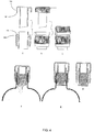
FIG. 4A is an exploded cutaway view of a fourth embodiment of the cap of the present writing that does not form part of the invention, depicting the two pieces of the cap. -
FIG. 4B is an exploded outside perspective of a fourth embodiment of the cap of the present writing that does not form part of the invention, depicting the two pieces of the cap. -
FIG. 4C is an outside perspective of a fourth embodiment of the cap of the present writing that does not form part of the invention, depicting the two pieces of the cap coupled together prior to engaging the mechanism to release the beverage additives into the fluid. -
FIG. 4D is a cutaway closed perspective of a fourth embodiment of the cap of the present writing that does not form part of the invention, depicting the two pieces of the cap coupled together and filled with beverage additives prior to engaging the mechanism to release the beverage additives into a fluid. -
FIG. 4E is a cutaway view of a fourth embodiment of the cap of the present writing that does not form part of the invention, depicting the two pieces of the cap coupled together, filled with beverage additives, and placed atop a bottle prior to engaging the mechanism to release the beverage additives into a fluid. -
FIG. 4F is a cutaway view of a fourth embodiment of the cap of the present writing that does not form part of the invention, depicting the two pieces of the cap coupled together, filled with beverage additives, placed atop a bottle, and engaged to break all seals and release the beverage additives into the bottle. - Unless defined otherwise, all technical and scientific terms used herein have the same meaning as commonly understood by one of ordinary skill in the art to which this writing belongs. Generally, the nomenclature used herein and the manufacturing procedures for the devices and components described below are well known and commonly employed in the art. Conventional methods are used for these procedures, such as those provided in the art and various general references. Where a term is provided in the singular, the inventor also contemplates the plural of that term. The terms top, bottom, lower, upper, up, down, into, out of, upwards, downwards, and other directional terms are not limiting and are used merely as points of reference, and as is clear in the disclosure and embodiments of the writing, alternative arrangements, alignments, and points of reference may be used. As employed throughout the disclosure, the following terms, unless otherwise indicated, shall be understood to have the following meanings (although obvious modifications are contemplated):
- "Beverage additives" means vitamins, minerals, supplements, medications, medicines, drugs, amino acids, electrolytes, enzymes, nutrients, fiber, antioxidants, protein, food, vegetables, fruits, berries, plants, flowers, algae, nuts, herbs, teas, seeds, barks, roots,
juices, leaves, trees, grasses, flavorings, sweeteners, beverage concentrates, chemical additives, coffee, caffeine, alcohol, all in powdered, fluid, or solid state; - "Bottle" means a portable container for holding fluids and liquids, characteristically having a neck and mouth and made of generally impermeable material such as but not limited to glass or plastic;
- "Cap" means a protective cover or seal, especially one that closes off an end, opening or a tip of a bottle;
- "Compartment" means a partitioned section or chamber within a larger enclosed area; "Fluid" means any liquid or fluid substance, whether or not capable of consumption or ingestion by a human, including but not limited to water, juice, drinks, beverages, teas, chemicals, and solvents;
- "Reservoir" means a receptacle or chamber for storing fluids, solids, or powders, comprising one or more separate receptacles or chambers for storing and keeping separate a plurality of fluids, solids, or powders; and
- "Seal" means a device or mechanism attached to or comprising an object, which must be broken when the object is opened, insuring that the contents have not been tampered with or altered;
- Other technical terms used herein have their ordinary meaning in the art in which they are used, as exemplified by a variety of technical dictionaries.
- The present writing discloses a sealed reservoir cap or safety sealed reservoir compartment bottle cap. The sealed reservoir cap is preferably comprised of two pieces (first and second hollow parts, also referred to as top piece and bottom piece) which interlockingly fit together. The second hollow part (bottom piece) comprises a chamber for receiving the first hollow part (top piece), a punchable seal (bottom seal), an annular part (surface) for securing to a bottleneck of a screw top container, a screw top seal, and an annular seal (lock seal). The first hollow part (top piece) comprises a reservoir for receiving and storing beverage additives. The reservoir in the top piece is of a shape which allows the reservoir to function as a piercing element for breaking seals. Both hollow parts (pieces) are preferably comprised of an opaque material which blocks all light from spoiling the beverage additives. When the two hollow parts (pieces) are fitted together, multiple seals prevent spoilage of the beverage additives due to heat, humidity, air, and other environmental factors. The seals further prevent the fluid in the bottle from prematurely mixing with the beverage additives. Both hollow parts (pieces) are preferably fabricated from a material such as plastic through an injection mold or similar process. One skilled in the art, however, will recognized that other materials, including but not limited to polymer resin, paper, glass, rubber, silica, carbon, metal, or a combination of these materials (including plastic), may be utilized to achieve the benefits of the writing.
- A first embodiment of the second hollow part (bottom piece) 5 is depicted in
FIG. 1 . The second hollow part (bottom piece) 5 as represented inFIG. 1A represents a cutaway view of the second hollow part (bottom piece) 5, andFIG. 1B depicts the exterior view of the second hollow part (bottom piece) 5. Second hollow part (bottom piece) 5 is comprised of ahollow compartment 10, formed byinterior wall 58. which has acompartment opening 15 at the top to receive the first hollow part (top piece) 70, and comprises a plurality of second protrusions (rings) 30 of a preferably triangular form which preventbeverage additives 170 and bottle fluid 180 from traveling up through the first annular space (gap) 65 between the first hollow part (top piece) 70 and second hollow part (bottom piece) 5 when fitted together. The second protrusions (rings) 30 are towards the bottom ofcompartment 10 along second hollow part (bottom piece)interior wall 58, and are spaced in a manner as to maximize control, minimize additional raw materials for manufacture, maximize sealing of the cap 1, and minimize the effort required to move the piercingmechanism 75 which is in contact with the second protrusions (rings) 30. - At the bottom 20 of
compartment 10 is apunchable seal 25 which prevents premature exposure of thebeverage additives 170, and ensures that thebeverage additive 170 and the fluid 180 in thebottle 160 are not tampered with or otherwise contaminated. Said punchable seal (bottom seal) 25 is similar to those well known in the art and used on plastic spouts of half gallon cartons containing milk and juice. Thepunchable seal 25 is of a particular thickness necessary to prevent accidental discharge of the beverage additives, considering changes in temperature, pressure, humidity, and other environmental fluctuations to be encountered. Said punchable seal (bottom seal) 25 is of a lesser thickness around the periphery, creating line ofweakness 28, which enablespunchable seal 25 to remain sealed until pushed upon by another component of the sealed reservoir cap (bottle cap) 1. The force necessary to break thepunchable seal 25, and thus combine thebeverage additives 170 with thebottled fluid 180, can vary depending upon the intended use of thebeverage additives 170 and the bottled fluid 180 (e.g. stronger seal for travel, lighter seal for children or the elderly). Furthermore, the force necessary to break thepunchable seal 25 can be varied depending upon the type of piercingmechanism 75 embodied in the present writing (e.g., screw mechanism or plunger mechanism). - Second hollow part (bottom piece) 5 further comprises annular part (exterior wall) 48, which with rings or
threads 35, enables sealed reservoir can (bottle cap) 1 to screw ontobottle 160. Such screw cap mechanisms as rings orthreads 35 are well known in the art. At or near the base of annular part (exterior wall) 48, line ofweakness 45 separates annular part (exterior wall) 48 fromscrew cap seal 40. When sealed reservoir cap (bottle cap) 1 is twisted for removal frombottle 160, line ofweakness 45 breaks, separatingscrew cap seal 40 from sealed reservoir cap (bottle cap) 1 along line ofweakness 45. Line ofweakness 45 is of a particular strength to ensure that insignificant twisting can occur due to handling, bottling, transport, etc. without breaking line of weakness 45 - however sealed reservoir cap (bottle cap) 1 cannot be removed without breaking line ofweakness 45. Line ofweakness 45 andscrew cap seal 40 further ensure that thebeverage additives 170 andfluid 180 are fresh, and have not been prematurely released, exposed, contaminated or otherwise adulterated. - At or near compartment opening 15 of second hollow part (bottom piece) 5 is located
barrier surface 60 which stops the downward motion of first hollow part (top piece) 70 when depressed to releasebeverage additives 170 intobottle 160. Adjacent tobarrier surface 60 is notchedgroove 50. Notchedgroove 50 is a recessed area which is of sufficient size to receivering 90 to lock first hollow part (top piece) 70 into second hollow part (bottom piece) 5. Notchedgroove 50 andring 90 can preferably be generally triangular in shape; however squared, rounded, or otherwise shaped grooves and rings are anticipated by the inventor. - At the top of second hollow part (bottom piece) 5 is removable annular seal (lock seal) 55. Removable annular seal (lock seal) 55 prevents first hollow part (top piece) 70 from being prematurely depressed into second hollow part (bottom piece) 5. When removable annular seal (lock seal) 55 is removed (such as a via a break away pull tab handle as illustrated in
FIG. 1 ), first hollow part (top piece) 70 is free to be pressed downwards into second hollow part (bottom piece) 5. As shown inFIG. 1D , removable annular seal (lock seal) 55 is of a precise height. When removable annular seal (lock seal) 55 is removed, this height is removed, first hollow part (top part) 70 is then free to travel downward the distance represented by the now removed removable annular seal (lock seal) 55. This distance (along with the angle of inclination of angled circular edge 100) is exactly or reasonably approximate the distance necessary for first hollow part (top piece) 70 to come to rest onbarrier surface 60, withring 90 locking into notchedgroove 50. This distance is further exactly or reasonably approximately sufficient to allow piercingmechanism 75 to partially (but not wholly) break open punchable seal (bottom seal) 25 at line ofweakness 28. This distance represented by the height of removable annular seal (lock seal) 55 allows piercingmechanism 75 to break open punchable seal (bottom seal) 25, but not fully sever or break through all of line ofweakness 28. With part of line ofweakness 28 remaining unbroken, punchable seal (bottom seal) 25 is partially attached to second hollow part (bottom piece) 5, and thus moves sufficiently to allow all of thebeverage additives 170 to be released intobottle 160 without punchable seal (bottom seal) 25 falling intobottle 160, causing a choking or other safety hazard. - A first embodiment of first hollow part (top piece) 70 of sealed reservoir cap (bottle cap) 1 is disclosed in
FIG. 1 . First hollow part (top piece) 70 as represented inFIG. 1 represents a cutaway view of the first hollow part (top piece) 70, andFIG. 1B depicts the exterior view of the first hollow part (top piece) 70. First hollow part (top piece) 70 comprises ahollow piercing mechanism 75, which is formed byexterior wall 80, and has an angledcircular edge 100 at the bottom of piercingmechanism 75. Angledcircular edge 100 is at an angle of inclination necessary, when punchable seal (lock seal) 55 is removed and first hollow part (top piece) 70 is pushed into second hollow part (bottom piece) 5, that angledcircular edge 100 breaks through most, but not all, of line ofweakness 28 to open punchable seal (bottom seal) 25. This allows punchable seal (bottom seal) 25 to be partially attached at line ofweakness 28 to second hollow part (bottom piece) 5 so that punchable seal (bottom seal) 25 does not fall intofluid 180 inbottle 160, creating a choking or other safety hazard. - First hollow part (top piece) 70 further comprises first protrusion (barrier surface) 85, which when first hollow part (top piece) 70 is depressed, comes to rest on
barrier surface 60. This is one component which stops first hollow part (top piece) 70 from being pushed too far into second hollow part (bottom piece) 5, thus causing punchable seal (bottom seal) 25 to fall intobottle 160. Near or adjacent to first protrusion (barrier surface) 85 isring 90 which locks into notchedgroove 50 as disclosed above. First hollow part (top piece) 70 further comprisescap top 95, which is of sufficient thickness and strength to prevent tampering or other adulteration ofbeverage additives 170. -
FIG. 1C shows an exterior view of first hollow part (top piece) 70, which has been filled with beverage additive 170 (not shown), and coupled with second hollow part (bottom piece) 5. Removable annular seal (lock seal) 55 prevents premature depression of first hollow part (top piece) 70 into second hollow part (bottom piece) 5.Cap top 95 may include grooves (or other textured surface) as depicted inFIG. 1C to facilitate handling by an individual. -
FIG. 1D shows a cutaway view of sealed reservoir cap (bottle cap) 1, where first hollow part (top piece) 70 has been filled withbeverage additive 170, and coupled with second hollow part (bottom piece) 5. This cutaway view further demonstrates that removable annular seal (lock seal) 55 is of such a size to govern the distance needed to be traveled by first hollow part (top piece) 70 when depressed into second hollow part (bottom piece) 5.FIG. 1D further illustrates the first annular space (gap) 65 which is between first hollow part (top piece) 70 and second hollow part (bottom piece) 5 when coupled. This allows the unencumbered movement of first hollow part (top piece) 70 when pressed downward into second hollow part (bottom piece) 5.FIG. 1D further shows second protrusions (rings) 30, which are of a generally triangular profile, which serve to prevent fluid inbottle 160 from moving up through first annular space (gap) 65 when punchable seal (bottom seal) 25 is broken. This will prevent fluid from leaking out of the cap once first hollow part (top piece) 70 has been depressed into second hollow part (bottom piece) 5, and further prevents leakage whenbottle 160 is preferably shaken to mixbeverage additives 170 withfluid 180. Second protrusions (rings) 30 further keepbeverage additives 170 sealed and protected from exposure. -
FIG. 1E shows entire sealed reservoir cap (bottle cap) 1, comprising second hollow part (bottom piece) 5, first hollow part (top piece) 70, andbeverage additive 170, which has been screwed on to bottle 160.Beverage additive 170 is sealed within sealed reservoir cap (bottle cap) 1, and sealed reservoir cap (bottle cap) 1 is placed onbottle 160 immediately after filling, sterilization, and/or pasteurization offluid 180 inbottle 160. Placement of sealed reservoir cap (bottle cap) 1 onbottle 160 during production ensures that the contents of sealed reservoir cap (bottle cap) 1 and bottle 160 are as clean and sterile as possible.FIG. 1E demonstrates sealed reservoir cap (bottle cap) 1 prior to the removal of removable annular seal (lock seal) 55. -
FIG. 1F shows sealed reservoir cap (bottle cap) 1 after removable annular seal (lock seal) 55 is removed, and first hollow part (top piece) 70 is pushed down into second hollow part (bottom piece) 5, which causes angledcircular edge 100 to push into punchable seal (bottom seal) 25, which partially detaches along line ofweakness 28, causing beverage additive 170 (stored incompartment 10 and the hollow center of piercing mechanism 75) to empty intobottle 160 and mix with fluid 180 (not featured). -
FIG. 2 demonstrates a second alternative embodiment of sealed reservoir cap (bottle cap) 1 that does not form part of the invention. As is clear by comparingFIGS. 1 and2 , almost all parts of sealed reservoir can (bottle cap) 1 are the same in each embodiment, except for the components identified inFIG. 2 . As depicted in the cutaway view ofFIG. 2A ,exterior surface 105 ofcap top 95 of first hollow part (top piece) 70 is of a different form than in the first embodiment. This allows for the formation ofnotch 110, which fits interlockingly withgroove 113 of second hollow part (bottom piece) 5. When first hollow part (top piece) 70 is depressed or pushed down into second hollow part (bottom piece) 5, the lateral movement of first hollow part (top cap) 70 is stopped by the locking ofnotch 110 withgroove 113. This alternative method of locking allows for a different sealed reservoir cap (bottle cap) 1 design which may utilize less raw materials for production, and which may be easier to engage for different individuals. This alternative embodiment further reduces the weight of sealed reservoir cap (bottle cap) 1, thereby reducing shipping costs. The alternative embodiment further provides a larger grooved gripping surface forexterior surface 105, which may be easier for use by weaker individuals such as children or the elderly.FIG. 2B shows the same components asFIG. 2A from an exterior view.FIG. 2C shows an exterior view of first hollow part (top piece) 70 coupled with second hollow part (bottom piece) 5 prior to removal of removable annular seal (lock seal) 55.FIG. 2D shows a cutaway view of sealed reservoir cap (bottle cap) 1, where removable annular seal (lock seal) 55 has been removed, first hollow part (top piece) 70 has been pushed into second hollow part (bottom piece) 5, and notch 110 has engaged withgroove 113, locking first hollow part (top piece) 70 with second hollow part (bottom piece) 5. Partially attached punchable seal (bottom seal) 25 is not shown. -
FIG. 3 demonstrates a third alternative embodiment of sealed reservoir cap (bottle cap) 1 that does not form part of the invention. As is clear by comparingFIGS. 1 and3 , almost all parts of sealed reservoir cap (bottle cap) 1 are the same in each embodiment, except for the components identified inFIG. 3 . This alternative embodiment of sealed reservoir can (bottle cap) 1 discloses a screw method for moving first hollow part (top piece) 70 into second hollow part (bottom piece) 5 and breaking punchable seal (bottom seal) 25. This further protects against accidental engagement of first hollow part (top piece) 70, preventing premature discharge ofbeverage additive 170 intobottle 160. This alternative embodiment further facilitates use by individuals for which it may be difficult to press down first hollow part (top piece) 70 into second hollow part (bottom piece) 5 with sufficient force to partially detach punchable seal (bottom seal) 25 at line ofweakness 28, as demonstrated by the other embodiments of sealed reservoir cap (bottle cap) 1. As depicted in the cutaway view ofFIG. 3A , the screw mechanism is achieved with an alternative capexterior surface 115 of first hollow part (top piece) 70, which comprisesconcentric rings 120, andtwist lock 123. Second hollow part (bottom piece) 5 has extendedtop wall 125, which makes second hollow part (bottom piece) 5 larger than the other embodiments of the writing. This extendedtop wall 125 comprisesconcentric ring 130, which starts at or near the base oftop wall 125, and forms the guide ring of the screw
mechanism. As depicted inFIG. 3B ,concentric ring 130 wraps around the exterior edge of extendedtop wall 125 in an angled manner. Not shown is the reverse ofFIG. 3B , which would fully demonstrate thatconcentric ring 130 forms one continuous unitary ring. - Extended
top wall 125 further comprises a plurality oftwist lock teeth 135.Twist lock teeth 135 are preferably formed so that one side is slightly angled, and the other side is at or near perpendicular across an axis. The twist lock teeth may be all the same height, or may be of different height to achieve the desired results, and further may have differing angles to accomplish the same results. The desired goal oftwist lock 123 and twist lockteeth 135 is that twist lockteeth 135 are angled to allowtwist lock 123 to pass over the angled surface of twist lockteeth 135 in one direction, but prevent the twist lockteeth 135 from moving in the opposite direction.Twist lock teeth 135 may be angled in such a manner as to facilitate clockwise or counterclockwise rotation of first hollow part (top piece) 70, depending upon the needs of the product, the manufacturer, the producer, the target market, etc. Once removable annular seal (lock seal) 55 is removed, first hollow part (top piece) 70 is twisted, andtwist lock 123 passes over some twist lockteeth 135, first hollow part (top piece) 70 cannot be twisted to its original position. This further ensures that the sealed reservoir cap (bottle cap) mechanism 1 is engaged only once, and prevents tampering with the beverage additives or fluid contained in the bottle. The individual continues to twist first hollow part (top piece) 70, using the grooved or otherwise textured surface of top pieceexterior surface 115 to facilitate gripping and twisting of the bottle cap. -
FIG. 3B shows an exterior perspective of the pieces as depicted inFIG. 3A. FIG. 3C shows sealed reservoir cap (bottle cap) 1, with beverage additives 170 (not shown) stored in first hollow part (top piece) 70 and second hollow part (bottom piece) 5, prior to the removal of removable annular seal (lock seal) 55.FIG. 3D shows sealed reservoir cap (bottle cap) 1 with removable annular seal (lock seal) 55 removed, and after an individual has twisted first hollow part (top piece) 70 in a manner sufficient to push first hollow part (top piece) 70 down, causing piercingmechanism 75 to partially detach punchable seal (bottom seal) 25 at line ofweakness 28 andrelease beverage additive 170 intobottle 160.FIG. 3E shows a cutaway view ofFIG. 3D, and FIG. 3F shows a cutaway view ofFIG. 3C . Punchable seal (bottom seal) 25 is not shown inFIGS. 3D, 3E, or 3F . -
FIG. 4 demonstrates a fourth alternative embodiment of sealed reservoir cap (bottle cap) 1 that does not form part of the invention. As is clear by comparingFIGS. 1 and4 , almost all parts of sealed reservoir cap (bottle cap) 1 are the same in each embodiment,
except for the components identified inFIG. 4 . As depicted in the cutaway view ofFIG. 4A , exterior surface 140 ofcap top 95 of first hollow part (top piece) 70 is of a different form than in the first embodiment. This allows for the formation ofring 145, which fits interlockingly withring 150 and recessedgroove 155 of second hollow part (bottom piece) 5. When first hollow part (top piece) 70 is depressed or pushed down into second hollow part (bottom piece) 5, the lateral movement oftop cap 70 is stopped by the locking ofring 145 withring 150 andgroove 155. This alternative method of locking allows for a different sealed reservoir cap (bottle cap) 1 design which may utilize less raw materials for production, and which may be easier to engage for different individuals. This alternative embodiment further reduces the weight of sealed reservoir cap (bottle cap) 1, thereby reducing shipping costs. The alternative embodiment further provides a larger grooved (or otherwise textured) gripping surface for exterior surface 140, which may be easier for use by weaker individuals such as children or the elderly.FIG. 4B shows the same components asFIG. 4A from an exterior view.FIG. 4C shows an exterior view of first hollow part (top piece) 70 coupled with second hollow part (bottom piece) 5 prior to removal of removable annular seal (lock seal) 55.FIG. 4D shows a cutaway view of the exterior view inFIG. 4C -
FIG. 4E shows entire sealed reservoir cap (bottle cap) 1, comprising first hollow part (bottom piece) 5, second hollow part (top piece) 70, andbeverage additive 170, which has been screwed on to bottle 160.Beverage additive 160 is sealed within sealed reservoir cap (bottle cap) 1, and sealed reservoir cap (bottle cap) 1 is placed onbottle 160 immediately after filling, sterilization, and/or pasteurization offluid 180 inbottle 160. Placement of sealed reservoir cap (bottle cap) 1 onbottle 160 during production ensures that the contents of sealed reservoir cap (bottle cap) 1 and bottle 160 are as clean and sterile as possible.FIG. 4E demonstrates sealed reservoir cap (bottle cap) 1 prior to the removal of removable annular seal (lock seal) 55. -
FIG. 4F shows sealed reservoir cap (bottle cap) 1 after removable annular seal (lock seal) 55 is removed, and first hollow part (top piece) 70 is pushed down into second hollow part (bottom piece) 5, which causes angledcircular edge 100 to push into punchable seal (bottom seal) 25, which partially detaches along line ofweakness 28, causing beverage additive 170 (stored incompartment 10 and the hollow center of piercing mechanism 75) to empty intobottle 160 and mix with fluid 180 (not featured).FIG. 4F further demonstrates howring 145 has engaged withring 150 and recessedgroove 155, lockingtop piece 70 with second hollow part (bottom piece) 5. - These aspects of the writing, as well as others described herein, can be achieved by using the methods, articles of manufacture and compositions of matter described herein. To gain a full appreciation of the scope of the present writing, it will be further recognized that various aspects of the present writing can be combined to make desirable embodiments of the writing.
- The following are non-limiting examples of the present writing. A bottled water producer desires to add beverage additives, including flavoring, fruit concentrates, sweeteners, vitamins, minerals, and herbal supplements to water. The producer does not desire to mix the beverage additives with the water when the bottled water is produced, because the flavors of the beverage additives, when combined with water, may change taste during prolonged exposure to a plastic bottle. Furthermore, the water and flavored drink mix (including any sweetening agents) may degrade the vitamins and herbal supplements (and in some cases such as vitamin C, rapidly degrade). The bottled water producer would thus be required to add additional vitamins and herbal supplements to the beverage when produced, increasing costs. After a determined period of time (the expiration date) less than the labeled amounts of vitamins and herbal supplements will be present in the beverage, thus shortening the shelf life of the beverage.
- Using the sealed reservoir cap of the present writing, the bottled water producer can store the beverage additives in the reservoir of the bottle cap. The components are kept dry and sealed, away from heat, light, air, humidity, and other environmental concerns which might degrade the quality and strength of the components of the beverage additives. Beverage additives retain their quality and strength for a significantly longer period of time when maintained in a dry, cool, sealed, low humidity, and dark environment such as the one created by the present writing.
- Further with the present writing, the bottled water producer can sterilize, filter, and pasteurize the water in the bottle. Doing so when the beverage additives are present can degrade the strength, quality, and efficacy of the drink mix, vitamins, and herbal supplements and other beverage additives. The present writing allows the bottled water producer to maximize the safety of the water separately from maximizing the safety of the dry components.
- Using an assembly line system or similar machinary in a sterile (or otherwise protected and safe) environment, the top piece of the cap of the writing is filled with a predetermined amount of a plurality of beverage additives which are to be added to water. Once the beverage additives are added to the top piece, the bottom piece is joined with the top piece. All seals remain in place, protecting the beverage additives, and ensuring that the beverage additives are not prematurely released into the environment or the bottle.
- Concurrently water is placed into a sterile bottle through an assembly line or similar processing machine. The water is filtered, heated, and otherwise cleaned to the highest of purity standards.
- The entire sealed reservoir cap is then screwed on the water bottle. This is done in a manner as to ensure a tight (and thus safe) seal, but not too strong as to break any of the safety seals. The water bottle with attached sealed reservoir cap is then checked for safety and other factors, and then packaged for shipping.
- Upon purchase of the bottle with attached sealed reservoir cap, the consumer can quickly determine that all of the safety seals are still intact. If intact, the consumer removes the removable annular seal (lock seal), and depresses the first hollow part (top piece) of the sealed reservoir cap into the second hollow part (bottom piece) of the sealed reservoir cap through either pushing, or in an alternative embodiment, by screwing. As the first hollow part (top piece) of the sealed reservoir cap moves down, the piercing mechanism partially breaks the punchable seal (bottom seal) along its line of weakness. This allows the dried beverage additives to empty down into the water in the bottle below. The punchable seal (bottom safety seal) remains attached at some part of the line of weakness as to prevent a choking or other safety hazard. The consumer stops moving the first hollow part (top piece) when it clicks or locks into place with the second hollow part (bottom piece). The consumer shakes or otherwise agitates the contents of the bottle to mix the beverage additives with the water. When done mixing the contents, the consumer unscrews the entire sealed reservoir cap (bottle cap) (which is now the first hollow part (top piece) and the second hollow part (bottom piece) locked together), and enjoys the mixed beverage.
- In a further example of the sealed reservoir cap of the present writing, the sealed reservoir cap (bottle cap) reservoir is divided into separate chambers which can store and keep separate dried beverage additives. The sealed reservoir cap (bottle cap) can further be used to store liquid beverage additives, as well as both liquid and dry beverage additives concurrently.
- In a further example of the sealed reservoir cap of the present writing, the beverage is a juice or a tea.
- In a further example of the sealed reservoir cap of the present writing, the entire sealed reservoir cap (bottle cap) is removed prior to depressing the top piece, and the contents of the bottle are heated on a stove, microwave, or other heating device. The sealed reservoir cap (bottle cap) is then reattached, the first hollow part (top piece) is pushed down into the second hollow part (bottom piece), and the beverage additives are added to warm or hot water as needed for the intended beverage.
- In a further example of the sealed reservoir cap of the present writing, the sealed reservoir cap is comprised of a material to protect as much as possible the contents stored therein from oxidation, moisture light, air, heat and other elements which might degrade the quality and strength of the materials stored therein.
Claims (15)
- A sealed reservoir cap (1) for attaching to a bottle (160) comprising:a first hollow part (70) capped at one end thereof;a second hollow part (5) having a seal (25) closing one end thereof and slidably receiving the first hollow part (70) therein with the punchable seal (25) axially opposite from the capped end to define an enclosed reservoir therebetween, and having a barrier surface (60) at or near a compartment opening (15) of the second hollow part (5);an annular part (48) disposed around the outside of the second hollow part (5) to define a second annular space between the annular part (48) and the second hollow part (5), the annular part (48) formed with threads extending around its inner diameter to threadably engage the bottleneck of the bottle (160) in the second annular space and dispose the punchable seal (25) within the bottle (160);characterized in that the first hollow part (70) is formed with a first protrusion (85) on its outer diameter and a first recess, wherein said first hollow part (70) includes a ring (90) near or adjacent to the first protrusion (85); and the second hollow part (5) further comprising:a second protrusion (30) around an inner diameter and a second recess to receive the first protrusion (85) therein, the first (70) and second (5) hollow parts defining a first annular space (65) therebetween sealed by engagement of the second protrusion against the first recess on the outer diameter of the first hollow part (70); anda notched groove (50), wherein the notched groove (50) is adjacent to the barrier surface (60) and is arranged to receive said ring (90).
- The sealed reservoir cap (1) of claim 1, wherein the punchable seal (25) has a scored line of weakness (28) such that the uncapped end dislodges a portion of the punchable seal (25).
- The sealed reservoir cap (1) of claim 1, wherein the uncapped edge is defined by an oval.
- The sealed reservoir cap (1) of claim 1 fabricated from materials selected to prevent degradation of contents within the enclosed reservoir.
- The sealed reservoir cap (1) of claim 1, wherein the enclosed reservoir contains dry or liquid contents.
- The sealed reservoir cap (1) of claim 5, wherein the contents of the enclosed reservoir are released upon dislodging the punchable seal (25).
- The sealed reservoir cap (1) of claim 1, wherein the first and second hollow parts (70, 5) and the annular part (48) are one continuous piece of material.
- The sealed reservoir cap (1) of claim 1, wherein the wherein the first and second hollow parts (70, 5) and the annular part (48) are more than one piece of material.
- The sealed reservoir cap (1) of claim 1, wherein more than one enclosed reservoir lies within the first and second hollow parts (70, 5).
- The sealed reservoir cap (1) of claim 1, further comprising a removable annular seal (55) holding the two hollow parts (70, 5) in an axially fixed, spaced apart relationship and, upon removal of the removable annular seal (55), allowing the first hollow part (70) to be pushed into the second hollow part (5) for the first protrusion (85) to be received in the second recess and the uncapped end of the first hollow part (70) to dislodge the punchable seal (25).
- A method for forming the sealed reservoir cap (1) of claim 1, the method comprising the steps of:forming a first hollow part (70) capped at one end thereof;forming a second hollow part (5) having a seal (25) closing one end thereof and capable of slidably receiving the first hollow part (70) therein with the seal (25) axially opposite from the capped end to define an enclosed reservoir therebetween;forming a first annular space (65) between the two hollow parts;forming a removable annular seal (55) disposed to hold the two hollow parts (70, 5) in an axially fixed spaced apart relationship;wherein the first hollow part (70) can be pushed into the second hollow part (5) for the first protrusion (85) to be received in the second recess and the uncapped end of the first annular part to dislodge the punchable seal (25) by removing the removable seal;forming an annular part (48) disposed around the outside of the second hollow part (5) to define a second annular space between the annular part and the outside of the second hollow part (5);forming threads extending around the inner diameter of the third annular part to engage a bottleneck in the second annular space and dispose the seal (25) within the bottle (160);characterized in that:the forming of the first hollow part (70) includes forming a first protrusion (85) on its outer diameter and a first recess, wherein said first protrusion (85) comprises a ring (90);forming a second protrusion (30) around the inner diameter of the second hollow part (5);forming a notched groove (50) arranged in said inner diameter to receive said ring (90); forming a second recess to receive the first protrusion (85) therein; andsealing said first annular space (65) by engagement of the second protrusion (30) with the first recess; wherein the seal is a punchable seal.
- The method of claim 11, further comprising the step of scoring a line of weakness (28) such that the uncapped end dislodges only a portion of the punchable seal (25).
- A bottle (160) comprising:the sealed reservoir cap (1) of any one of claims 1-10:a bottle (160) having an opening configured to be capped by the sealed reservoir cap (1); anda contents of the bottle;wherein the contents of the bottle (180) has been treated by one selected from the group of sterilizing, filtering, pasteurizing and combinations thereof prior to providing the sealed reservoir cap (1) to the bottle (160).
- A method of using the bottle (160) of claim 13, comprising emptying the contents of the sealed reservoir cap (1) and mixing the released reservoir contents with the contents of the bottle (180).
- A method of using the bottle (160) of claim 13, comprising the steps of removing the sealed reservoir cap (1) from the bottle (160) and heating the contents of the bottle (180) followed by emptying the contents of the sealed reservoir cap (1) into the bottle (160).
Applications Claiming Priority (3)
| Application Number | Priority Date | Filing Date | Title |
|---|---|---|---|
| US98258207P | 2007-10-25 | 2007-10-25 | |
| US99113707P | 2007-11-29 | 2007-11-29 | |
| PCT/US2008/080291 WO2009055311A1 (en) | 2007-10-25 | 2008-10-17 | Safety sealed reservoir cap |
Publications (3)
| Publication Number | Publication Date |
|---|---|
| EP2212216A1 EP2212216A1 (en) | 2010-08-04 |
| EP2212216A4 EP2212216A4 (en) | 2012-08-08 |
| EP2212216B1 true EP2212216B1 (en) | 2017-12-13 |
Family
ID=40296578
Family Applications (1)
| Application Number | Title | Priority Date | Filing Date |
|---|---|---|---|
| EP08841569.0A Not-in-force EP2212216B1 (en) | 2007-10-25 | 2008-10-17 | Safety sealed reservoir cap |
Country Status (15)
| Country | Link |
|---|---|
| US (1) | US9126731B2 (en) |
| EP (1) | EP2212216B1 (en) |
| JP (1) | JP2011500473A (en) |
| KR (2) | KR20100085040A (en) |
| AU (1) | AU2008317037B2 (en) |
| BR (1) | BRPI0818393A2 (en) |
| CA (1) | CA2702517C (en) |
| HK (1) | HK1117990A2 (en) |
| IL (1) | IL205060A0 (en) |
| MX (1) | MX2010004166A (en) |
| MY (1) | MY170589A (en) |
| RU (1) | RU2010120885A (en) |
| SG (1) | SG187489A1 (en) |
| WO (1) | WO2009055311A1 (en) |
| ZA (1) | ZA201002617B (en) |
Families Citing this family (47)
| Publication number | Priority date | Publication date | Assignee | Title |
|---|---|---|---|---|
| HK1117990A2 (en) * | 2007-10-25 | 2009-01-23 | Sunrider Corp | Safety sealed reservoir cap |
| ITMI20110054U1 (en) | 2011-02-16 | 2011-05-18 | Federico Thoman | BOTTLE WITH DISPENSER CAP |
| WO2012137091A1 (en) | 2011-04-05 | 2012-10-11 | Wyeth Llc | Cap with additive chamber and associated packaging unit |
| CA2835309A1 (en) * | 2011-05-16 | 2012-11-22 | Bottlecap Holdings Ltd. | Dispenser for dispensing material into a container |
| FR2975302B1 (en) | 2011-05-18 | 2013-05-10 | Fresenius Medical Care De Gmbh | CONNECTOR FOR DIALYSIS CONTAINER, CONTAINER HAVING SUCH CONNECTOR, METHOD FOR MANUFACTURING AND FILLING SUCH CONNECTORS AND CONTAINERS |
| PE20141796A1 (en) | 2011-06-14 | 2014-12-12 | Ax Lab Innovation Aps | CONTAINER SET AND ASSOCIATED METHOD |
| FR2978914B1 (en) * | 2011-08-11 | 2013-08-16 | Fresenius Medical Care De Gmbh | CONTAINER FOR DIALYSIS |
| GB2485254C (en) * | 2011-08-22 | 2013-12-25 | Eulysis Uk Ltd | A container having a recessed closure for drying and storing one or more active agents |
| WO2013033047A2 (en) * | 2011-09-02 | 2013-03-07 | The Sunrider Corporation Dba Sunrider International | Cap |
| US9138747B2 (en) | 2012-03-26 | 2015-09-22 | Alpha Tec Systems, Inc. | Specimen collection apparatus |
| US8640865B2 (en) | 2012-05-01 | 2014-02-04 | William Smart | Cap for storing materials separate from a body of liquid and facilitating subsequent mixing of the materials and the liquid |
| DE202012007857U1 (en) | 2012-08-09 | 2013-11-11 | Incap International Ltd. | Cap for a container |
| JP6064601B2 (en) * | 2013-01-09 | 2017-01-25 | オムロンヘルスケア株式会社 | Chemical tank and chemical pack for ultrasonic inhalers |
| US9604765B2 (en) * | 2013-03-14 | 2017-03-28 | Ahhmigo, Llc | Locking cap device and methods |
| CN103434745A (en) * | 2013-08-17 | 2013-12-11 | 珠海中富工业集团有限公司 | Bottle cap component and container bottle with same |
| KR101381356B1 (en) * | 2013-10-28 | 2014-04-04 | 주식회사 청아람 | Capsule cap for beverage containers |
| EP2886139A1 (en) * | 2013-12-20 | 2015-06-24 | Fresenius Medical Care Deutschland GmbH | Container |
| US9975684B1 (en) * | 2013-12-27 | 2018-05-22 | Mary Lisa Dvorak | Interactive dispensing bottle cap |
| KR101525862B1 (en) * | 2014-09-05 | 2015-06-03 | 최종서 | Chamber cap for vessel of cosmetics |
| FR3032433B1 (en) * | 2015-02-09 | 2017-02-10 | Rovipharm | DEVICE COMPRISING A FIRST COMPARTMENT TO BE MOUNTED ON A SECOND COMPARTMENT FOR MIXING THE CONTENT OF EACH COMPARTMENT |
| CN104787486A (en) * | 2015-03-08 | 2015-07-22 | 刘沛灵 | Water material separating, split charging and independent using mixing beverage bottle |
| US10479585B2 (en) | 2015-08-14 | 2019-11-19 | Yeti Coolers, Llc | Container with magnetic cap and container holder |
| US10093460B2 (en) | 2015-08-14 | 2018-10-09 | Yeti Coolers, Llc | Container with magnetic cap |
| USD787893S1 (en) | 2015-11-20 | 2017-05-30 | Yeti Coolers, Llc | Jug |
| JP6443322B2 (en) * | 2015-12-25 | 2018-12-26 | 株式会社デンソー | Ultrasonic sensor |
| US20180028406A1 (en) * | 2016-08-01 | 2018-02-01 | Jim Patton | Secure Controlled Substance Pill Dispensing Device |
| US11021314B2 (en) | 2016-10-17 | 2021-06-01 | Yeti Coolers, Llc | Container and method of forming a container |
| USD835937S1 (en) | 2016-10-17 | 2018-12-18 | Yeti Coolers, Llc | Container lid |
| US11034505B2 (en) | 2016-10-17 | 2021-06-15 | Yeti Coolers, Llc | Container and method of forming a container |
| US10959553B2 (en) | 2016-10-17 | 2021-03-30 | Yeti Coolers, Llc | Container and method of forming a container |
| US10959552B2 (en) | 2016-10-17 | 2021-03-30 | Yeti Coolers, Llc | Container and method of forming a container |
| WO2018089907A2 (en) * | 2016-11-11 | 2018-05-17 | Sc Shredder Ip, Llc | Automatic beverage mixer |
| USD860716S1 (en) | 2017-03-27 | 2019-09-24 | Yeti Coolers, Llc | Container lid |
| USD836388S1 (en) | 2017-03-27 | 2018-12-25 | Yeti Coolers, Llc | Container lid |
| USD836389S1 (en) | 2017-03-27 | 2018-12-25 | Yeti Coolers, Llc | Container lid |
| US11253431B2 (en) * | 2017-08-30 | 2022-02-22 | Viant Medical, LLC | Vial closure for rehydrating medication |
| UA127591C2 (en) * | 2018-05-25 | 2023-10-25 | Алістелла Са | Process for making a portable beverage product and a filling line therefore |
| USD896572S1 (en) | 2018-08-20 | 2020-09-22 | Yeti Coolers, Llc | Container lid |
| CN108910282B (en) * | 2018-09-10 | 2023-10-20 | 冯怀 | Beverage bottle with press puncture auto-lock mixed function |
| US11135131B2 (en) * | 2018-09-14 | 2021-10-05 | Board Of Trustees Of Michigan State University | Medication bottle with anti-tampering features |
| USD883737S1 (en) | 2018-10-17 | 2020-05-12 | Yeti Coolers, Llc | Lid |
| USD897151S1 (en) | 2018-10-17 | 2020-09-29 | Yeti Coolers, Llc | Lid |
| USD883738S1 (en) | 2018-10-17 | 2020-05-12 | Yeti Coolers, Llc | Lid |
| WO2020089294A1 (en) * | 2018-10-31 | 2020-05-07 | Montfort Solutions Gmbh | Capsule having a sealing foil having a predetermined breaking point |
| US11912480B2 (en) * | 2018-12-12 | 2024-02-27 | Katie Grobman | Container cap for controlled mixing and dispensing |
| US20210380313A1 (en) * | 2019-08-04 | 2021-12-09 | Yaakov Eliahu | Liquid dispenser |
| CN112849733A (en) * | 2021-02-09 | 2021-05-28 | 林丹宜 | Separating bottle cap and beverage bottle |
Citations (1)
| Publication number | Priority date | Publication date | Assignee | Title |
|---|---|---|---|---|
| JP2007076738A (en) * | 2005-09-15 | 2007-03-29 | Takeshige Yokota | Powder nutrient mixing container |
Family Cites Families (72)
| Publication number | Priority date | Publication date | Assignee | Title |
|---|---|---|---|---|
| US1059101A (en) | 1912-10-28 | 1913-04-15 | John S Alston | Closure for bottles. |
| US3603469A (en) * | 1968-04-11 | 1971-09-07 | Ambrogio Magni | Guarantee cap |
| US3802604A (en) * | 1972-02-28 | 1974-04-09 | Oreal | Device for storing two products separately and dispensing them simultaneously |
| IT994127B (en) * | 1973-08-03 | 1975-10-20 | Sigma Tau Ind Farmaceuti | DEVICE FOR THE HERMETIC CLOSING OF CONTAINERS EQUIPPED WITH PERFORATOR AND GOCCIMETER |
| IT1095010B (en) * | 1978-04-27 | 1985-08-10 | Sigma Tau Ind Farmaceuti | DEVICE SUITABLE FOR CONTAINING TWO PRODUCTS IN PARTICULAR MEDICINAL PRODUCTS, TO BE MIXED AT THE TIME OF USE |
| DE8502008U1 (en) | 1985-01-26 | 1985-08-29 | Celamerck Gmbh & Co Kg, 6507 Ingelheim | Closure cap for two-component packs |
| IT1185850B (en) * | 1985-08-02 | 1987-11-18 | Zambon Spa | DROP TANK CAP FOR BOTTLES |
| JPH0619502Y2 (en) * | 1988-02-22 | 1994-05-25 | 株式会社資生堂 | Container for mixing two types of storage |
| EP0338349B2 (en) * | 1988-04-18 | 1995-06-28 | Capsulit S.P.A. | Closure for monodose bottles and the like, comprising a reservoir provided with a breakable bottom |
| US5543097A (en) * | 1994-03-09 | 1996-08-06 | Fang; Ta-Yun | Methods for preparing polyacrylamide gels for electrophoretic analysis |
| ES2128220B1 (en) * | 1995-12-04 | 1999-12-16 | Cusi Lab | PHARMACEUTICAL CONTAINER OF TWO SEPARATE SUBSTANCES, WITH MIXING DEVICE, DOSAGE APPLICATION AND ITS ASSEMBLY PROCESS. |
| US6045254A (en) * | 1996-12-26 | 2000-04-04 | M.L.I.S. Projects Ltd. | Container having two or more compartments |
| IT1292677B1 (en) | 1997-02-28 | 1999-02-11 | Bormioli Metalplast Spa | PACKAGING TO KEEP THE PRODUCTS SEPARATE BEFORE USE. |
| US6786330B2 (en) * | 1997-10-14 | 2004-09-07 | Biogaia Ab | Two-compartment container |
| US5927549A (en) * | 1998-03-20 | 1999-07-27 | Aptargroup, Inc. | Dispensing structure with frangible membrane for separating two products |
| US6263923B1 (en) * | 1999-05-28 | 2001-07-24 | James A. Castillo | Device for maintaining separate ingredients in liquid food products |
| AU6066799A (en) | 1999-11-26 | 2001-05-31 | Lily Hsu | Container device for separately enclosing two different substances |
| AU2001260819A1 (en) | 2000-05-03 | 2001-11-12 | Amcad Holdings Limited | Multi-component mixing |
| IT1316941B1 (en) * | 2000-10-25 | 2003-05-13 | Lameplast Spa | BOTTLE FOR BICOMPENENT ESTEMPORARY PRODUCTS. |
| JP2002211622A (en) * | 2001-01-23 | 2002-07-31 | Mikuni Corp | Contents mixing cap |
| US6962149B2 (en) * | 2001-05-02 | 2005-11-08 | Expressasia.Com Snd. Bhd. | Insertable thermotic module for self-heating can |
| US6874648B2 (en) * | 2001-09-21 | 2005-04-05 | Owens-Illinois Closure Inc. | Closure with gas-barrier liner and package incorporating same |
| BR0105971A (en) | 2001-11-09 | 2003-08-05 | Gustavo Senna Chelles | Multicomponent Packaging |
| JP4048064B2 (en) * | 2002-02-28 | 2008-02-13 | 株式会社吉野工業所 | Two-component mixing dripping container |
| AU2002304300A1 (en) * | 2002-04-30 | 2003-11-17 | Bormioli Rocco And Figlio S.P.A. | Capsule containing a mixer substance for bottles containing pressurised liquids |
| US6976578B1 (en) * | 2002-05-07 | 2005-12-20 | Antony Austin Kenihan | Dispensing lid closure for beverage container and method of making and using the closure |
| WO2003095325A1 (en) * | 2002-05-10 | 2003-11-20 | Santen Pharmaceutical Co., Ltd. | Contamination preventive cap |
| US6840373B2 (en) * | 2002-05-16 | 2005-01-11 | Gregory A Gibler | Beverage storage and discharge cap assembly |
| JP2003335351A (en) | 2002-05-16 | 2003-11-25 | Hanshin Kasei Kogyo Kk | Container cap structure |
| KR101015747B1 (en) | 2002-06-20 | 2011-02-22 | 에스아이지 테크놀로지 리미티드 | Self-opening closure for composite packagings or for container or bottle nozzles for sealing with film material |
| JP2004075133A (en) * | 2002-08-20 | 2004-03-11 | Nippon Tansan Gas Co Ltd | Vessel sealing mechanism and cap used for the mechanism |
| US6705490B1 (en) * | 2002-09-12 | 2004-03-16 | Eric K. Lizerbram | Self contained additive reservoirs for use with beverage containers |
| JP2005022706A (en) * | 2003-07-03 | 2005-01-27 | Nippon Kouatsu Electric Co | Cap structure for drink container |
| US7221408B2 (en) | 2003-08-15 | 2007-05-22 | Samsung Electronics Co., Ltd. | Adaptive contrast enhancement method for video signals based on time-varying nonlinear transforms |
| EP1682443B1 (en) | 2003-10-27 | 2010-05-19 | Portola Packaging, Inc. | Twist-open closure having inclined frangible membrane |
| US7617929B2 (en) * | 2003-11-10 | 2009-11-17 | Lee Jeong-Min | Method and structure for mixing different materials in a pouch container |
| CA2544575C (en) * | 2003-11-10 | 2012-07-10 | Michael Edward Wood | Method and device for pressurizing containers |
| WO2005051775A2 (en) | 2003-11-28 | 2005-06-09 | Young-Kook Cho | Bottle |
| WO2005061340A1 (en) * | 2003-12-19 | 2005-07-07 | Dow Global Technologies Inc. | Lined container for curable liquid materials |
| JP2005247382A (en) * | 2004-03-05 | 2005-09-15 | Nippon Tansan Gas Co Ltd | Cap |
| US20050205438A1 (en) * | 2004-03-22 | 2005-09-22 | Valentin Hierzer | Container assembly for mixing substances |
| TWI344921B (en) | 2004-03-29 | 2011-07-11 | Masayuki Makita | Bottle cap |
| KR20050103807A (en) * | 2004-04-27 | 2005-11-01 | (주)일렉콤 | Double cap for adding addition in use |
| KR20050106690A (en) | 2004-05-06 | 2005-11-11 | 삼성전자주식회사 | Multi-domain liquid crystal display including the same |
| KR100599931B1 (en) * | 2004-05-07 | 2006-07-19 | (주)일렉콤 | Double cap for adding addition in use |
| KR20050109017A (en) | 2004-05-13 | 2005-11-17 | 한성원 | Material stored cap for container |
| KR20060011756A (en) * | 2004-07-31 | 2006-02-03 | 강석동 | Structure of cap for container |
| JP2006056593A (en) | 2004-08-18 | 2006-03-02 | Chouan Shoji Kk | Cap with storing room |
| KR20060028365A (en) * | 2004-09-24 | 2006-03-29 | 강석동 | Structure of cap for container |
| KR20060028356A (en) | 2004-09-25 | 2006-03-29 | 두우균 | The structure of coastal erosion prevention system constructed by the construction method of costal erosion prevention system & related method |
| JP4580726B2 (en) | 2004-10-08 | 2010-11-17 | 日本高圧電気株式会社 | Beverage container cap structure |
| US7703664B2 (en) * | 2004-10-15 | 2010-04-27 | Sonoco Development, Inc. | Paperboard container having curvilinear portion |
| JP2007276787A (en) | 2004-10-25 | 2007-10-25 | Coca Cola Co:The | Cap with storing chamber |
| KR100634354B1 (en) | 2004-11-23 | 2006-10-16 | 조영국 | Double cap for adding addition in use |
| KR100597217B1 (en) * | 2004-11-23 | 2006-07-06 | 조영국 | Double cap for adding addition in use |
| JP2006151457A (en) * | 2004-11-30 | 2006-06-15 | Yoshino Kogyosho Co Ltd | Cap |
| US7249690B2 (en) | 2004-12-24 | 2007-07-31 | Erie County Plastics Corporation | Independent off-bottle dispensing closure |
| ITMO20050057A1 (en) * | 2005-03-15 | 2006-09-16 | Lameplast Spa | PACKAGE FOR PRODUCTS WITH ESTEMPORANEA PREPARATION, PARTICULARLY MEDICINAL, PHARMACEUTICAL, COSMETIC OR SIMILAR. |
| US20080023349A1 (en) * | 2005-08-04 | 2008-01-31 | Balazik Ronald F | Internal Drink Mix System |
| US7614496B2 (en) | 2005-08-29 | 2009-11-10 | Steven Dvorak | Aqueous solution of an analgesic and a dispenser therefor |
| KR20070027903A (en) | 2005-08-30 | 2007-03-12 | 조영국 | Bottle cap with an additive and a straw |
| TWM289049U (en) | 2005-11-07 | 2006-04-01 | Shie Kuen Jan | Tea cover set for coldly making tea |
| JP2007269403A (en) | 2006-03-09 | 2007-10-18 | Tamaoka Sangyo Kk | Beverage container and cap for beverage container |
| US7951109B2 (en) * | 2006-09-22 | 2011-05-31 | Andeboh Holdings, Flp | Liquid chamber cap with compartment for use with injectables |
| US20080171109A1 (en) | 2007-01-16 | 2008-07-17 | Kun-Jhan Hsieh | Cap assembly for cold steeping drinks |
| EP2162363A4 (en) * | 2007-05-31 | 2010-09-01 | Joseph T Sorenson | Supplement compartment for beverage container |
| WO2009031167A1 (en) | 2007-09-04 | 2009-03-12 | Freeplast S.R.L. | A capsule for closing containers, comprising a reservoir for a mixable component |
| HK1117990A2 (en) | 2007-10-25 | 2009-01-23 | Sunrider Corp | Safety sealed reservoir cap |
| US20090308831A1 (en) | 2008-06-13 | 2009-12-17 | Anderson Michael R | Pouch carton and container fitments for use with any ingredients |
| US7874420B2 (en) * | 2009-02-09 | 2011-01-25 | Darren Coon | Affixable dispensing capsule |
| CN201587641U (en) | 2009-12-18 | 2010-09-22 | 景岳生物科技股份有限公司 | Bottle cap device |
| ITMI20110054U1 (en) * | 2011-02-16 | 2011-05-18 | Federico Thoman | BOTTLE WITH DISPENSER CAP |
-
2007
- 2007-12-04 HK HK07113250A patent/HK1117990A2/en not_active IP Right Cessation
-
2008
- 2008-10-17 BR BRPI0818393A patent/BRPI0818393A2/en not_active IP Right Cessation
- 2008-10-17 MX MX2010004166A patent/MX2010004166A/en unknown
- 2008-10-17 CA CA2702517A patent/CA2702517C/en active Active
- 2008-10-17 RU RU2010120885/12A patent/RU2010120885A/en not_active Application Discontinuation
- 2008-10-17 MY MYPI2010001666A patent/MY170589A/en unknown
- 2008-10-17 JP JP2010531142A patent/JP2011500473A/en active Pending
- 2008-10-17 SG SG2013003934A patent/SG187489A1/en unknown
- 2008-10-17 KR KR1020107008247A patent/KR20100085040A/en active Application Filing
- 2008-10-17 US US12/253,404 patent/US9126731B2/en active Active
- 2008-10-17 KR KR1020157016856A patent/KR20150083129A/en not_active Application Discontinuation
- 2008-10-17 WO PCT/US2008/080291 patent/WO2009055311A1/en active Application Filing
- 2008-10-17 EP EP08841569.0A patent/EP2212216B1/en not_active Not-in-force
- 2008-10-17 AU AU2008317037A patent/AU2008317037B2/en active Active
-
2010
- 2010-04-13 IL IL205060A patent/IL205060A0/en unknown
- 2010-04-14 ZA ZA2010/02617A patent/ZA201002617B/en unknown
Patent Citations (1)
| Publication number | Priority date | Publication date | Assignee | Title |
|---|---|---|---|---|
| JP2007076738A (en) * | 2005-09-15 | 2007-03-29 | Takeshige Yokota | Powder nutrient mixing container |
Also Published As
| Publication number | Publication date |
|---|---|
| EP2212216A4 (en) | 2012-08-08 |
| SG187489A1 (en) | 2013-02-28 |
| CA2702517A1 (en) | 2009-04-30 |
| KR20150083129A (en) | 2015-07-16 |
| IL205060A0 (en) | 2010-11-30 |
| MY170589A (en) | 2019-08-19 |
| ZA201002617B (en) | 2017-03-29 |
| US9126731B2 (en) | 2015-09-08 |
| AU2008317037A1 (en) | 2009-04-30 |
| BRPI0818393A2 (en) | 2017-05-16 |
| MX2010004166A (en) | 2010-06-25 |
| HK1117990A2 (en) | 2009-01-23 |
| CA2702517C (en) | 2016-09-06 |
| KR20100085040A (en) | 2010-07-28 |
| RU2010120885A (en) | 2011-11-27 |
| JP2011500473A (en) | 2011-01-06 |
| EP2212216A1 (en) | 2010-08-04 |
| AU2008317037B2 (en) | 2014-03-06 |
| WO2009055311A1 (en) | 2009-04-30 |
| US20090139951A1 (en) | 2009-06-04 |
Similar Documents
| Publication | Publication Date | Title |
|---|---|---|
| EP2212216B1 (en) | Safety sealed reservoir cap | |
| US6533113B2 (en) | System, devices and methods for storing and mixing substances | |
| US6527110B2 (en) | Device for storing and dispensing a substance by mating with a container and associated methods | |
| US20100044254A1 (en) | Beverage mix dispensing closure | |
| WO1999044901A1 (en) | A container | |
| KR20100131984A (en) | A closure with built-in storing compartment | |
| MX2010004472A (en) | Concentrate release cap. | |
| US20070141204A1 (en) | Beverage systems | |
| US20080105639A1 (en) | Fresh product dispensing system | |
| US11180296B2 (en) | Doser cap for liquid container | |
| US20120111744A1 (en) | Dispensing closure for container | |
| US20090120892A1 (en) | Bottle delivery system and methods thereof | |
| MXPA06008076A (en) | A capsule incorporating a doser and openable security cap, in particular for single-dose flagons. | |
| US9975684B1 (en) | Interactive dispensing bottle cap | |
| KR20130011553A (en) | Bottle cap for adding addition in use | |
| CN201436243U (en) | Storage room cover with safe seal | |
| WO2004113190A1 (en) | Bottle cap - container and dispenser of ingredients for quick drink preparation | |
| KR20090041265A (en) | A saparating instrument case of a solid body and a liquefied body | |
| RU121493U1 (en) | TWO-MONEY BEVERAGE BOTTLE | |
| US20240010401A1 (en) | Cap device for bottles | |
| US20040262175A1 (en) | Storage and dispensing device for mating with a liquid container to allow for mixing of a substance and the liquid | |
| WO2017126981A1 (en) | Closure for a container | |
| EP1716046B1 (en) | Container for liquid food products and procedure for packaging said liquid food products | |
| JP2005014919A (en) | Beverage vessel attached with separated raw material etc. | |
| WO2013128443A1 (en) | Single-use/disposable dosing capsule for containers |
Legal Events
| Date | Code | Title | Description |
|---|---|---|---|
| PUAI | Public reference made under article 153(3) epc to a published international application that has entered the european phase |
Free format text: ORIGINAL CODE: 0009012 |
|
| 17P | Request for examination filed |
Effective date: 20100520 |
|
| AK | Designated contracting states |
Kind code of ref document: A1 Designated state(s): AT BE BG CH CY CZ DE DK EE ES FI FR GB GR HR HU IE IS IT LI LT LU LV MC MT NL NO PL PT RO SE SI SK TR |
|
| AX | Request for extension of the european patent |
Extension state: AL BA MK RS |
|
| DAX | Request for extension of the european patent (deleted) | ||
| REG | Reference to a national code |
Ref country code: HK Ref legal event code: DE Ref document number: 1146660 Country of ref document: HK |
|
| A4 | Supplementary search report drawn up and despatched |
Effective date: 20120705 |
|
| RIC1 | Information provided on ipc code assigned before grant |
Ipc: B65D 51/28 20060101AFI20120629BHEP |
|
| 17Q | First examination report despatched |
Effective date: 20140327 |
|
| GRAP | Despatch of communication of intention to grant a patent |
Free format text: ORIGINAL CODE: EPIDOSNIGR1 |
|
| INTG | Intention to grant announced |
Effective date: 20170705 |
|
| GRAS | Grant fee paid |
Free format text: ORIGINAL CODE: EPIDOSNIGR3 |
|
| GRAA | (expected) grant |
Free format text: ORIGINAL CODE: 0009210 |
|
| AK | Designated contracting states |
Kind code of ref document: B1 Designated state(s): AT BE BG CH CY CZ DE DK EE ES FI FR GB GR HR HU IE IS IT LI LT LU LV MC MT NL NO PL PT RO SE SI SK TR |
|
| REG | Reference to a national code |
Ref country code: GB Ref legal event code: FG4D |
|
| REG | Reference to a national code |
Ref country code: AT Ref legal event code: REF Ref document number: 954130 Country of ref document: AT Kind code of ref document: T Effective date: 20171215 Ref country code: CH Ref legal event code: EP |
|
| REG | Reference to a national code |
Ref country code: IE Ref legal event code: FG4D |
|
| REG | Reference to a national code |
Ref country code: DE Ref legal event code: R096 Ref document number: 602008053371 Country of ref document: DE |
|
| REG | Reference to a national code |
Ref country code: NL Ref legal event code: MP Effective date: 20171213 |
|
| REG | Reference to a national code |
Ref country code: LT Ref legal event code: MG4D |
|
| PG25 | Lapsed in a contracting state [announced via postgrant information from national office to epo] |
Ref country code: SE Free format text: LAPSE BECAUSE OF FAILURE TO SUBMIT A TRANSLATION OF THE DESCRIPTION OR TO PAY THE FEE WITHIN THE PRESCRIBED TIME-LIMIT Effective date: 20171213 Ref country code: LT Free format text: LAPSE BECAUSE OF FAILURE TO SUBMIT A TRANSLATION OF THE DESCRIPTION OR TO PAY THE FEE WITHIN THE PRESCRIBED TIME-LIMIT Effective date: 20171213 Ref country code: FI Free format text: LAPSE BECAUSE OF FAILURE TO SUBMIT A TRANSLATION OF THE DESCRIPTION OR TO PAY THE FEE WITHIN THE PRESCRIBED TIME-LIMIT Effective date: 20171213 Ref country code: NO Free format text: LAPSE BECAUSE OF FAILURE TO SUBMIT A TRANSLATION OF THE DESCRIPTION OR TO PAY THE FEE WITHIN THE PRESCRIBED TIME-LIMIT Effective date: 20180313 |
|
| REG | Reference to a national code |
Ref country code: AT Ref legal event code: MK05 Ref document number: 954130 Country of ref document: AT Kind code of ref document: T Effective date: 20171213 |
|
| PG25 | Lapsed in a contracting state [announced via postgrant information from national office to epo] |
Ref country code: HR Free format text: LAPSE BECAUSE OF FAILURE TO SUBMIT A TRANSLATION OF THE DESCRIPTION OR TO PAY THE FEE WITHIN THE PRESCRIBED TIME-LIMIT Effective date: 20171213 Ref country code: LV Free format text: LAPSE BECAUSE OF FAILURE TO SUBMIT A TRANSLATION OF THE DESCRIPTION OR TO PAY THE FEE WITHIN THE PRESCRIBED TIME-LIMIT Effective date: 20171213 Ref country code: BG Free format text: LAPSE BECAUSE OF FAILURE TO SUBMIT A TRANSLATION OF THE DESCRIPTION OR TO PAY THE FEE WITHIN THE PRESCRIBED TIME-LIMIT Effective date: 20180313 Ref country code: GR Free format text: LAPSE BECAUSE OF FAILURE TO SUBMIT A TRANSLATION OF THE DESCRIPTION OR TO PAY THE FEE WITHIN THE PRESCRIBED TIME-LIMIT Effective date: 20180314 |
|
| PG25 | Lapsed in a contracting state [announced via postgrant information from national office to epo] |
Ref country code: NL Free format text: LAPSE BECAUSE OF FAILURE TO SUBMIT A TRANSLATION OF THE DESCRIPTION OR TO PAY THE FEE WITHIN THE PRESCRIBED TIME-LIMIT Effective date: 20171213 |
|
| PG25 | Lapsed in a contracting state [announced via postgrant information from national office to epo] |
Ref country code: CY Free format text: LAPSE BECAUSE OF FAILURE TO SUBMIT A TRANSLATION OF THE DESCRIPTION OR TO PAY THE FEE WITHIN THE PRESCRIBED TIME-LIMIT Effective date: 20171213 Ref country code: EE Free format text: LAPSE BECAUSE OF FAILURE TO SUBMIT A TRANSLATION OF THE DESCRIPTION OR TO PAY THE FEE WITHIN THE PRESCRIBED TIME-LIMIT Effective date: 20171213 Ref country code: SK Free format text: LAPSE BECAUSE OF FAILURE TO SUBMIT A TRANSLATION OF THE DESCRIPTION OR TO PAY THE FEE WITHIN THE PRESCRIBED TIME-LIMIT Effective date: 20171213 Ref country code: ES Free format text: LAPSE BECAUSE OF FAILURE TO SUBMIT A TRANSLATION OF THE DESCRIPTION OR TO PAY THE FEE WITHIN THE PRESCRIBED TIME-LIMIT Effective date: 20171213 Ref country code: CZ Free format text: LAPSE BECAUSE OF FAILURE TO SUBMIT A TRANSLATION OF THE DESCRIPTION OR TO PAY THE FEE WITHIN THE PRESCRIBED TIME-LIMIT Effective date: 20171213 |
|
| PG25 | Lapsed in a contracting state [announced via postgrant information from national office to epo] |
Ref country code: PL Free format text: LAPSE BECAUSE OF FAILURE TO SUBMIT A TRANSLATION OF THE DESCRIPTION OR TO PAY THE FEE WITHIN THE PRESCRIBED TIME-LIMIT Effective date: 20171213 Ref country code: AT Free format text: LAPSE BECAUSE OF FAILURE TO SUBMIT A TRANSLATION OF THE DESCRIPTION OR TO PAY THE FEE WITHIN THE PRESCRIBED TIME-LIMIT Effective date: 20171213 Ref country code: IT Free format text: LAPSE BECAUSE OF FAILURE TO SUBMIT A TRANSLATION OF THE DESCRIPTION OR TO PAY THE FEE WITHIN THE PRESCRIBED TIME-LIMIT Effective date: 20171213 Ref country code: IS Free format text: LAPSE BECAUSE OF FAILURE TO SUBMIT A TRANSLATION OF THE DESCRIPTION OR TO PAY THE FEE WITHIN THE PRESCRIBED TIME-LIMIT Effective date: 20180413 Ref country code: RO Free format text: LAPSE BECAUSE OF FAILURE TO SUBMIT A TRANSLATION OF THE DESCRIPTION OR TO PAY THE FEE WITHIN THE PRESCRIBED TIME-LIMIT Effective date: 20171213 |
|
| REG | Reference to a national code |
Ref country code: DE Ref legal event code: R097 Ref document number: 602008053371 Country of ref document: DE |
|
| PLBE | No opposition filed within time limit |
Free format text: ORIGINAL CODE: 0009261 |
|
| STAA | Information on the status of an ep patent application or granted ep patent |
Free format text: STATUS: NO OPPOSITION FILED WITHIN TIME LIMIT |
|
| 26N | No opposition filed |
Effective date: 20180914 |
|
| PG25 | Lapsed in a contracting state [announced via postgrant information from national office to epo] |
Ref country code: DK Free format text: LAPSE BECAUSE OF FAILURE TO SUBMIT A TRANSLATION OF THE DESCRIPTION OR TO PAY THE FEE WITHIN THE PRESCRIBED TIME-LIMIT Effective date: 20171213 |
|
| PG25 | Lapsed in a contracting state [announced via postgrant information from national office to epo] |
Ref country code: SI Free format text: LAPSE BECAUSE OF FAILURE TO SUBMIT A TRANSLATION OF THE DESCRIPTION OR TO PAY THE FEE WITHIN THE PRESCRIBED TIME-LIMIT Effective date: 20171213 |
|
| REG | Reference to a national code |
Ref country code: DE Ref legal event code: R119 Ref document number: 602008053371 Country of ref document: DE |
|
| REG | Reference to a national code |
Ref country code: CH Ref legal event code: PL |
|
| GBPC | Gb: european patent ceased through non-payment of renewal fee |
Effective date: 20181017 |
|
| REG | Reference to a national code |
Ref country code: BE Ref legal event code: MM Effective date: 20181031 |
|
| PG25 | Lapsed in a contracting state [announced via postgrant information from national office to epo] |
Ref country code: MC Free format text: LAPSE BECAUSE OF FAILURE TO SUBMIT A TRANSLATION OF THE DESCRIPTION OR TO PAY THE FEE WITHIN THE PRESCRIBED TIME-LIMIT Effective date: 20171213 Ref country code: LU Free format text: LAPSE BECAUSE OF NON-PAYMENT OF DUE FEES Effective date: 20181017 |
|
| REG | Reference to a national code |
Ref country code: IE Ref legal event code: MM4A |
|
| PG25 | Lapsed in a contracting state [announced via postgrant information from national office to epo] |
Ref country code: DE Free format text: LAPSE BECAUSE OF NON-PAYMENT OF DUE FEES Effective date: 20190501 |
|
| PG25 | Lapsed in a contracting state [announced via postgrant information from national office to epo] |
Ref country code: FR Free format text: LAPSE BECAUSE OF NON-PAYMENT OF DUE FEES Effective date: 20181031 Ref country code: BE Free format text: LAPSE BECAUSE OF NON-PAYMENT OF DUE FEES Effective date: 20181031 Ref country code: CH Free format text: LAPSE BECAUSE OF NON-PAYMENT OF DUE FEES Effective date: 20181031 Ref country code: LI Free format text: LAPSE BECAUSE OF NON-PAYMENT OF DUE FEES Effective date: 20181031 |
|
| PG25 | Lapsed in a contracting state [announced via postgrant information from national office to epo] |
Ref country code: GB Free format text: LAPSE BECAUSE OF NON-PAYMENT OF DUE FEES Effective date: 20181017 Ref country code: IE Free format text: LAPSE BECAUSE OF NON-PAYMENT OF DUE FEES Effective date: 20181017 |
|
| PG25 | Lapsed in a contracting state [announced via postgrant information from national office to epo] |
Ref country code: MT Free format text: LAPSE BECAUSE OF NON-PAYMENT OF DUE FEES Effective date: 20181017 |
|
| PG25 | Lapsed in a contracting state [announced via postgrant information from national office to epo] |
Ref country code: TR Free format text: LAPSE BECAUSE OF FAILURE TO SUBMIT A TRANSLATION OF THE DESCRIPTION OR TO PAY THE FEE WITHIN THE PRESCRIBED TIME-LIMIT Effective date: 20171213 |
|
| PG25 | Lapsed in a contracting state [announced via postgrant information from national office to epo] |
Ref country code: PT Free format text: LAPSE BECAUSE OF FAILURE TO SUBMIT A TRANSLATION OF THE DESCRIPTION OR TO PAY THE FEE WITHIN THE PRESCRIBED TIME-LIMIT Effective date: 20171213 |
|
| PG25 | Lapsed in a contracting state [announced via postgrant information from national office to epo] |
Ref country code: HU Free format text: LAPSE BECAUSE OF FAILURE TO SUBMIT A TRANSLATION OF THE DESCRIPTION OR TO PAY THE FEE WITHIN THE PRESCRIBED TIME-LIMIT; INVALID AB INITIO Effective date: 20081017 |