EP2211684B1 - Systèmes et logiciels pour le traitement de données de fronts d'onde, la correction de vision et d'autres applications - Google Patents
Systèmes et logiciels pour le traitement de données de fronts d'onde, la correction de vision et d'autres applications Download PDFInfo
- Publication number
- EP2211684B1 EP2211684B1 EP08845610A EP08845610A EP2211684B1 EP 2211684 B1 EP2211684 B1 EP 2211684B1 EP 08845610 A EP08845610 A EP 08845610A EP 08845610 A EP08845610 A EP 08845610A EP 2211684 B1 EP2211684 B1 EP 2211684B1
- Authority
- EP
- European Patent Office
- Prior art keywords
- wavefront
- input
- received
- aberrations
- system error
- Prior art date
- Legal status (The legal status is an assumption and is not a legal conclusion. Google has not performed a legal analysis and makes no representation as to the accuracy of the status listed.)
- Not-in-force
Links
- 238000012937 correction Methods 0.000 title description 4
- 230000003287 optical effect Effects 0.000 claims abstract description 37
- 238000012546 transfer Methods 0.000 claims abstract description 20
- 238000004891 communication Methods 0.000 claims abstract description 3
- 230000004075 alteration Effects 0.000 claims description 47
- 230000006870 function Effects 0.000 claims description 14
- 238000000034 method Methods 0.000 claims description 14
- 210000001747 pupil Anatomy 0.000 claims description 12
- 210000004087 cornea Anatomy 0.000 claims description 5
- 238000002679 ablation Methods 0.000 claims description 4
- 238000005286 illumination Methods 0.000 claims description 4
- 230000001902 propagating effect Effects 0.000 claims 1
- 238000005259 measurement Methods 0.000 description 12
- 238000003384 imaging method Methods 0.000 description 10
- 238000004458 analytical method Methods 0.000 description 4
- 238000012634 optical imaging Methods 0.000 description 4
- 210000001525 retina Anatomy 0.000 description 3
- 238000012360 testing method Methods 0.000 description 3
- 238000004364 calculation method Methods 0.000 description 2
- 238000010276 construction Methods 0.000 description 2
- 238000013461 design Methods 0.000 description 2
- 238000006073 displacement reaction Methods 0.000 description 2
- 230000000694 effects Effects 0.000 description 2
- 230000014509 gene expression Effects 0.000 description 2
- 238000012986 modification Methods 0.000 description 2
- 230000004048 modification Effects 0.000 description 2
- 238000001356 surgical procedure Methods 0.000 description 2
- 238000013459 approach Methods 0.000 description 1
- 238000012512 characterization method Methods 0.000 description 1
- 230000002596 correlated effect Effects 0.000 description 1
- 230000007547 defect Effects 0.000 description 1
- 230000001419 dependent effect Effects 0.000 description 1
- 239000011159 matrix material Substances 0.000 description 1
- 230000035945 sensitivity Effects 0.000 description 1
- 238000004088 simulation Methods 0.000 description 1
- 230000001502 supplementing effect Effects 0.000 description 1
- 238000013519 translation Methods 0.000 description 1
- 230000000007 visual effect Effects 0.000 description 1
Images

Classifications
-
- A—HUMAN NECESSITIES
- A61—MEDICAL OR VETERINARY SCIENCE; HYGIENE
- A61B—DIAGNOSIS; SURGERY; IDENTIFICATION
- A61B3/00—Apparatus for testing the eyes; Instruments for examining the eyes
- A61B3/10—Objective types, i.e. instruments for examining the eyes independent of the patients' perceptions or reactions
- A61B3/1015—Objective types, i.e. instruments for examining the eyes independent of the patients' perceptions or reactions for wavefront analysis
Definitions
- the present invention relates generally to systems and software for determining aberrations, and more specifically to systems and software for determining aberrations of an input wavefront by correcting for, compensating for, or reducing system errors.
- Wavefront imaging system may be generally considered to be systems for transferring optical information contained in an object or input wavefront from an object space to an image space containing an image or output wavefront generally located at an image plane.
- a wavefront sensor containing a detector or detector array such as a CCD or CMOS detector array, is generally placed at or near an image plane within the image space in order to provide one or more electronic or digital images of the image wavefront.
- the wavefront sensor may include additional optics disposed at or near the image space to further transfer or process the image wavefront.
- a lenslet array may be disposed at or near the image plane in order to sample various portions the image wavefront.
- a recording media such as a holographic plate and a reference beam may be provided to record the wavefront for later reconstruction.
- the recorded information in the image plane or space is generally used to provide information contained in the original object wavefront.
- the transfer of optical information by the wavefront imaging system to the wavefront sensor is, however, generally imperfect. At a minimum, the effects of diffraction, which arise from the use of a finite system aperture, will limit the ability of the wavefront imaging system to transfer information contained in the object space to the conjugate image space. In addition, the wavefront imaging system will produce other errors or aberrations during the transfer process, for example, aberrations produced by imperfect optical elements within the system and/or misalignment between these optical elements.
- the errors or aberrations produced by the optical imaging system may depend, not only on the system aberrations themselves, but also on the aberrations contained in the original input wavefront.
- WO 03/060568 A2 discloses an optical system for ablation correction with which it is possible to convert measured wavefront data into an ablation profile for correcting visual defects.
- the measured wavefront data is correlated with accumulated data on previously treated eyes.
- An adjustment is applied to the measured wavefront data based upon a correlating step.
- Embodiments of the present invention are generally directed to systems and software for measuring or determining aberrations of an input wavefront based on an output wavefront produced when the input wavefront passes through an imaging system that produces an output wavefront that is received by a wavefront sensor.
- the measurement or determination of the input wavefront is provided by correcting for, compensating for, or reducing system errors and/or input wavefront errors that may alter the error produced by the system.
- Embodiments of the present invention will be illustrated using aberrometer systems used in the area of ophthalmic measurement and correction. However, it will be understood that embodiments of the present invention may be utilized in other optical applications where measurement of a wavefront or image may be affected by transfer of the wavefront or image through a transfer optical system.
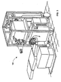
- an aberrometer or wavefront measurement system 10 is configured to provide a characterization of an input or object wavefront W of a subject eye 20 containing a cornea 22 and a retina 25.
- the wavefront measurement system 10 comprises an illumination optical system 30 that includes an illumination source 32 and may include one or more lenses 35 or other optical elements that are configured to direct light from the light source 32 to the eye 20 and to preferably focus the light onto the retina 25.
- the wavefront measurement system 10 also includes a computer or processor 36 that is used to control various components of the system 10, to collect input data from the system 10, and to make calculations regarding aberrations of the wavefronts W and/or W', aberrations of the system 10, and/or aberrations of the eye 20.
- the wavefront measurement system 10 also comprises an optical relay or image relay system 40 that is configured to receive and relay an input wavefront W from the eye 20.
- the input wavefront W is transformed by the relay system or telescope 40 into a wavefront W' that is received by a wavefront sensor 38 .
- the optical relay system 40 comprises a first lens 42 and a second lens 45.
- the first lens 42 of relay system 40 As the input wavefront W passes through the first lens 42 of relay system 40, light is generally directed or focused onto an internal focal plane. This light then passes through the second lens 45 to form the wavefront W', which is received by the wavefront sensor 38.
- at least one of the lenses 42, 45 may be replaced or supplemented by another optical element, for example, a diffractive optical element (DOE) or mirror.
- DOE diffractive optical element
- aberrations may be introduced into the wavefront W' that were not present in the input wavefront W, for example, by misalignment between the lenses 42, 45 in translation (dx, dy, dz) or rotation (d ⁇ x, d ⁇ y, d ⁇ z).
- aberrations may be introduced due to inherent optical characteristics of the optical relay system 40, for example, spherical aberrations introduced through the use of spherical lenses.
- the wavefront sensor 38 is a Shack-Hartmann wavefront sensor comprising a lenslet array 55 and a detector 60, which may be a CCD, CMOS, or similar type detector comprising an array of pixel elements. Alternatively, other types of wavefront sensors may be used, for example, an interferometer or phase diversity sensor arrangement.
- the test object is an eye 70 which produces the wavefront W at an exit pupil 75.
- the wavefront W is produced by focused light reflected by the eyes retina that passes through the eye.
- a mathematical relationship may be built of the wavefront aberrations in between the entrance pupil of the eye and the exit pupil of the relay system using Fourier polynomials and Zernike polynomials.
- the wavefront W also includes aberrations as it passes from the cornea of the eye to the pupil 75, which may be included in the aberrations calculated for the transferred wavefront W'. In other embodiments, aberrations introduced into the wavefront senor 50 may also be included in the wavefront analysis.
- more than one relay system may be disposed between the test object and the wavefront sensor 50, in which case an analysis according to embodiments of the present invention may be used to calculate aberrations introduced into the wavefront from the test object.
- the computer or processor 36 contains memory including instructions for calculating aberrations of the wavefront W', for example, by representing the wavefront W' as a polynomial, such as a Zernike polynomial or Fourier polynomial, for example as taught in USPN 6,609,793, 6,830,332.
- a polynomial such as a Zernike polynomial or Fourier polynomial
- the computer 36 may be a desktop or portable computer. Alternatively, the computer 36 may be incorporated into an electronic circuit board or chip containing on-board memory or in communications with separate external memory.
- a memory for the computer 36 contains value for certain parameters.
- the memory may contain one or more system error parameters.
- the system error parameters may include errors, aberrations, or misalignment information regarding the wavefront measurement system 10 and/or the optical relay system 40.
- the system error parameters may include coefficients of a polynomial equation representing an error or aberration, such as Zernike polynomial, a Taylor polynomial, or the like.
- a corneal refractive surgical system 100 includes a laser for performing a corneal refractive surgery such as a LASIK or PRK procedure, for example, as disclosed in USPN 6,964,659 .
- the surgical system 100 is provided with a treatment profile for a cornea based on the wavefront W' that is calculated based on the wavefront W and corrections or compensations for the transfer system 40 and/or cross-terms of the transfer system and the input wavefront W in accordance to embodiments discussed herein, or the like.
- a method or formulas are used in wavefront measurements using a confocal system from one point (pin hole or small aperture) to another conjugated point (pin hole or small aperture) instead of from one plane to another plane.
- a method may be applied for any other aerometer or device to measure accurately the aberrations of human eye or other optical system that uses a relay system before the wavefront sensor.
- the aberrations introduced into the object wavefront W may reduced or eliminated by adjusted, supplementing, or replacing optical elements of the relay system 40 or some other optical element of the measurement system 10.
- the final design of a wavefront measurement system or relay system 10 may be adjusted to reduce or eliminate the sensitivity to misalignment of certain optical elements of the system.
- a wavefront propagation theory may be used to derive mathematical expressions of the wavefront propagation through the optical relay system 40.
- the basis for the wavefront propagation may be based on:
- the wavefront transfer function or matrix may be given by:
- ray tracing simulations may be used to derive mathematical expressions of the wavefront propagation through the optical relay system 40, as discussed in further detail below.
- Embodiments of the present invention generally relate to optical imaging systems and methods of determining the image errors produced by such optical imaging systems.
- Embodiments of the present invention discussed below are for illustrative purposes and are not intended to limit the scope of the present invention. Aspects of the present invention are discussed below in conjunction with the "Slides” referenced therein and include with this disclosure.
- Output Input + System
- the relay system shown in FIG. 2 was used to demonstrate the effects of cross-talk in producing significant output error. It will be appreciated that this specific example is not meant to limit the scope of the present invention, but is given as a way of demonstrating the importance of using an analysis according to embodiments of the present invention in the design of optical systems, for example in the field of ophthalmic diagnostic.
- steps 1-3 of method 200 above various errors are introduced into the input and system shown in FIG. 2 .
- Input errors are shown in terms of Zernike coefficients in the second column of TABLE 1 below.
- the column labeled "OUTPUT” in TABLE 1 shows the resulting output after the system errors are subtracted out.
- the error in percent introduced by cross-talk is shown in the column in TABLE 1 labeled "Error Function 2".
- Error Function 2 As can be seen, these errors are significant for many of the Zernike terms.
- an additional error is introduce by way of displacement of the object plan by 10 millimeters. This amount of displacement error is typical in aberrometers used to measure aberrations of a subjects eye or cornea.
- a real relay system can introduce an input-dependent error due to the crosstalk between the input, the system, and the pupil diffraction to the output wavefront 2. Error could be introduced if the measured wavefront plane is not conjugated to the pupil plane because of changes in the wavefront during propagation 3.
- the quality of the relay optics and the alignment of the relay system are critical.
- Errors measuring lower order aberrations of the input wavefront may be relatively low, while those of higher order aberrations may be relatively high, as summarized in the following table: Not ignorable 1 2 (system RMS ⁇ ⁇ /4) Low order (up to 4th order) Determined by the system Up to 5% High order (above 4th order) Determined by the system Up to 50%
Landscapes
- Life Sciences & Earth Sciences (AREA)
- Health & Medical Sciences (AREA)
- Medical Informatics (AREA)
- Biophysics (AREA)
- Ophthalmology & Optometry (AREA)
- Engineering & Computer Science (AREA)
- Biomedical Technology (AREA)
- Heart & Thoracic Surgery (AREA)
- Physics & Mathematics (AREA)
- Molecular Biology (AREA)
- Surgery (AREA)
- Animal Behavior & Ethology (AREA)
- General Health & Medical Sciences (AREA)
- Public Health (AREA)
- Veterinary Medicine (AREA)
- Eye Examination Apparatus (AREA)
- Testing Of Optical Devices Or Fibers (AREA)
Claims (14)
- Système (10) pour procurer une vision, comprenant :un aberromètre configuré pour mesurer un front d'onde reçu, l'aberromètre comportant :un capteur (38) de front d'onde ; etun système optique de transfert pour transférer un front d'onde (w) d'entrée de sorte à fournir le front d'onde reçu au niveau de ou à proximité du capteur de front d'onde, le front d'onde (w) d'entrée étant le front d'onde introduit dans le système optique de transfert (30) et le front d'onde reçu étant le front d'onde reçu par le capteur (38) de front d'onde ;un processeur (36) en communication avec l'aberromètre;une mémoire lisible accouplée au processeur (36) contenant un ou plusieurs paramètres d'erreur système ;des instructions qui se trouvent dans la mémoire et à la disposition du processeur pour (1) déterminer au moins une aberration du front d'onde reçu et (2) calculer le front d'onde d'entrée sur la base du front d'onde reçu et de l'un ou plusieurs paramètres d'erreur système, caractérisé en ce que le processeur calcule le front d'onde (w) d'entrée à partir du front d'onde reçu en éliminant l'erreur système, où l'erreur système comprend un terme croisé du front d'onde (w) d'entrée et l'un ou plusieurs paramètres d'erreur système.
- Système de la revendication 1, dans lequel un front d'onde (w) d'entrée est disposé au niveau d'une pupille de l'oeil d'un sujet.
- Système de la revendication 1 ou 2, dans lequel l'un ou plusieurs paramètres d'erreur système sont calculés sur la base d'une ou plusieurs aberrations du front d'onde (w) d'entré et/ou
où l'un ou plusieurs paramètres d'erreur système sont calculés sur la base d'un ou de plusieurs paramètres d'entrée, les paramètres d'entrée étant une ou plusieurs aberrations du système optique de transfert (30) et un désalignement d'un ou de plusieurs composants de l'aberromètre. - Système de la revendication 1 à 3, dans lequel l'erreur système est représentée par une équation polynomiale.
- Système de la revendication 4, dans lequel l'équation polynomiale comporte une pluralité de coefficients, les coefficients étant des coefficients de Zernike ou des coefficients de Fourier.
- Système selon l'une quelconque des revendications 1 à 5, dans lequel l'aberromètre comprend en outre :une source d'illumination (32) ;un système optique d'illumination (30) pour diriger la lumière provenant de la source d'illumination (32) vers l'oeil (20) du sujet pour créer un front d'onde (w) d'entrée à partir de la lumière réfléchie par l'oeil du sujet.
- Système de la revendication 6, dans lequel le capteur (38) de front d'onde comprend un détecteur (60) et une pluralité de microlentilles (55) pour recevoir le front d'onde reçu et focaliser la lumière provenant du front d'onde reçu sur le détecteur (60).
- Système de la revendication 6 ou 7, dans lequel l'erreur système comporte des aberrations, les aberrations étant des aberrations du système optique de transfert.
- Système de la revendication 6 ou 7, dans lequel l'erreur système comporte des aberrations du système de transfert optique.
- Système selon l'une quelconque des revendications 1 à 9, dans lequel les paramètres d'erreur système sont basés sur la formule d'approximation de Fresnel-Kirchhoff.
- Système selon l'une quelconque des revendications 1 à 10, dans lequel le système comprend en outre un système d'ablation configuré pour modifier une cornée de l'oeil (20) du sujet sur la base du front d'onde reçu et de l'un ou plusieurs paramètres d'erreur système.
- Procédé destiné à procurer la vision, comprenant le fait :de fournir un front d'onde d'entrée situé à un plan d'entrée ;de fournir un aberromètre configuré pour mesurer un front d'onde reçu, l'aberromètre comportant :un ou plusieurs paramètres d'erreur système ;un capteur (38) de front d'onde ; etun système optique de transfert ;de former un front d'onde reçu au niveau de ou à proximité du capteur de front d'onde en propageant le front d'onde (w) d'entrée à travers le système optique de transfert, le front d'onde (w) d'entrée étant le front d'onde introduit dans le système optique de transfert (30) et le front d'onde reçu étant le front d'onde reçu par le capteur (38) de front d'onde ;de déterminer au moins une aberration du front d'onde reçu, caractérisé par le faitde calculer le front d'onde (w) d'entrée à partir du front d'onde reçu en éliminant l'erreur système, où l'erreur système comprend un terme croisé du front d'onde d'entrée et l'un ou plusieurs paramètres d'erreur système.
- Procédé de conception d'un système optique, comprenant le fait :de fournir un système selon la revendication 1, le système comportant en outre un plan d'entrée, un plan de sortie ; le procédé comprenant en outre le fait :de calculer une fonction d'erreur système ;d'ajuster un paramètre système ; de répéter le calcul et l'ajustement jusqu'à ce que l'erreur soit inférieure à un seuil.
- Procédé de la revendication 13, dans lequel le fait de calculer la fonction de l'erreur système est basé sur une formule d'approximation de Fresnel-Kirchhoff.
Applications Claiming Priority (3)
| Application Number | Priority Date | Filing Date | Title |
|---|---|---|---|
| US98435507P | 2007-10-31 | 2007-10-31 | |
| US2889008P | 2008-02-14 | 2008-02-14 | |
| PCT/US2008/082162 WO2009059256A1 (fr) | 2007-10-31 | 2008-11-18 | Systèmes et logiciels pour le traitement de données de fronts d'onde, la correction de vision et d'autres applications |
Publications (2)
| Publication Number | Publication Date |
|---|---|
| EP2211684A1 EP2211684A1 (fr) | 2010-08-04 |
| EP2211684B1 true EP2211684B1 (fr) | 2011-05-11 |
Family
ID=40317750
Family Applications (1)
| Application Number | Title | Priority Date | Filing Date |
|---|---|---|---|
| EP08845610A Not-in-force EP2211684B1 (fr) | 2007-10-31 | 2008-11-18 | Systèmes et logiciels pour le traitement de données de fronts d'onde, la correction de vision et d'autres applications |
Country Status (6)
| Country | Link |
|---|---|
| US (2) | US7654672B2 (fr) |
| EP (1) | EP2211684B1 (fr) |
| AT (1) | ATE508677T1 (fr) |
| AU (1) | AU2008318401B2 (fr) |
| CA (1) | CA2704415C (fr) |
| WO (1) | WO2009059256A1 (fr) |
Families Citing this family (7)
| Publication number | Priority date | Publication date | Assignee | Title |
|---|---|---|---|---|
| CA2559324A1 (fr) * | 2004-03-11 | 2005-09-22 | Nano-Or Technologies (Israel) Ltd. | Procedes et appareils de manipulation de fronts d'ondes et mesures en 3d ameliorees |
| US8506083B2 (en) | 2011-06-06 | 2013-08-13 | Clarity Medical Systems, Inc. | Compact wavefront sensor module and its attachment to or integration with an ophthalmic instrument |
| US8356900B2 (en) | 2006-01-20 | 2013-01-22 | Clarity Medical Systems, Inc. | Large diopter range real time sequential wavefront sensor |
| US7654672B2 (en) * | 2007-10-31 | 2010-02-02 | Abbott Medical Optics Inc. | Systems and software for wavefront data processing, vision correction, and other applications |
| WO2013106591A1 (fr) | 2012-01-10 | 2013-07-18 | Digitalvision, Llc | Optimiseur de lentille intraoculaire |
| US8888289B2 (en) | 2012-01-10 | 2014-11-18 | Digitalvision, Llc | Refractometer with a remote wavefront generator |
| AU2013341289B2 (en) | 2012-11-07 | 2015-09-17 | Clarity Medical Systems, Inc. | Apparatus and method for operating a real time large diopter range sequential wavefront sensor |
Family Cites Families (12)
| Publication number | Priority date | Publication date | Assignee | Title |
|---|---|---|---|---|
| FR2791548B1 (fr) * | 1999-04-01 | 2001-07-06 | Univ Paris Vii Denis Diderot | Dispositif d'observation d'un corps a haute resolution |
| US6050687A (en) * | 1999-06-11 | 2000-04-18 | 20/10 Perfect Vision Optische Geraete Gmbh | Method and apparatus for measurement of the refractive properties of the human eye |
| US7044944B2 (en) * | 2000-03-22 | 2006-05-16 | Alcon Refractivehorizons, Inc. | Optimization of ablation correction of an optical system and associated methods |
| US6609793B2 (en) * | 2000-05-23 | 2003-08-26 | Pharmacia Groningen Bv | Methods of obtaining ophthalmic lenses providing the eye with reduced aberrations |
| SE0101293D0 (sv) * | 2001-04-11 | 2001-04-11 | Pharmacia Groningen Bv | Technical field of the invention |
| US6637884B2 (en) * | 2001-12-14 | 2003-10-28 | Bausch & Lomb Incorporated | Aberrometer calibration |
| US6809793B1 (en) | 2002-01-16 | 2004-10-26 | Advanced Micro Devices, Inc. | System and method to monitor reticle heating |
| US6964659B2 (en) * | 2002-05-30 | 2005-11-15 | Visx, Incorporated | Thermal modeling for reduction of refractive laser surgery times |
| DE10333794A1 (de) * | 2003-07-24 | 2005-03-03 | Technovision Gmbh | Verfahren und Vorrichtung zur Online-Kontaktlinsenbewertung |
| US20050105044A1 (en) * | 2003-11-14 | 2005-05-19 | Laurence Warden | Lensometers and wavefront sensors and methods of measuring aberration |
| US20080074614A1 (en) * | 2006-09-25 | 2008-03-27 | Richard Alan Leblanc | Method and system for pupil acquisition |
| US7654672B2 (en) * | 2007-10-31 | 2010-02-02 | Abbott Medical Optics Inc. | Systems and software for wavefront data processing, vision correction, and other applications |
-
2008
- 2008-10-31 US US12/263,433 patent/US7654672B2/en active Active
- 2008-11-18 CA CA2704415A patent/CA2704415C/fr not_active Expired - Fee Related
- 2008-11-18 AU AU2008318401A patent/AU2008318401B2/en not_active Ceased
- 2008-11-18 EP EP08845610A patent/EP2211684B1/fr not_active Not-in-force
- 2008-11-18 AT AT08845610T patent/ATE508677T1/de not_active IP Right Cessation
- 2008-11-18 WO PCT/US2008/082162 patent/WO2009059256A1/fr not_active Ceased
-
2009
- 2009-12-30 US US12/650,130 patent/US8162480B2/en not_active Expired - Fee Related
Also Published As
| Publication number | Publication date |
|---|---|
| US7654672B2 (en) | 2010-02-02 |
| US20100103378A1 (en) | 2010-04-29 |
| US20090109403A1 (en) | 2009-04-30 |
| ATE508677T1 (de) | 2011-05-15 |
| CA2704415C (fr) | 2014-09-09 |
| AU2008318401B2 (en) | 2014-02-06 |
| CA2704415A1 (fr) | 2009-05-07 |
| AU2008318401A1 (en) | 2009-05-07 |
| WO2009059256A1 (fr) | 2009-05-07 |
| EP2211684A1 (fr) | 2010-08-04 |
| US8162480B2 (en) | 2012-04-24 |
Similar Documents
| Publication | Publication Date | Title |
|---|---|---|
| EP2211684B1 (fr) | Systèmes et logiciels pour le traitement de données de fronts d'onde, la correction de vision et d'autres applications | |
| US6578963B2 (en) | Wavefront sensor for objective measurement of an optical system and associated methods | |
| AU747840B2 (en) | Apparatus and method for measuring vision defects of a human eye | |
| EP1210003B1 (fr) | Appareil et procede de mesure et de correction objectives de systemes optiques par analyse de front d'ondes | |
| CA2275762C (fr) | Dispositif servant a ameliorer la vision et la resolution d'images retiniennes | |
| US6598975B2 (en) | Apparatus and method for measuring vision defects of a human eye | |
| EP1619999B1 (fr) | Capteur a front d'onde portable compact | |
| CA2425256A1 (fr) | Determination de refraction oculaire a partir de donnees d'aberration de front d'ondes | |
| MXPA01013364A (es) | Filtro especial para mejorar las imagenes hartmann-shack, y metodos asociados. | |
| EP1593945A1 (fr) | Capteur de front d'onde et relais pour une mesure optique et méthodes associées. | |
| Navarro | Measurement and correction of optical aberrations in human eyes |
Legal Events
| Date | Code | Title | Description |
|---|---|---|---|
| PUAI | Public reference made under article 153(3) epc to a published international application that has entered the european phase |
Free format text: ORIGINAL CODE: 0009012 |
|
| 17P | Request for examination filed |
Effective date: 20100430 |
|
| AK | Designated contracting states |
Kind code of ref document: A1 Designated state(s): AT BE BG CH CY CZ DE DK EE ES FI FR GB GR HR HU IE IS IT LI LT LU LV MC MT NL NO PL PT RO SE SI SK TR |
|
| AX | Request for extension of the european patent |
Extension state: AL BA MK RS |
|
| RIN1 | Information on inventor provided before grant (corrected) |
Inventor name: ZHAO, HUAWEI Inventor name: LI, CHEN |
|
| GRAP | Despatch of communication of intention to grant a patent |
Free format text: ORIGINAL CODE: EPIDOSNIGR1 |
|
| DAX | Request for extension of the european patent (deleted) | ||
| GRAS | Grant fee paid |
Free format text: ORIGINAL CODE: EPIDOSNIGR3 |
|
| GRAA | (expected) grant |
Free format text: ORIGINAL CODE: 0009210 |
|
| AK | Designated contracting states |
Kind code of ref document: B1 Designated state(s): AT BE BG CH CY CZ DE DK EE ES FI FR GB GR HR HU IE IS IT LI LT LU LV MC MT NL NO PL PT RO SE SI SK TR |
|
| REG | Reference to a national code |
Ref country code: GB Ref legal event code: FG4D |
|
| REG | Reference to a national code |
Ref country code: CH Ref legal event code: EP |
|
| REG | Reference to a national code |
Ref country code: IE Ref legal event code: FG4D |
|
| REG | Reference to a national code |
Ref country code: DE Ref legal event code: R096 Ref document number: 602008006930 Country of ref document: DE Effective date: 20110622 |
|
| REG | Reference to a national code |
Ref country code: NL Ref legal event code: T3 |
|
| REG | Reference to a national code |
Ref country code: CH Ref legal event code: NV Representative=s name: NOVAGRAAF INTERNATIONAL SA |
|
| REG | Reference to a national code |
Ref country code: SE Ref legal event code: TRGR |
|
| PG25 | Lapsed in a contracting state [announced via postgrant information from national office to epo] |
Ref country code: PT Free format text: LAPSE BECAUSE OF FAILURE TO SUBMIT A TRANSLATION OF THE DESCRIPTION OR TO PAY THE FEE WITHIN THE PRESCRIBED TIME-LIMIT Effective date: 20110912 Ref country code: LT Free format text: LAPSE BECAUSE OF FAILURE TO SUBMIT A TRANSLATION OF THE DESCRIPTION OR TO PAY THE FEE WITHIN THE PRESCRIBED TIME-LIMIT Effective date: 20110511 Ref country code: NO Free format text: LAPSE BECAUSE OF FAILURE TO SUBMIT A TRANSLATION OF THE DESCRIPTION OR TO PAY THE FEE WITHIN THE PRESCRIBED TIME-LIMIT Effective date: 20110811 |
|
| PG25 | Lapsed in a contracting state [announced via postgrant information from national office to epo] |
Ref country code: IS Free format text: LAPSE BECAUSE OF FAILURE TO SUBMIT A TRANSLATION OF THE DESCRIPTION OR TO PAY THE FEE WITHIN THE PRESCRIBED TIME-LIMIT Effective date: 20110911 Ref country code: ES Free format text: LAPSE BECAUSE OF FAILURE TO SUBMIT A TRANSLATION OF THE DESCRIPTION OR TO PAY THE FEE WITHIN THE PRESCRIBED TIME-LIMIT Effective date: 20110822 Ref country code: SI Free format text: LAPSE BECAUSE OF FAILURE TO SUBMIT A TRANSLATION OF THE DESCRIPTION OR TO PAY THE FEE WITHIN THE PRESCRIBED TIME-LIMIT Effective date: 20110511 Ref country code: BE Free format text: LAPSE BECAUSE OF FAILURE TO SUBMIT A TRANSLATION OF THE DESCRIPTION OR TO PAY THE FEE WITHIN THE PRESCRIBED TIME-LIMIT Effective date: 20110511 Ref country code: AT Free format text: LAPSE BECAUSE OF FAILURE TO SUBMIT A TRANSLATION OF THE DESCRIPTION OR TO PAY THE FEE WITHIN THE PRESCRIBED TIME-LIMIT Effective date: 20110511 Ref country code: FI Free format text: LAPSE BECAUSE OF FAILURE TO SUBMIT A TRANSLATION OF THE DESCRIPTION OR TO PAY THE FEE WITHIN THE PRESCRIBED TIME-LIMIT Effective date: 20110511 Ref country code: GR Free format text: LAPSE BECAUSE OF FAILURE TO SUBMIT A TRANSLATION OF THE DESCRIPTION OR TO PAY THE FEE WITHIN THE PRESCRIBED TIME-LIMIT Effective date: 20110812 Ref country code: LV Free format text: LAPSE BECAUSE OF FAILURE TO SUBMIT A TRANSLATION OF THE DESCRIPTION OR TO PAY THE FEE WITHIN THE PRESCRIBED TIME-LIMIT Effective date: 20110511 Ref country code: CY Free format text: LAPSE BECAUSE OF FAILURE TO SUBMIT A TRANSLATION OF THE DESCRIPTION OR TO PAY THE FEE WITHIN THE PRESCRIBED TIME-LIMIT Effective date: 20110511 |
|
| PG25 | Lapsed in a contracting state [announced via postgrant information from national office to epo] |
Ref country code: EE Free format text: LAPSE BECAUSE OF FAILURE TO SUBMIT A TRANSLATION OF THE DESCRIPTION OR TO PAY THE FEE WITHIN THE PRESCRIBED TIME-LIMIT Effective date: 20110511 Ref country code: CZ Free format text: LAPSE BECAUSE OF FAILURE TO SUBMIT A TRANSLATION OF THE DESCRIPTION OR TO PAY THE FEE WITHIN THE PRESCRIBED TIME-LIMIT Effective date: 20110511 |
|
| PG25 | Lapsed in a contracting state [announced via postgrant information from national office to epo] |
Ref country code: PL Free format text: LAPSE BECAUSE OF FAILURE TO SUBMIT A TRANSLATION OF THE DESCRIPTION OR TO PAY THE FEE WITHIN THE PRESCRIBED TIME-LIMIT Effective date: 20110511 Ref country code: RO Free format text: LAPSE BECAUSE OF FAILURE TO SUBMIT A TRANSLATION OF THE DESCRIPTION OR TO PAY THE FEE WITHIN THE PRESCRIBED TIME-LIMIT Effective date: 20110511 Ref country code: SK Free format text: LAPSE BECAUSE OF FAILURE TO SUBMIT A TRANSLATION OF THE DESCRIPTION OR TO PAY THE FEE WITHIN THE PRESCRIBED TIME-LIMIT Effective date: 20110511 Ref country code: DK Free format text: LAPSE BECAUSE OF FAILURE TO SUBMIT A TRANSLATION OF THE DESCRIPTION OR TO PAY THE FEE WITHIN THE PRESCRIBED TIME-LIMIT Effective date: 20110511 |
|
| PLBE | No opposition filed within time limit |
Free format text: ORIGINAL CODE: 0009261 |
|
| STAA | Information on the status of an ep patent application or granted ep patent |
Free format text: STATUS: NO OPPOSITION FILED WITHIN TIME LIMIT |
|
| 26N | No opposition filed |
Effective date: 20120214 |
|
| PG25 | Lapsed in a contracting state [announced via postgrant information from national office to epo] |
Ref country code: IT Free format text: LAPSE BECAUSE OF FAILURE TO SUBMIT A TRANSLATION OF THE DESCRIPTION OR TO PAY THE FEE WITHIN THE PRESCRIBED TIME-LIMIT Effective date: 20110511 Ref country code: HR Free format text: LAPSE BECAUSE OF FAILURE TO SUBMIT A TRANSLATION OF THE DESCRIPTION OR TO PAY THE FEE WITHIN THE PRESCRIBED TIME-LIMIT Effective date: 20111123 |
|
| REG | Reference to a national code |
Ref country code: DE Ref legal event code: R097 Ref document number: 602008006930 Country of ref document: DE Effective date: 20120214 |
|
| PG25 | Lapsed in a contracting state [announced via postgrant information from national office to epo] |
Ref country code: MC Free format text: LAPSE BECAUSE OF NON-PAYMENT OF DUE FEES Effective date: 20111130 |
|
| REG | Reference to a national code |
Ref country code: IE Ref legal event code: MM4A |
|
| PG25 | Lapsed in a contracting state [announced via postgrant information from national office to epo] |
Ref country code: IE Free format text: LAPSE BECAUSE OF NON-PAYMENT OF DUE FEES Effective date: 20111118 |
|
| PG25 | Lapsed in a contracting state [announced via postgrant information from national office to epo] |
Ref country code: MT Free format text: LAPSE BECAUSE OF FAILURE TO SUBMIT A TRANSLATION OF THE DESCRIPTION OR TO PAY THE FEE WITHIN THE PRESCRIBED TIME-LIMIT Effective date: 20110511 |
|
| PG25 | Lapsed in a contracting state [announced via postgrant information from national office to epo] |
Ref country code: LU Free format text: LAPSE BECAUSE OF NON-PAYMENT OF DUE FEES Effective date: 20111118 |
|
| PG25 | Lapsed in a contracting state [announced via postgrant information from national office to epo] |
Ref country code: BG Free format text: LAPSE BECAUSE OF FAILURE TO SUBMIT A TRANSLATION OF THE DESCRIPTION OR TO PAY THE FEE WITHIN THE PRESCRIBED TIME-LIMIT Effective date: 20110811 |
|
| PG25 | Lapsed in a contracting state [announced via postgrant information from national office to epo] |
Ref country code: TR Free format text: LAPSE BECAUSE OF FAILURE TO SUBMIT A TRANSLATION OF THE DESCRIPTION OR TO PAY THE FEE WITHIN THE PRESCRIBED TIME-LIMIT Effective date: 20110511 |
|
| PG25 | Lapsed in a contracting state [announced via postgrant information from national office to epo] |
Ref country code: HU Free format text: LAPSE BECAUSE OF FAILURE TO SUBMIT A TRANSLATION OF THE DESCRIPTION OR TO PAY THE FEE WITHIN THE PRESCRIBED TIME-LIMIT Effective date: 20110511 |
|
| PG25 | Lapsed in a contracting state [announced via postgrant information from national office to epo] |
Ref country code: HR Free format text: LAPSE BECAUSE OF FAILURE TO SUBMIT A TRANSLATION OF THE DESCRIPTION OR TO PAY THE FEE WITHIN THE PRESCRIBED TIME-LIMIT Effective date: 20110511 |
|
| REG | Reference to a national code |
Ref country code: FR Ref legal event code: PLFP Year of fee payment: 8 |
|
| REG | Reference to a national code |
Ref country code: FR Ref legal event code: PLFP Year of fee payment: 9 |
|
| PGFP | Annual fee paid to national office [announced via postgrant information from national office to epo] |
Ref country code: NL Payment date: 20161028 Year of fee payment: 9 |
|
| PGFP | Annual fee paid to national office [announced via postgrant information from national office to epo] |
Ref country code: SE Payment date: 20161007 Year of fee payment: 9 |
|
| REG | Reference to a national code |
Ref country code: FR Ref legal event code: PLFP Year of fee payment: 10 |
|
| REG | Reference to a national code |
Ref country code: FR Ref legal event code: PLFP Year of fee payment: 11 |
|
| PGFP | Annual fee paid to national office [announced via postgrant information from national office to epo] |
Ref country code: FR Payment date: 20180223 Year of fee payment: 11 |
|
| REG | Reference to a national code |
Ref country code: SE Ref legal event code: EUG |
|
| REG | Reference to a national code |
Ref country code: NL Ref legal event code: MM Effective date: 20171201 |
|
| PG25 | Lapsed in a contracting state [announced via postgrant information from national office to epo] |
Ref country code: SE Free format text: LAPSE BECAUSE OF NON-PAYMENT OF DUE FEES Effective date: 20171119 |
|
| PG25 | Lapsed in a contracting state [announced via postgrant information from national office to epo] |
Ref country code: NL Free format text: LAPSE BECAUSE OF NON-PAYMENT OF DUE FEES Effective date: 20171201 |
|
| REG | Reference to a national code |
Ref country code: CH Ref legal event code: PFA Owner name: JOHNSON AND JOHNSON SURGICAL VISION, INC., US Free format text: FORMER OWNER: ABBOTT MEDICAL OPTICS INC., US |
|
| REG | Reference to a national code |
Ref country code: DE Ref legal event code: R081 Ref document number: 602008006930 Country of ref document: DE Owner name: JOHNSON & JOHNSON SURGICAL VISION, INC. (N. D., US Free format text: FORMER OWNER: ABBOTT MEDICAL OPTICS INC., SANTA ANA, CALIF., US Ref country code: DE Ref legal event code: R082 Ref document number: 602008006930 Country of ref document: DE |
|
| PGFP | Annual fee paid to national office [announced via postgrant information from national office to epo] |
Ref country code: DE Payment date: 20181106 Year of fee payment: 11 |
|
| PGFP | Annual fee paid to national office [announced via postgrant information from national office to epo] |
Ref country code: GB Payment date: 20181114 Year of fee payment: 11 Ref country code: CH Payment date: 20181115 Year of fee payment: 11 |
|
| REG | Reference to a national code |
Ref country code: DE Ref legal event code: R119 Ref document number: 602008006930 Country of ref document: DE |
|
| REG | Reference to a national code |
Ref country code: CH Ref legal event code: PL |
|
| PG25 | Lapsed in a contracting state [announced via postgrant information from national office to epo] |
Ref country code: LI Free format text: LAPSE BECAUSE OF NON-PAYMENT OF DUE FEES Effective date: 20191130 Ref country code: CH Free format text: LAPSE BECAUSE OF NON-PAYMENT OF DUE FEES Effective date: 20191130 |
|
| GBPC | Gb: european patent ceased through non-payment of renewal fee |
Effective date: 20191118 |
|
| PG25 | Lapsed in a contracting state [announced via postgrant information from national office to epo] |
Ref country code: FR Free format text: LAPSE BECAUSE OF NON-PAYMENT OF DUE FEES Effective date: 20191130 Ref country code: DE Free format text: LAPSE BECAUSE OF NON-PAYMENT OF DUE FEES Effective date: 20200603 Ref country code: GB Free format text: LAPSE BECAUSE OF NON-PAYMENT OF DUE FEES Effective date: 20191118 |