EP2211562A1 - Loudspeaker installation - Google Patents
Loudspeaker installation Download PDFInfo
- Publication number
- EP2211562A1 EP2211562A1 EP09151095A EP09151095A EP2211562A1 EP 2211562 A1 EP2211562 A1 EP 2211562A1 EP 09151095 A EP09151095 A EP 09151095A EP 09151095 A EP09151095 A EP 09151095A EP 2211562 A1 EP2211562 A1 EP 2211562A1
- Authority
- EP
- European Patent Office
- Prior art keywords
- pillar
- driver
- automobile
- volume
- wall
- Prior art date
- Legal status (The legal status is an assumption and is not a legal conclusion. Google has not performed a legal analysis and makes no representation as to the accuracy of the status listed.)
- Withdrawn
Links
Images


Classifications
-
- H—ELECTRICITY
- H04—ELECTRIC COMMUNICATION TECHNIQUE
- H04R—LOUDSPEAKERS, MICROPHONES, GRAMOPHONE PICK-UPS OR LIKE ACOUSTIC ELECTROMECHANICAL TRANSDUCERS; ELECTRIC HEARING AIDS; PUBLIC ADDRESS SYSTEMS
- H04R5/00—Stereophonic arrangements
- H04R5/02—Spatial or constructional arrangements of loudspeakers
-
- B—PERFORMING OPERATIONS; TRANSPORTING
- B60—VEHICLES IN GENERAL
- B60R—VEHICLES, VEHICLE FITTINGS, OR VEHICLE PARTS, NOT OTHERWISE PROVIDED FOR
- B60R11/00—Arrangements for holding or mounting articles, not otherwise provided for
- B60R11/02—Arrangements for holding or mounting articles, not otherwise provided for for radio sets, television sets, telephones, or the like; Arrangement of controls thereof
- B60R11/0217—Arrangements for holding or mounting articles, not otherwise provided for for radio sets, television sets, telephones, or the like; Arrangement of controls thereof for loud-speakers
Definitions
- the present invention relates to an A-pillar for an automobile, the A-pillar is provided with an electro acoustical transducer arrangement.
- the present invention also relates to an automobile having at least one such A-pillar.
- a loudspeaker enclosure is a cabinet designed to transmit sound to the listener via mounted loudspeaker drive units. Generally it is believed that the role of the enclosure is to prevent the out-of-phase sound waves from the rear of the speaker from combining with the in-phase sound waves from the front of the speaker. Such mixing results in interference patterns and cancellation, causing the efficiency of the speaker to be reduced, particularly at low frequencies where the wavelengths are large enough that interference will affect substantially the entire listening area.
- the present invention at least partly solves, or reduces, some of the above mentioned drawbacks. More specifically they are at least partly solved, or reduced, by an A-pillar for an automobile, the A-pillar having at least one electro acoustical transducer arrangement, such as a speaker, preferably a subwoofer.
- the electro acoustical transducer arrangement comprises a driver and a driver enclosure.
- the A-pillar comprises at least one wall defining a volume, wherein the driver enclosure is at least partly defined or at least partly contained by at least a part of the wall and the volume of the A-pillar.
- the present invention provides for a space saving enclosure, which enables an electro acoustical transducer arrangement to be arranged in the front area of an automobile while reducing the risk of damaging the electro acoustical transducer, for example by keeping it in a dry zone. It further provides a high coefficient of utilization of the available space in the automobile. Furthermore, the installation of the electro acoustical transducer is improved as this can be done at a relatively early stage in the assembly process of an automobile.
- the driver enclosure can be contained or defined by the at least a part of the wall and the volume of the A-pillar.
- the volume of the A-pillar is the interior volume of the A-pillar. This provides for a large volume and easy installation.
- the volume can optionally be formed by a cavity in the A-pillar.
- the driver can be a subwoofer, advantageously operating in the low frequency scale, such as below 200 Hz, 190 Hz, 180 Hz, 170 Hz, 160 Hz, 150 Hz, 140 Hz or lower. This has been found to be especially advantageous together with an A-pillar and the vast volume which is required when using low frequency drivers and especially when using the interior volume of the A-pillar.
- the A-pillar advantageously comprises a metal.
- at least one of the A-pillar's walls can advantageously be made from metal, such as steel.
- the wall of the A-pillar can comprise at least one aperture, the driver can then be arranged to substantially cover the aperture. If the driver comprises a diaphragm, the diaphragm can be positioned to face away or optionally to face towards the interior of the A-pillar.
- the frame, basket or chassis extends away from the interior volume or cavity.
- the frame, basket or chassis is at least partly inserted into the aperture.
- the A-pillar can comprise at least 1 driver, at least 2, 3, 4 or more drivers.
- the A-pillar can comprise different kinds of drivers such as subwoofers, woofers, tweeters or the like, although it should be noted that drivers operable in the low frequency area, i.e. below 200 Hz are considered to be most favourable.
- the A-pillar has a substantially air tight sealing member arranged between the driver and the A-pillar. This reduces or eliminates the risk of stray sound from the driver enclosure cancelling sound inside the passenger compartment. Sound absorbing material inside or optionally outside of the driver enclosure can also be provided.
- the present invention also relates to an automobile comprising at least one, preferably two, A-pillars having at least one electro acoustical transducer arrangement as described herein.
- FIG 1 shows a schematic figure of an automobile 10 as seen from above.
- the automobile 10 has a passenger compartment 11 provided with a set of speakers 12 positioned at selected locations inside the passenger compartment 11.
- the automobile has a longitudinal direction L, a transverse direction T and a height H, a left side LS, a right side RS, a front F, and a back B.
- the automobile 10 further has a first and a second front side door 13, 14, a first and a second back side door 15, 16, and a rear compartment door 17.
- each of the front and back doors 13, 14, 15, 16 are equipped with speakers 12.
- each front and back door 13, 14, 15, 16 is equipped with a 2.5 cm (1 ") tweeter and a 7.6 cm (3") midrange speaker.
- the sound system of the automobile 10 further comprises, in the non-limiting example shown in figure 1 , a first and a second 15.2 cm (6.5") subwoofer 21, 22.
- the first and the second subwoofers 21, 22 are for example subwoofers, with a diameter of 15.2 cm (6.5"), nominal power handling of 75 watt, peak power handling 130 watt, sensitivity 88 dB, impedance 4 ohm. Generally the subwoofer will operate below 200 Hz. Subwoofers with a 10.2 cm (4"), 12.7 cm (5"), 20.3 cm (8"), 25.4 cm (10"), 30.5 cm (12"), 38.1 cm (15") and 45.7 cm (18") diameter can also be used.
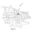
- Figure 2 shows parts of the passenger compartment seen without the interior details such as the dashboard, the steering wheel, the seats or the like. These kind of interior items have been removed to more clearly illustrate the present invention.
- Figure 2 shows parts of a left side A-pillar 30, which is in the proximity of the left side LS of the automobile 10, in this case closest to the driver's side of the automobile 10.
- the A-pillar 30 can be separate or integrated into the structure of the body of the automobile 10.
- the A-pillar can for example be similar to the one described in the US patent no. 7,267,394 B1 .
- the subwoofer 21 is mounted in/on the A-pillar using the interior volume of the A-pillar 30 as an enclosure, sometimes also referred to as the speaker box.
- the A-pillar can be arranged with a plurality of subwoofers, for example 1, 2, 3, 4, or more subwoofers 21.
- the position of the subwoofer 21 can be close to the floor 31 of the automobile for example, although in figure 2 it is positioned at a height H of about 40-50 cm above the floor 31 of the automobile 10.
- Figure 2 further shows the interior of the front left door 13, parts of a B-pillar 18 on the right side RS of the automobile 10.
- An intermediate wall 19 separates the engine compartment 20 from the passenger compartment 11.
- a dashboard (not shown) can thereafter be arranged to cover the intermediate wall 19 and the subwoofer 21.
- Figure 2 also shows part of a right side A-pillar 30RS having a subwoofer 21 as described above (not shown).
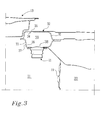
- Figure 3 shows parts of a cross section of the A-pillar 30 on the left side LS of the automobile 10.
- the cross section is in the horizontal plane, hence figure 3 shows the A-pillar as seen from above, the same view as the automobile is shown in figure 1 .
- the A-pillar 30 is in the shown embodiment according to the present invention, made form a first and a second metal wall 32, 33 welded together.
- Each of the first and second metal wall 32, 33 comprises an inner and an outer surface 34, 35, 36, 37.
- the second metal wall 33 is arranged closest to the passenger compartment 11 while the first metal wall 32 is arranged furthest away from the passenger compartment 11.
- the second metal wall 33 is equipped with an aperture 38 above which the subwoofer 21 is superpositioned.
- the first and the second metal wall 32, 33 further defines an interior volume 39 of the A-pillar 30.
- the front left door 13 is arranged in the proximity of the A-pillar 31 on the left side LS.
- the intermediate wall 19 is arranged adjacent the engine compartment 20.
- the subwoofer 21, more generally referred to as a driver generally comprises a diaphragm 23 with a dust cap 24, the diaphragm 23 is flexibly arranged on a frame 25, sometimes referred to as a basket or a chassis.
- the frame 25 comprises a circumferential flange extending around the diaphragm 23 for attachment to the second metal wall 33 via bolts or screws 29 and in the proximity of the aperture 38.
- the A-pillar 30, or at least the parts of the A-pillar 30, forms an enclosure, also referred to as a speaker box, for the subwoofer 21.
- An air tight sealing member 50 is arranged between the subwoofer 21 and the second metal wall 33 of the A-pillar 30, to prevent any sound waves from escaping the interior 39 of the A-pillar 30.
- the A-pillar 30 provide a place to mount the first subwoofer 21 but also prevents, or at least reduces, sound waves from the front of the first subwoofer 21 from interfering destructively with those from the back. Doing so typically causes cancellations, e.g. an acoustic short circuit, and significantly improves the level and sound quality at low frequencies and especially at frequencies below 200 Hz.
- front of the subwoofer 21, or when referred to as a driver, is meant that side on which the diaphragm is positioned, in this case diaphragm 23, while back is the opposite side, in this case that side of the pole piece, spider and a voice coil 26.
- the diaphragm 23 is positioned substantially in the plane of the second metal wall 33 at the aperture 38 of the A-pillar 30 with the frame 25 facing away from the second metal wall 33 extending towards the interior of the passenger compartment 11. This has been shown to be very space saving, since the interior volume 39 of the A-pillar is usually quite restricted.
- the frame 25 extends into the enclosure, in this case it is the interior volume 39 of the A-pillar, which defines the enclosure together with the metal walls 32, 33.
- the A-pillar 30, functioning as an enclosure to the driver 21, contains the radiation from the pole piece, spider and a voice coil 26 thereby preventing transmission of the sound emitted from the rear of the subwoofer 21 by confining the sound in a substantially rigid box, defined by the interior volume 39 of the A-pillar 30 and the surrounding metal walls 32, 33.
- the thickness T of the first and second metal wall 32, 33, i.e. the wall of the A-pillar 30, can be adapted to reduce transmission of sound through the first and second metal wall 32, 33 of the A-pillar 30 while at the same time provide for a rigid safe A-pillar structure for the automobile 10.
- Each of the inner surfaces 34, 36 of the first and second metal wall 32, 33 can be arranged with lossy wall material, internal bracings, visco-elastic materials (e.g. mineral loaded bitumen), coatings, or thin lead sheets to prevent sound form penetrating the walls of the A-pillar 30.
- internal absorption material 40 can be positioned within the A-pillar 30, for absorbing the sound. Examples of absorbing material, often called "damping" material are; fiberglass, wool or synthetic fiber batting, combinations thereof, or the like.
- the internal shape of the interior volume 39 of the A-pillar 30 can also be designed to reduce or reflect sound away from the frame 25 and the diaphragm 23 to a location where it can be absorbed or at least provide less interference.
- protrusions 41 can be arranged on the inner surface 34 of the first metal wall 32, and/or on the inner surface 36 of the second metal wall 33.
- the protrusions 41 can be designed to that they also have a supportive function to the rigidity of the A-pillar 30.
- the protrusions 41 can be formed by folds in the A-pillar or as attached material pieces to the inner surface 34. Combinations of protrusions formed from the material of the A-pillar or from separate material are of course also possible.
- One main purpose of the protrusions is to reflect sound to a location where it can be absorbed or at least provide less interference.
- the protrusions 41 can be formed to extend away from the centre of the interior volume 39 of the A-pillar 30, this enables an increase of the interior volume 39 while still providing means for diverting sound.
- the A-pillar 30 can thus be formed to direct sound or with means for directing sound in a designated direction.
- an A-pillar may be provided with at least one wall defining a volume and constituting at least a part of the driver enclosure which at least one wall does not constitute a wall of the A-pillar, i.e. an A-pillar may be arranged to contain at least part of a driver enclosure within its wall(s).
Landscapes
- Engineering & Computer Science (AREA)
- Physics & Mathematics (AREA)
- Acoustics & Sound (AREA)
- Signal Processing (AREA)
- Mechanical Engineering (AREA)
- Details Of Audible-Bandwidth Transducers (AREA)
- Fittings On The Vehicle Exterior For Carrying Loads, And Devices For Holding Or Mounting Articles (AREA)
- Vehicle Interior And Exterior Ornaments, Soundproofing, And Insulation (AREA)
Abstract
Description
- The present invention relates to an A-pillar for an automobile, the A-pillar is provided with an electro acoustical transducer arrangement. The present invention also relates to an automobile having at least one such A-pillar.
- A loudspeaker enclosure is a cabinet designed to transmit sound to the listener via mounted loudspeaker drive units. Generally it is believed that the role of the enclosure is to prevent the out-of-phase sound waves from the rear of the speaker from combining with the in-phase sound waves from the front of the speaker. Such mixing results in interference patterns and cancellation, causing the efficiency of the speaker to be reduced, particularly at low frequencies where the wavelengths are large enough that interference will affect substantially the entire listening area.
- It is well known to place speakers inside the doors of the vehicle. However, speakers located in doors have been found to be vulnerable to moisture which can penetrate the door sealing; they also tend to give an increased noise leakage through the door.
- Sometimes, it is not possible to fit such large drivers and enclosures into doors or dashboards, so usually subwoofers are installed in the trunk or back seat space. The published patent document of
EP 0,974,489 discloses a loudspeaker arrangement, where a bass-reflex speaker is arranged in the foot support area of the vehicle and which may be arranged below the floor mat in front of the driver's seat. In this fashion it is attempted to achieve better quality for low frequency sounds and to save compartment space in the front part of the cabin. It has been shown however that dust and dirt can pass the edges of the floor mat and affect the audio quality and functionality of the speaker. - Another example is disclosed in the published patent document of
JP03132295 - The present invention at least partly solves, or reduces, some of the above mentioned drawbacks. More specifically they are at least partly solved, or reduced, by an A-pillar for an automobile, the A-pillar having at least one electro acoustical transducer arrangement, such as a speaker, preferably a subwoofer. The electro acoustical transducer arrangement comprises a driver and a driver enclosure. The A-pillar comprises at least one wall defining a volume, wherein the driver enclosure is at least partly defined or at least partly contained by at least a part of the wall and the volume of the A-pillar.
- The present invention provides for a space saving enclosure, which enables an electro acoustical transducer arrangement to be arranged in the front area of an automobile while reducing the risk of damaging the electro acoustical transducer, for example by keeping it in a dry zone. It further provides a high coefficient of utilization of the available space in the automobile. Furthermore, the installation of the electro acoustical transducer is improved as this can be done at a relatively early stage in the assembly process of an automobile. The driver enclosure can be contained or defined by the at least a part of the wall and the volume of the A-pillar.
- In an embodiment according to the present invention, the volume of the A-pillar is the interior volume of the A-pillar. This provides for a large volume and easy installation. The volume can optionally be formed by a cavity in the A-pillar. The driver can be a subwoofer, advantageously operating in the low frequency scale, such as below 200 Hz, 190 Hz, 180 Hz, 170 Hz, 160 Hz, 150 Hz, 140 Hz or lower. This has been found to be especially advantageous together with an A-pillar and the vast volume which is required when using low frequency drivers and especially when using the interior volume of the A-pillar.
- The A-pillar advantageously comprises a metal. For example at least one of the A-pillar's walls can advantageously be made from metal, such as steel. In any case, the wall of the A-pillar can comprise at least one aperture, the driver can then be arranged to substantially cover the aperture. If the driver comprises a diaphragm, the diaphragm can be positioned to face away or optionally to face towards the interior of the A-pillar.
- Generally when the diaphragm is positioned to face towards the interior volume, or towards the cavity of the A-pillar, the frame, basket or chassis extends away from the interior volume or cavity. When the diaphragm faces away from the A-pillar, the frame, basket or chassis is at least partly inserted into the aperture.
- The A-pillar can comprise at least 1 driver, at least 2, 3, 4 or more drivers. Optionally the A-pillar can comprise different kinds of drivers such as subwoofers, woofers, tweeters or the like, although it should be noted that drivers operable in the low frequency area, i.e. below 200 Hz are considered to be most favourable.
- In an embodiment according to the present invention, the A-pillar has a substantially air tight sealing member arranged between the driver and the A-pillar. This reduces or eliminates the risk of stray sound from the driver enclosure cancelling sound inside the passenger compartment. Sound absorbing material inside or optionally outside of the driver enclosure can also be provided.
- The present invention also relates to an automobile comprising at least one, preferably two, A-pillars having at least one electro acoustical transducer arrangement as described herein.
- The present invention will be described in greater detail with reference to the accompanying figures in which;
-
figure 1 shows an automobile as seen from above; -
figure 2 shows parts of an A-pillar of the vehicle as seen infigure 1 ; -
figure 3 shows a cross section of the A-pillar as seen infigure 2 and; -
figure 4 shows the cross section of the A-pillar as seen infigure 3 in greater detail. -
Figure 1 shows a schematic figure of anautomobile 10 as seen from above. Theautomobile 10 has apassenger compartment 11 provided with a set ofspeakers 12 positioned at selected locations inside thepassenger compartment 11. For the sake of orientation, the automobile has a longitudinal direction L, a transverse direction T and a height H, a left side LS, a right side RS, a front F, and a back B. Theautomobile 10 further has a first and a secondfront side door back side door rear compartment door 17. As can be seen infigure 1 , each of the front andback doors speakers 12. In this case each front andback door automobile 10 further comprises, in the non-limiting example shown infigure 1 , a first and a second 15.2 cm (6.5")subwoofer - The first and the
second subwoofers -
Figure 2 shows parts of the passenger compartment seen without the interior details such as the dashboard, the steering wheel, the seats or the like. These kind of interior items have been removed to more clearly illustrate the present invention.Figure 2 shows parts of aleft side A-pillar 30, which is in the proximity of the left side LS of theautomobile 10, in this case closest to the driver's side of theautomobile 10. TheA-pillar 30 can be separate or integrated into the structure of the body of theautomobile 10. The A-pillar can for example be similar to the one described in theUS patent no. 7,267,394 B1 . As can be seen, thesubwoofer 21 is mounted in/on the A-pillar using the interior volume of the A-pillar 30 as an enclosure, sometimes also referred to as the speaker box. Optionally the A-pillar can be arranged with a plurality of subwoofers, for example 1, 2, 3, 4, ormore subwoofers 21. The position of thesubwoofer 21 can be close to thefloor 31 of the automobile for example, although infigure 2 it is positioned at a height H of about 40-50 cm above thefloor 31 of theautomobile 10. -
Figure 2 further shows the interior of the frontleft door 13, parts of a B-pillar 18 on the right side RS of theautomobile 10. Anintermediate wall 19 separates theengine compartment 20 from thepassenger compartment 11. A dashboard (not shown) can thereafter be arranged to cover theintermediate wall 19 and thesubwoofer 21.Figure 2 also shows part of a right side A-pillar 30RS having asubwoofer 21 as described above (not shown). -
Figure 3 shows parts of a cross section of the A-pillar 30 on the left side LS of theautomobile 10. The cross section is in the horizontal plane, hencefigure 3 shows the A-pillar as seen from above, the same view as the automobile is shown infigure 1 . The A-pillar 30 is in the shown embodiment according to the present invention, made form a first and asecond metal wall second metal wall outer surface second metal wall 33 is arranged closest to thepassenger compartment 11 while thefirst metal wall 32 is arranged furthest away from thepassenger compartment 11. Thesecond metal wall 33 is equipped with anaperture 38 above which thesubwoofer 21 is superpositioned. The first and thesecond metal wall interior volume 39 of the A-pillar 30.The frontleft door 13 is arranged in the proximity of the A-pillar 31 on the left side LS. On the opposite side of the A-pillar 30, theintermediate wall 19 is arranged adjacent theengine compartment 20. -
Figure 4 shows the cross section offigure 3 in greater detail. The same reference numerals will be used for the same features. Thesubwoofer 21, more generally referred to as a driver, generally comprises adiaphragm 23 with adust cap 24, thediaphragm 23 is flexibly arranged on aframe 25, sometimes referred to as a basket or a chassis. A pole piece, spider and avoice coil 26 andlead wires 27 for connection with amedia module 28, such as an energy source, amplifier and/or a media player, is also present. Theframe 25 comprises a circumferential flange extending around thediaphragm 23 for attachment to thesecond metal wall 33 via bolts or screws 29 and in the proximity of theaperture 38. As such, the A-pillar 30, or at least the parts of the A-pillar 30, forms an enclosure, also referred to as a speaker box, for thesubwoofer 21. An air tight sealingmember 50 is arranged between thesubwoofer 21 and thesecond metal wall 33 of the A-pillar 30, to prevent any sound waves from escaping the interior 39 of the A-pillar 30. By this, not only does the A-pillar 30 provide a place to mount thefirst subwoofer 21 but also prevents, or at least reduces, sound waves from the front of thefirst subwoofer 21 from interfering destructively with those from the back. Doing so typically causes cancellations, e.g. an acoustic short circuit, and significantly improves the level and sound quality at low frequencies and especially at frequencies below 200 Hz. - By front of the
subwoofer 21, or when referred to as a driver, is meant that side on which the diaphragm is positioned, in this case diaphragm 23, while back is the opposite side, in this case that side of the pole piece, spider and avoice coil 26. As is noticed, thediaphragm 23 is positioned substantially in the plane of thesecond metal wall 33 at theaperture 38 of the A-pillar 30 with theframe 25 facing away from thesecond metal wall 33 extending towards the interior of thepassenger compartment 11. This has been shown to be very space saving, since theinterior volume 39 of the A-pillar is usually quite restricted. Although it is well within the boundaries of the present invention that theframe 25 extends into the enclosure, in this case it is theinterior volume 39 of the A-pillar, which defines the enclosure together with themetal walls - The A-pillar 30, functioning as an enclosure to the
driver 21, contains the radiation from the pole piece, spider and avoice coil 26 thereby preventing transmission of the sound emitted from the rear of thesubwoofer 21 by confining the sound in a substantially rigid box, defined by theinterior volume 39 of the A-pillar 30 and the surroundingmetal walls second metal wall second metal wall automobile 10. - Each of the
inner surfaces second metal wall inner surfaces frame 25 and thediaphragm 23, again resulting in degradation of sound quality,internal absorption material 40 can be positioned within the A-pillar 30, for absorbing the sound. Examples of absorbing material, often called "damping" material are; fiberglass, wool or synthetic fiber batting, combinations thereof, or the like. - The internal shape of the
interior volume 39 of the A-pillar 30 can also be designed to reduce or reflect sound away from theframe 25 and thediaphragm 23 to a location where it can be absorbed or at least provide less interference. For example, as shown infigure 3 ,protrusions 41 can be arranged on theinner surface 34 of thefirst metal wall 32, and/or on theinner surface 36 of thesecond metal wall 33. Theprotrusions 41 can be designed to that they also have a supportive function to the rigidity of the A-pillar 30. By this, an improved sound quality is achieved while at the same time improving, or at least not reducing, the structural integrity of the A-pillar 30, for example provided by theaperture 38 in thesecond metal wall 33 of the A-pillar 30. Theprotrusions 41 can be formed by folds in the A-pillar or as attached material pieces to theinner surface 34. Combinations of protrusions formed from the material of the A-pillar or from separate material are of course also possible. One main purpose of the protrusions is to reflect sound to a location where it can be absorbed or at least provide less interference. As it is desirable to have a large interior volume of the enclosure, i.e. the interior of the A-pillar 30, theprotrusions 41 can be formed to extend away from the centre of theinterior volume 39 of the A-pillar 30, this enables an increase of theinterior volume 39 while still providing means for diverting sound. The A-pillar 30 can thus be formed to direct sound or with means for directing sound in a designated direction. - Furthermore, an A-pillar, as described above for example, may be provided with at least one wall defining a volume and constituting at least a part of the driver enclosure which at least one wall does not constitute a wall of the A-pillar, i.e. an A-pillar may be arranged to contain at least part of a driver enclosure within its wall(s).
Claims (13)
- A-pillar for an automobile,
characterized in
that said A-pillar having at least one electro acoustical transducer arrangement, said arrangement comprises a driver (21) and a driver enclosure, and in that said A-pillar (30) comprises at least one wall (32,33) defining a volume (39) and in that said driver enclosure is at least partly defined or at least partly contained by at least a part of said wall (32,33) and said volume (39) of said A-pillar (30). - The A-pillar according to claim 1, characterized in that said volume (39) of said A-pillar (30) is the interior volume of said A-pillar (30).
- The A-pillar according to claim 1 or 2, characterized in that said driver (21) is a subwoofer.
- The A-pillar according to claim 3, characterized in that said subwoofer reproduces frequencies below 200 Hz.
- The A-pillar according to any preceding claims, characterized in that said at least one wall (32, 33) comprises at least one aperture (38) and in that said driver (21) is arranged to substantially cover said aperture (38).
- The A-pillar according to claim 5, characterized in that said driver (21) comprises a diaphragm (23) and a frame (25), basket or chassis, and in that said diaphragm (23) is arranged facing towards said volume (39) of said A-pillar (30).
- The A-pillar according to claim 5 or 6, characterized in that said driver (21) comprises a diaphragm (23) and a frame (25), basket or chassis, and in that said diaphragm (23) is arranged facing away from said volume (39) of said A-pillar (30).
- The A-pillar according to any preceding claims, characterized in that said A-pillar comprises at least two drivers (21).
- The A-pillar according to any preceding claims, characterized in that a substantially air tight sealing member (50) is arranged between the driver (21) and said A-pillar (30).
- The A-pillar according to any preceding claims, characterized in that said A-pillar comprises a sound absorbing material.
- The A-pillar according to any preceding claims, characterized in that said A-pillar is adapted to direct sound in a designated direction.
- An automobile comprising at least one A-pillar according to any preceding claims.
- The automobile according to claim 12, characterized in that said automobile comprises two A-pillars according to any preceding claims.
Priority Applications (1)
| Application Number | Priority Date | Filing Date | Title |
|---|---|---|---|
| EP09151095A EP2211562A1 (en) | 2009-01-22 | 2009-01-22 | Loudspeaker installation |
Applications Claiming Priority (1)
| Application Number | Priority Date | Filing Date | Title |
|---|---|---|---|
| EP09151095A EP2211562A1 (en) | 2009-01-22 | 2009-01-22 | Loudspeaker installation |
Publications (1)
| Publication Number | Publication Date |
|---|---|
| EP2211562A1 true EP2211562A1 (en) | 2010-07-28 |
Family
ID=41007143
Family Applications (1)
| Application Number | Title | Priority Date | Filing Date |
|---|---|---|---|
| EP09151095A Withdrawn EP2211562A1 (en) | 2009-01-22 | 2009-01-22 | Loudspeaker installation |
Country Status (1)
| Country | Link |
|---|---|
| EP (1) | EP2211562A1 (en) |
Cited By (8)
| Publication number | Priority date | Publication date | Assignee | Title |
|---|---|---|---|---|
| US10065571B1 (en) * | 2017-04-12 | 2018-09-04 | Ford Global Technologies, Llc | Structural subwoofer |
| US10531194B2 (en) | 2015-01-28 | 2020-01-07 | Harman International Industries, Incorporated | Vehicle speaker arrangement |
| DE102018215996A1 (en) * | 2018-09-20 | 2020-03-26 | Bayerische Motoren Werke Aktiengesellschaft | Vehicle with a loudspeaker |
| US10631081B2 (en) | 2015-05-04 | 2020-04-21 | Harman International Industries, Incorporated | Venting system for vehicle speaker assembly |
| US10904656B2 (en) | 2016-05-10 | 2021-01-26 | Harman International Industries, Incorporated | Vehicle speaker arragement |
| CN113423032A (en) * | 2021-06-30 | 2021-09-21 | 东风汽车集团股份有限公司 | A column decorative plate with loudspeaker sealing structure and system |
| FR3115505A1 (en) * | 2020-10-28 | 2022-04-29 | Renault S.A.S | Trim for window post and associated motor vehicle |
| WO2025124035A1 (en) * | 2023-12-15 | 2025-06-19 | 蔚来汽车科技(安徽)有限公司 | Vehicle audio system and vehicle |
Citations (6)
| Publication number | Priority date | Publication date | Assignee | Title |
|---|---|---|---|---|
| EP0974489A1 (en) | 1998-07-21 | 2000-01-26 | DaimlerChrysler AG | Vehicle radio-sound apparatus bass reflex box |
| JP3132295B2 (en) | 1994-07-21 | 2001-02-05 | ミノルタ株式会社 | binoculars |
| EP1106439A2 (en) * | 1999-12-09 | 2001-06-13 | Bose Corporation | Automobile pillar electroacoustical transducing |
| KR20010055748A (en) * | 1999-12-13 | 2001-07-04 | 류정열 | connection structure of high sound revival speaker for vehicles |
| KR20020049566A (en) * | 2000-12-19 | 2002-06-26 | 류정열 | Speaker Joint Structure for Vehicles |
| US7267394B1 (en) | 2004-06-03 | 2007-09-11 | Ford Global Technologies, Llc | Front end tubular structure for unitized body vehicles |
-
2009
- 2009-01-22 EP EP09151095A patent/EP2211562A1/en not_active Withdrawn
Patent Citations (6)
| Publication number | Priority date | Publication date | Assignee | Title |
|---|---|---|---|---|
| JP3132295B2 (en) | 1994-07-21 | 2001-02-05 | ミノルタ株式会社 | binoculars |
| EP0974489A1 (en) | 1998-07-21 | 2000-01-26 | DaimlerChrysler AG | Vehicle radio-sound apparatus bass reflex box |
| EP1106439A2 (en) * | 1999-12-09 | 2001-06-13 | Bose Corporation | Automobile pillar electroacoustical transducing |
| KR20010055748A (en) * | 1999-12-13 | 2001-07-04 | 류정열 | connection structure of high sound revival speaker for vehicles |
| KR20020049566A (en) * | 2000-12-19 | 2002-06-26 | 류정열 | Speaker Joint Structure for Vehicles |
| US7267394B1 (en) | 2004-06-03 | 2007-09-11 | Ford Global Technologies, Llc | Front end tubular structure for unitized body vehicles |
Cited By (9)
| Publication number | Priority date | Publication date | Assignee | Title |
|---|---|---|---|---|
| US10531194B2 (en) | 2015-01-28 | 2020-01-07 | Harman International Industries, Incorporated | Vehicle speaker arrangement |
| US10631081B2 (en) | 2015-05-04 | 2020-04-21 | Harman International Industries, Incorporated | Venting system for vehicle speaker assembly |
| US10904656B2 (en) | 2016-05-10 | 2021-01-26 | Harman International Industries, Incorporated | Vehicle speaker arragement |
| US10065571B1 (en) * | 2017-04-12 | 2018-09-04 | Ford Global Technologies, Llc | Structural subwoofer |
| DE102018215996A1 (en) * | 2018-09-20 | 2020-03-26 | Bayerische Motoren Werke Aktiengesellschaft | Vehicle with a loudspeaker |
| FR3115505A1 (en) * | 2020-10-28 | 2022-04-29 | Renault S.A.S | Trim for window post and associated motor vehicle |
| WO2022089864A1 (en) * | 2020-10-28 | 2022-05-05 | Renault S.A.S | Trim for a window post, and associated motor vehicle |
| CN113423032A (en) * | 2021-06-30 | 2021-09-21 | 东风汽车集团股份有限公司 | A column decorative plate with loudspeaker sealing structure and system |
| WO2025124035A1 (en) * | 2023-12-15 | 2025-06-19 | 蔚来汽车科技(安徽)有限公司 | Vehicle audio system and vehicle |
Similar Documents
| Publication | Publication Date | Title |
|---|---|---|
| CN106341753B (en) | Frame rail integrated form Super Bass Loudspeaker Enclosure component and method | |
| JP5028479B2 (en) | Bandpass box in the vehicle support structure | |
| US10419837B2 (en) | Loudspeaker system for a vehicle and vehicle structure comprising such a loudspeaker system | |
| JP6289008B2 (en) | In-vehicle audio equipment | |
| US11919452B2 (en) | Soundboard panel assembly for vehicle surfaces | |
| US8675907B2 (en) | Vehicle audio system having door mounted speaker support | |
| JP7118896B2 (en) | Placement of vehicle speakers | |
| US5996727A (en) | Exterior noise absorbing cover for automotive loudspeaker | |
| JP7034979B2 (en) | Speaker device | |
| US11627394B2 (en) | Loudspeaker assembly for providing audio external to a vehicle | |
| JP2020121604A (en) | Speaker device | |
| JP2010215074A (en) | Vehicular speaker device | |
| US4696369A (en) | Speaker and baffle system for a vehicle storage well and method of installing same | |
| US5874695A (en) | Speaker assembly | |
| EP1276346A1 (en) | Speaker box | |
| US20230242046A1 (en) | Improved Loudspeaker Assembly And System For Vehicles | |
| CN109660912B (en) | Vehicle-mounted sound box and automobile | |
| JP2003348678A (en) | Speaker box structure of vehicle door | |
| JP2006303577A (en) | Speaker | |
| JP3523152B2 (en) | Vehicle speaker system | |
| JPH03132295A (en) | Vehicle mounted speaker equipment | |
| JP2005311908A (en) | Speaker system | |
| KR20020012931A (en) | Speaker for bass boost of automobile | |
| KR20200020292A (en) | Air conditioning system for automotive vehicles | |
| US9578404B2 (en) | Vehicle sound systems and related assemblies and devices |
Legal Events
| Date | Code | Title | Description |
|---|---|---|---|
| PUAI | Public reference made under article 153(3) epc to a published international application that has entered the european phase |
Free format text: ORIGINAL CODE: 0009012 |
|
| AK | Designated contracting states |
Kind code of ref document: A1 Designated state(s): AT BE BG CH CY CZ DE DK EE ES FI FR GB GR HR HU IE IS IT LI LT LU LV MC MK MT NL NO PL PT RO SE SI SK TR |
|
| AX | Request for extension of the european patent |
Extension state: AL BA RS |
|
| 17P | Request for examination filed |
Effective date: 20110128 |
|
| AKX | Designation fees paid |
Designated state(s): DE GB SE |
|
| 17Q | First examination report despatched |
Effective date: 20110316 |
|
| RAP1 | Party data changed (applicant data changed or rights of an application transferred) |
Owner name: VOLVO CAR CORPORATION |
|
| STAA | Information on the status of an ep patent application or granted ep patent |
Free format text: STATUS: THE APPLICATION IS DEEMED TO BE WITHDRAWN |
|
| 18D | Application deemed to be withdrawn |
Effective date: 20110727 |