EP2211222A1 - Fernoptische Einrichtung mit grossem Sehfeld und hoher Vergrösserung - Google Patents
Fernoptische Einrichtung mit grossem Sehfeld und hoher Vergrösserung Download PDFInfo
- Publication number
- EP2211222A1 EP2211222A1 EP10001987A EP10001987A EP2211222A1 EP 2211222 A1 EP2211222 A1 EP 2211222A1 EP 10001987 A EP10001987 A EP 10001987A EP 10001987 A EP10001987 A EP 10001987A EP 2211222 A1 EP2211222 A1 EP 2211222A1
- Authority
- EP
- European Patent Office
- Prior art keywords
- telescope
- eyepiece
- reversing system
- scope according
- lens
- Prior art date
- Legal status (The legal status is an assumption and is not a legal conclusion. Google has not performed a legal analysis and makes no representation as to the accuracy of the status listed.)
- Granted
Links
Images




Classifications
-
- G—PHYSICS
- G02—OPTICS
- G02B—OPTICAL ELEMENTS, SYSTEMS OR APPARATUS
- G02B23/00—Telescopes, e.g. binoculars; Periscopes; Instruments for viewing the inside of hollow bodies; Viewfinders; Optical aiming or sighting devices
- G02B23/02—Telescopes, e.g. binoculars; Periscopes; Instruments for viewing the inside of hollow bodies; Viewfinders; Optical aiming or sighting devices involving prisms or mirrors
-
- G—PHYSICS
- G02—OPTICS
- G02B—OPTICAL ELEMENTS, SYSTEMS OR APPARATUS
- G02B23/00—Telescopes, e.g. binoculars; Periscopes; Instruments for viewing the inside of hollow bodies; Viewfinders; Optical aiming or sighting devices
-
- G—PHYSICS
- G02—OPTICS
- G02B—OPTICAL ELEMENTS, SYSTEMS OR APPARATUS
- G02B23/00—Telescopes, e.g. binoculars; Periscopes; Instruments for viewing the inside of hollow bodies; Viewfinders; Optical aiming or sighting devices
- G02B23/14—Viewfinders
- G02B23/145—Zoom viewfinders
Definitions
- the present invention relates to a remote optical device, in particular a telescope or a telescopic sight, with a reversing system and an adjustable magnifying optics with a magnification of more than four times.
- any remote-optical device When an object is viewed at a great distance with the naked eye, it appears at a small angle.
- the purpose of any remote-optical device is to increase this small angle.
- the far-optical device thus ensures that the greatest possible angle of vision can reach the eye of the beholder. At the same time the largest possible area cutout should be overlooked.
- the object of the invention is to improve generic far-optical devices in this regard.
- a telescope or riflescope incorporating a reversal system incorporating an adjustable magnifying optic, with an optical beam deflector integrated into the inversion system formed by an additional lens array, and the inverting system at maximum magnification Total focal length of at most 11 mm, at least for light having a wavelength of about 550 nm.
- the optical beam deflecting device By means of the optical beam deflecting device, it is now possible even at low magnifications, in particular at the lowest magnification, of the far-optical device provide a subjective field of view of at least 22 °. This was previously only possible with larger magnifications generic broad-optical devices. The observer thus sees with the help of the remote optical device according to the invention, even at low magnifications, a larger area cutout than previously allowed by the prior art.
- the beam deflection device ensures a total focal length of the reversing system between 11 mm and 7 mm, preferably between 10 mm and 8 mm, at the maximum magnification.
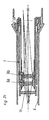
- Fig. 1 shows schematically a section through a telescopic sight according to the prior art. This has on the side facing the object when observing a hereinafter referred to as lens 4 lens arrangement and on the eye of the observer side facing a designated eyepiece 5 lens system. Between lens 4 and eyepiece 5 is the center tube 6. This often carries one or more Verstellürme 8, with which various well-known in the prior art adjustment functions can be performed. Within the central tube is located between the lens 4 and eyepiece 5, the reversing system 1. This is a well-known in the prior art optical system, which is used to erect the image generated by the lens 4. The reversing system 1 is usually arranged between the lens-side image plane 9 and the eyepiece-side image plane 10.
- the reversing system 1 often serves not only the erecting but also the enlargement of the intermediate image formed in the lens-side image plane 9.
- the magnifying optics is integrated into the reversing system 1. Magnifying optics and reversing system are thus executed in one component.
- two optical elements 3a and 3b are provided.
- these are achromats which are designed in a favorable manner for controlling the chromatic aberration as so-called cemented lenses, ie as glued-together lens arrangements. They have in the prior art as well as in reversal systems or remote optical devices according to the invention favorably refractive powers of + 20 dpt (diopters) to + 53 dpt, preferably from + 21 dpt to + 35 dpt, more preferably in the range between + 23 dpt and + 26 D, on.
- the optical elements 3a and 3b are movable along control grooves.
- the intermediate image designed by the objective 4 in the lens-side image plane 9 is imaged with a changing magnification and erected in the eyepiece-side image plane 10.
- the distance between the two image planes 9 and 10 does not change in the embodiment shown by the displacement of the optical elements 3a and 3b.
- Fig. 2a to 2c show the positions of the optical elements 3a and 3b at different magnifications.
- a simple magnification is achieved.
- reversing system 1 achieves a magnification of 2.5 times and in Fig. 2c shown position 4 times.
- the invention provides an optical beam deflection device 2.
- This is in an embodiment in the Fig. 3a to 3c shown and integrated here as an additional lens arrangement in the reversing system 1. That in the Fig. 3a to 3c shown reversing system 1 can, for example, instead of the reversing system 1 shown there in a scope according to Fig. 1 to get integrated.
- the optical beam deflection device 2 can just as well be arranged as a separate component, separate from the reversing system 1 in the remote-optical device.
- the inventive optical beam deflection device 2 it is also conceivable to realize the inventive optical beam deflection device 2 by appropriate design of the lenses 11, 3a and 3b. It is advantageously provided that the optical beam deflection device ensures the subjective field of view of at least 22 °, preferably between 22 ° and 24 °, with an enlarging optical system, preferably the reversing system, with at least five times, preferably at least six times, maximum magnification at all magnification levels.
- the optical beam deflection device 2 preferably two, glued together lenses 7, so Kittlinsen has.
- optical beam deflection device 2 it has proven to be advantageous to arrange the optical beam deflection device 2 on the side facing the eyepiece 5 side of the reversing system 1.
- the positioning on the side facing away from the eyepiece 5 side of the eyepiece-side image plane 10 is advantageous.
- a structurally particularly simple solution provides that the optical beam deflecting device 2 is fixed, that is to say not movable with respect to the central tube 6. However, in certain embodiments, it may also be necessary to make the optical beam deflecting device 2 movable, that is to say, as a rule, displaceable along the optical axis.
- the central tube 6 has hitherto in conventional riflescopes on an outer diameter between 30 mm and 35 mm. This, of course, calculated without any existing adjustment towers 8 or the like. This dimension of the central tube 6 is favorably maintained even with riflescopes according to the invention.
- the optical beam deflection device 2 has a refractive power between -20 dpt (diopters) and -40 dpt, preferably between -27 dpt and -37 dpt.
- a refractive power of -27.03 dpt is provided, whereby at all magnifications a subjective field of view of 23.5 ° is reached.
- the Fig. 3a to 3c again show the reversing system 1 according to the invention in three different positions of the provided for the enlargement and inversion of the image optical elements 3a and 3b.
- Fig. 3a For example, it is a simple magnification.
- Fig. 3b shows the positioning at 3.5x magnification and Fig. 3c at a sixfold magnification.
- the optical beam deflection device 2 provides by beam deflection for an enlargement of the subjective field of view. It can thereby be achieved according to the invention in all magnifications a subjective field of view of at least 22 ° or at the maximum magnification a total focal length less than or equal to 11 mm.
- the total focal length of the reversing system 1 according to the invention is due to the beam deflection 2 at the maximum magnification favorably between 11 mm and 7 mm, preferably between 10 mm and 8 mm. In the concrete embodiment mentioned, a total focal length of 8.264 mm was achieved in the maximum magnification.
- the size of the subjective field of view 2 ⁇ ' is determined by means of an angle measurement.
- the corresponding test setup for specimens with a real exit pupil is in Fig. 4 shown.
- an auxiliary telescope 28 is mounted on a turntable with an angle measuring device.
- an auxiliary telescope 28 with approximately three times the magnification, a diameter of the entrance pupil of approximately 3 mm and a bearing mark, such as a crosshair, should be used.
- green light with a wavelength of about 550 nm is used for the measurement.
- the measurement setup provides a sequence with a light source 21, a condenser 22, a filter 23, a diffuser 24, a remote optical device (specimen) 25 to be tested, a field stop 26 and an auxiliary telescope 28 at the position 27 of the exit pupil.
- the pivot axis of the auxiliary telescope 28 is located at the location of the exit pupil 27 and in the plane of the entrance pupil of the auxiliary telescope.
- the pivot axis intersects the optical axis of the specimen 25 and the auxiliary telescope 28 at right angles.
- the auxiliary telescope 28 placed on the field of view diaphragm 26 of the test piece 25 is to be pivoted, to bring its bearing mark successively on opposite edges of the field of view.
- the angular difference can be read on the scale of the angle measuring device of the swivel table (in degrees).
- the measurement of the total focal length of a reversal system is in accordance with DIN 58189 (issued in May 1996) and can be carried out with commercially available test equipment.
Landscapes
- Physics & Mathematics (AREA)
- Astronomy & Astrophysics (AREA)
- General Physics & Mathematics (AREA)
- Optics & Photonics (AREA)
- Telescopes (AREA)
- Lenses (AREA)
Abstract
Description
- Die vorliegende Erfindung betrifft eine fernoptische Einrichtung, insbesondere ein Fernrohr oder Zielfernrohr, mit einem Umkehrsystem und einer verstellbaren Vergrößerungsoptik mit einer mehr als vierfachen Vergrößerung.
- Wenn ein Gegenstand in großer Entfernung mit bloßem Auge betrachtet wird, so erscheint dieser unter einem kleinen Winkel. Sinn einer jeden fernoptischen Einrichtung ist es, diesen kleinen Winkel zu vergrößern. Die fernoptische Einrichtung sorgt also dafür, dass ein möglichst großer Erscheinungswinkel in das Auge des Betrachters gelangen kann. Zugleich sollte ein möglichst großer Geländeausschnitt überblickt werden können.
- Bei gattungsgemäßen zoombaren fernoptischen Einrichtungen mit verstellbarer Vergrößerung ist es besonders kritisch, über den gesamten Vergrößerungsbereich einen möglichst großen Geländeausschnitt überblicken zu können.
- Aufgabe der Erfindung ist es, gattungsgemäße fernoptische Einrichtungen diesbezüglich zu verbessern.
- Dies wird erfindungsgemäß durch ein Fernrohr oder Zielfernrohr erreicht, das ein Umkehrsystem enthält, in das eine verstellbare Vergrößerungsoptik integriert ist, wobei eine optische Strahlumlenkeinrichtung in das Umkehrsystems integriert ist, die durch eine zusätzliche Linsenanordnung gebildet ist, und wobei das Umkehrsystem in der maximalen Vergrößerung eine Gesamtbrennweite von höchstens 11 mm, zumindest für Licht mit einer Wellenlänge von etwa 550 nm, aufweist.
- Damit wird auch erreicht, dass bei allen Vergrößerungen ein subjektives Sehfeld der fernoptischen Einrichtung von mindestens 22°, vorzugsweise zwischen 22° und 24°, zumindest für Licht mit einer Wellenlänge von etwa 550 nm, gewährleistet ist.
- Mittels der optischen Strahlumlenkeinrichtung ist es nun auch bei niedrigen Vergrößerungen, insbesondere bei der niedrigsten Vergrößerung, der fernoptischen Einrichtung möglich, ein subjektives Sehfeld von mindestens 22° bereitzustellen. Dies war bisher nur bei größeren Vergrößerungen gattungsgemäßer fernoptischer Einrichtungen möglich. Der Betrachter sieht mit Hilfe der erfindungsgemäßen fernoptischen Einrichtung somit auch bei niedrigen Vergrößerungen einen größeren Geländeausschnitt, als dies der Stand der Technik bisher zuließ.
- Gemäß eines weiteren Aspektes der Erfindung ist vorgesehen, dass die Strahlumlenkeinrichtung in der maximalen Vergrößerung eine Gesamtbrennweite des Umkehrsystems zwischen 11 mm und 7 mm, vorzugsweise zwischen 10 mm und 8 mm, gewährleistet.
- Weitere Einzelheiten und Merkmale der Erfindung werden anhand der nachfolgend beschriebenen Figuren erläutert. Dabei zeigt:
- Fig. 1
- einen Längsschnitt durch ein Zielfernrohr gemäß des Standes der Technik;
- Fig. 2a bis 2c
- jeweils einen Schnitt durch ein Umkehrsystem gemäß des Standes der Technik;
- Fig. 3a bis 3c
- jeweils einen Schnitt durch ein Umkehrsystem für ein erfindungsgemäßes Ausführungsbeispiel eines Zielfernrohrs und
- Fig. 4
- einen schematisierten Messaufbau zur Bestimmung des subjektiven Sehfeldes.
-
Fig. 1 zeigt schematisch einen Schnitt durch ein Zielfernrohr gemäß des Standes der Technik. Dieses weist auf der beim Beobachten dem Objekt zugewandten Seite eine im Folgenden als Objektiv 4 bezeichnete Linsenanordnung und auf der dem Auge des Betrachters zugewandten Seite ein als Okular 5 bezeichnetes Linsensystem auf. Zwischen Objektiv 4 und Okular 5 befindet sich das Mittelrohr 6. Dieses trägt häufig einen oder mehrere Verstelltürme 8, mit denen verschiedene beim Stand der Technik bekannte Justierfunktionen durchgeführt werden können. Innerhalb des Mittelrohres befindet sich zwischen Objektiv 4 und Okular 5 das Umkehrsystem 1. Dies ist ein beim Stand der Technik bekanntes optisches System, das zur Aufrichtung des vom Objektiv 4 erzeugten Bildes dient. Das Umkehrsystem 1 ist in der Regel zwischen der objektivseitigen Bildebene 9 und der okularseitigen Bildebene 10 angeordnet. - Darüber hinaus dient das Umkehrsystem 1 häufig nicht nur dem Aufrichten sondern auch dem Vergrößern des in der objektivseitigen Bildebene 9 erzeugten Zwischenbildes. In dem Zielfernrohr gemäß
Fig. 1 ist die Vergrößerungsoptik in das Umkehrsystem 1 integriert. Vergrößerungsoptik und Umkehrsystem sind somit in einem Bauteil ausgeführt. - Zum Vergrößern und Aufrichten des Bildes sind zwei optische Elemente 3a und 3b vorgesehen. In der Regel handelt es sich hierbei um Achromaten, die in günstiger Weise zur Kontrolle der chromatischen Aberration als sogenannte Kittlinsen, also als zusammengeklebte Linsenanordnungen ausgeführt sind. Sie weisen beim Stand der Technik wie auch bei Umkehrsystemen bzw. fernoptischen Einrichtungen gemäß der Erfindung günstigerweise Brechkräfte von + 20 dpt (Dioptrien) bis + 53 dpt, vorzugsweise von + 21 dpt bis + 35 dpt, besonders bevorzugt im Bereich zwischen + 23 dpt und + 26 dpt, auf. Um die Vergrößerung des gezeigten Zielfernrohres verstellbar zu gestalten, sind die optischen Elemente 3a und 3b entlang von Steuernuten bewegbar. Durch Verschieben der optischen Elemente 3a und 3b wird das vom Objektiv 4 in der objektivseitigen Bildebene 9 entworfene Zwischenbild mit sich veränderndem Abbildungsmaßstab und aufgerichtet in der okularseitigen Bildebene 10 abgebildet. Der Abstand der beiden Bildebenen 9 und 10 ändert sich im gezeigten Ausührungsbeispiel durch das Verschieben der optischen Elemente 3a und 3b nicht. Beim Stand der Technik ist es darüber hinaus auch bekannt, zusätzlich noch eine Feldlinse 11 vorzusehen. Diese hilft, das vom Objektiv 4 kommende Strahlenbündel eines am Sehfeldrand liegenden Objektpunktes durch den engen Kanal des Mittelrohres 6 bzw. Umkehrsystems 1 hindurchzuleiten.
- Die Veränderung des Abbildungsmaßstabes durch Bewegung der optischen Elemente 3a und 3b entlang von hier nicht weiter im Detail dargestellten Steuernuten ist beim Stand der Technik bekannt. Die
Fig. 2a bis 2c zeigen die Stellungen der optischen Elemente 3a und 3b bei verschiedenen Vergrößerungen. In der inFig. 2a gezeigten Stellung wird zum Beispiel eine einfache Vergrößerung erreicht. In der Stellung gemäßFig. 2b erzielt das Umkehrsystem 1 eine Vergrößerung um das 2,5-fache und in der inFig. 2c gezeigten Stellung um das 4-fache. - Um nun ein subjektives Sehfeld von mindestens 22° b ei einer fernoptischen Einrichtung mit einer maximalen Vergrößerung bzw. einem maximalen Zoom größer vierfach auch bei niedrigen Vergrößerungen gewährleisten zu können, sieht die Erfindung eine optische Strahlumlenkeinrichtung 2 vor. Diese ist in einem Ausführungsbeispiel in den
Fig. 3a bis 3c gezeigt und hier als zusätzliche Linsenanordnung in das Umkehrsystem 1 integriert. Das in denFig. 3a bis 3c gezeigte erfindungsgemäße Umkehrsystem 1 kann zum Beispiel an Stelle des dort gezeigten Umkehrsystems 1 in ein Zielfernrohr gemäßFig. 1 integriert werden. - Die optische Strahlumlenkeinrichtung 2 kann aber genauso gut als separates Bauteil, getrennt vom Umkehrsystem 1 in der fernoptischen Einrichtung angeordnet sein. Andererseits ist es aber auch denkbar die erfindungsgemäße optische Strahlumlenkeinrichtung 2 durch entsprechende Ausbildung der Linsen 11, 3a und 3b zu realisieren. Günstigerweise ist vorgesehen, dass die optische Strahlumlenkeinrichtung das subjektive Sehfeld von mindestens 22°, vorzugsweise zwischen 22° und 24°, bei einer Vergrößerungsoptik, vorzugsweise des Umkehrsystems, mit einer mindestens fünffachen, vorzugsweise bei einer mindestens sechsfachen, maximalen Vergrößerung bei allen Vergrößerungsstufen gewährleistet. Zur besseren Kontrolle der chromatischen Aberration erweist es sich als sinnvoll, dass die optische Strahlumlenkeinrichtung 2, vorzugsweise zwei, miteinander verklebte Linsen 7, also Kittlinsen, aufweist. Es wäre aber auch denkbar, die optische Strahlumlenkeinrichtung 2 als Einzellinse auszubilden.
- Es hat sich als günstig herausgestellt, die optische Strahlumlenkeinrichtung 2 auf der zum Okular 5 weisenden Seite des Umkehrsystems 1 anzuordnen. Vorteilhaft ist dabei die Positionierung auf der vom Okular 5 wegweisenden Seite der okularseitigen Bildebene 10.
- Eine konstruktiv besonders einfache Lösung sieht vor, dass die optische Strahlumlenkeinrichtung 2 fix, also nicht bewegbar bezüglich des Mittelrohres 6, angeordnet ist. Es kann sich in gewissen Ausführungsformen aber auch als notwendig erweisen, die optische Strahlumlenkeinrichtung 2 bewegbar, also in der Regel entlang der optischen Achse verschiebbar, auszugestalten.
- Das Mittelrohr 6 weist bisher bei gängigen Zielfernrohren einen Außendurchmesser zwischen 30 mm und 35 mm auf. Dies natürlich gerechnet ohne etwaig vorhandene Verstelltürme 8 oder dergleichen. Diese Abmessung des Mittelrohres 6 wird günstigerweise auch bei erfindungsgemäßen Zielfernrohren beibehalten.
- In der Regel ist es günstig, dass die optische Strahlumlenkeinrichtung 2 eine Brechkraft zwischen -20 dpt (Dioptrien) und -40 dpt, vorzugsweise zwischen -27 dpt und -37 dpt, aufweist. In einem konkreten Beispiel ist eine Brechkraft von -27,03 dpt vorgesehen, wobei bei allen Vergrößerungen ein subjektives Sehfeld von 23,5° erreicht wird.
- Die
Fig. 3a bis 3c zeigen das erfindungsgemäße Umkehrsystem 1 wiederum in drei verschiedenen Positionen der für die Vergrößerung und Umkehrung des Bildes vorgesehenen optischen Elemente 3a und 3b. In der Stellung inFig. 3a handelt es sich zum Beispiel um eine einfache Vergrößerung.Fig. 3b zeigt die Positionierung bei einer 3,5-fachen Vergrößerung undFig. 3c bei einer sechsfachen Vergrößerung. Die optische Strahlumlenkeinrichtung 2 sorgt durch Strahlumlenkung für eine Vergrößerung des subjektiven Sehfeldes. Es kann hierdurch erfindungsgemäß bei allen Vergrößerungen ein subjektives Sehfeld von mindestens 22° bzw. bei der maximalen Vergrößerung eine Gesamtbrennweite kleiner gleich 11 mm erreicht werden. Die Gesamtbrennweite des erfindungsgemäßen Umkehrsystems 1 liegt auf Grund der Strahlumlenkeinrichtung 2 bei der maximalen Vergrößerung günstigerweise zwischen 11 mm und 7 mm, vorzugsweise zwischen 10 mm und 8 mm. Im erwähnten konkreten Ausführungsbeispiel wurde eine Gesamtbrennweite von 8,264 mm in der maximalen Vergrößerung erreicht. - Die Größe des subjektiven Sehfeldes 2 ω' wird mittels einer Winkelmessung bestimmt. Der entsprechende Messaufbau für Prüflinge mit einer reellen Austrittspupille ist in
Fig. 4 gezeigt. Auf der Okularseite des Prüflings 25 wird ein Hilfsfernrohr 28 auf einem Drehtisch mit einer Winkelmesseinrichtung montiert. Es sollte dabei ein Hilfsfernrohr 28 mit etwa dreifacher Vergrößerung, einem Durchmesser der Eintrittspupille von etwa 3 mm und einer Peilmarke, wie zum Beispiel einem Fadenkreuz, verwendet werden. Zur Vermeidung von Farbsäumen im Bild wird zur Messung grünes Licht mit einer Wellenlänge von etwa 550 nm verwendet. Der Messaufbau sieht eine Abfolge mit einer Lichtquelle 21, einem Kondensor 22, einem Filter 23, einer Streuscheibe 24, einer zu prüfenden fernoptischen Einrichtung (Prüfling) 25, einer Sehfeldblende 26 und einem Hilfsfernrohr 28 auf der Position 27 der Austrittspupille vor. Zur Durchführung der Messung liegt die Schwenkachse des Hilfsfernrohres 28 am Ort der Austrittspupille 27 und in der Ebene der Eintrittspupille des Hilfsfernrohrs. Die Schwenkachse schneidet die optische Achse des Prüflings 25 und die des Hilfsfernrohres 28 rechtwinklig. Das auf die Sehfeldblende 26 des Prüflings 25 scharf gestellte Hilfsfernrohr 28 ist zu schwenken, um dessen Peilmarke nacheinander auf einander gegenüberliegende Ränder des Sehfeldes zu bringen. Die Winkeldifferenz ist an der Skala der Winkelmesseinrichtung des Schwenktisches (in Grad) abzulesen. - Die Messung der Gesamtbrennweite eines Umkehrsystems erfolgt gemäß DIN 58189 (herausgegeben im Mai 1996) und kann mit handelsüblichen Prüfgeräte durchgeführt werden.
Claims (10)
- Fernrohr oder Zielfernrohr mit einem Mittelrohr (6), das zwischen einem Objektiv (4) und einem Okular (5) angeordnet ist, wobei das Mittelrohr (6) einen maximalen Außendurchmesser von 35 mm aufweist,- und wobei das Mittelrohr (6) ein Umkehrsystem (1) enthält, in das eine verstellbare Vergrößerungsoptik integriert ist und die in einem Bauteil ausgeführt und durch eine Linsenanordnung mit zumindest zwei relativ zueinander verschiebbaren optischen Elementen (3a, 3b) gebildet ist,- wobei durch das Verschieben zumindest der optischen Elemente (3a, 3b) des Umkehrsystems (1) ein von dem Objektiv (4) in einer objektivseitigen Bildebene (9) entworfenes Zwischenbild mit einem veränderbaren Abbildungsmaßstab und aufgerichtet mit einem maximalen Zoom größer vierfach, in einer okularseitigen Bildebene (10) abgebildet ist- und wobei eine durch eine zusätzliche Linsenanordnung gebildete optische Strahlumlenkeinrichtung (2) auf der dem Okular (5) zugewandten Seite des Umkehrsystems (1) angeordnet ist,dadurch gekennzeichnet, dass das Umkehrsystem (1) in der maximalen Vergrößerung eine Gesamtbrennweite von höchstens 11 mm, zumindest für Licht mit einer Wellenlänge von etwa 550 nm, aufweist.
- Fernrohr oder Zielfernrohr nach Anspruch 1, dadurch gekennzeichnet, dass das Umkehrsystem (1) in der maximalen Vergrößerung eine Gesamtbrennweite zwischen 11 mm und 7 mm aufweist.
- Fernrohr oder Zielfernrohr nach Anspruch 2, dadurch gekennzeichnet, dass das Umkehrsystem (1) in der maximalen Vergrößerung eine Gesamtbrennweite zwischen 10 mm und 8 mm aufweist.
- Fernrohr oder Zielfernrohr nach einem der vorhergehenden Ansprüche, dadurch gekennzeichnet, dass das Umkehrsystem (1) einen mindestens fünffachen Zoom, vorzugsweise einen mindestens sechsfachen Zoom, aufweist.
- Fernrohr oder Zielfernrohr nach einem der vorhergehenden Ansprüche, dadurch gekennzeichnet, dass die optische Strahlumlenkeinrichtung (2) auf der vom Okular (5) wegweisenden Seite einer okularseitigen Bildebene (10) der fernoptischen Einrichtung angeordnet ist.
- Fernrohr oder Zielfernrohr nach einem der vorhergehenden Ansprüche, dadurch gekennzeichnet, dass die optische Strahlumlenkeinrichtung (2), vorzugsweise zwei, miteinander verklebte Linsen (7) aufweist.
- Fernrohr oder Zielfernrohr nach einem der vorhergehenden Ansprüche, dadurch gekennzeichnet, dass die optische Strahlumlenkeinrichtung (2) eine negative Brechkraft zwischen -20 dpt (Dioptrien) und -40 dpt aufweist.
- Fernrohr oder Zielfernrohr nach Anspruch 7, dadurch gekennzeichnet, dass die optische Strahlumlenkeinrichtung (2) eine Brechkraft zwischen -27 dpt und -37 dpt aufweist.
- Fernrohr oder Zielfernrohr nach einem der vorhergehenden Ansprüche 1 bis 7, dadurch gekennzeichnet, dass die optische Strahlumlenkeinrichtung (2) auf der zum Okular (5) weisenden Seite des Umkehrsystems (1) fix angeordnet ist.
- Fernrohr oder Zielfernrohr nach einem der vorhergehenden Ansprüche, dadurch gekennzeichnet, dass das Umkehrsystem (1) zwischen einer objektivseitigen Bildebene (9) und einer okularseitigen Bildebene (10) angeordnet ist, wobei die objektivseitige Bildebene (9) zwischen dem Objektiv (4) und der dem Objektiv (4) zugewandten Seite des Umkehrsystems (1) liegt, und die okularseitige Bildebene (10) zwischen dem Okular (5) und der dem Okular (5) zugewandten Seite des Umkehrsystems (1) liegt.
Priority Applications (1)
| Application Number | Priority Date | Filing Date | Title |
|---|---|---|---|
| EP19187590.5A EP3598196B1 (de) | 2005-07-20 | 2006-04-08 | Fernoptische einrichtung mit grossem sehfeld und hoher vergrösserung |
Applications Claiming Priority (2)
| Application Number | Priority Date | Filing Date | Title |
|---|---|---|---|
| AT0122005A AT502229B1 (de) | 2005-07-20 | 2005-07-20 | Fernoptische einrichtung |
| EP06007466.3A EP1746451B2 (de) | 2005-07-20 | 2006-04-08 | Fernrohr mit grossem Sehfeld und variabler Vergrösserung |
Related Parent Applications (3)
| Application Number | Title | Priority Date | Filing Date |
|---|---|---|---|
| EP06007466.3A Division EP1746451B2 (de) | 2005-07-20 | 2006-04-08 | Fernrohr mit grossem Sehfeld und variabler Vergrösserung |
| EP06007466.3A Division-Into EP1746451B2 (de) | 2005-07-20 | 2006-04-08 | Fernrohr mit grossem Sehfeld und variabler Vergrösserung |
| EP06007466.3 Division | 2006-04-08 |
Related Child Applications (2)
| Application Number | Title | Priority Date | Filing Date |
|---|---|---|---|
| EP19187590.5A Division-Into EP3598196B1 (de) | 2005-07-20 | 2006-04-08 | Fernoptische einrichtung mit grossem sehfeld und hoher vergrösserung |
| EP19187590.5A Division EP3598196B1 (de) | 2005-07-20 | 2006-04-08 | Fernoptische einrichtung mit grossem sehfeld und hoher vergrösserung |
Publications (2)
| Publication Number | Publication Date |
|---|---|
| EP2211222A1 true EP2211222A1 (de) | 2010-07-28 |
| EP2211222B1 EP2211222B1 (de) | 2023-10-18 |
Family
ID=37110360
Family Applications (3)
| Application Number | Title | Priority Date | Filing Date |
|---|---|---|---|
| EP19187590.5A Expired - Lifetime EP3598196B1 (de) | 2005-07-20 | 2006-04-08 | Fernoptische einrichtung mit grossem sehfeld und hoher vergrösserung |
| EP06007466.3A Expired - Lifetime EP1746451B2 (de) | 2005-07-20 | 2006-04-08 | Fernrohr mit grossem Sehfeld und variabler Vergrösserung |
| EP10001987.6A Expired - Lifetime EP2211222B1 (de) | 2005-07-20 | 2006-04-08 | Fernoptische Einrichtung mit grossem Sehfeld und hoher Vergrösserung |
Family Applications Before (2)
| Application Number | Title | Priority Date | Filing Date |
|---|---|---|---|
| EP19187590.5A Expired - Lifetime EP3598196B1 (de) | 2005-07-20 | 2006-04-08 | Fernoptische einrichtung mit grossem sehfeld und hoher vergrösserung |
| EP06007466.3A Expired - Lifetime EP1746451B2 (de) | 2005-07-20 | 2006-04-08 | Fernrohr mit grossem Sehfeld und variabler Vergrösserung |
Country Status (5)
| Country | Link |
|---|---|
| US (6) | US7742228B2 (de) |
| EP (3) | EP3598196B1 (de) |
| AT (2) | AT502229B1 (de) |
| DE (3) | DE202006020736U1 (de) |
| ES (1) | ES2347169T3 (de) |
Families Citing this family (13)
| Publication number | Priority date | Publication date | Assignee | Title |
|---|---|---|---|---|
| DE102011000685B3 (de) | 2011-02-11 | 2012-08-09 | Schmidt & Bender Gmbh & Co. Kg | Zielfernrohr mit Korrekturfeldlinse |
| DE102011001044A1 (de) | 2011-03-02 | 2012-09-06 | Schmidt & Bender Gmbh & Co. Kg | Zielfernrohr mit vergrößerter Austrittspupille |
| DE102012205601A1 (de) | 2012-04-04 | 2013-10-10 | Carl Zeiss Meditec Ag | Optisches System, insbesondere ein Zielfernrohr |
| AT513009B1 (de) * | 2012-06-11 | 2021-02-15 | Swarovski Optik Kg | Objektiv für ein Bildaufzeichnungsgerät |
| KR101541904B1 (ko) * | 2014-10-20 | 2015-08-06 | 양원종 | 시력보정용 광학기기 |
| AT518376B1 (de) | 2016-03-02 | 2017-12-15 | Swarovski-Optik Kg | Umkehrsystem für ein Zielfernrohr |
| US10405036B2 (en) * | 2016-06-24 | 2019-09-03 | The Nielsen Company (Us), Llc | Invertible metering apparatus and related methods |
| AT518634B1 (de) | 2016-12-01 | 2017-12-15 | Kahles Ges M B H | Verstellturm für eine fernoptische Einrichtung |
| AT518653B1 (de) | 2016-12-01 | 2017-12-15 | Kahles Ges M B H | Verstellturm für eine fernoptische Einrichtung |
| DE102017100652B4 (de) * | 2017-01-13 | 2022-09-29 | Schmidt & Bender Gmbh & Co. Kg | Umkehrsystem für Zielfernrohre und Zielfernrohr mit einem solchen |
| CN106908941B (zh) * | 2017-05-04 | 2022-06-21 | 成都东旺光电有限公司 | 变倍瞄准镜的转像组及变倍瞄准镜 |
| DE102020134017A1 (de) | 2020-08-13 | 2022-02-17 | Carl Zeiss Ag | Optisches System |
| DE102022102213B4 (de) | 2022-01-31 | 2023-08-24 | Carl Zeiss Ag | Optisches System |
Citations (4)
| Publication number | Priority date | Publication date | Assignee | Title |
|---|---|---|---|---|
| GB191321621A (en) * | 1912-10-04 | 1913-12-18 | Zeiss Carl | Improvements in Terrestrial Telescopes of Variable Power. |
| US3045545A (en) * | 1960-11-10 | 1962-07-24 | Bausch & Lomb | Optical system for sighting instruments |
| US4172634A (en) * | 1977-09-28 | 1979-10-30 | W. R. Weaver Company | Cam follower for variable power scopes |
| WO2006081411A2 (en) * | 2005-01-26 | 2006-08-03 | Meade Instruments Corporation | Scope with improved magnification system |
Family Cites Families (40)
| Publication number | Priority date | Publication date | Assignee | Title |
|---|---|---|---|---|
| DE252732C (de) | ||||
| DE198489C (de) | ||||
| AT31994B (de) † | 1906-10-27 | 1908-02-25 | Optische Anstalt Goerz Ag | Fernrohr mit verschiebbarem Umkehrsystem. |
| GB191121621A (en) * | 1911-07-12 | 1912-07-25 | Friedrich Pels-Leusden | Improvements in Pince-nez Eyeglasses. |
| AT59149B (de) † | 1911-08-25 | 1913-05-10 | Optische Anstalt Goerz Ag | Fernrohr mit veränderlicher Vergrößerung. |
| GB191419446A (en) | 1914-09-04 | 1915-10-04 | British Thomson Houston Co Ltd | Protecting Hot-cathode Vacuum Tubes or other Devices havingsimilar characteristics from Overload. |
| US1464655A (en) * | 1921-08-09 | 1923-08-14 | Firm Optische Anstalt C P Goer | Sighting telescope with changeable magnifying power |
| GB303787A (en) * | 1928-01-09 | 1929-07-11 | Optique Sa Des Anciens Ets Lis | An inverting lens system for telescopes |
| US2207124A (en) † | 1938-03-08 | 1940-07-09 | Frederick L G Kollmorgen | Rifle-sighting telescope |
| US2479792A (en) * | 1948-05-15 | 1949-08-23 | Bausch & Lomb | Optical system for variable power telescopes |
| GB690278A (en) * | 1949-06-29 | 1953-04-15 | Emel Ets | Improvements in optical view finders |
| DE975486C (de) † | 1949-11-01 | 1961-12-07 | Leitz Ernst Gmbh | Fernrohr-Okular mit weitabstehender Austrittspupille und grossem Gesichtsfeld |
| US3161716A (en) † | 1962-02-19 | 1964-12-15 | Redfield Gun Sight Company | Variable power riflescope with tilting reticle and erector tube |
| US3384434A (en) † | 1965-04-02 | 1968-05-21 | Army Usa | Wide angle eyepiece with large eye relief |
| FR2044465A5 (de) | 1969-05-21 | 1971-02-19 | Clave Serge | |
| US3967876A (en) * | 1973-07-20 | 1976-07-06 | W. R. Weaver Company | Telescopic gun sight |
| US3902251A (en) † | 1974-07-17 | 1975-09-02 | Weaver Co W R | Adjustable reticle for telescopic rifle sights |
| US3918791A (en) * | 1974-10-18 | 1975-11-11 | Leupold & Stevens Inc | Flat field variable power rifle scope |
| JPS54133355A (en) * | 1978-04-07 | 1979-10-17 | Nippon Chemical Ind | Erect type zoom telephoto optical system |
| US4286844A (en) † | 1979-11-07 | 1981-09-01 | Albert Nagler | Ultrawide angle flat field eyepiece |
| US4497548A (en) † | 1980-12-05 | 1985-02-05 | Burris Company | Variable-power riflescope with range-compensating reticle and a field stop diaphram centered off the optical axis |
| US4408842A (en) † | 1981-10-08 | 1983-10-11 | Leupold & Stevens, Inc. | Telescopic sight having lens holder tube with half socket pivot mount |
| US4530812A (en) | 1982-01-15 | 1985-07-23 | Fdx Patents Holding Company, N.V. | Composite coils for toroidal field coils and method of using same |
| ATE31994T1 (de) | 1982-01-15 | 1988-01-15 | Fdx Patents Holding Co | Segmentierte spulen fuer torusfoermige magnetfeldspulen und anwendungsmethode. |
| DE3580986D1 (de) | 1984-03-26 | 1991-01-31 | Keith Harrison | Golfschlaguebungsgeraet. |
| DD269694A1 (de) * | 1987-12-29 | 1989-07-05 | Zeiss Jena Veb Carl | Weitwinkelokular |
| DE3828413A1 (de) † | 1988-08-20 | 1990-02-22 | Harald Mauri | Optisches system eines kurzbrennweitigen refraktors |
| DE3838413A1 (de) | 1988-11-12 | 1990-05-17 | Mania Gmbh | Adapter fuer elektronische pruefvorrichtungen fuer leiterplatten und dergl. |
| US5671088A (en) | 1992-06-03 | 1997-09-23 | Leupold & Stevens, Inc. | Variable optical aiming devices |
| US5371626A (en) | 1993-03-09 | 1994-12-06 | Benopcon, Inc. | Wide angle binocular system with variable power capability |
| US5727236A (en) * | 1994-06-30 | 1998-03-10 | Frazier; James A. | Wide angle, deep field, close focusing optical system |
| US5548439A (en) * | 1994-12-27 | 1996-08-20 | Hughes Aircraft Company | Three field of view refractive infrared telescope with fixed medium filed of view |
| JP3051461U (ja) * | 1997-11-21 | 1998-08-25 | 鎌倉光機株式会社 | 広視界変倍双眼鏡 |
| JP3524408B2 (ja) * | 1998-01-06 | 2004-05-10 | キヤノン株式会社 | 観察光学系及びそれを有する光学機器 |
| JPH11328789A (ja) † | 1998-05-12 | 1999-11-30 | Sony Corp | 記録再生媒体の排出機構 |
| JPH11326789A (ja) | 1998-05-18 | 1999-11-26 | Nikon Corp | 接眼レンズ |
| JP3510809B2 (ja) * | 1999-01-22 | 2004-03-29 | ペンタックス株式会社 | 眼視望遠ズームレンズ系 |
| US6367189B1 (en) * | 2000-04-05 | 2002-04-09 | David Richard Clay | Non-protruding aiming apparatus for handguns |
| US20060168871A1 (en) * | 2001-04-05 | 2006-08-03 | Thomas Wagner | Sighting telescope |
| US7207487B2 (en) | 2004-07-26 | 2007-04-24 | Swingvote, Inc. | Method and system for electronic solicitation of votes affecting corporate affairs |
-
2005
- 2005-07-20 AT AT0122005A patent/AT502229B1/de not_active IP Right Cessation
-
2006
- 2006-04-08 AT AT06007466T patent/ATE470882T1/de active
- 2006-04-08 EP EP19187590.5A patent/EP3598196B1/de not_active Expired - Lifetime
- 2006-04-08 EP EP06007466.3A patent/EP1746451B2/de not_active Expired - Lifetime
- 2006-04-08 EP EP10001987.6A patent/EP2211222B1/de not_active Expired - Lifetime
- 2006-04-08 DE DE202006020736U patent/DE202006020736U1/de not_active Expired - Lifetime
- 2006-04-08 DE DE202006021185U patent/DE202006021185U1/de not_active Expired - Lifetime
- 2006-04-08 ES ES06007466T patent/ES2347169T3/es not_active Expired - Lifetime
- 2006-04-08 DE DE502006007146T patent/DE502006007146D1/de not_active Expired - Lifetime
- 2006-06-16 US US11/453,983 patent/US7742228B2/en active Active
-
2010
- 2010-06-03 US US12/793,073 patent/US8054544B2/en not_active Expired - Lifetime
-
2011
- 2011-09-16 US US13/234,705 patent/US8786947B2/en not_active Expired - Lifetime
-
2014
- 2014-06-16 US US14/305,849 patent/US9529185B2/en not_active Expired - Lifetime
-
2016
- 2016-11-14 US US15/350,397 patent/US10620422B2/en not_active Expired - Lifetime
-
2020
- 2020-02-21 US US16/797,558 patent/US20200201020A1/en not_active Abandoned
Patent Citations (4)
| Publication number | Priority date | Publication date | Assignee | Title |
|---|---|---|---|---|
| GB191321621A (en) * | 1912-10-04 | 1913-12-18 | Zeiss Carl | Improvements in Terrestrial Telescopes of Variable Power. |
| US3045545A (en) * | 1960-11-10 | 1962-07-24 | Bausch & Lomb | Optical system for sighting instruments |
| US4172634A (en) * | 1977-09-28 | 1979-10-30 | W. R. Weaver Company | Cam follower for variable power scopes |
| WO2006081411A2 (en) * | 2005-01-26 | 2006-08-03 | Meade Instruments Corporation | Scope with improved magnification system |
Non-Patent Citations (1)
| Title |
|---|
| ALBERT KÖNIG, HORST KÖHLER: "Die Fernrohre und Entfernungsmesser", 1 January 1959, SPRINGER VERLAG, Berlin, XP002582811 * |
Also Published As
| Publication number | Publication date |
|---|---|
| US8054544B2 (en) | 2011-11-08 |
| US9529185B2 (en) | 2016-12-27 |
| DE202006020736U1 (de) | 2009-12-03 |
| US10620422B2 (en) | 2020-04-14 |
| EP2211222B1 (de) | 2023-10-18 |
| DE202006021185U1 (de) | 2013-06-06 |
| US20070019289A1 (en) | 2007-01-25 |
| US20200201020A1 (en) | 2020-06-25 |
| AT502229B1 (de) | 2007-05-15 |
| EP1746451A2 (de) | 2007-01-24 |
| US20170059846A1 (en) | 2017-03-02 |
| US20100238542A1 (en) | 2010-09-23 |
| US20120008198A1 (en) | 2012-01-12 |
| EP1746451B1 (de) | 2010-06-09 |
| DE502006007146D1 (de) | 2010-07-22 |
| AT502229A1 (de) | 2007-02-15 |
| ATE470882T1 (de) | 2010-06-15 |
| US8786947B2 (en) | 2014-07-22 |
| EP3598196A1 (de) | 2020-01-22 |
| ES2347169T3 (es) | 2010-10-26 |
| US20140293413A1 (en) | 2014-10-02 |
| US7742228B2 (en) | 2010-06-22 |
| EP3598196B1 (de) | 2023-10-18 |
| EP1746451A3 (de) | 2007-07-11 |
| EP1746451B2 (de) | 2019-10-09 |
Similar Documents
| Publication | Publication Date | Title |
|---|---|---|
| DE102014108811B3 (de) | Stereomikroskop mit einem Hauptbeobachterstrahlengang und einem Mitbeobachterstrahlengang | |
| DE10222041A1 (de) | Afokaler Zoom zur Verwendung in Mikroskopen | |
| DE102017108595B3 (de) | Immersionsobjektiv für ein Mikroskop | |
| DE3507458A1 (de) | Stereomikroskop fuer operationen | |
| AT502229B1 (de) | Fernoptische einrichtung | |
| WO1987006714A1 (fr) | Element optique et dispositf l'utilisant | |
| EP4471490B1 (de) | Beobachtungsfernrohr | |
| DE102004051357B4 (de) | Immersions-Mikroskopobjektiv | |
| DE102017108593B4 (de) | Korrektionsobjektiv für ein Mikroskop, Immersionsobjektiv und Mikroskop | |
| DE102004003139A1 (de) | Polarausrichtungsteil variabler Brennweite | |
| EP3958024A1 (de) | Autofokussierbares mikroskopobjektiv mit flüssiglinse | |
| EP2495599B1 (de) | Zielfernrohr mit vergrößerter Austrittspupille | |
| EP3168671B1 (de) | Beleuchtungsanordnung | |
| DE102007015896A1 (de) | Teleoptik für den infraroten Spektalbereich | |
| DE102011000685B3 (de) | Zielfernrohr mit Korrekturfeldlinse | |
| AT508626A1 (de) | Fernoptische einrichtung | |
| DE102008013702A1 (de) | Optisches System | |
| DE102014108596B3 (de) | Objektiv und optisches Gerät | |
| DE20207780U1 (de) | Afokaler Zoom zur Verwendung in Mikroskopen | |
| DE3784964T2 (de) | Optische vorrichtung. | |
| DE102004048844A1 (de) | Optisches System | |
| EP2605055A1 (de) | Fernglas zur Abbildung eines Objekts | |
| DE1199018B (de) | Seitenmikroskop fuer binokulare Stereo-mikroskope | |
| DE102006026419A1 (de) | Fernrohrokular mit weitabstehender Austrittspupille | |
| DE2648857A1 (de) | Zeichnungs-zusatzgeraet fuer ein mikroskop |
Legal Events
| Date | Code | Title | Description |
|---|---|---|---|
| PUAI | Public reference made under article 153(3) epc to a published international application that has entered the european phase |
Free format text: ORIGINAL CODE: 0009012 |
|
| AC | Divisional application: reference to earlier application |
Ref document number: 1746451 Country of ref document: EP Kind code of ref document: P |
|
| AK | Designated contracting states |
Kind code of ref document: A1 Designated state(s): AT BE BG CH CY CZ DE DK EE ES FI FR GB GR HU IE IS IT LI LT LU LV MC NL PL PT RO SE SI SK TR |
|
| AX | Request for extension of the european patent |
Extension state: AL BA HR MK YU |
|
| 17P | Request for examination filed |
Effective date: 20110128 |
|
| 17Q | First examination report despatched |
Effective date: 20160302 |
|
| STAA | Information on the status of an ep patent application or granted ep patent |
Free format text: STATUS: EXAMINATION IS IN PROGRESS |
|
| RAP1 | Party data changed (applicant data changed or rights of an application transferred) |
Owner name: SWAROVSKI-OPTIK KG. |
|
| RAP1 | Party data changed (applicant data changed or rights of an application transferred) |
Owner name: SWAROVSKI-OPTIK AG & CO KG. |
|
| GRAP | Despatch of communication of intention to grant a patent |
Free format text: ORIGINAL CODE: EPIDOSNIGR1 |
|
| STAA | Information on the status of an ep patent application or granted ep patent |
Free format text: STATUS: GRANT OF PATENT IS INTENDED |
|
| INTG | Intention to grant announced |
Effective date: 20230607 |
|
| P01 | Opt-out of the competence of the unified patent court (upc) registered |
Effective date: 20230525 |
|
| GRAS | Grant fee paid |
Free format text: ORIGINAL CODE: EPIDOSNIGR3 |
|
| GRAA | (expected) grant |
Free format text: ORIGINAL CODE: 0009210 |
|
| STAA | Information on the status of an ep patent application or granted ep patent |
Free format text: STATUS: THE PATENT HAS BEEN GRANTED |
|
| AC | Divisional application: reference to earlier application |
Ref document number: 1746451 Country of ref document: EP Kind code of ref document: P |
|
| AK | Designated contracting states |
Kind code of ref document: B1 Designated state(s): AT BE BG CH CY CZ DE DK EE ES FI FR GB GR HU IE IS IT LI LT LU LV MC NL PL PT RO SE SI SK TR |
|
| REG | Reference to a national code |
Ref country code: GB Ref legal event code: FG4D Free format text: NOT ENGLISH |
|
| REG | Reference to a national code |
Ref country code: CH Ref legal event code: EP |
|
| REG | Reference to a national code |
Ref country code: IE Ref legal event code: FG4D Free format text: LANGUAGE OF EP DOCUMENT: GERMAN |
|
| REG | Reference to a national code |
Ref country code: DE Ref legal event code: R096 Ref document number: 502006016498 Country of ref document: DE |
|
| REG | Reference to a national code |
Ref country code: LT Ref legal event code: MG9D |
|
| REG | Reference to a national code |
Ref country code: NL Ref legal event code: MP Effective date: 20231018 |
|
| PG25 | Lapsed in a contracting state [announced via postgrant information from national office to epo] |
Ref country code: NL Free format text: LAPSE BECAUSE OF FAILURE TO SUBMIT A TRANSLATION OF THE DESCRIPTION OR TO PAY THE FEE WITHIN THE PRESCRIBED TIME-LIMIT Effective date: 20231018 |
|
| PG25 | Lapsed in a contracting state [announced via postgrant information from national office to epo] |
Ref country code: GR Free format text: LAPSE BECAUSE OF FAILURE TO SUBMIT A TRANSLATION OF THE DESCRIPTION OR TO PAY THE FEE WITHIN THE PRESCRIBED TIME-LIMIT Effective date: 20240119 |
|
| PG25 | Lapsed in a contracting state [announced via postgrant information from national office to epo] |
Ref country code: IS Free format text: LAPSE BECAUSE OF FAILURE TO SUBMIT A TRANSLATION OF THE DESCRIPTION OR TO PAY THE FEE WITHIN THE PRESCRIBED TIME-LIMIT Effective date: 20240218 |
|
| PG25 | Lapsed in a contracting state [announced via postgrant information from national office to epo] |
Ref country code: LT Free format text: LAPSE BECAUSE OF FAILURE TO SUBMIT A TRANSLATION OF THE DESCRIPTION OR TO PAY THE FEE WITHIN THE PRESCRIBED TIME-LIMIT Effective date: 20231018 |
|
| PG25 | Lapsed in a contracting state [announced via postgrant information from national office to epo] |
Ref country code: ES Free format text: LAPSE BECAUSE OF FAILURE TO SUBMIT A TRANSLATION OF THE DESCRIPTION OR TO PAY THE FEE WITHIN THE PRESCRIBED TIME-LIMIT Effective date: 20231018 |
|
| PG25 | Lapsed in a contracting state [announced via postgrant information from national office to epo] |
Ref country code: LT Free format text: LAPSE BECAUSE OF FAILURE TO SUBMIT A TRANSLATION OF THE DESCRIPTION OR TO PAY THE FEE WITHIN THE PRESCRIBED TIME-LIMIT Effective date: 20231018 Ref country code: IS Free format text: LAPSE BECAUSE OF FAILURE TO SUBMIT A TRANSLATION OF THE DESCRIPTION OR TO PAY THE FEE WITHIN THE PRESCRIBED TIME-LIMIT Effective date: 20240218 Ref country code: GR Free format text: LAPSE BECAUSE OF FAILURE TO SUBMIT A TRANSLATION OF THE DESCRIPTION OR TO PAY THE FEE WITHIN THE PRESCRIBED TIME-LIMIT Effective date: 20240119 Ref country code: ES Free format text: LAPSE BECAUSE OF FAILURE TO SUBMIT A TRANSLATION OF THE DESCRIPTION OR TO PAY THE FEE WITHIN THE PRESCRIBED TIME-LIMIT Effective date: 20231018 Ref country code: BG Free format text: LAPSE BECAUSE OF FAILURE TO SUBMIT A TRANSLATION OF THE DESCRIPTION OR TO PAY THE FEE WITHIN THE PRESCRIBED TIME-LIMIT Effective date: 20240118 Ref country code: PT Free format text: LAPSE BECAUSE OF FAILURE TO SUBMIT A TRANSLATION OF THE DESCRIPTION OR TO PAY THE FEE WITHIN THE PRESCRIBED TIME-LIMIT Effective date: 20240219 |
|
| PG25 | Lapsed in a contracting state [announced via postgrant information from national office to epo] |
Ref country code: SE Free format text: LAPSE BECAUSE OF FAILURE TO SUBMIT A TRANSLATION OF THE DESCRIPTION OR TO PAY THE FEE WITHIN THE PRESCRIBED TIME-LIMIT Effective date: 20231018 Ref country code: PL Free format text: LAPSE BECAUSE OF FAILURE TO SUBMIT A TRANSLATION OF THE DESCRIPTION OR TO PAY THE FEE WITHIN THE PRESCRIBED TIME-LIMIT Effective date: 20231018 Ref country code: LV Free format text: LAPSE BECAUSE OF FAILURE TO SUBMIT A TRANSLATION OF THE DESCRIPTION OR TO PAY THE FEE WITHIN THE PRESCRIBED TIME-LIMIT Effective date: 20231018 |
|
| PG25 | Lapsed in a contracting state [announced via postgrant information from national office to epo] |
Ref country code: DK Free format text: LAPSE BECAUSE OF FAILURE TO SUBMIT A TRANSLATION OF THE DESCRIPTION OR TO PAY THE FEE WITHIN THE PRESCRIBED TIME-LIMIT Effective date: 20231018 |
|
| REG | Reference to a national code |
Ref country code: DE Ref legal event code: R026 Ref document number: 502006016498 Country of ref document: DE |
|
| PG25 | Lapsed in a contracting state [announced via postgrant information from national office to epo] |
Ref country code: CZ Free format text: LAPSE BECAUSE OF FAILURE TO SUBMIT A TRANSLATION OF THE DESCRIPTION OR TO PAY THE FEE WITHIN THE PRESCRIBED TIME-LIMIT Effective date: 20231018 |
|
| PGFP | Annual fee paid to national office [announced via postgrant information from national office to epo] |
Ref country code: AT Payment date: 20240308 Year of fee payment: 19 |
|
| PLBI | Opposition filed |
Free format text: ORIGINAL CODE: 0009260 |
|
| PG25 | Lapsed in a contracting state [announced via postgrant information from national office to epo] |
Ref country code: SK Free format text: LAPSE BECAUSE OF FAILURE TO SUBMIT A TRANSLATION OF THE DESCRIPTION OR TO PAY THE FEE WITHIN THE PRESCRIBED TIME-LIMIT Effective date: 20231018 |
|
| PLAX | Notice of opposition and request to file observation + time limit sent |
Free format text: ORIGINAL CODE: EPIDOSNOBS2 |
|
| PG25 | Lapsed in a contracting state [announced via postgrant information from national office to epo] |
Ref country code: SK Free format text: LAPSE BECAUSE OF FAILURE TO SUBMIT A TRANSLATION OF THE DESCRIPTION OR TO PAY THE FEE WITHIN THE PRESCRIBED TIME-LIMIT Effective date: 20231018 Ref country code: RO Free format text: LAPSE BECAUSE OF FAILURE TO SUBMIT A TRANSLATION OF THE DESCRIPTION OR TO PAY THE FEE WITHIN THE PRESCRIBED TIME-LIMIT Effective date: 20231018 Ref country code: IT Free format text: LAPSE BECAUSE OF FAILURE TO SUBMIT A TRANSLATION OF THE DESCRIPTION OR TO PAY THE FEE WITHIN THE PRESCRIBED TIME-LIMIT Effective date: 20231018 Ref country code: EE Free format text: LAPSE BECAUSE OF FAILURE TO SUBMIT A TRANSLATION OF THE DESCRIPTION OR TO PAY THE FEE WITHIN THE PRESCRIBED TIME-LIMIT Effective date: 20231018 Ref country code: DK Free format text: LAPSE BECAUSE OF FAILURE TO SUBMIT A TRANSLATION OF THE DESCRIPTION OR TO PAY THE FEE WITHIN THE PRESCRIBED TIME-LIMIT Effective date: 20231018 Ref country code: CZ Free format text: LAPSE BECAUSE OF FAILURE TO SUBMIT A TRANSLATION OF THE DESCRIPTION OR TO PAY THE FEE WITHIN THE PRESCRIBED TIME-LIMIT Effective date: 20231018 |
|
| 26 | Opposition filed |
Opponent name: STEINER-OPTIK GMBH Effective date: 20240718 |
|
| PG25 | Lapsed in a contracting state [announced via postgrant information from national office to epo] |
Ref country code: SI Free format text: LAPSE BECAUSE OF FAILURE TO SUBMIT A TRANSLATION OF THE DESCRIPTION OR TO PAY THE FEE WITHIN THE PRESCRIBED TIME-LIMIT Effective date: 20231018 |
|
| PG25 | Lapsed in a contracting state [announced via postgrant information from national office to epo] |
Ref country code: SI Free format text: LAPSE BECAUSE OF FAILURE TO SUBMIT A TRANSLATION OF THE DESCRIPTION OR TO PAY THE FEE WITHIN THE PRESCRIBED TIME-LIMIT Effective date: 20231018 |
|
| PG25 | Lapsed in a contracting state [announced via postgrant information from national office to epo] |
Ref country code: MC Free format text: LAPSE BECAUSE OF FAILURE TO SUBMIT A TRANSLATION OF THE DESCRIPTION OR TO PAY THE FEE WITHIN THE PRESCRIBED TIME-LIMIT Effective date: 20231018 |
|
| PG25 | Lapsed in a contracting state [announced via postgrant information from national office to epo] |
Ref country code: MC Free format text: LAPSE BECAUSE OF FAILURE TO SUBMIT A TRANSLATION OF THE DESCRIPTION OR TO PAY THE FEE WITHIN THE PRESCRIBED TIME-LIMIT Effective date: 20231018 |
|
| REG | Reference to a national code |
Ref country code: CH Ref legal event code: PL |
|
| PLBP | Opposition withdrawn |
Free format text: ORIGINAL CODE: 0009264 |
|
| PG25 | Lapsed in a contracting state [announced via postgrant information from national office to epo] |
Ref country code: LU Free format text: LAPSE BECAUSE OF NON-PAYMENT OF DUE FEES Effective date: 20240408 |
|
| GBPC | Gb: european patent ceased through non-payment of renewal fee |
Effective date: 20240408 |
|
| REG | Reference to a national code |
Ref country code: BE Ref legal event code: MM Effective date: 20240430 |
|
| PG25 | Lapsed in a contracting state [announced via postgrant information from national office to epo] |
Ref country code: LU Free format text: LAPSE BECAUSE OF NON-PAYMENT OF DUE FEES Effective date: 20240408 |
|
| PG25 | Lapsed in a contracting state [announced via postgrant information from national office to epo] |
Ref country code: BE Free format text: LAPSE BECAUSE OF NON-PAYMENT OF DUE FEES Effective date: 20240430 |
|
| PG25 | Lapsed in a contracting state [announced via postgrant information from national office to epo] |
Ref country code: GB Free format text: LAPSE BECAUSE OF NON-PAYMENT OF DUE FEES Effective date: 20240408 |
|
| PG25 | Lapsed in a contracting state [announced via postgrant information from national office to epo] |
Ref country code: FR Free format text: LAPSE BECAUSE OF NON-PAYMENT OF DUE FEES Effective date: 20240430 |
|
| PG25 | Lapsed in a contracting state [announced via postgrant information from national office to epo] |
Ref country code: GB Free format text: LAPSE BECAUSE OF NON-PAYMENT OF DUE FEES Effective date: 20240408 Ref country code: FR Free format text: LAPSE BECAUSE OF NON-PAYMENT OF DUE FEES Effective date: 20240430 Ref country code: BE Free format text: LAPSE BECAUSE OF NON-PAYMENT OF DUE FEES Effective date: 20240430 Ref country code: CH Free format text: LAPSE BECAUSE OF NON-PAYMENT OF DUE FEES Effective date: 20240430 |
|
| PLBD | Termination of opposition procedure: decision despatched |
Free format text: ORIGINAL CODE: EPIDOSNOPC1 |
|
| REG | Reference to a national code |
Ref country code: DE Ref legal event code: R100 Ref document number: 502006016498 Country of ref document: DE |
|
| PG25 | Lapsed in a contracting state [announced via postgrant information from national office to epo] |
Ref country code: IE Free format text: LAPSE BECAUSE OF NON-PAYMENT OF DUE FEES Effective date: 20240408 |
|
| PLBM | Termination of opposition procedure: date of legal effect published |
Free format text: ORIGINAL CODE: 0009276 |
|
| PGFP | Annual fee paid to national office [announced via postgrant information from national office to epo] |
Ref country code: DE Payment date: 20250418 Year of fee payment: 20 |
|
| 27C | Opposition proceedings terminated |
Effective date: 20250321 |
|
| PG25 | Lapsed in a contracting state [announced via postgrant information from national office to epo] |
Ref country code: CY Free format text: LAPSE BECAUSE OF FAILURE TO SUBMIT A TRANSLATION OF THE DESCRIPTION OR TO PAY THE FEE WITHIN THE PRESCRIBED TIME-LIMIT; INVALID AB INITIO Effective date: 20060408 |
|
| PG25 | Lapsed in a contracting state [announced via postgrant information from national office to epo] |
Ref country code: HU Free format text: LAPSE BECAUSE OF FAILURE TO SUBMIT A TRANSLATION OF THE DESCRIPTION OR TO PAY THE FEE WITHIN THE PRESCRIBED TIME-LIMIT; INVALID AB INITIO Effective date: 20060408 |
|
| PG25 | Lapsed in a contracting state [announced via postgrant information from national office to epo] |
Ref country code: FI Free format text: LAPSE BECAUSE OF FAILURE TO SUBMIT A TRANSLATION OF THE DESCRIPTION OR TO PAY THE FEE WITHIN THE PRESCRIBED TIME-LIMIT Effective date: 20231019 |
|
| REG | Reference to a national code |
Ref country code: AT Ref legal event code: MM01 Ref document number: 1622943 Country of ref document: AT Kind code of ref document: T Effective date: 20250408 |
|
| PG25 | Lapsed in a contracting state [announced via postgrant information from national office to epo] |
Ref country code: AT Free format text: LAPSE BECAUSE OF NON-PAYMENT OF DUE FEES Effective date: 20250408 |
|
| REG | Reference to a national code |
Ref country code: DE Ref legal event code: R071 Ref document number: 502006016498 Country of ref document: DE |
|
| PG25 | Lapsed in a contracting state [announced via postgrant information from national office to epo] |
Ref country code: TR Free format text: LAPSE BECAUSE OF FAILURE TO SUBMIT A TRANSLATION OF THE DESCRIPTION OR TO PAY THE FEE WITHIN THE PRESCRIBED TIME-LIMIT Effective date: 20231018 |