EP2211202A1 - Appareil et procédé pour former un profil de faisceau laser - Google Patents
Appareil et procédé pour former un profil de faisceau laser Download PDFInfo
- Publication number
- EP2211202A1 EP2211202A1 EP20100151170 EP10151170A EP2211202A1 EP 2211202 A1 EP2211202 A1 EP 2211202A1 EP 20100151170 EP20100151170 EP 20100151170 EP 10151170 A EP10151170 A EP 10151170A EP 2211202 A1 EP2211202 A1 EP 2211202A1
- Authority
- EP
- European Patent Office
- Prior art keywords
- mirror
- intensity profile
- radiation beam
- bessel
- top hat
- Prior art date
- Legal status (The legal status is an assumption and is not a legal conclusion. Google has not performed a legal analysis and makes no representation as to the accuracy of the status listed.)
- Granted
Links
Images





Classifications
-
- G—PHYSICS
- G02—OPTICS
- G02B—OPTICAL ELEMENTS, SYSTEMS OR APPARATUS
- G02B27/00—Optical systems or apparatus not provided for by any of the groups G02B1/00 - G02B26/00, G02B30/00
- G02B27/09—Beam shaping, e.g. changing the cross-sectional area, not otherwise provided for
- G02B27/0927—Systems for changing the beam intensity distribution, e.g. Gaussian to top-hat
-
- G—PHYSICS
- G02—OPTICS
- G02B—OPTICAL ELEMENTS, SYSTEMS OR APPARATUS
- G02B19/00—Condensers, e.g. light collectors or similar non-imaging optics
- G02B19/0004—Condensers, e.g. light collectors or similar non-imaging optics characterised by the optical means employed
- G02B19/0028—Condensers, e.g. light collectors or similar non-imaging optics characterised by the optical means employed refractive and reflective surfaces, e.g. non-imaging catadioptric systems
-
- G—PHYSICS
- G02—OPTICS
- G02B—OPTICAL ELEMENTS, SYSTEMS OR APPARATUS
- G02B19/00—Condensers, e.g. light collectors or similar non-imaging optics
- G02B19/0033—Condensers, e.g. light collectors or similar non-imaging optics characterised by the use
- G02B19/0047—Condensers, e.g. light collectors or similar non-imaging optics characterised by the use for use with a light source
- G02B19/0052—Condensers, e.g. light collectors or similar non-imaging optics characterised by the use for use with a light source the light source comprising a laser diode
Definitions
- This disclosure pertains to an apparatus and a method of shaping a laser beam profile for transmission via a LIDAR transmitter.
- Light detection and ranging is an optical remote sensing technology that measures properties of scattered light to find range and/or other information of a distant target.
- LIDAR Light detection and ranging
- a laser beam is often used to determine the distance to an object or to collect other information on the object.
- the range to an object is determined by measuring the time delay between transmission of a laser pulse and detection of the reflected signal.
- LIDAR is similar in many aspects to Radar technology. For example both LIDAR and Radar use radiation to project on an object and detect reflected radiation from the object. The primary difference is that LIDAR uses radiation with much shorter wavelengths. Typically, LIDAR uses near infrared, visible or ultraviolet radiation. The shorter wavelengths used in LIDAR allow measurement of smaller sized objects or object characteristics with higher resolution. Hence, LIDAR can be used for making measurements of smoke and other airborne particles (aerosols, clouds, and air molecules).
- parameters such as the height, layering and densities of clouds, cloud particle properties (extinction coefficient, backscatter coefficient, depolarization), temperature, pressure, wind, humidity, trace gas concentration (ozone, methane, nitrous oxide, etc.) can be measured using LIDAR.
- One or more embodiments of the present disclosure provide an apparatus for shaping a laser beam profile.
- the apparatus includes a reformatting optical system configured to reformat a laser beam having a Gaussian intensity profile into a radiation beam having a top hat intensity profile; and a Fourier transforming optical system configured to transform the radiation beam having the top hat intensity profile into a radiation beam having a Bessel or sinc function intensity profile.
- Another embodiment of the present disclosure provides a method of shaping a laser beam profile.
- the method includes reformating a laser beam having a Gaussian intensity profile into a radiation beam having a top hat intensity profile; and transforming the radiation beam having the top hat intensity profile into a radiation beam having a Bessel or sinc function intensity profile.
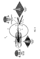
- FIG. 1 shows a conventional Gaussian profile in a LIDAR transmitter and its relationship in the far-field to a receiver FPA projection;
- FIG. 2 shows a near top hat intensity profile or a top hat-like intensity profile of a laser beam and its relationship in the far-field to a receiver FPA projection;
- FIG. 3 is a schematic diagram of a LIDAR transmitter in which a laser beam at the near-field having a Bessel intensity profile is transmitted through the LIDAR transmitter to obtain a top hat laser intensity profile in the far-field, according to an embodiment
- FIG. 4 is a schematic diagram of a process for transforming a laser beam having Gaussian intensity profile into a radiation beam having a Bessel intensity profile, according to an embodiment
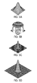
- FIG. 5A depicts a Gaussian intensity profile of a laser beam input
- FIG. 5B depicts a top hat intensity profile obtained by reformatting the Gaussian profile depicted in FIG. 5A ;
- FIG. 5C depicts a Bessel intensity profile obtained by Fourier transforming the top hat intensity profile depicted in FIG. 5B .
- FIG. 5D depicts an expanded Bessel intensity profile obtained by expanding the Bessel intensity profile depicted in FIG. 5C ;
- FIG. 6A shows a detailed ray trace of the operation of a conventional Gaussian to top hat reformatting optical system
- FIG. 6B shows an example of a conventional Fourier transforming imager optical system
- FIG. 6C shows an example of a conventional beam expansion optical system
- FIG. 7A is a graph showing a computed Fourier transform of a central lobe of a Bessel function
- FIG. 7B is a graph showing a computed Fourier transform of a Bessel function truncated at two rings
- FIG. 7C is a graph showing a computed Fourier transform of a Bessel function truncated at five rings
- FIG. 7D is a graph showing a computed Fourier transform of a Bessel function truncated at ten rings
- FIG. 8A is an isometric view of a "three-mirror" optical Fourier transform system combining the functions of a Fourier transform imager and a beam expander, according to an embodiment of the present disclosure
- FIG. 8B is a side view of the "three-mirror" optical system shown in FIG. 8A ;
- FIG. 8C is a top view of the "three-mirror" optical system shown in FIG. 8A ;
- FIG. 9A is a schematic representation of a conventional f-f optical configuration.
- FIG. 9B is a schematic representation of the optical system shown in FIG. 8A .
- FIG. 2 shows a near top hat intensity profile or a top hat-like intensity profile of a laser beam, according to an embodiment of the present disclosure.
- the near top hat laser intensity profile can be the Fourier transform of a five ring Bessel intensity profile.
- the near top hat laser profile can be the transform of a ten ring Bessel intensity profile.
- the near top hat laser intensity profile in the far-field is shown in relation to a receiver FPA projection.
- the relatively flat intensity level at the top of the near top hat laser intensity profile is slightly higher or approximately the same as an ideal threshold intensity level needed for the FPA detector to output a meaningful signal. Also, as shown in FIG.
- the intensity in the side wings of the near top hat laser intensity profile follows approximately the projection of the field of view (FOV) of the FPA detector.
- FOV field of view
- the energy wasted at the side wings of the of the near top hat laser intensity profile is substantially minimized.
- the near top hat nature of the transmitter beam puts only the required energy on the detector, with very small energy losses outside the field of view (FOV) of the detector.
- a smaller tolerance on Transmit/Receive boresight allows a smaller overall transmitter divergence and less intensity loss.
- FIG. 3 is a schematic diagram of a LIDAR transmitter in which a laser beam at the near-field having a Bessel intensity profile is transmitted through the LIDAR transmitter to obtain a top hat laser intensity profile in the far-field, according to an embodiment of the present disclosure.
- LIDAR transmitter 10 includes primary mirror 12, secondary mirror 14 and tertiary mirror 16.
- LIDAR transmitter 10 can be seen as an afocal three-mirror anastigmat optical system.
- a detailed description of an afocal three-mirror anastigmat optical system can be found in U.S. Patent No. 3,674,334 , the content of which is incorporated herein in its entirety.
- LIDAR transmitter 10 further includes transmitter-receiver (T/R) mirror 18.
- T/R mirror 18 has a hole 19 on its periphery.
- LIDAR transmitter 10 further includes beam steering mirror (BSM) 20 and static flat fold mirror 22.
- BSM beam steering mirror
- a laser beam having a Gaussian intensity profile is transformed into a beam having a Bessel intensity profile by an optical beam profile shaping apparatus (not shown in FIG. 3 ) that will be described in detail in the following paragraphs.
- the beam having the Bessel intensity profile in the near-field is input into LIDAR transmitter 10 and directed towards hole 19 in T/R mirror 18, as depicted in FIG. 3 .
- T/R mirror 18 passes the input radiation beam and reflects the returning received radiation.
- the beam having the Bessel intensity profile traverses hole 19 in T/R mirror 18 to impinge upon BSM 20 which steers the beam towards tertiary mirror 16.
- Tertiary mirror 16 is a focusing mirror.
- Tertiary mirror 16 focuses the beam at a focus point near static flat fold mirror 22.
- the intensity profile of the beam at or near the focus point is a top hat intensity profile.
- the beam with the top hat intensity profile impinges static flat fold mirror 22, which directs the beam through opening 13 in primary mirror 12 towards secondary mirror 14.
- Secondary mirror 14 is a negative power diverging mirror.
- the beam is reflected back by secondary mirror 14 towards primary mirror 12.
- the beam reflected by secondary mirror 14 is then reflected by primary mirror 14 which sends the collimated beam to the far-field for large distances (e.g., hundreds to thousands of kilometers).
- the intensity profile of the beam after reflection from primary mirror 12 is transformed back to a near-field Bessel intensity profile, as shown in FIG. 3 .
- the beam intensity profile at far-field is a top hat intensity profile (as shown in FIG. 3 ).
- the beam output at far-field has a top hat intensity profile.
- the profile of the output beam of the LIDAR transmitter 10 at far-field would have been a Gaussian intensity profile. Therefore, rather than transmit a near-field Gaussian profile to obtain a far-field Gaussian profile, which is not desirable as discussed above, one would instead transmit a near-field truncated Bessel profile to obtain an approximate top-hat function or profile at far-field.
- FIG. 4 is a schematic diagram of steps for transforming a laser beam having Gaussian intensity profile into a beam having a Bessel intensity profile, according to an embodiment.
- a laser outputs a beam having a Gaussian intensity profile A (shown in FIG. 5A ), at S10, such as the Gaussian intensity profile of the fundamental mode TEM 00 .
- the beam having the Gaussian profile A is reformatted into a beam having a top hat intensity profile B (shown in FIG. 5B ) using conventional refractive optical system (reformatting optical system) 60, at S20.
- FIG. 6A An example of conventional refractive optical system 60 for transforming a beam having a Gaussian intensity profile into a beam having a top hat intensity profile is shown in FIG. 6A.
- FIG. 6A An example of conventional refractive optical system 60 for transforming a beam having a Gaussian intensity profile into a beam having a top hat intensity profile is shown in FIG. 6A.
- FIG. 6A
- Gaussian to top hat reformatting optical system 60 includes a pair of optical elements 61, 62 having aspherical optical surfaces. Rays near the edge of the Gaussian beam intensity profile input which carry very little energy are significantly compressed, while the rays near the center of the Gaussian beam intensity profile input which carry most of the energy are not compressed, resulting in the Gaussian beam intensity profile being transformed into a top hat beam intensity profile.
- the beam with the top hat intensity profile B is input through a Fourier transforming imager optical system or Fourier transform imager, at S30 to transform the beam having the top hat intensity profile B (shown in FIG. 5B ) into a beam having a Bessel intensity profile C (shown in FIG. 5C ).
- FIG. 6B shows an example of conventional Fourier transforming imager optical system 64.
- Fourier transforming imager optical system 64 includes two mirrors 65 and 66. The beam having a top hat intensity profile impinges first mirror 65 which focuses and directs the beam towards the second mirror 66.
- first mirror 65 receives the beam having the top hat intensity profile from reformatting optical system 60, and directs the beam towards second mirror 66.
- Second mirror 66 directs the beam towards beam expansion optical system (beam expander) 68 for further processing.
- the beam directed towards beam expander 68 is a Bessel intensity profile C (as shown in FIG. 5C ).
- the beam output by Fourier transforming imager optical system 64 having the Bessel intensity profile C (shown in FIG. 5C ) is input into beam expansion optical system (beam expander) 68 at S40 to obtain an expanded beam with a Bessel intensity profile D (shown in FIG. 5D ).
- FIG. 6C shows an example of conventional beam expansion optical system (beam expander) 68.
- beam expansion optical system 68 includes two mirrors 67 and 69.
- the beam having a smaller Bessel intensity profile impinges first mirror 67 (i.e., the first mirror 67 receives the beam having the smaller Bessel intensity profile) which expands or enlarges and directs the beam towards second mirror 69.
- Second mirror 69 directs the beam having an expanded Bessel intensity profile towards an output of beam expander 68 to be transmitted to other optical systems for further processing.
- conventional beam expansion optical system (beam expander) 68 may be utilized to scale and truncate the Bessel intensity profile.
- the beam output by beam expander 68 having a Bessel intensity profile D (shown in FIG. 5D ) is inserted or input at S50 in the beam delivery optical system such as the LIDAR transmitter 10, through T/R mirror 18.
- the ideal top hat function and the Bessel function are known Fourier Transform pairs.
- the Bessel function In order to get an ideal top hat function from a transformed Bessel function, the Bessel function must extend to infinity.
- selecting a Bessel function that extends to infinity can put a burden on the user to provide such a Bessel function, such as requiring the use of large optics. Therefore, an approximate solution may be selected in which the burden is limited by selecting a truncated Bessel function, but which, when Fourier transformed, would result in a top hat-like function approximating an ideal top hat function.
- FIG. 7A is a graph showing a computed Fourier transform of a central lobe of a Bessel function.
- FIG. 7B is a graph showing a computed Fourier transform of a Bessel function truncated at two "rings.”
- FIG. 7C is a graph showing a computed Fourier transform of a Bessel function truncated at five "rings.”
- FIG. 7D is a graph showing a computed Fourier transform of a Bessel function truncated at ten "rings.” As shown in FIG.
- truncation at the first Bessel zero gives a remarkably good approximation to a Gaussian function. This is because the central peak of the Bessel function is very Gaussian-like.
- truncation of the Bessel function at two rings results in a Fourier transform resembling twin mountain peaks.
- truncation of the Bessel function at 5 Bessel rings gives a good approximation to the desired top hat profile.
- FIG. 7D truncation of the Bessel function at 10 Bessel rings, provides a somewhat flatter top with more and smaller oscillations across the top hat, and results in the sides being somewhat steeper.
- a Bessel function truncated at 5 rings or more provides the desired approximate or near top hat profile.
- the process of Fourier transforming the top hat illumination beam to a sinc (or Bessel) function with the desired scale or size can be done theoretically and sometimes practically by the process shown in FIG. 4 .
- the imager, i.e., the Fourier transform imager, 64 is used for transforming the top hat intensity profile (output by the reformatting optical system 60) into the Bessel intensity profile, followed by the beam expander 68 to achieve the desired size for the Bessel intensity profile.
- the Fourier transform of a top hat function is a sinc function (sin x / x) or a Bessel function of the first kind.
- the diameter D sinc of the central maximum of the sinc function (or Bessel function) is given by the equation (1).
- D sin ⁇ c 2 ⁇ ⁇ ⁇ F number where the F number is equal to the focal length f divided by the effective aperture diameter D aperture , as shown in equation (2).
- F number f D aperture
- beam, object, function, and illumination pattern or profile can be used interchangeably to describe the input to be transformed.
- imager, optic, optical system, and lens can be used interchangeably to describe the apparatus that performs the optical Fourier transform, i.e., the optical beam profile shaping apparatus.
- a true Fourier transform is only achieved in a f-f configuration.
- the function (or illumination pattern, shape, profile or object) to be transformed is located one focal length in front of the lens of focal length f, and the Fourier transform is present at a location that is one focal length behind the lens, at a distance f from the lens.
- this condition is also called the telecentric condition, where the chief rays (i.e., rays passing through the center of the object at various angles) are all parallel to each other.
- the Fourier transform is still located one focal length behind the optic, but the transform contains a quadratic phase term that is either + or -, depending on whether the object is closer or farther than one focal length from the optic.
- a quadratic phase term that is either + or -, depending on whether the object is closer or farther than one focal length from the optic.
- the object In order to achieve a true Fourier transform without the quadratic phase term, the object (function, profile or pattern) must be located one focal length in front of the transforming lens or optic. If, as discussed in the above paragraphs, a long focal length lens (needed to achieve a large size sinc function) can create a size problem, the requirement to locate the object one focal length in front of the optic can further compound the size problem.
- the object in the telecentric configuration, may also serve as a stop. Alternatively, or in addition, a stop may be provided on the object side.
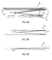
- FIG. 8A is an isometric view of "three-mirror" optical Fourier transform system 80 combining the functions of the Fourier transform imager and the beam expander, according to an embodiment.
- FIG. 8B is a side view of the three-mirror optical system shown in FIG. 8A.
- FIG. 8C is a top view of the three-mirror optical system shown in FIG. 8A .
- optical system 80 combining the functions of the Fourier transform imager and the beam expander has, in fact, two mirrors 82 and 84.
- first (primary) and third (tertiary) mirrors are the same, and single mirror 82 has one reflection prior to a reflection from second mirror 84 and one reflection subsequent to reflection from the second mirror 84.
- First mirror 82 may be configured to receive the radiation beam having the top hat intensity profile from reformatting optical system 60 and reflect the radiation beam towards second mirror 84.
- Second mirror 84 may be configured to reflect the radiation beam received from first mirror 82 towards third mirror 82 (in this embodiment the first mirror and the third mirror are a single and same mirror).
- Third mirror 82 may be configured to direct the radiation beam received from second mirror 84 towards an output of Fourier transforming optical system 80.
- first two mirrors (first or primary mirror 82 and second or secondary mirror 84) form a high telephoto ratio Cassegrain that compress the physical length between first mirror 82 and second mirror 84 relative to the focal length of the Cassegrain
- third or tertiary mirror 82 (which in the embodiment illustrated is the same as first or primary mirror 82) is a positive power field mirror to achieve the telecentric condition to relax the "one focal length" distance requirement for placement of the object to be transformed.
- Optical system 80 depicted above is compact, in that its overall physical length is about 1/28 of the length needed to achieve the f-f configuration. Further, optical system 80 is telecentric, so the true Fourier transform is created without any quadratic phase term. In one embodiment, optical system 80 can accept a rectangular shaped input (for example, as shown in FIGs. 8A, 8B and 8C with an aspect ratio of 1:4) and operate at very slow F umbers (e.g., F/245 by F/981).
- F umbers e.g., F/245 by F/981
- optical system 80 can be used at any wavelength in the infrared spectrum (IR), the visible spectrum, or the ultraviolet spectrum, as desired.
- IR infrared spectrum
- visible spectrum visible spectrum
- ultraviolet spectrum ultraviolet spectrum
- a specific prescription for an embodiment of the optical system illustrated in FIGs. 8A, 8B and 8C is given in Table 1.
- Table 1 Description Surface Radius Conic Constant Thickness Material Entrance Pupil 1 ⁇ n/a 35.0000 Air Primary 2 -52.9056 -1.000000 -25.0092 Reflective Secondary 3 -2.8612 -0.962637 25.0092 Reflective Tertiary 4 -52.9056 -1.000000 -30.0000 Air Image 5 ⁇ n/a n/a Air Entrance Aperture Dimension is 0.5 in y-direction by 2.0 in x-direction Aperture offset is 2.0 in y-direction FOV offset is 0.2 deg. in alpha Focal length F is 489.17 F number is F/978 (or about 978) in y-direction by F/245 (or about 245) in x-direction Effective FOV diameter is 0.04 deg.
- optical Fourier transform system classical or conventional f-f configuration 90, illustrated in FIG. 9A , for focal length (f) equal to about 4.9 meter would have an overall length D of about 9.8 meters (2 x 4.9 m) or about 386 inches.
- the "three mirror" optical Fourier transform such as optical system 80 reduces the length of the optical Fourier transform system, i.e., the length L between first mirror 82 and second mirror 84, to about 14 inches (about 0.35 m).
- a reduction in length by a factor of about 28 can be achieved (i.e., D/L is equal to about 28).
- the length of optical Fourier transform system can be reduced by a factor of at least about 20.
Landscapes
- Physics & Mathematics (AREA)
- General Physics & Mathematics (AREA)
- Optics & Photonics (AREA)
- Lenses (AREA)
Applications Claiming Priority (1)
| Application Number | Priority Date | Filing Date | Title |
|---|---|---|---|
| US12/359,645 US8277060B2 (en) | 2009-01-26 | 2009-01-26 | Apparatus and method of shaping a laser beam profile |
Publications (2)
| Publication Number | Publication Date |
|---|---|
| EP2211202A1 true EP2211202A1 (fr) | 2010-07-28 |
| EP2211202B1 EP2211202B1 (fr) | 2015-09-16 |
Family
ID=42063286
Family Applications (1)
| Application Number | Title | Priority Date | Filing Date |
|---|---|---|---|
| EP10151170.7A Active EP2211202B1 (fr) | 2009-01-26 | 2010-01-20 | Appareil et procédé pour former un profil de faisceau laser |
Country Status (2)
| Country | Link |
|---|---|
| US (1) | US8277060B2 (fr) |
| EP (1) | EP2211202B1 (fr) |
Cited By (4)
| Publication number | Priority date | Publication date | Assignee | Title |
|---|---|---|---|---|
| WO2019041268A1 (fr) * | 2017-08-31 | 2019-03-07 | SZ DJI Technology Co., Ltd. | Système de détection et télémétrie de la distance par la lumière (lidar) à semi-conducteurs |
| CN109683330A (zh) * | 2019-01-30 | 2019-04-26 | 复旦大学 | 通过光纤端面生长微锥产生类贝塞尔光束的方法 |
| CN110749421A (zh) * | 2018-07-24 | 2020-02-04 | 深圳市矽电半导体设备有限公司 | 发光器件测试一体机 |
| US11675076B2 (en) | 2017-08-31 | 2023-06-13 | SZ DJI Technology Co., Ltd. | Solid state light detection and ranging (LIDAR) system and system and method for improving solid state light detection and ranging (LIDAR) resolution |
Families Citing this family (19)
| Publication number | Priority date | Publication date | Assignee | Title |
|---|---|---|---|---|
| US7157908B1 (en) * | 2002-12-10 | 2007-01-02 | Fonar Corporation | Magnetic resonance imaging using bessel functions |
| DE102009035582A1 (de) * | 2009-07-29 | 2011-02-03 | Carl Zeiss Sms Gmbh | Vergrößernde abbildende Optik sowie Metrologiesystem mit einer derartigen abbildenden Optik |
| WO2013188602A1 (fr) | 2012-06-13 | 2013-12-19 | Kla-Tencor Corporation | Systèmes de balayage de surface optique et procédés associés |
| DE102013201139A1 (de) * | 2013-01-24 | 2014-07-24 | Fraunhofer-Gesellschaft zur Förderung der angewandten Forschung e.V. | Verfahren und Vorrichtung zur Begrenzung einer transmittierten optischen Leistung und Entfernungsmesser |
| CN105612611B (zh) | 2013-08-09 | 2019-03-12 | 科磊股份有限公司 | 用于提高检测灵敏度的多点照明 |
| US10209526B2 (en) * | 2014-01-20 | 2019-02-19 | Yakov Soskind | Electromagnetic radiation enhancement methods and systems |
| WO2015179347A1 (fr) * | 2014-05-22 | 2015-11-26 | Carrier Corporation | Détecteur de fumée ponctuel sans chambre à large zone de couverture |
| US10018851B2 (en) | 2014-08-14 | 2018-07-10 | Yakov Soskind | Optical field transformation methods and systems |
| US9601904B1 (en) | 2015-12-07 | 2017-03-21 | Raytheon Company | Laser diode driver with variable input voltage and variable diode string voltage |
| US10042172B2 (en) | 2015-12-23 | 2018-08-07 | Institut National D'optique | Optical beam conditioning device with coherence-breaking and beam transforming modules |
| KR102423775B1 (ko) * | 2016-08-30 | 2022-07-22 | 코닝 인코포레이티드 | 투명 재료의 레이저 가공 |
| US20180128904A1 (en) * | 2016-11-07 | 2018-05-10 | Uber Technologies, Inc. | Lidar scanner with optical amplification |
| US11860316B1 (en) * | 2018-08-21 | 2024-01-02 | Innovusion, Inc. | Systems and method for debris and water obfuscation compensation for use in LiDAR systems |
| US10884252B2 (en) | 2018-12-26 | 2021-01-05 | Raytheon Company | Compact transform optics for spectral beam combining |
| US11754680B2 (en) | 2020-04-20 | 2023-09-12 | Raytheon Company | Optical system that detects and blocks backscatter |
| US11619709B2 (en) | 2020-04-20 | 2023-04-04 | Raytheon Company | Optical system to reduce local internal backscatter |
| US11268860B2 (en) | 2020-07-24 | 2022-03-08 | Raytheon Company | Radiometric calibration of detector |
| IL284740B2 (en) | 2021-07-08 | 2023-05-01 | Elbit Systems Electro Optics Elop Ltd | Optical correction component for coherent beam combining systems and coherent beam combining methods and systems using an optical correction component |
| US12461379B2 (en) | 2021-07-13 | 2025-11-04 | Raytheon Company | Reflective gaussian to flat-top and other beam shapers |
Citations (6)
| Publication number | Priority date | Publication date | Assignee | Title |
|---|---|---|---|---|
| US3674334A (en) | 1971-01-04 | 1972-07-04 | Perkin Elmer Corp | Catoptric anastigmatic afocal optical system |
| US6022114A (en) * | 1998-05-01 | 2000-02-08 | Nikon Corporation | Anamorphic afocal beam shaping assembly |
| US20030179452A1 (en) * | 2002-03-18 | 2003-09-25 | Lizotte Todd E. | Beam or wave front |
| US6975458B1 (en) * | 2001-07-13 | 2005-12-13 | Kurt Kanzler | Method and apparatus for transformation of a gaussian laser beam to a far field diffraction pattern |
| EP1617257A1 (fr) * | 2004-07-16 | 2006-01-18 | CARL ZEISS JENA GmbH | Dispositif d'éclairage pour un microscope à balayage avec dispositif pour transformer la distribution d'intensité |
| US20070242327A1 (en) * | 2006-02-23 | 2007-10-18 | Karlton Powell | Scanned beam source and systems using a scanned beam source for producing a wavelength-compensated composite beam of light |
Family Cites Families (9)
| Publication number | Priority date | Publication date | Assignee | Title |
|---|---|---|---|---|
| US4101195A (en) | 1977-07-29 | 1978-07-18 | Nasa | Anastigmatic three-mirror telescope |
| US5343415A (en) | 1990-08-31 | 1994-08-30 | Matsushita Electric Industrial Co., Ltd. | Logarithmic polar coordinate transforming method, vision recognizing method, and optical information processing apparatus |
| JPH05134192A (ja) * | 1991-05-02 | 1993-05-28 | Hughes Aircraft Co | 多数の同時機能を有する光学系 |
| US5170284A (en) | 1991-08-16 | 1992-12-08 | Hughes Aircraft Company | Wide field of view focal three-mirror anastigmat |
| DK120692D0 (da) | 1992-09-30 | 1992-09-30 | Risoe Forskningscenter | Rotationsmaaling |
| JPH09211330A (ja) * | 1996-01-29 | 1997-08-15 | Canon Inc | 反射光学系 |
| US20020011852A1 (en) * | 2000-03-21 | 2002-01-31 | Andreas Mandelis | Non-contact photothermal radiometric metrologies and instrumentation for characterization of semiconductor wafers, devices and non electronic materials |
| US7741618B2 (en) * | 2004-11-19 | 2010-06-22 | Science & Engineering Services, Inc. | Enhanced portable digital lidar system |
| US8358888B2 (en) * | 2008-04-10 | 2013-01-22 | Ofs Fitel, Llc | Systems and techniques for generating Bessel beams |
-
2009
- 2009-01-26 US US12/359,645 patent/US8277060B2/en active Active
-
2010
- 2010-01-20 EP EP10151170.7A patent/EP2211202B1/fr active Active
Patent Citations (6)
| Publication number | Priority date | Publication date | Assignee | Title |
|---|---|---|---|---|
| US3674334A (en) | 1971-01-04 | 1972-07-04 | Perkin Elmer Corp | Catoptric anastigmatic afocal optical system |
| US6022114A (en) * | 1998-05-01 | 2000-02-08 | Nikon Corporation | Anamorphic afocal beam shaping assembly |
| US6975458B1 (en) * | 2001-07-13 | 2005-12-13 | Kurt Kanzler | Method and apparatus for transformation of a gaussian laser beam to a far field diffraction pattern |
| US20030179452A1 (en) * | 2002-03-18 | 2003-09-25 | Lizotte Todd E. | Beam or wave front |
| EP1617257A1 (fr) * | 2004-07-16 | 2006-01-18 | CARL ZEISS JENA GmbH | Dispositif d'éclairage pour un microscope à balayage avec dispositif pour transformer la distribution d'intensité |
| US20070242327A1 (en) * | 2006-02-23 | 2007-10-18 | Karlton Powell | Scanned beam source and systems using a scanned beam source for producing a wavelength-compensated composite beam of light |
Non-Patent Citations (2)
| Title |
|---|
| JOSEPH W. GOODMAN: "Introduction to Fourier Optics", MCGRAW-HILL |
| JOSEPH W. GOODMAN: "Introduction to Fourier Optics", MCGRAW-HILL, pages: 62 - 65 |
Cited By (4)
| Publication number | Priority date | Publication date | Assignee | Title |
|---|---|---|---|---|
| WO2019041268A1 (fr) * | 2017-08-31 | 2019-03-07 | SZ DJI Technology Co., Ltd. | Système de détection et télémétrie de la distance par la lumière (lidar) à semi-conducteurs |
| US11675076B2 (en) | 2017-08-31 | 2023-06-13 | SZ DJI Technology Co., Ltd. | Solid state light detection and ranging (LIDAR) system and system and method for improving solid state light detection and ranging (LIDAR) resolution |
| CN110749421A (zh) * | 2018-07-24 | 2020-02-04 | 深圳市矽电半导体设备有限公司 | 发光器件测试一体机 |
| CN109683330A (zh) * | 2019-01-30 | 2019-04-26 | 复旦大学 | 通过光纤端面生长微锥产生类贝塞尔光束的方法 |
Also Published As
| Publication number | Publication date |
|---|---|
| US20100188762A1 (en) | 2010-07-29 |
| EP2211202B1 (fr) | 2015-09-16 |
| US8277060B2 (en) | 2012-10-02 |
Similar Documents
| Publication | Publication Date | Title |
|---|---|---|
| EP2211202B1 (fr) | Appareil et procédé pour former un profil de faisceau laser | |
| US7199877B2 (en) | Scalable imaging spectrometer | |
| EP3052907B1 (fr) | Spectromètre monolithique | |
| US11579459B2 (en) | Polychromator systems and methods | |
| US20080266687A1 (en) | All-reflective, wide-field-of-view, inverse-telephoto optical system with external posterior aperture stop and long back focal length | |
| JP5970129B2 (ja) | 全反射性の実の瞳のテレセントリックなイメージャ | |
| US10823659B2 (en) | One dimensional beam homogenization with a single aspheric lens for accurate particle sizing instrumentation | |
| US20210131869A1 (en) | Compact freeform echelle spectrometer | |
| De Korte et al. | EXOSAT x-ray imaging optics | |
| JP2023508607A (ja) | 平行サンプルビームを有する光学分光プローブにおける干渉を軽減するための装置および方法 | |
| CN108051083A (zh) | 一种光谱成像装置 | |
| RU2621364C1 (ru) | Автоколлимационный спектрометр со спектральным разложением в сагиттальном направлении | |
| US3048080A (en) | Spectroscopic device | |
| CN110501074B (zh) | 高通量宽谱段高分辨率的相干色散光谱成像方法及装置 | |
| CN104019893B (zh) | Offner结构成像光谱仪 | |
| Khazanov | Analytical dependence of time contrast ratio on surface imperfection of optics in femtosecond lasers | |
| US20220252871A1 (en) | Method for designing freeform concave grating imaging spectrometer | |
| CN119882233A (zh) | 高光谱成像低畸变大像面物像双远心光谱仪及实现方法 | |
| Freudenthaler | Effects of spatially inhomogeneous photomultiplier sensitivity on lidar signals and remedies | |
| CN208902264U (zh) | 基于自由曲面及曲面棱镜的成像光谱仪光学系统 | |
| Serkan et al. | Off-axis mirror based optical system design for circularization, collimation, and expansion of elliptical laser beams | |
| CN117490860A (zh) | 成像型超高光谱分辨率傅里叶光谱仪点光源光谱定标方法 | |
| Braig et al. | Diffraction compensation of slope errors on strongly curved grating substrates | |
| Baker et al. | Highly replicable, low-cost, portable, general-purpose, high-resolution spectrometer with applications in stellar studies and exoplanet science | |
| Nemes et al. | Laser beam characterization |
Legal Events
| Date | Code | Title | Description |
|---|---|---|---|
| PUAI | Public reference made under article 153(3) epc to a published international application that has entered the european phase |
Free format text: ORIGINAL CODE: 0009012 |
|
| AK | Designated contracting states |
Kind code of ref document: A1 Designated state(s): AT BE BG CH CY CZ DE DK EE ES FI FR GB GR HR HU IE IS IT LI LT LU LV MC MK MT NL NO PL PT RO SE SI SK SM TR |
|
| AX | Request for extension of the european patent |
Extension state: AL BA RS |
|
| 17P | Request for examination filed |
Effective date: 20110126 |
|
| 17Q | First examination report despatched |
Effective date: 20120305 |
|
| REG | Reference to a national code |
Ref country code: DE Ref legal event code: R079 Ref document number: 602010027509 Country of ref document: DE Free format text: PREVIOUS MAIN CLASS: G01S0017000000 Ipc: G02B0019000000 |
|
| GRAP | Despatch of communication of intention to grant a patent |
Free format text: ORIGINAL CODE: EPIDOSNIGR1 |
|
| RIC1 | Information provided on ipc code assigned before grant |
Ipc: G02B 17/06 20060101ALI20150409BHEP Ipc: G02B 19/00 20060101AFI20150409BHEP Ipc: G01S 17/00 20060101ALI20150409BHEP Ipc: G02B 27/09 20060101ALI20150409BHEP |
|
| INTG | Intention to grant announced |
Effective date: 20150513 |
|
| GRAS | Grant fee paid |
Free format text: ORIGINAL CODE: EPIDOSNIGR3 |
|
| GRAA | (expected) grant |
Free format text: ORIGINAL CODE: 0009210 |
|
| AK | Designated contracting states |
Kind code of ref document: B1 Designated state(s): AT BE BG CH CY CZ DE DK EE ES FI FR GB GR HR HU IE IS IT LI LT LU LV MC MK MT NL NO PL PT RO SE SI SK SM TR |
|
| REG | Reference to a national code |
Ref country code: GB Ref legal event code: FG4D |
|
| REG | Reference to a national code |
Ref country code: CH Ref legal event code: EP |
|
| REG | Reference to a national code |
Ref country code: IE Ref legal event code: FG4D |
|
| REG | Reference to a national code |
Ref country code: AT Ref legal event code: REF Ref document number: 750230 Country of ref document: AT Kind code of ref document: T Effective date: 20151015 |
|
| REG | Reference to a national code |
Ref country code: DE Ref legal event code: R096 Ref document number: 602010027509 Country of ref document: DE |
|
| REG | Reference to a national code |
Ref country code: FR Ref legal event code: PLFP Year of fee payment: 7 |
|
| REG | Reference to a national code |
Ref country code: NL Ref legal event code: MP Effective date: 20150916 |
|
| PG25 | Lapsed in a contracting state [announced via postgrant information from national office to epo] |
Ref country code: LT Free format text: LAPSE BECAUSE OF FAILURE TO SUBMIT A TRANSLATION OF THE DESCRIPTION OR TO PAY THE FEE WITHIN THE PRESCRIBED TIME-LIMIT Effective date: 20150916 Ref country code: NO Free format text: LAPSE BECAUSE OF FAILURE TO SUBMIT A TRANSLATION OF THE DESCRIPTION OR TO PAY THE FEE WITHIN THE PRESCRIBED TIME-LIMIT Effective date: 20151216 Ref country code: FI Free format text: LAPSE BECAUSE OF FAILURE TO SUBMIT A TRANSLATION OF THE DESCRIPTION OR TO PAY THE FEE WITHIN THE PRESCRIBED TIME-LIMIT Effective date: 20150916 Ref country code: LV Free format text: LAPSE BECAUSE OF FAILURE TO SUBMIT A TRANSLATION OF THE DESCRIPTION OR TO PAY THE FEE WITHIN THE PRESCRIBED TIME-LIMIT Effective date: 20150916 Ref country code: GR Free format text: LAPSE BECAUSE OF FAILURE TO SUBMIT A TRANSLATION OF THE DESCRIPTION OR TO PAY THE FEE WITHIN THE PRESCRIBED TIME-LIMIT Effective date: 20151217 |
|
| REG | Reference to a national code |
Ref country code: LT Ref legal event code: MG4D |
|
| REG | Reference to a national code |
Ref country code: AT Ref legal event code: MK05 Ref document number: 750230 Country of ref document: AT Kind code of ref document: T Effective date: 20150916 |
|
| PG25 | Lapsed in a contracting state [announced via postgrant information from national office to epo] |
Ref country code: HR Free format text: LAPSE BECAUSE OF FAILURE TO SUBMIT A TRANSLATION OF THE DESCRIPTION OR TO PAY THE FEE WITHIN THE PRESCRIBED TIME-LIMIT Effective date: 20150916 Ref country code: SE Free format text: LAPSE BECAUSE OF FAILURE TO SUBMIT A TRANSLATION OF THE DESCRIPTION OR TO PAY THE FEE WITHIN THE PRESCRIBED TIME-LIMIT Effective date: 20150916 |
|
| PG25 | Lapsed in a contracting state [announced via postgrant information from national office to epo] |
Ref country code: NL Free format text: LAPSE BECAUSE OF FAILURE TO SUBMIT A TRANSLATION OF THE DESCRIPTION OR TO PAY THE FEE WITHIN THE PRESCRIBED TIME-LIMIT Effective date: 20150916 |
|
| PG25 | Lapsed in a contracting state [announced via postgrant information from national office to epo] |
Ref country code: SK Free format text: LAPSE BECAUSE OF FAILURE TO SUBMIT A TRANSLATION OF THE DESCRIPTION OR TO PAY THE FEE WITHIN THE PRESCRIBED TIME-LIMIT Effective date: 20150916 Ref country code: CZ Free format text: LAPSE BECAUSE OF FAILURE TO SUBMIT A TRANSLATION OF THE DESCRIPTION OR TO PAY THE FEE WITHIN THE PRESCRIBED TIME-LIMIT Effective date: 20150916 Ref country code: IT Free format text: LAPSE BECAUSE OF FAILURE TO SUBMIT A TRANSLATION OF THE DESCRIPTION OR TO PAY THE FEE WITHIN THE PRESCRIBED TIME-LIMIT Effective date: 20150916 Ref country code: ES Free format text: LAPSE BECAUSE OF FAILURE TO SUBMIT A TRANSLATION OF THE DESCRIPTION OR TO PAY THE FEE WITHIN THE PRESCRIBED TIME-LIMIT Effective date: 20150916 Ref country code: IS Free format text: LAPSE BECAUSE OF FAILURE TO SUBMIT A TRANSLATION OF THE DESCRIPTION OR TO PAY THE FEE WITHIN THE PRESCRIBED TIME-LIMIT Effective date: 20160116 Ref country code: EE Free format text: LAPSE BECAUSE OF FAILURE TO SUBMIT A TRANSLATION OF THE DESCRIPTION OR TO PAY THE FEE WITHIN THE PRESCRIBED TIME-LIMIT Effective date: 20150916 |
|
| PG25 | Lapsed in a contracting state [announced via postgrant information from national office to epo] |
Ref country code: PT Free format text: LAPSE BECAUSE OF FAILURE TO SUBMIT A TRANSLATION OF THE DESCRIPTION OR TO PAY THE FEE WITHIN THE PRESCRIBED TIME-LIMIT Effective date: 20160118 Ref country code: BE Free format text: LAPSE BECAUSE OF NON-PAYMENT OF DUE FEES Effective date: 20160131 Ref country code: AT Free format text: LAPSE BECAUSE OF FAILURE TO SUBMIT A TRANSLATION OF THE DESCRIPTION OR TO PAY THE FEE WITHIN THE PRESCRIBED TIME-LIMIT Effective date: 20150916 Ref country code: RO Free format text: LAPSE BECAUSE OF FAILURE TO SUBMIT A TRANSLATION OF THE DESCRIPTION OR TO PAY THE FEE WITHIN THE PRESCRIBED TIME-LIMIT Effective date: 20150916 Ref country code: PL Free format text: LAPSE BECAUSE OF FAILURE TO SUBMIT A TRANSLATION OF THE DESCRIPTION OR TO PAY THE FEE WITHIN THE PRESCRIBED TIME-LIMIT Effective date: 20150916 |
|
| REG | Reference to a national code |
Ref country code: DE Ref legal event code: R097 Ref document number: 602010027509 Country of ref document: DE |
|
| PLBE | No opposition filed within time limit |
Free format text: ORIGINAL CODE: 0009261 |
|
| STAA | Information on the status of an ep patent application or granted ep patent |
Free format text: STATUS: NO OPPOSITION FILED WITHIN TIME LIMIT |
|
| 26N | No opposition filed |
Effective date: 20160617 |
|
| PG25 | Lapsed in a contracting state [announced via postgrant information from national office to epo] |
Ref country code: DK Free format text: LAPSE BECAUSE OF FAILURE TO SUBMIT A TRANSLATION OF THE DESCRIPTION OR TO PAY THE FEE WITHIN THE PRESCRIBED TIME-LIMIT Effective date: 20150916 Ref country code: LU Free format text: LAPSE BECAUSE OF FAILURE TO SUBMIT A TRANSLATION OF THE DESCRIPTION OR TO PAY THE FEE WITHIN THE PRESCRIBED TIME-LIMIT Effective date: 20160120 |
|
| REG | Reference to a national code |
Ref country code: CH Ref legal event code: PL |
|
| PG25 | Lapsed in a contracting state [announced via postgrant information from national office to epo] |
Ref country code: MC Free format text: LAPSE BECAUSE OF FAILURE TO SUBMIT A TRANSLATION OF THE DESCRIPTION OR TO PAY THE FEE WITHIN THE PRESCRIBED TIME-LIMIT Effective date: 20150916 |
|
| PG25 | Lapsed in a contracting state [announced via postgrant information from national office to epo] |
Ref country code: CH Free format text: LAPSE BECAUSE OF NON-PAYMENT OF DUE FEES Effective date: 20160131 Ref country code: LI Free format text: LAPSE BECAUSE OF NON-PAYMENT OF DUE FEES Effective date: 20160131 |
|
| REG | Reference to a national code |
Ref country code: IE Ref legal event code: MM4A |
|
| PG25 | Lapsed in a contracting state [announced via postgrant information from national office to epo] |
Ref country code: SI Free format text: LAPSE BECAUSE OF FAILURE TO SUBMIT A TRANSLATION OF THE DESCRIPTION OR TO PAY THE FEE WITHIN THE PRESCRIBED TIME-LIMIT Effective date: 20150916 |
|
| REG | Reference to a national code |
Ref country code: FR Ref legal event code: PLFP Year of fee payment: 8 |
|
| PG25 | Lapsed in a contracting state [announced via postgrant information from national office to epo] |
Ref country code: BE Free format text: LAPSE BECAUSE OF FAILURE TO SUBMIT A TRANSLATION OF THE DESCRIPTION OR TO PAY THE FEE WITHIN THE PRESCRIBED TIME-LIMIT Effective date: 20150916 |
|
| PG25 | Lapsed in a contracting state [announced via postgrant information from national office to epo] |
Ref country code: IE Free format text: LAPSE BECAUSE OF NON-PAYMENT OF DUE FEES Effective date: 20160120 |
|
| PG25 | Lapsed in a contracting state [announced via postgrant information from national office to epo] |
Ref country code: MT Free format text: LAPSE BECAUSE OF FAILURE TO SUBMIT A TRANSLATION OF THE DESCRIPTION OR TO PAY THE FEE WITHIN THE PRESCRIBED TIME-LIMIT Effective date: 20150916 |
|
| REG | Reference to a national code |
Ref country code: FR Ref legal event code: PLFP Year of fee payment: 9 |
|
| PG25 | Lapsed in a contracting state [announced via postgrant information from national office to epo] |
Ref country code: SM Free format text: LAPSE BECAUSE OF FAILURE TO SUBMIT A TRANSLATION OF THE DESCRIPTION OR TO PAY THE FEE WITHIN THE PRESCRIBED TIME-LIMIT Effective date: 20150916 Ref country code: CY Free format text: LAPSE BECAUSE OF FAILURE TO SUBMIT A TRANSLATION OF THE DESCRIPTION OR TO PAY THE FEE WITHIN THE PRESCRIBED TIME-LIMIT Effective date: 20150916 Ref country code: HU Free format text: LAPSE BECAUSE OF FAILURE TO SUBMIT A TRANSLATION OF THE DESCRIPTION OR TO PAY THE FEE WITHIN THE PRESCRIBED TIME-LIMIT; INVALID AB INITIO Effective date: 20100120 |
|
| PG25 | Lapsed in a contracting state [announced via postgrant information from national office to epo] |
Ref country code: MT Free format text: LAPSE BECAUSE OF FAILURE TO SUBMIT A TRANSLATION OF THE DESCRIPTION OR TO PAY THE FEE WITHIN THE PRESCRIBED TIME-LIMIT Effective date: 20160131 Ref country code: MK Free format text: LAPSE BECAUSE OF FAILURE TO SUBMIT A TRANSLATION OF THE DESCRIPTION OR TO PAY THE FEE WITHIN THE PRESCRIBED TIME-LIMIT Effective date: 20150916 Ref country code: TR Free format text: LAPSE BECAUSE OF FAILURE TO SUBMIT A TRANSLATION OF THE DESCRIPTION OR TO PAY THE FEE WITHIN THE PRESCRIBED TIME-LIMIT Effective date: 20150916 |
|
| PG25 | Lapsed in a contracting state [announced via postgrant information from national office to epo] |
Ref country code: BG Free format text: LAPSE BECAUSE OF FAILURE TO SUBMIT A TRANSLATION OF THE DESCRIPTION OR TO PAY THE FEE WITHIN THE PRESCRIBED TIME-LIMIT Effective date: 20150916 |
|
| P01 | Opt-out of the competence of the unified patent court (upc) registered |
Effective date: 20230530 |
|
| PGFP | Annual fee paid to national office [announced via postgrant information from national office to epo] |
Ref country code: GB Payment date: 20251219 Year of fee payment: 17 |
|
| PGFP | Annual fee paid to national office [announced via postgrant information from national office to epo] |
Ref country code: FR Payment date: 20251218 Year of fee payment: 17 |
|
| PGFP | Annual fee paid to national office [announced via postgrant information from national office to epo] |
Ref country code: DE Payment date: 20251217 Year of fee payment: 17 |