EP2211052A2 - Windturbinenturm und Montageverfahren mittels Friktionsschmieden - Google Patents
Windturbinenturm und Montageverfahren mittels Friktionsschmieden Download PDFInfo
- Publication number
- EP2211052A2 EP2211052A2 EP10150800A EP10150800A EP2211052A2 EP 2211052 A2 EP2211052 A2 EP 2211052A2 EP 10150800 A EP10150800 A EP 10150800A EP 10150800 A EP10150800 A EP 10150800A EP 2211052 A2 EP2211052 A2 EP 2211052A2
- Authority
- EP
- European Patent Office
- Prior art keywords
- friction
- forge
- fastener
- tower
- members
- Prior art date
- Legal status (The legal status is an assumption and is not a legal conclusion. Google has not performed a legal analysis and makes no representation as to the accuracy of the status listed.)
- Withdrawn
Links
- 238000000034 method Methods 0.000 title description 45
- 238000005242 forging Methods 0.000 title description 36
- 238000010438 heat treatment Methods 0.000 abstract description 17
- 230000008569 process Effects 0.000 description 24
- 239000000463 material Substances 0.000 description 9
- 238000003466 welding Methods 0.000 description 9
- 229910000831 Steel Inorganic materials 0.000 description 8
- 239000010959 steel Substances 0.000 description 8
- 239000002184 metal Substances 0.000 description 7
- 229910052751 metal Inorganic materials 0.000 description 7
- 238000010276 construction Methods 0.000 description 5
- 238000001816 cooling Methods 0.000 description 5
- 238000004519 manufacturing process Methods 0.000 description 5
- 238000013461 design Methods 0.000 description 4
- 238000010586 diagram Methods 0.000 description 4
- 230000008901 benefit Effects 0.000 description 3
- 238000005553 drilling Methods 0.000 description 3
- 230000006698 induction Effects 0.000 description 3
- 150000002739 metals Chemical class 0.000 description 3
- 238000003825 pressing Methods 0.000 description 3
- 229910000746 Structural steel Inorganic materials 0.000 description 2
- 230000000694 effects Effects 0.000 description 2
- 230000004927 fusion Effects 0.000 description 2
- 238000005304 joining Methods 0.000 description 2
- 238000012423 maintenance Methods 0.000 description 2
- 238000002485 combustion reaction Methods 0.000 description 1
- 230000006835 compression Effects 0.000 description 1
- 238000007906 compression Methods 0.000 description 1
- 230000008878 coupling Effects 0.000 description 1
- 238000010168 coupling process Methods 0.000 description 1
- 238000005859 coupling reaction Methods 0.000 description 1
- 230000007547 defect Effects 0.000 description 1
- 230000005672 electromagnetic field Effects 0.000 description 1
- 230000007613 environmental effect Effects 0.000 description 1
- 239000000945 filler Substances 0.000 description 1
- 230000004907 flux Effects 0.000 description 1
- 239000007789 gas Substances 0.000 description 1
- 239000012535 impurity Substances 0.000 description 1
- 238000007689 inspection Methods 0.000 description 1
- 239000000155 melt Substances 0.000 description 1
- 238000002844 melting Methods 0.000 description 1
- 230000008018 melting Effects 0.000 description 1
- 230000000737 periodic effect Effects 0.000 description 1
- 238000002360 preparation method Methods 0.000 description 1
- 230000004044 response Effects 0.000 description 1
- 230000000630 rising effect Effects 0.000 description 1
- 239000007787 solid Substances 0.000 description 1
- 230000001960 triggered effect Effects 0.000 description 1
- 230000003313 weakening effect Effects 0.000 description 1
Images


Classifications
-
- F—MECHANICAL ENGINEERING; LIGHTING; HEATING; WEAPONS; BLASTING
- F03—MACHINES OR ENGINES FOR LIQUIDS; WIND, SPRING, OR WEIGHT MOTORS; PRODUCING MECHANICAL POWER OR A REACTIVE PROPULSIVE THRUST, NOT OTHERWISE PROVIDED FOR
- F03D—WIND MOTORS
- F03D13/00—Assembly, mounting or commissioning of wind motors; Arrangements specially adapted for transporting wind motor components
- F03D13/20—Arrangements for mounting or supporting wind motors; Masts or towers for wind motors
-
- F—MECHANICAL ENGINEERING; LIGHTING; HEATING; WEAPONS; BLASTING
- F03—MACHINES OR ENGINES FOR LIQUIDS; WIND, SPRING, OR WEIGHT MOTORS; PRODUCING MECHANICAL POWER OR A REACTIVE PROPULSIVE THRUST, NOT OTHERWISE PROVIDED FOR
- F03D—WIND MOTORS
- F03D13/00—Assembly, mounting or commissioning of wind motors; Arrangements specially adapted for transporting wind motor components
- F03D13/10—Assembly of wind motors; Arrangements for erecting wind motors
-
- F—MECHANICAL ENGINEERING; LIGHTING; HEATING; WEAPONS; BLASTING
- F05—INDEXING SCHEMES RELATING TO ENGINES OR PUMPS IN VARIOUS SUBCLASSES OF CLASSES F01-F04
- F05B—INDEXING SCHEME RELATING TO WIND, SPRING, WEIGHT, INERTIA OR LIKE MOTORS, TO MACHINES OR ENGINES FOR LIQUIDS COVERED BY SUBCLASSES F03B, F03D AND F03G
- F05B2230/00—Manufacture
- F05B2230/20—Manufacture essentially without removing material
- F05B2230/23—Manufacture essentially without removing material by permanently joining parts together
- F05B2230/232—Manufacture essentially without removing material by permanently joining parts together by welding
- F05B2230/239—Inertia or friction welding
-
- F—MECHANICAL ENGINEERING; LIGHTING; HEATING; WEAPONS; BLASTING
- F05—INDEXING SCHEMES RELATING TO ENGINES OR PUMPS IN VARIOUS SUBCLASSES OF CLASSES F01-F04
- F05B—INDEXING SCHEME RELATING TO WIND, SPRING, WEIGHT, INERTIA OR LIKE MOTORS, TO MACHINES OR ENGINES FOR LIQUIDS COVERED BY SUBCLASSES F03B, F03D AND F03G
- F05B2230/00—Manufacture
- F05B2230/20—Manufacture essentially without removing material
- F05B2230/25—Manufacture essentially without removing material by forging
-
- Y—GENERAL TAGGING OF NEW TECHNOLOGICAL DEVELOPMENTS; GENERAL TAGGING OF CROSS-SECTIONAL TECHNOLOGIES SPANNING OVER SEVERAL SECTIONS OF THE IPC; TECHNICAL SUBJECTS COVERED BY FORMER USPC CROSS-REFERENCE ART COLLECTIONS [XRACs] AND DIGESTS
- Y02—TECHNOLOGIES OR APPLICATIONS FOR MITIGATION OR ADAPTATION AGAINST CLIMATE CHANGE
- Y02E—REDUCTION OF GREENHOUSE GAS [GHG] EMISSIONS, RELATED TO ENERGY GENERATION, TRANSMISSION OR DISTRIBUTION
- Y02E10/00—Energy generation through renewable energy sources
- Y02E10/70—Wind energy
- Y02E10/72—Wind turbines with rotation axis in wind direction
-
- Y—GENERAL TAGGING OF NEW TECHNOLOGICAL DEVELOPMENTS; GENERAL TAGGING OF CROSS-SECTIONAL TECHNOLOGIES SPANNING OVER SEVERAL SECTIONS OF THE IPC; TECHNICAL SUBJECTS COVERED BY FORMER USPC CROSS-REFERENCE ART COLLECTIONS [XRACs] AND DIGESTS
- Y02—TECHNOLOGIES OR APPLICATIONS FOR MITIGATION OR ADAPTATION AGAINST CLIMATE CHANGE
- Y02E—REDUCTION OF GREENHOUSE GAS [GHG] EMISSIONS, RELATED TO ENERGY GENERATION, TRANSMISSION OR DISTRIBUTION
- Y02E10/00—Energy generation through renewable energy sources
- Y02E10/70—Wind energy
- Y02E10/728—Onshore wind turbines
-
- Y—GENERAL TAGGING OF NEW TECHNOLOGICAL DEVELOPMENTS; GENERAL TAGGING OF CROSS-SECTIONAL TECHNOLOGIES SPANNING OVER SEVERAL SECTIONS OF THE IPC; TECHNICAL SUBJECTS COVERED BY FORMER USPC CROSS-REFERENCE ART COLLECTIONS [XRACs] AND DIGESTS
- Y02—TECHNOLOGIES OR APPLICATIONS FOR MITIGATION OR ADAPTATION AGAINST CLIMATE CHANGE
- Y02P—CLIMATE CHANGE MITIGATION TECHNOLOGIES IN THE PRODUCTION OR PROCESSING OF GOODS
- Y02P70/00—Climate change mitigation technologies in the production process for final industrial or consumer products
- Y02P70/50—Manufacturing or production processes characterised by the final manufactured product
Definitions
- a system in another embodiment, includes a press configured to linearly move a stud toward first and second members of a lattice structure, a drive configured to rotate the stud along an interface including both the first and second members to generate friction and heat to create a friction forge bond at the interface, and a heater configured to pre-heat or post heat treat the stud, the first member, the second member, or a combination thereof, relative to the creation of the friction forge bond.
- Embodiments of the present disclosure employ a friction forging technique for joining the structural components of a lattice-structure, such as a wind turbine tower.
- the improved lattice-structure wind turbine tower provides a high degree of mechanical strength compared to a tubular tower that uses the same amount of steel.
- the components of the wind tower may be more easily fabricated and transported to the construction site, compared to the sections of the much larger tubular structure.
- wind towers may be fabricated with hub heights as high as approximately 120 meters, 150 meters or higher.
- the friction forging techniques disclosed herein may be performed quickly and easily and provide a connection that is reliable under vibrational loading.
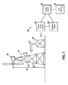
- FIG. 1 is a block diagram illustrating an embodiment of a system for fabricating an improved lattice-type tower using friction forge bonds.
- FIG. 1 depicts a wind turbine 10 supported by a lattice tower 12 constructed in accordance with certain embodiments of friction forge bonds.
- the tower 12 includes leg members 14 and cross members 16.
- the tower height 18, from the center of the wind turbine 10 to ground level may be approximately 120 to 150 meters or higher. In other embodiments, the height 18 may be less than 120 meters.
- the tower 12 may include any type of tower construction.
- the tower 12 may be a triangular (three sided) tower, square (four sided) tower, tapered self-supporting tower, guyed tower, etc.
- the wind turbine 10 and tower 12 may be located on a wind farm with several wind turbines 10 and towers 12.
- the tower 12 includes several tower sections 20 vertically stacked one over another. As indicated by arrow 22, the tower 12 may be constructed by fabricating individual tower sections 20 at ground level and then lifting the tower sections 20 into place. Each tower section 20 includes a lattice framework with a criss-crossed pattern of structural steel members. The steel members are coupled together using a tower construction system 24, which includes a friction forge system 26 for bonding the various structural members such as leg members 14 and cross-members 16. The friction forge system 26 will be described further below, in relation to FIG. 2 . In certain embodiments, the friction forge system 26 may be portable and/or manually positionable. As such, the friction forge system 26 may be positioned by hand during the fabrication of the tower section 20.
- the temperature sensor 37 may be any suitable temperature sensor such as a thermistor or thermocouple. Temperature data from the temperature sensor 37 may be sent to the controller 44 and processed for automatic control of the forging process. For example, the various stages of the friction forge process may be triggered in response to pre-programmed temperature targets or temperature versus time profiles. Furthermore, the forging pressure, rotational speed, heater output, etc. may also be based on the measured and/or the desired temperature profile. In some embodiments, the temperature data may be processed for display to a user of the friction forge system 26.
- the tower legs 14 and cross members 16 may be members may be made of any high strength structural steel, such as ASTM 572 grade 50 steel, for example. Furthermore, the tower legs 14 and cross members 16 may also be made with steel that exhibits low temperature toughness, and is, therefore, capable of operating at temperatures below approximately 30 or 40 degrees Fahrenheit below zero.
- the flanges 52 and the lugs 50 may be fastened to the leg member 14 by traditional welding techniques.
- the friction forge system 26 may use the heater 42 to pre-heat the forge area before rotating the fastener. Pre-heating the forge area may reduce the amount of rotational energy used to bring the forge interface up to the forging temperature. In some embodiments, the heater may raise the pre-forge temperature of the forge area to a value of up to approximately 600 to 700 degrees centigrade or more, up to the forging temperature. In some embodiments, the pre-heating may also be configured to influence the post-forge cooling characteristics of the forge area, as will be discussed further below.
- the strength and hardness properties of the thermo-mechanically affected zone 64 may be altered by the friction forging process.
- the friction forge bond 54 may undergo a post-forge heat treatment wherein the temperature and/or cooling rate of the thermo-mechanically affected zone 64 may be controlled using the heater 42.
- the heater 42 may raise the temperature of the friction forge bond 54 to approximately 500 to 750 degrees centigrade or higher. The temperature of the friction forge bond 54 may then be maintained for a time period of up to approximately 2 hours plus 15 minutes per inch of thickness of the joined workpieces.
- FIG. 5 illustrates an embodiment of a friction forge bond 50 wherein the lug 50 is partially predrilled.
- the opening 56 (marked by the forge interface 66) is formed by pre-drilling both the cross-member 16 and the lug 50.
- the sidewalls of the opening 56 are tapered to match the taper of the fastener 36.
- the pre-drilling of the lug 50 partially penetrates the lug 50 to create the bottom portion of the opening 56. In this way, the surface area of the forge interface 66 may be increased, resulting in a potentially stronger bond.
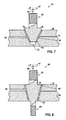
- FIG. 7 illustrates a friction forge bond 54 wherein the fastener 36 includes a threaded stud or projection 68 above a shoulder 70, and wherein the opening 56 includes a recess 72 located under the fastener 36.
- the threaded projection 68 may be used to attach a fixture to the tower 12 including another structural member or a non-structural member such as a power conduit, a lighting fixture, an antenna, etc.
- the fastener 36 may include the shoulder 70 for spacing the bolted fixture a certain distance away from the cross member 16.
- the projection 68 may include a hook, a loop, or any other type of fastening device.
- the friction forging process is a solid state process, wherein neither the joined pieces nor the fastener are heated to the melting point, but rather the lower forging temperature.
- the heat is created directly where it is needed, at the forge interface 66.
- the amount of heat produced by the friction forging process discussed herein may be relatively small compared to welding techniques such as arc welding or fusion welding, resulting in little or no deformation of the fastened workpieces, and using much less energy.
- the friction forging process may be used without surface preparation, fluxes, filler metals or shield gases.
- the friction forge bonds 54 are also more repeatable and reliable than typical welding processes, resulting in a reduced likelihood of defects compared to welding.
- Embodiments described herein therefore, provide an economical and reliable method of fabricating a lattice-type wind turbine tower. Particularly, wind turbine towers with heights greater than approximately 100 to 120 meters.
Landscapes
- Engineering & Computer Science (AREA)
- Life Sciences & Earth Sciences (AREA)
- Sustainable Development (AREA)
- Sustainable Energy (AREA)
- Chemical & Material Sciences (AREA)
- Combustion & Propulsion (AREA)
- Mechanical Engineering (AREA)
- General Engineering & Computer Science (AREA)
- Pressure Welding/Diffusion-Bonding (AREA)
- Wind Motors (AREA)
Applications Claiming Priority (1)
| Application Number | Priority Date | Filing Date | Title |
|---|---|---|---|
| US12/357,159 US20100180533A1 (en) | 2009-01-21 | 2009-01-21 | Wind turbine tower and assembly method using friction forging |
Publications (1)
| Publication Number | Publication Date |
|---|---|
| EP2211052A2 true EP2211052A2 (de) | 2010-07-28 |
Family
ID=42174580
Family Applications (1)
| Application Number | Title | Priority Date | Filing Date |
|---|---|---|---|
| EP10150800A Withdrawn EP2211052A2 (de) | 2009-01-21 | 2010-01-14 | Windturbinenturm und Montageverfahren mittels Friktionsschmieden |
Country Status (3)
| Country | Link |
|---|---|
| US (1) | US20100180533A1 (de) |
| EP (1) | EP2211052A2 (de) |
| JP (1) | JP2010167496A (de) |
Cited By (1)
| Publication number | Priority date | Publication date | Assignee | Title |
|---|---|---|---|---|
| EP2685090A1 (de) * | 2012-07-10 | 2014-01-15 | Siemens Aktiengesellschaft | Verfahren zum Herstellen einer Windturbinenstruktur und Windturbinenstruktur |
Families Citing this family (8)
| Publication number | Priority date | Publication date | Assignee | Title |
|---|---|---|---|---|
| JP5853405B2 (ja) * | 2011-04-25 | 2016-02-09 | 株式会社Ihi | 摩擦接合方法及び接合構造体 |
| US8915043B2 (en) | 2011-05-25 | 2014-12-23 | General Electric Company | Bolt connection for a wind tower lattice structure |
| US8393118B2 (en) | 2011-12-22 | 2013-03-12 | General Electric Company | Friction damping bolt connection for a wind tower lattice structure |
| US20140215826A1 (en) * | 2013-02-04 | 2014-08-07 | Forge Tech, Inc. | Valve, pipe and pipe component repair |
| US20170080520A1 (en) * | 2015-09-18 | 2017-03-23 | General Electric Company | Inertia welding method |
| JP6872241B2 (ja) * | 2017-08-31 | 2021-05-19 | エードス株式会社 | 回転摩擦溶接 |
| JP7178531B2 (ja) * | 2018-06-01 | 2022-11-28 | エードス株式会社 | 回転摩擦溶接における溶融金属閉じ込めリングによる溶融金属の閉じ込め方法 |
| JP2022143812A (ja) * | 2021-03-18 | 2022-10-03 | 株式会社大林組 | 補強方法及び摩擦圧接接合構造 |
Family Cites Families (7)
| Publication number | Priority date | Publication date | Assignee | Title |
|---|---|---|---|---|
| US6213379B1 (en) * | 1997-08-27 | 2001-04-10 | Lockheed Martin Corporation | Friction plug welding |
| US5971252A (en) * | 1998-04-30 | 1999-10-26 | The Boeing Company | Friction stir welding process to repair voids in aluminum alloys |
| US6230958B1 (en) * | 1999-09-30 | 2001-05-15 | Lockheed Martin Corporation | Friction pull plug welding: dual chamfered plate hole |
| US6769595B2 (en) * | 2000-12-20 | 2004-08-03 | Alcoa Inc. | Friction plunge riveting |
| US6742697B2 (en) * | 2002-04-29 | 2004-06-01 | The Boeing Company | Joining of structural members by friction plug welding |
| US20050263569A1 (en) * | 2004-05-27 | 2005-12-01 | Miller Michael L | Portable friction welder |
| US20060213145A1 (en) * | 2005-03-22 | 2006-09-28 | Haller Mark E | Lattice-skin hybrid tower |
-
2009
- 2009-01-21 US US12/357,159 patent/US20100180533A1/en not_active Abandoned
-
2010
- 2010-01-14 EP EP10150800A patent/EP2211052A2/de not_active Withdrawn
- 2010-01-19 JP JP2010008633A patent/JP2010167496A/ja not_active Withdrawn
Non-Patent Citations (1)
| Title |
|---|
| None |
Cited By (1)
| Publication number | Priority date | Publication date | Assignee | Title |
|---|---|---|---|---|
| EP2685090A1 (de) * | 2012-07-10 | 2014-01-15 | Siemens Aktiengesellschaft | Verfahren zum Herstellen einer Windturbinenstruktur und Windturbinenstruktur |
Also Published As
| Publication number | Publication date |
|---|---|
| US20100180533A1 (en) | 2010-07-22 |
| JP2010167496A (ja) | 2010-08-05 |
Similar Documents
| Publication | Publication Date | Title |
|---|---|---|
| EP2211052A2 (de) | Windturbinenturm und Montageverfahren mittels Friktionsschmieden | |
| US8356980B2 (en) | Method of manufacturing a turbine rotor | |
| KR101061617B1 (ko) | 이질적 물질을 용접하기 위한 방법 및 조성물 | |
| US10875251B2 (en) | Method for connecting components, one of which is made of a fiber-reinforced plastic | |
| ES2328481T3 (es) | Procedimiento para la union de las caras frontales de piezas mediante soldadura por friccion. | |
| US20120224972A1 (en) | Method and device for producing an integrally bladed rotor and rotor produced by means of the method | |
| US9869182B2 (en) | Turbine rotor for an exhaust gas turbine and method for producing the turbine rotor | |
| US8756787B2 (en) | Method of establishing a press fit of a component on a shaft | |
| US20090304514A1 (en) | Method of manufacturing a turbine rotor | |
| JP6820844B2 (ja) | 溶接部のクラックストッパ | |
| EP2211054A2 (de) | Welle einer Windkraftanlage und Verfahren zur Montage | |
| US20130098534A1 (en) | Method for connecting a plastic workpiece to a further workpiece | |
| JP4548705B2 (ja) | 静翼または動翼構成要素の製造方法 | |
| US20130084125A1 (en) | Connection between a shaft and a hub component and method of preparing the connection | |
| JP2012228731A (ja) | 大きな構造体の溶接工程 | |
| US20150343548A1 (en) | Method for joining wire | |
| JP2010069520A (ja) | 金属部材の接合方法及びその接合装置 | |
| WO2007015566A1 (ja) | 自動車用高圧燃料噴射蓄圧分配器およびその製造方法 | |
| CN104607798B (zh) | 一种中碳钢空心阶梯杆的焊接工装及方法 | |
| JP5958651B2 (ja) | 真空気密ねじ式接合部 | |
| RU2494849C1 (ru) | Способ изготовления направляющего аппарата | |
| US20150292332A1 (en) | Method for building stages of centrifugal radial turbines | |
| JP6942792B2 (ja) | パイプ素子用接続装置 | |
| CA2652359A1 (en) | Device for carrying out an inductive low-frequency or high-frequency pressure welding method, comprising an insulator located between the inductor and the components in the zone of the joint | |
| CN105855735A (zh) | TiAl金属间化合物的焊接方法 |
Legal Events
| Date | Code | Title | Description |
|---|---|---|---|
| PUAI | Public reference made under article 153(3) epc to a published international application that has entered the european phase |
Free format text: ORIGINAL CODE: 0009012 |
|
| AK | Designated contracting states |
Kind code of ref document: A2 Designated state(s): AT BE BG CH CY CZ DE DK EE ES FI FR GB GR HR HU IE IS IT LI LT LU LV MC MK MT NL NO PL PT RO SE SI SK SM TR |
|
| AX | Request for extension of the european patent |
Extension state: AL BA RS |
|
| STAA | Information on the status of an ep patent application or granted ep patent |
Free format text: STATUS: THE APPLICATION IS DEEMED TO BE WITHDRAWN |
|
| 18D | Application deemed to be withdrawn |
Effective date: 20120801 |