EP2210683A1 - An article with an internal structure - Google Patents
An article with an internal structure Download PDFInfo
- Publication number
- EP2210683A1 EP2210683A1 EP20090252779 EP09252779A EP2210683A1 EP 2210683 A1 EP2210683 A1 EP 2210683A1 EP 20090252779 EP20090252779 EP 20090252779 EP 09252779 A EP09252779 A EP 09252779A EP 2210683 A1 EP2210683 A1 EP 2210683A1
- Authority
- EP
- European Patent Office
- Prior art keywords
- panel
- panels
- article
- membrane
- protrusion
- Prior art date
- Legal status (The legal status is an assumption and is not a legal conclusion. Google has not performed a legal analysis and makes no representation as to the accuracy of the status listed.)
- Withdrawn
Links
Images


Classifications
-
- F—MECHANICAL ENGINEERING; LIGHTING; HEATING; WEAPONS; BLASTING
- F01—MACHINES OR ENGINES IN GENERAL; ENGINE PLANTS IN GENERAL; STEAM ENGINES
- F01D—NON-POSITIVE DISPLACEMENT MACHINES OR ENGINES, e.g. STEAM TURBINES
- F01D5/00—Blades; Blade-carrying members; Heating, heat-insulating, cooling or antivibration means on the blades or the members
- F01D5/12—Blades
- F01D5/14—Form or construction
- F01D5/16—Form or construction for counteracting blade vibration
-
- B—PERFORMING OPERATIONS; TRANSPORTING
- B21—MECHANICAL METAL-WORKING WITHOUT ESSENTIALLY REMOVING MATERIAL; PUNCHING METAL
- B21D—WORKING OR PROCESSING OF SHEET METAL OR METAL TUBES, RODS OR PROFILES WITHOUT ESSENTIALLY REMOVING MATERIAL; PUNCHING METAL
- B21D26/00—Shaping without cutting otherwise than using rigid devices or tools or yieldable or resilient pads, i.e. applying fluid pressure or magnetic forces
- B21D26/02—Shaping without cutting otherwise than using rigid devices or tools or yieldable or resilient pads, i.e. applying fluid pressure or magnetic forces by applying fluid pressure
- B21D26/053—Shaping without cutting otherwise than using rigid devices or tools or yieldable or resilient pads, i.e. applying fluid pressure or magnetic forces by applying fluid pressure characterised by the material of the blanks
- B21D26/055—Blanks having super-plastic properties
-
- B—PERFORMING OPERATIONS; TRANSPORTING
- B21—MECHANICAL METAL-WORKING WITHOUT ESSENTIALLY REMOVING MATERIAL; PUNCHING METAL
- B21D—WORKING OR PROCESSING OF SHEET METAL OR METAL TUBES, RODS OR PROFILES WITHOUT ESSENTIALLY REMOVING MATERIAL; PUNCHING METAL
- B21D53/00—Making other particular articles
- B21D53/78—Making other particular articles propeller blades; turbine blades
-
- B—PERFORMING OPERATIONS; TRANSPORTING
- B23—MACHINE TOOLS; METAL-WORKING NOT OTHERWISE PROVIDED FOR
- B23P—METAL-WORKING NOT OTHERWISE PROVIDED FOR; COMBINED OPERATIONS; UNIVERSAL MACHINE TOOLS
- B23P15/00—Making specific metal objects by operations not covered by a single other subclass or a group in this subclass
- B23P15/04—Making specific metal objects by operations not covered by a single other subclass or a group in this subclass turbine or like blades from several pieces
-
- F—MECHANICAL ENGINEERING; LIGHTING; HEATING; WEAPONS; BLASTING
- F04—POSITIVE - DISPLACEMENT MACHINES FOR LIQUIDS; PUMPS FOR LIQUIDS OR ELASTIC FLUIDS
- F04D—NON-POSITIVE-DISPLACEMENT PUMPS
- F04D29/00—Details, component parts, or accessories
- F04D29/02—Selection of particular materials
- F04D29/023—Selection of particular materials especially adapted for elastic fluid pumps
-
- F—MECHANICAL ENGINEERING; LIGHTING; HEATING; WEAPONS; BLASTING
- F04—POSITIVE - DISPLACEMENT MACHINES FOR LIQUIDS; PUMPS FOR LIQUIDS OR ELASTIC FLUIDS
- F04D—NON-POSITIVE-DISPLACEMENT PUMPS
- F04D29/00—Details, component parts, or accessories
- F04D29/26—Rotors specially for elastic fluids
- F04D29/32—Rotors specially for elastic fluids for axial flow pumps
- F04D29/321—Rotors specially for elastic fluids for axial flow pumps for axial flow compressors
- F04D29/324—Blades
-
- F—MECHANICAL ENGINEERING; LIGHTING; HEATING; WEAPONS; BLASTING
- F04—POSITIVE - DISPLACEMENT MACHINES FOR LIQUIDS; PUMPS FOR LIQUIDS OR ELASTIC FLUIDS
- F04D—NON-POSITIVE-DISPLACEMENT PUMPS
- F04D29/00—Details, component parts, or accessories
- F04D29/66—Combating cavitation, whirls, noise, vibration or the like; Balancing
- F04D29/661—Combating cavitation, whirls, noise, vibration or the like; Balancing especially adapted for elastic fluid pumps
- F04D29/668—Combating cavitation, whirls, noise, vibration or the like; Balancing especially adapted for elastic fluid pumps damping or preventing mechanical vibrations
-
- F—MECHANICAL ENGINEERING; LIGHTING; HEATING; WEAPONS; BLASTING
- F05—INDEXING SCHEMES RELATING TO ENGINES OR PUMPS IN VARIOUS SUBCLASSES OF CLASSES F01-F04
- F05D—INDEXING SCHEME FOR ASPECTS RELATING TO NON-POSITIVE-DISPLACEMENT MACHINES OR ENGINES, GAS-TURBINES OR JET-PROPULSION PLANTS
- F05D2260/00—Function
- F05D2260/96—Preventing, counteracting or reducing vibration or noise
-
- F—MECHANICAL ENGINEERING; LIGHTING; HEATING; WEAPONS; BLASTING
- F05—INDEXING SCHEMES RELATING TO ENGINES OR PUMPS IN VARIOUS SUBCLASSES OF CLASSES F01-F04
- F05D—INDEXING SCHEME FOR ASPECTS RELATING TO NON-POSITIVE-DISPLACEMENT MACHINES OR ENGINES, GAS-TURBINES OR JET-PROPULSION PLANTS
- F05D2300/00—Materials; Properties thereof
- F05D2300/40—Organic materials
- F05D2300/43—Synthetic polymers, e.g. plastics; Rubber
-
- Y—GENERAL TAGGING OF NEW TECHNOLOGICAL DEVELOPMENTS; GENERAL TAGGING OF CROSS-SECTIONAL TECHNOLOGIES SPANNING OVER SEVERAL SECTIONS OF THE IPC; TECHNICAL SUBJECTS COVERED BY FORMER USPC CROSS-REFERENCE ART COLLECTIONS [XRACs] AND DIGESTS
- Y10—TECHNICAL SUBJECTS COVERED BY FORMER USPC
- Y10S—TECHNICAL SUBJECTS COVERED BY FORMER USPC CROSS-REFERENCE ART COLLECTIONS [XRACs] AND DIGESTS
- Y10S416/00—Fluid reaction surfaces, i.e. impellers
- Y10S416/50—Vibration damping features
-
- Y—GENERAL TAGGING OF NEW TECHNOLOGICAL DEVELOPMENTS; GENERAL TAGGING OF CROSS-SECTIONAL TECHNOLOGIES SPANNING OVER SEVERAL SECTIONS OF THE IPC; TECHNICAL SUBJECTS COVERED BY FORMER USPC CROSS-REFERENCE ART COLLECTIONS [XRACs] AND DIGESTS
- Y10—TECHNICAL SUBJECTS COVERED BY FORMER USPC
- Y10T—TECHNICAL SUBJECTS COVERED BY FORMER US CLASSIFICATION
- Y10T156/00—Adhesive bonding and miscellaneous chemical manufacture
- Y10T156/10—Methods of surface bonding and/or assembly therefor
-
- Y—GENERAL TAGGING OF NEW TECHNOLOGICAL DEVELOPMENTS; GENERAL TAGGING OF CROSS-SECTIONAL TECHNOLOGIES SPANNING OVER SEVERAL SECTIONS OF THE IPC; TECHNICAL SUBJECTS COVERED BY FORMER USPC CROSS-REFERENCE ART COLLECTIONS [XRACs] AND DIGESTS
- Y10—TECHNICAL SUBJECTS COVERED BY FORMER USPC
- Y10T—TECHNICAL SUBJECTS COVERED BY FORMER US CLASSIFICATION
- Y10T29/00—Metal working
- Y10T29/49—Method of mechanical manufacture
- Y10T29/49826—Assembling or joining
-
- Y—GENERAL TAGGING OF NEW TECHNOLOGICAL DEVELOPMENTS; GENERAL TAGGING OF CROSS-SECTIONAL TECHNOLOGIES SPANNING OVER SEVERAL SECTIONS OF THE IPC; TECHNICAL SUBJECTS COVERED BY FORMER USPC CROSS-REFERENCE ART COLLECTIONS [XRACs] AND DIGESTS
- Y10—TECHNICAL SUBJECTS COVERED BY FORMER USPC
- Y10T—TECHNICAL SUBJECTS COVERED BY FORMER US CLASSIFICATION
- Y10T428/00—Stock material or miscellaneous articles
- Y10T428/12—All metal or with adjacent metals
-
- Y—GENERAL TAGGING OF NEW TECHNOLOGICAL DEVELOPMENTS; GENERAL TAGGING OF CROSS-SECTIONAL TECHNOLOGIES SPANNING OVER SEVERAL SECTIONS OF THE IPC; TECHNICAL SUBJECTS COVERED BY FORMER USPC CROSS-REFERENCE ART COLLECTIONS [XRACs] AND DIGESTS
- Y10—TECHNICAL SUBJECTS COVERED BY FORMER USPC
- Y10T—TECHNICAL SUBJECTS COVERED BY FORMER US CLASSIFICATION
- Y10T428/00—Stock material or miscellaneous articles
- Y10T428/12—All metal or with adjacent metals
- Y10T428/12493—Composite; i.e., plural, adjacent, spatially distinct metal components [e.g., layers, joint, etc.]
-
- Y—GENERAL TAGGING OF NEW TECHNOLOGICAL DEVELOPMENTS; GENERAL TAGGING OF CROSS-SECTIONAL TECHNOLOGIES SPANNING OVER SEVERAL SECTIONS OF THE IPC; TECHNICAL SUBJECTS COVERED BY FORMER USPC CROSS-REFERENCE ART COLLECTIONS [XRACs] AND DIGESTS
- Y10—TECHNICAL SUBJECTS COVERED BY FORMER USPC
- Y10T—TECHNICAL SUBJECTS COVERED BY FORMER US CLASSIFICATION
- Y10T428/00—Stock material or miscellaneous articles
- Y10T428/13—Hollow or container type article [e.g., tube, vase, etc.]
-
- Y—GENERAL TAGGING OF NEW TECHNOLOGICAL DEVELOPMENTS; GENERAL TAGGING OF CROSS-SECTIONAL TECHNOLOGIES SPANNING OVER SEVERAL SECTIONS OF THE IPC; TECHNICAL SUBJECTS COVERED BY FORMER USPC CROSS-REFERENCE ART COLLECTIONS [XRACs] AND DIGESTS
- Y10—TECHNICAL SUBJECTS COVERED BY FORMER USPC
- Y10T—TECHNICAL SUBJECTS COVERED BY FORMER US CLASSIFICATION
- Y10T428/00—Stock material or miscellaneous articles
- Y10T428/13—Hollow or container type article [e.g., tube, vase, etc.]
- Y10T428/1352—Polymer or resin containing [i.e., natural or synthetic]
-
- Y—GENERAL TAGGING OF NEW TECHNOLOGICAL DEVELOPMENTS; GENERAL TAGGING OF CROSS-SECTIONAL TECHNOLOGIES SPANNING OVER SEVERAL SECTIONS OF THE IPC; TECHNICAL SUBJECTS COVERED BY FORMER USPC CROSS-REFERENCE ART COLLECTIONS [XRACs] AND DIGESTS
- Y10—TECHNICAL SUBJECTS COVERED BY FORMER USPC
- Y10T—TECHNICAL SUBJECTS COVERED BY FORMER US CLASSIFICATION
- Y10T428/00—Stock material or miscellaneous articles
- Y10T428/13—Hollow or container type article [e.g., tube, vase, etc.]
- Y10T428/1352—Polymer or resin containing [i.e., natural or synthetic]
- Y10T428/1355—Elemental metal containing [e.g., substrate, foil, film, coating, etc.]
Definitions
- This invention relates to an article with an internal structure which may also have a damping filler.
- the invention is particularly, although not exclusively, useful where the article is a rotatable article such as a blade for use in a gas turbine engine.
- hollow aerofoils on gas turbine engine fan blades.
- the hollow aerofoil is typically formed by inflating a blade pre-cursor at a temperature where the blade exhibits superplasticity and is often provided with a rigid internal metallic structure to increase strength and prevent so called panting of the walls of the aerofoil i.e. movement towards and away from each other.
- the hollow cavity can be filled with a damping material.
- the damping material should be capable of resisting shear loading at the operating temperature of the article.
- a particularly useful, but still exemplary damping material is a visco-elastic material.
- a blade is provided which has discreet internal ribs attached to the opposing walls. The ribs serve to retain the visco-elastic material without compromising damping.
- an article having first and second panels spaced apart from each other to provide a cavity, the first panel having at least one protrusion extending therefrom within the cavity towards the second panel, characterised in that the protrusion has a proximal end and a distal end, wherein the proximal end is secured to the first panel and the distal end is slidably secured in a pocket in the second panel.
- the first panel may comprise a laminate of an exterior wall and at least one interior membrane leaf, wherein the proximal end of the protrusion is integral with the interior membrane leaf(s).
- the second panel may comprise a laminate of an exterior wall and at least one interior membrane leaf, wherein the pocket is provided between the exterior wall and at least one of the interior membrane leafs.
- the membrane leafs are arranged as a laminate having outer surfaces wherein each outer surface is rigidly attached to either the first panel or the second panel at one or more regions thereof.
- the protrusions may be bowed.
- the distal end of the protrusion may be tapered.
- the first and second panels may be shaped to present a profile that generates lift from a fluid flowing past the article.
- the article may be an aerofoil or hydrofoil.
- the cavity may contain a damping material, which may be a viscoelastic damping material.
- the article may comprise a plurality of protrusions arranged as at least one array wherein the direction in which each array extends provides a barrier for inhibiting the passage of damping material in use when the cavity contains such material.
- the second panel may comprise a laminate of an exterior wall and at least one interior membrane, wherein the distal end of the protrusion is slidably mounted between the exterior wall and the interior membrane.
- the at least one protrusion may be slanted between the first and second panels.
- At least some damping function is afforded by the contact sliding of the at least one protrusion on the second panel in addition to damping afforded by flexing of the viscoelastic material.
- the article may comprise a plurality of protrusions arranged as an array wherein the direction in which the array extends is perpendicular to the direction of slant. Each array may be spaced from an adjacent array in the direction of slant of the protrusions.
- an article having first and second panels spaced apart from each other to provide a cavity, the cavity containing a damping material the first panel having at least one protrusion extending therefrom within the cavity towards the second panel, the protrusion having a proximal end and a distal end, wherein the proximal end is secured to the first panel and the distal end is slidably mounted to the second panel.
- a method of manufacturing an article comprising the steps of providing first and second panels, the first and second panels being secured together as a unit, wherein the first and second panels are separated to provide a cavity and a protrusion having a proximal end and a distal end, wherein the proximal end is secured to the first panel and the distal end is slidably secured in a pocket provided in the second panel.
- the laminate may have outer surfaces wherein each outer surface is rigidly attached to either the first panel or the second panel at one or more regions thereof.
- first and second panels are moved apart following assembly into a unit.
- the first and second panels may be assembled into a unit by a process of diffusion bonding.
- the panels are moved apart by inserting a gas at high pressure therebetween to inflate the article.
- the method further comprising the step of injecting a viscoelastic damping material into the cavity.
- a method of manufacturing an article comprising the steps of providing first and second panels, the first and second panels being secured together as a unit, wherein the first and second panels are separated to provide a cavity and a protrusion having a proximal end and a distal end, wherein the proximal end is secured to the first panel and the distal end is slidably mounted to the second panel.
- the unit may further comprise a laminate of first and second membranes between the first and second panels the membranes being cut and having an application of stop-off material for preventing the adhesion of the membranes to the panels and each other at selected locations, wherein the protrusion is provided by a portion of the second membrane.
- the distal end of the protrusion is slibably mounted between the second panel and the first membrane.
- Regions of the first membrane may be rigidly attached to the first panel and regions of the second membrane are rigidly attached to the second panel.
- first and second panels are separated following assembly into a unit.
- the first and second panels may be assembled into a unit by a process of diffusion bonding.
- the panels are separated by inserting a gas at high pressure therebetween to inflate the article.
- a damping material may be injected into the cavity.
- the damping material has viscoelastic properties.
- the method may comprise the steps of providing first and second panels and first and second membranes between the first and second panels the membranes and panels being secured together as a unit with a first side of the first membrane secured to the first panel at a first set of selected locations, the second side of the first membrane being secured to a first side of the second membrane at a second set of selected locations, the second side of the second membrane being secured to the second panel at a third set of selected locations, wherein the first and second panels are moved apart such that the second membrane provides a protrusion with a proximal end and a distal end slidingly secured between the first membrane and the second panel.
- a blisk 10 comprises a disk 12 and fan blade body 14.
- the blade body comprises first and second panels 16, 18 which are spaced apart to define a void or cavity 19 ( Fig. 2 ) therebetween. Between the first and second panels 16,18 is provided a series of elongate ribs 20,22 respectively extending generally chord-wise across the blade.
- the void 19 is filled with a visco-elastic damping material.
- the damping material may be a Huntsman TM syntactic damping paste or some such similar product.
- the damping material is of known composition and acts to inhibit vibration.
- Fig. 1 shows an exemplary arrangement of ribs it will be appreciated that as the blade rotates the generally parallel nature of the ribs will maximise strength of the tip against impact, e.g. bird strike as well as acting as a dam or barrier to prevent the visco-elastic material 24 from overloading and/or escaping the tip.
- Other rib configurations are envisaged and could be designed to maximise damping from specific mode shapes.
- Each of the ribs is formed from a plurality of discrete fingers or protrusions spaced apart from each other and provided by an interior membrane preferably formed as a laminate of membrane leafs.
- One end of each finger is rigidly secured to one wall of the blade whilst the other end of the finger is flexibly mounted to the other wall of the blade.
- the finger resiliently extends between two outer walls of the blade to limit the transfer of vibrations between the walls whilst inhibiting panting of the blade.
- Figure 2 shows an exemplary finger in one of the rows 20, 22.
- One wall 18 of the blade 14 has been removed for clarity. This wall would be bonded to portions of the top of the upper membrane leaf 32.
- the finger 34 has a proximal and a distal end.
- the proximal end of the finger is blended into the lower membrane leaf at the lower wall of the aerofoil whilst the distal end is not secured to membrane leaf 32 but slidably secured between the lower membrane leaf 30 and the upper wall of the aerofoil 18.
- the fingers 34 are defined by cutting out an appropriate shape from the membranes.
- a hollow fan blade in accordance with the invention is manufactured through a process of diffusion bonding and super plastic forming.
- a series of sheets formed of a diffusion bondable titanium alloy are laminated and heated to a temperature where the alloy exhibits superplasticity for a period of time sufficient to join the sheets together.
- the first sheet 16 provides one of the outer walls of the blade.
- a second sheet 18 provides the opposing outer wall of the blade.
- Two internal membranes 30, 32 are used to provide the internal structure and are interlaid between the outer walls of the blade.
- Each sheet has a typical thickness of around 0.5mm but may have a thickness in excess of 1mm.
- the blade is assembled in a several stage process.
- the internal membranes 30, 32 are assembled in a first stage and these are then attached to the outer walls before the whole article is diffusion bonded although in certain circumstances it may be desirable to diffusion bond the internal membranes together before they are secured to the outer walls.
- the bonded article is then inflated to form the hollow cavity and subsequently the hollow cavity is filled with the visco-elastic damping material.
- a first sheet 30 of titanium alloy is masked and a coating of yttria applied to selected locations.
- the thickness of the sheet is less than that of the outer walls or panels 16,18 and preferably is of the order 500 ⁇ m.
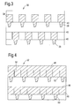
- Figure 3 shows appropriate locations of the masking material 38 for the first internal membrane leaf 30 that is intended to be bonded against the first outer wall 16 of the aerofoil.
- the surface to which the yttria is applied is the surface facing away from the first outer wall 16 with the selected locations corresponding to positions that will ultimately underlie the finger 34.
- the fingers, which are part of the second sheet of titanium, will therefore be free to lift and separate from the first membrane leaf.
- a second membrane leaf 32 is laminated to the first membrane leaf.
- This second membrane leaf has a thickness similar to the first membrane leaf and, although not strictly necessary to manufacture the fingers of Figure 2 , may have a selectively applied coating of yttria or other masking material applied to the face of the membrane leaf 32 facing the first membrane 30.
- an yttria coating is desired on the upper surface of the second internal membrane leaf 32 i.e. the surface facing away from the first membrane leaf 30 to permit the finger 34 to be shaped.
- this may be applied to the membrane leaf 32 before the membrane leaf 32 is laminated to the first membrane leaf 30 it is desirable to wait till the membranes have been joined as the first membrane leaf 30 can be used as a datum to ensure that the masking material is applied to the correct location on the second leaf.
- the yttria may be applied over a greater surface area than required to correspond to the fingers in order to improve the manufacturability of the blade.
- the remaining area may be masked by yttria to reduce the requirement to exactly locate the masking material. Manufacturing tolerance is thereby improved.
- the inner membranes 30, 32 may be laminated and secured together by either temporary of permanent means.
- Temporary means include techniques such as clamping or tack welding which are intended to secure the membranes till they are permanently joined by diffusion bonding.
- each sheet is cut along a different profile.
- Laser cutting is preferred because it offers a simple, controllable process that offers good accuracy. However, other techniques may be applicable.
- From the underside of the laminate 30 the laser cuts along lines 40 of Figure 3 to a depth equal to the depth of the first sheet.
- the second sheet 32 is uncut. If desired a series of perforations may be made at selected locations rather than a clean cut. The perforations separate when the blade is inflated but are sufficient to maintain the integrity of the laminated membrane before the outer walls are joined.
- This cut is intended to separate the lower intermediate membrane leaf 30 into a plurality of segments denoted 30' and 30" in Figure 2 .
- the first segment 30' is intended to be secured to the outer wall 16 whilst the second segment 30" is intended to be bonded to the upper intermediate membrane leaf 32 which, in turn, is bonded to the other outer wall. In this way, when the blade is later inflated the two segments 30', 30" are separated towards the opposite outer walls of the inflated blade.
- the second membrane leaf 32 is then cut from the opposite surface of the laminate to form the finger profiles and to divide the membrane into a plurality of segments. It is desirable that the cut depth is equal to the depth of the membrane leaf 32, though a slight cut through into the first membrane leaf may be acceptable provided the whole depth of the first membrane is not cut through.
- perforations may be used to maintain the integrity of the laminate before the outer panels are joined.
- the first outer wall 16 intended to be joined to the first membrane leaf 30 is prepared with a coating of yttria at selected locations as shown in Figure 5 .
- the locations permit the first leaf to divide on inflation into regions with one region 30' being firmly attached to the outer wall and the other region 30" being pulled by the second membrane leaf 32 to the second outer wall of the article.
- the region 30" corresponds to the masked and coated areas 54.
- the second outer wall shown in Figure 6 , is laminated directly to the exposed surface of the second inner membrane leaf 32.
- yttria is applied to all the necessary locations where it is undesirable to stick the membrane by applying the coating directly to the second internal membrane leaf 32 as discussed with reference to Figure 4 .
- the four sheet laminate is diffusion bonded and the resulting diffusion bonded laminate is arranged in a die and subjected to super plastic forming operations.
- the die and the laminate are subjected to heating to a super plastic temperature for the material in question.
- the material is titanium which exhibits super plasticity at a temperature around 850°C.
- an inert gas typically argon, is injected at high pressure into the interior of the blade. At the elevated temperatures the high pressure gas pushes the panels 16, 18 apart stretching and separating the internal membranes.
- the laminate is allowed to continue to extend by moving apart the panels 16, 18 until the panels contact the surfaces of the opposing die plates.
- the blade subassembly is allowed to cool and is arranged in a second die which has opposing surfaces which are formed as a female die formation for the ultimate exterior shape of the panels.
- the subassembly is then subject to a hot forming process in which, again, the die and the subassembly is heated to a hot forming temperature, for titanium normally around 750°C.
- the inert gas is injected into the interior of the subassembly at high pressure, around 30bar.
- the panels move apart but because the titanium is not at a superplastic temperature the internal fingers do not stretch but instead bend and slide to form spring elements.
- the internal pressure is applied until the panels 16, 18 have assumed their final shapes.
- the fan blade is then removed from the die and cooled.
- the inflation process separates portions of the first and second membrane leafs depending on where they are attached to the outer walls.
- the first inner membrane has been cut into two regions 30', 30".
- the first section 30' is diffusion bonded to the outer wall 16 and remains attached when the blade is inflated.
- the second section 30" overlies an yttria coating and is not attached to the outer wall.
- the second section 30" is diffusion bonded to the second inner membrane 32 which is bonded to the second outer wall 18 inflation of the blade causes the second section to move away from the lower wall 16 to leave a void or cavity 19.
- the second region 30", 32" moves relative to the first region 30', 32' in a direction perpendicular to the plane of the membranes.
- the finger is attached at its proximal end to the first region 30',32' and whilst it is not joined at its distal end to the second section 30", 32" the tip of the finger is trapped between the inner membrane leaf 30" and the outer wall 18 and is pulled upwards. The distal end is permitted to slide within the cavity 60 formed between the outer wall and the membrane to reduce stress within the blade.
- the finger is flexibly mounted to provide a "soft" connection between the two faces as opposed to a rigid connection and this helps to reduce the level of modal cross-talk between the two faces.
- the distal tip of the finger has a shaped taper. Initially, before the blade is inflated the tip engages the end of the recess 60. As the blade is inflated using a blow forming or super plastic forming process the tip is retracted from the end of the recess. The disengaged tip is free to slide within the slot in two dimensions i.e. towards or away from the end of the recess or side to side within the recess. It will be appreciated that where only fore and aft movement is required the finger may be provided without a tapered end.
- a hole is formed in one of the outer panels and a visco-elastic material introduced in a conventional manner.
- the material fills the whole of the cavity 19 with the fingers inhibiting radial movement of the damping material when the blade is in use within the gas turbine engine.
- the arrangement of the fingers and the spacing between fingers both within the rows and between adjacent rows is determined in part by the visco-elastic material being used within the blade.
- Each of the fingers and the rows must be spaced from one another a distance that is sufficient to permit the visco-elastic material to flow past them on filling, yet close enough to inhibit flow of the visco-elastic material once the blade is in use.
- the size and geometry of the blade will also have a bearing on the number of rows of fingers up the blade and their spacing and the number and spacing of the fingers within each row.
- the number of fingers within each row may be the same or different and they may be offset from or in line with fingers within adjacent rows depending on design choice.
- These so-called “reverse fingers” may be arranged to different curve arrangement to the fingers depicted in figure 2 leading to a beneficial effect on the retention of the visco-elastic filler.
- the different curve direction may be arranged to have the concave surface facing in the opposite direction i.e. towards the tip rather than towards the root as shown in figure 2 .
- the concave surface of the "reverse fingers” may also face towards the root but, because the secured proximal end is on the opposing wall to the secured proximal end of the normal fingers, the curve arrangement is different.
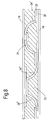
- Such an arrangement is shown in Figure 8 where fingers 34', 34" and 34"' show possible orientations in relation to the finger 34 of Figure 2 .
- the visco-elastic filler 70 fills the cavity 19.
- the panels 16, 18 and the internal membranes may all be titanium, or they may be formed of different materials.
- the blade is relatively easy to manufacture using known manufacturing processes such as diffusion bonding and super plastic forming.
- the internal architecture fits into a small cavity geometry and can be manufactured using layers which means there is minimal collapse at the diffusion bonding stage.
- the internal architecture as described retains visco-elastic material during centrifugal loadings with a good barrier shape.
- the form pattern can be easily tailored for specific design architecture to provide the optimum internal arrangement.
- blades for open-rotor and propeller structures for example turbo prop, ducted and unducted fans and other turbomachinery
- the invention may also have application for static aerofoil structures and non-aerofoil components, such as blade containment structures for gas turbine engines.
- the invention may also find application in fields away from aerospace for example for components such as hollow manufacturing machinery where the machinery is subject to significant vibration and damping is required.
Landscapes
- Engineering & Computer Science (AREA)
- Mechanical Engineering (AREA)
- General Engineering & Computer Science (AREA)
- Physics & Mathematics (AREA)
- Fluid Mechanics (AREA)
- Laminated Bodies (AREA)
- Turbine Rotor Nozzle Sealing (AREA)
Abstract
Description
- This invention relates to an article with an internal structure which may also have a damping filler. The invention is particularly, although not exclusively, useful where the article is a rotatable article such as a blade for use in a gas turbine engine.
- It is known to use hollow aerofoils on gas turbine engine fan blades. The hollow aerofoil is typically formed by inflating a blade pre-cursor at a temperature where the blade exhibits superplasticity and is often provided with a rigid internal metallic structure to increase strength and prevent so called panting of the walls of the aerofoil i.e. movement towards and away from each other.
- It has been found that rigid structures can transmit vibrations across the blade that increase the modal response of the blade which ultimately, in severe cases, can lead to failure of the blade earlier in its lifetime than desired.
- To facilitate damping and reduce vibration of the component the hollow cavity can be filled with a damping material. The damping material should be capable of resisting shear loading at the operating temperature of the article. A particularly useful, but still exemplary damping material is a visco-elastic material. In
GB2450934 - The rheostatic nature of visco-elastic materials results in a tendency to flow when loaded in tension. For rotating aerofoils there is a requirement to retain the damping material during running to prevent, or at least resist movement of the damping media during operation of the engine.
- There is also a requirement to simplify the manufacture of hollow blades with visco-elastic material retaining structures.
- It is an object of the present invention to seek to address these and other problems.
- According to a first aspect of the invention there is provided an article having first and second panels spaced apart from each other to provide a cavity, the first panel having at least one protrusion extending therefrom within the cavity towards the second panel, characterised in that the protrusion has a proximal end and a distal end, wherein the proximal end is secured to the first panel and the distal end is slidably secured in a pocket in the second panel.
- The first panel may comprise a laminate of an exterior wall and at least one interior membrane leaf, wherein the proximal end of the protrusion is integral with the interior membrane leaf(s).
- The second panel may comprise a laminate of an exterior wall and at least one interior membrane leaf, wherein the pocket is provided between the exterior wall and at least one of the interior membrane leafs.
- Preferably the membrane leafs are arranged as a laminate having outer surfaces wherein each outer surface is rigidly attached to either the first panel or the second panel at one or more regions thereof.
- The protrusions may be bowed. The distal end of the protrusion may be tapered.
- The first and second panels may be shaped to present a profile that generates lift from a fluid flowing past the article. The article may be an aerofoil or hydrofoil.
- The cavity may contain a damping material, which may be a viscoelastic damping material.
- The article may comprise a plurality of protrusions arranged as at least one array wherein the direction in which each array extends provides a barrier for inhibiting the passage of damping material in use when the cavity contains such material.
- The second panel may comprise a laminate of an exterior wall and at least one interior membrane, wherein the distal end of the protrusion is slidably mounted between the exterior wall and the interior membrane.
- The at least one protrusion may be slanted between the first and second panels.
- Preferably, at least some damping function is afforded by the contact sliding of the at least one protrusion on the second panel in addition to damping afforded by flexing of the viscoelastic material.
- If the article is exposed to centrifugal loads, preferably the direction of slant is opposite to the direction the damping material is moved under the centrifugal load in use. The article may comprise a plurality of protrusions arranged as an array wherein the direction in which the array extends is perpendicular to the direction of slant. Each array may be spaced from an adjacent array in the direction of slant of the protrusions.
- There may also be provided an article having first and second panels spaced apart from each other to provide a cavity, the cavity containing a damping material the first panel having at least one protrusion extending therefrom within the cavity towards the second panel, the protrusion having a proximal end and a distal end, wherein the proximal end is secured to the first panel and the distal end is slidably mounted to the second panel.
- According to a second aspect there is provided a method of manufacturing an article, the method comprising the steps of providing first and second panels, the first and second panels being secured together as a unit, wherein the first and second panels are separated to provide a cavity and a protrusion having a proximal end and a distal end, wherein the proximal end is secured to the first panel and the distal end is slidably secured in a pocket provided in the second panel.
- The unit may comprise a laminate of n membrane leafs where n>=2 between the first and second panels the membranes leafs being cut and having an application of stop-off material for preventing the adhesion of the membranes to the panels and each other at selected locations, wherein the protrusion is provided by a portion of n-x of the membrane leafs where x<=n-1.
- The laminate may have outer surfaces wherein each outer surface is rigidly attached to either the first panel or the second panel at one or more regions thereof.
- Preferably the first and second panels are moved apart following assembly into a unit.
- The first and second panels may be assembled into a unit by a process of diffusion bonding.
- Preferably the panels are moved apart by inserting a gas at high pressure therebetween to inflate the article.
- Preferably the method further comprising the step of injecting a viscoelastic damping material into the cavity.
- There may also be provided a method of manufacturing an article, the method comprising the steps of providing first and second panels, the first and second panels being secured together as a unit, wherein the first and second panels are separated to provide a cavity and a protrusion having a proximal end and a distal end, wherein the proximal end is secured to the first panel and the distal end is slidably mounted to the second panel.
- The unit may further comprise a laminate of first and second membranes between the first and second panels the membranes being cut and having an application of stop-off material for preventing the adhesion of the membranes to the panels and each other at selected locations, wherein the protrusion is provided by a portion of the second membrane.
- Preferably the distal end of the protrusion is slibably mounted between the second panel and the first membrane.
- Regions of the first membrane may be rigidly attached to the first panel and regions of the second membrane are rigidly attached to the second panel.
- Preferably the first and second panels are separated following assembly into a unit. The first and second panels may be assembled into a unit by a process of diffusion bonding.
- Preferably the panels are separated by inserting a gas at high pressure therebetween to inflate the article.
- A damping material may be injected into the cavity. Preferably the damping material has viscoelastic properties.
- The method may comprise the steps of providing first and second panels and first and second membranes between the first and second panels the membranes and panels being secured together as a unit with a first side of the first membrane secured to the first panel at a first set of selected locations, the second side of the first membrane being secured to a first side of the second membrane at a second set of selected locations, the second side of the second membrane being secured to the second panel at a third set of selected locations, wherein the first and second panels are moved apart such that the second membrane provides a protrusion with a proximal end and a distal end slidingly secured between the first membrane and the second panel.
- Embodiments of the invention will now be described by way of example only, with reference to the accompanying drawings. Where appropriate features shown in one embodiment may be interchanged with or added to features in another embodiment.
-
Fig. 1 is a perspective view of disk and blade body for a gas turbine in accordance with the invention. -
Fig. 2 depicts an exemplary arrangement of protrusions in the blade ofFig. 1 -
Fig. 3 depicts a pattern of stop-off material and location of cuts on a first surface of a first membrane leaf within the blade ofFig 1 . -
Fig. 4 depicts a pattern of stop-off material and location of cuts on a first surface of a second membrane leaf within the blade ofFig 1 . -
Fig. 5 depicts a pattern of stop-off material and location of cuts on the internal surface of an outer panel of the blade ofFig 1 . -
Fig. 6 depicts a pattern of stop-off material and location of cuts on the internal surface of an outer panel of the blade ofFig 1 . -
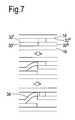
Fig. 7 depicts an inflation procedure of the blade ofFig. 1 -
Fig. 8 depicts alternative protrusion / finger arrangements for a blade. - In
Fig. 1 , ablisk 10 comprises adisk 12 andfan blade body 14. The blade body comprises first andsecond panels Fig. 2 ) therebetween. Between the first andsecond panels elongate ribs - The
void 19 is filled with a visco-elastic damping material. By way of non limiting example, the damping material may be a Huntsman™ syntactic damping paste or some such similar product. The damping material is of known composition and acts to inhibit vibration. - Although
Fig. 1 shows an exemplary arrangement of ribs it will be appreciated that as the blade rotates the generally parallel nature of the ribs will maximise strength of the tip against impact, e.g. bird strike as well as acting as a dam or barrier to prevent the visco-elastic material 24 from overloading and/or escaping the tip. Other rib configurations are envisaged and could be designed to maximise damping from specific mode shapes. - Each of the ribs is formed from a plurality of discrete fingers or protrusions spaced apart from each other and provided by an interior membrane preferably formed as a laminate of membrane leafs. One end of each finger is rigidly secured to one wall of the blade whilst the other end of the finger is flexibly mounted to the other wall of the blade. The finger resiliently extends between two outer walls of the blade to limit the transfer of vibrations between the walls whilst inhibiting panting of the blade.
-
Figure 2 shows an exemplary finger in one of therows wall 18 of theblade 14 has been removed for clarity. This wall would be bonded to portions of the top of theupper membrane leaf 32. - The
finger 34 has a proximal and a distal end. The proximal end of the finger is blended into the lower membrane leaf at the lower wall of the aerofoil whilst the distal end is not secured tomembrane leaf 32 but slidably secured between thelower membrane leaf 30 and the upper wall of theaerofoil 18. Thefingers 34 are defined by cutting out an appropriate shape from the membranes. - The manufacturing method will be described with reference to
Figures 3 to 7 . - A hollow fan blade in accordance with the invention is manufactured through a process of diffusion bonding and super plastic forming. A series of sheets formed of a diffusion bondable titanium alloy are laminated and heated to a temperature where the alloy exhibits superplasticity for a period of time sufficient to join the sheets together.
- To avoid the sheets bonding over their whole surface it is known to apply a ceramic yttria coating to selected locations. The coating prevents the sheets bonding where it is applied.
- Four sheets are required to manufacture the fingers shown in
Figure 2 . Thefirst sheet 16 provides one of the outer walls of the blade. Asecond sheet 18 provides the opposing outer wall of the blade. Twointernal membranes - In practice the blade is assembled in a several stage process. The
internal membranes - To manufacture the laminated internal membrane a
first sheet 30 of titanium alloy is masked and a coating of yttria applied to selected locations. The thickness of the sheet is less than that of the outer walls orpanels Figure 3 shows appropriate locations of the maskingmaterial 38 for the firstinternal membrane leaf 30 that is intended to be bonded against the firstouter wall 16 of the aerofoil. The surface to which the yttria is applied is the surface facing away from the firstouter wall 16 with the selected locations corresponding to positions that will ultimately underlie thefinger 34. The fingers, which are part of the second sheet of titanium, will therefore be free to lift and separate from the first membrane leaf. - A
second membrane leaf 32 is laminated to the first membrane leaf. This second membrane leaf has a thickness similar to the first membrane leaf and, although not strictly necessary to manufacture the fingers ofFigure 2 , may have a selectively applied coating of yttria or other masking material applied to the face of themembrane leaf 32 facing thefirst membrane 30. - As shown in
Figure 4 , an yttria coating is desired on the upper surface of the secondinternal membrane leaf 32 i.e. the surface facing away from thefirst membrane leaf 30 to permit thefinger 34 to be shaped. Although this may be applied to themembrane leaf 32 before themembrane leaf 32 is laminated to thefirst membrane leaf 30 it is desirable to wait till the membranes have been joined as thefirst membrane leaf 30 can be used as a datum to ensure that the masking material is applied to the correct location on the second leaf. - However, it will be appreciated that the yttria may be applied over a greater surface area than required to correspond to the fingers in order to improve the manufacturability of the blade. Provided there is a sufficient area of the membranes let uncoated to ensure good adhesion between the membranes and the membranes and the outer walls in the desired locations then the remaining area may be masked by yttria to reduce the requirement to exactly locate the masking material. Manufacturing tolerance is thereby improved.
- The
inner membranes - Once the laminate of the two
inner membranes lines 40 ofFigure 3 to a depth equal to the depth of the first sheet. Thesecond sheet 32 is uncut. If desired a series of perforations may be made at selected locations rather than a clean cut. The perforations separate when the blade is inflated but are sufficient to maintain the integrity of the laminated membrane before the outer walls are joined. - This cut is intended to separate the lower
intermediate membrane leaf 30 into a plurality of segments denoted 30' and 30" inFigure 2 . The first segment 30' is intended to be secured to theouter wall 16 whilst thesecond segment 30" is intended to be bonded to the upperintermediate membrane leaf 32 which, in turn, is bonded to the other outer wall. In this way, when the blade is later inflated the twosegments 30', 30" are separated towards the opposite outer walls of the inflated blade. - The
second membrane leaf 32, as shown inFigure 4 , is then cut from the opposite surface of the laminate to form the finger profiles and to divide the membrane into a plurality of segments. It is desirable that the cut depth is equal to the depth of themembrane leaf 32, though a slight cut through into the first membrane leaf may be acceptable provided the whole depth of the first membrane is not cut through. Once again, perforations may be used to maintain the integrity of the laminate before the outer panels are joined. Alternatively, it is possible to cut each membrane leaf separately and laminate them together. The peripheries of the sheets are typically continuous and prevent the cuts causing the membranes from coming apart. Features may be provided to help align the sheets together. - The first
outer wall 16 intended to be joined to thefirst membrane leaf 30 is prepared with a coating of yttria at selected locations as shown inFigure 5 . The locations permit the first leaf to divide on inflation into regions with one region 30' being firmly attached to the outer wall and theother region 30" being pulled by thesecond membrane leaf 32 to the second outer wall of the article. Theregion 30" corresponds to the masked andcoated areas 54. - The second outer wall, shown in
Figure 6 , is laminated directly to the exposed surface of the secondinner membrane leaf 32. There is no explicit requirement to apply yttria to the underside of this sheet as yttria is applied to all the necessary locations where it is undesirable to stick the membrane by applying the coating directly to the secondinternal membrane leaf 32 as discussed with reference toFigure 4 . However, in certain circumstances, it may be desirable to apply the or an additional coating to the outer wall rather than or in addition to the coating on themembrane leaf 32. - Once the four sheet laminate is formed it is diffusion bonded and the resulting diffusion bonded laminate is arranged in a die and subjected to super plastic forming operations. The die and the laminate are subjected to heating to a super plastic temperature for the material in question. Generally the material is titanium which exhibits super plasticity at a temperature around 850°C. Then an inert gas, typically argon, is injected at high pressure into the interior of the blade. At the elevated temperatures the high pressure gas pushes the
panels panels - The blade subassembly is allowed to cool and is arranged in a second die which has opposing surfaces which are formed as a female die formation for the ultimate exterior shape of the panels. The subassembly is then subject to a hot forming process in which, again, the die and the subassembly is heated to a hot forming temperature, for titanium normally around 750°C. The inert gas is injected into the interior of the subassembly at high pressure, around 30bar. The panels move apart but because the titanium is not at a superplastic temperature the internal fingers do not stretch but instead bend and slide to form spring elements.
- The internal pressure is applied until the
panels - The inflation process separates portions of the first and second membrane leafs depending on where they are attached to the outer walls. Referring back to
Figure 2 , the first inner membrane has been cut into tworegions 30', 30". The first section 30' is diffusion bonded to theouter wall 16 and remains attached when the blade is inflated. Thesecond section 30" overlies an yttria coating and is not attached to the outer wall. However, since thesecond section 30" is diffusion bonded to the secondinner membrane 32 which is bonded to the secondouter wall 18 inflation of the blade causes the second section to move away from thelower wall 16 to leave a void orcavity 19. - When the blade is inflated the
second region 30", 32" moves relative to the first region 30', 32' in a direction perpendicular to the plane of the membranes. The finger is attached at its proximal end to the first region 30',32' and whilst it is not joined at its distal end to thesecond section 30", 32" the tip of the finger is trapped between theinner membrane leaf 30" and theouter wall 18 and is pulled upwards. The distal end is permitted to slide within thecavity 60 formed between the outer wall and the membrane to reduce stress within the blade. The finger is flexibly mounted to provide a "soft" connection between the two faces as opposed to a rigid connection and this helps to reduce the level of modal cross-talk between the two faces. - The distal tip of the finger has a shaped taper. Initially, before the blade is inflated the tip engages the end of the
recess 60. As the blade is inflated using a blow forming or super plastic forming process the tip is retracted from the end of the recess. The disengaged tip is free to slide within the slot in two dimensions i.e. towards or away from the end of the recess or side to side within the recess. It will be appreciated that where only fore and aft movement is required the finger may be provided without a tapered end. - A hole is formed in one of the outer panels and a visco-elastic material introduced in a conventional manner. The material fills the whole of the
cavity 19 with the fingers inhibiting radial movement of the damping material when the blade is in use within the gas turbine engine. - The arrangement of the fingers and the spacing between fingers both within the rows and between adjacent rows is determined in part by the visco-elastic material being used within the blade. Each of the fingers and the rows must be spaced from one another a distance that is sufficient to permit the visco-elastic material to flow past them on filling, yet close enough to inhibit flow of the visco-elastic material once the blade is in use.
- Once the visco-elastic damping material has been added the hole through which it is inserted is closed.
- It will be appreciated that the size and geometry of the blade will also have a bearing on the number of rows of fingers up the blade and their spacing and the number and spacing of the fingers within each row.
- The number of fingers within each row may be the same or different and they may be offset from or in line with fingers within adjacent rows depending on design choice.
- It has been mentioned earlier in the specification that a coating may be applied to the underside of the second intermediate sheet this is of particular benefit where it is desired to form "reverse fingers", or fingers that have their proximal ends attached to the first
intermediate sheet 30 and their distal ends interlocked between the secondintermediate sheet 32 and the lowerouter wall 16. - These so-called "reverse fingers" may be arranged to different curve arrangement to the fingers depicted in
figure 2 leading to a beneficial effect on the retention of the visco-elastic filler. The different curve direction may be arranged to have the concave surface facing in the opposite direction i.e. towards the tip rather than towards the root as shown infigure 2 . Alternatively, the concave surface of the "reverse fingers" may also face towards the root but, because the secured proximal end is on the opposing wall to the secured proximal end of the normal fingers, the curve arrangement is different. Such an arrangement is shown inFigure 8 wherefingers 34', 34" and 34"' show possible orientations in relation to thefinger 34 ofFigure 2 . The visco-elastic filler 70 fills thecavity 19. - The
panels - It is also possible to combine the sliding fingers or protrusions in an array with one or more connections that are rigidly secured to both outer walls of the article. Although the rigid connection may increase cross-talk between the panels judicious use of their location may provide beneficial effects such as reduced twisting of the article.
- It will be appreciated that the present invention offers a number of significant advantages. For example, the blade is relatively easy to manufacture using known manufacturing processes such as diffusion bonding and super plastic forming. The internal architecture fits into a small cavity geometry and can be manufactured using layers which means there is minimal collapse at the diffusion bonding stage. The internal architecture as described retains visco-elastic material during centrifugal loadings with a good barrier shape. Beneficially, the form pattern can be easily tailored for specific design architecture to provide the optimum internal arrangement.
- Although we have described the application of the above invention to a fan blade, it is envisaged that any suitable hollow structure could use the present invention. For example, blades for open-rotor and propeller structures (for example turbo prop, ducted and unducted fans and other turbomachinery)could be manufactured to have similar structures to those described above. The invention may also have application for static aerofoil structures and non-aerofoil components, such as blade containment structures for gas turbine engines.
- The invention may also find application in fields away from aerospace for example for components such as hollow manufacturing machinery where the machinery is subject to significant vibration and damping is required.
Claims (17)
- An article having first and second panels spaced apart from each other to provide a cavity (19), the first panel having at least one protrusion (34) extending therefrom within the cavity towards the second panel, characterised in that the protrusion has a proximal end and a distal end, wherein the proximal end is secured to the first panel and the distal end is slidably secured in a pocket (60) in the second panel.
- An article according to claim 1, wherein the first panel comprises a laminate of an exterior wall (16) and at least one interior membrane leaf (30',32), wherein the proximal end of the protrusion is integral with the interior membrane leaf(s).
- An article according to claim 1 or claim 2, wherein the second panel comprises a laminate of an exterior wall (18) and at least one interior membrane leaf (30",32"), wherein the pocket is provided between the exterior wall (18) and at least one of the interior membrane leafs (30",32").
- An article according to claim 2 or claim 3, wherein the membrane leafs are arranged as a laminate having outer surfaces wherein each outer surface is rigidly attached to either the first panel or the second panel at one or more regions thereof.
- An article according to any preceding claim, wherein the protrusions are bowed.
- An article according to any preceding claim, wherein the distal end of the protrusion is tapered.
- An article according to any preceding claim, wherein the first and second panels are shaped to present a profile that generates lift from a fluid flowing past the article.
- An article according to any preceding claim, wherein the cavity contains a damping material.
- An article according to claim 8, wherein the damping material is a viscoelastic damping material.
- An article according to any preceding claim, comprising a plurality of protrusionss arranged as at least one array wherein the direction in which each array extends provides a barrier for inhibiting the passage of damping material when the cavity contains such material.
- A method of manufacturing an article, the method comprising the steps of providing first and second panels, the first and second panels being secured together as a unit, wherein the first and second panels are separated to provide a cavity (19) and at least one protrusion (34) having a proximal end and a distal end, wherein the proximal end is secured to the first panel and the distal end is slidably secured in a pocket (60) provided in the second panel.
- A method according to claim 11, wherein the unit further comprises a laminate of n membrane leafs where n>=2 between the first and second panels the membranes leafs being cut and having an application of stop-off material for preventing the adhesion of the membranes to the panels and each other at selected locations, wherein the protrusion is provided by a portion of n-x of the membrane leafs where x<=n-1.
- A method according to claim 11 or claim 12, wherein the laminate has outer surfaces wherein each outer surface is rigidly attached to either the first panel or the second panel at one or more regions thereof.
- A method according to any of claim 11 to claim 13, wherein the first and second panels are moved apart following assembly into a unit.
- A method according to claim 14, wherein the first and second panels are assembled into a unit by a process of diffusion bonding.
- A method according to claim 14, wherein the panels are moved apart by inserting a gas at high pressure therebetween to inflate the article.
- A method according to any of claims 11 to 16, further comprising the step of injecting a viscoelastic damping material (70) into the cavity.
Applications Claiming Priority (1)
| Application Number | Priority Date | Filing Date | Title |
|---|---|---|---|
| GBGB0901235.2A GB0901235D0 (en) | 2009-01-27 | 2009-01-27 | An article with a filler |
Publications (1)
| Publication Number | Publication Date |
|---|---|
| EP2210683A1 true EP2210683A1 (en) | 2010-07-28 |
Family
ID=40469082
Family Applications (1)
| Application Number | Title | Priority Date | Filing Date |
|---|---|---|---|
| EP20090252779 Withdrawn EP2210683A1 (en) | 2009-01-27 | 2009-12-14 | An article with an internal structure |
Country Status (3)
| Country | Link |
|---|---|
| US (1) | US8920893B2 (en) |
| EP (1) | EP2210683A1 (en) |
| GB (1) | GB0901235D0 (en) |
Cited By (2)
| Publication number | Priority date | Publication date | Assignee | Title |
|---|---|---|---|---|
| EP3055096A4 (en) * | 2013-10-09 | 2017-08-30 | United Technologies Corporation | Method and system for diffusion bonded components having internal passages |
| US10569321B2 (en) | 2014-11-28 | 2020-02-25 | Repkon Machine and Tool Industry and Trade Inc. | Device and method for flow-forming workpieces |
Families Citing this family (6)
| Publication number | Priority date | Publication date | Assignee | Title |
|---|---|---|---|---|
| US8727714B2 (en) * | 2011-04-27 | 2014-05-20 | Siemens Energy, Inc. | Method of forming a multi-panel outer wall of a component for use in a gas turbine engine |
| US10301948B2 (en) | 2013-03-14 | 2019-05-28 | United Technologies Corporation | Fan blade damping device |
| FR3041401B1 (en) * | 2015-09-21 | 2017-09-29 | Snecma | SHOCK ABSORBER ASSEMBLY FOR HYDRAULIC AND ELECTRICAL CONNECTION OF A NON-CARBENE BLOWER |
| JP6801973B2 (en) * | 2016-03-24 | 2020-12-16 | 三菱パワー株式会社 | Rotating machine wings and rotating machinery |
| US10801329B2 (en) | 2017-11-17 | 2020-10-13 | General Electric Company | Vibration-damping components, gas turbine engine and method of forming such components |
| US10858945B2 (en) | 2018-01-12 | 2020-12-08 | United Technologies Corporation | Apparatus and method for selective bonding to form hollow components |
Citations (7)
| Publication number | Priority date | Publication date | Assignee | Title |
|---|---|---|---|---|
| US5119531A (en) * | 1988-02-26 | 1992-06-09 | Michel Berger | System for joining by interengagement comprising interengaging elements formed by ridges with elastically deformable lips, in particular curvilinear |
| US5419039A (en) * | 1990-07-09 | 1995-05-30 | United Technologies Corporation | Method of making an air cooled vane with film cooling pocket construction |
| GB2397855A (en) * | 2003-01-30 | 2004-08-04 | Rolls Royce Plc | Damping vibrations in turbomachine aerofoils |
| GB2401407A (en) * | 2003-05-03 | 2004-11-10 | Rolls Royce Plc | a hollow component with internal vibration damping |
| US20080025846A1 (en) * | 2006-07-27 | 2008-01-31 | Siemens Power Generation, Inc. | Hollow CMC airfoil with internal stitch |
| US20080260538A1 (en) * | 2003-03-12 | 2008-10-23 | Florida Turbine Technologies, Inc. | Spar and shell constructed turbine blade |
| GB2450934A (en) | 2007-07-13 | 2009-01-14 | Rolls Royce Plc | A component with a damping filler |
Family Cites Families (132)
| Publication number | Priority date | Publication date | Assignee | Title |
|---|---|---|---|---|
| US2202014A (en) * | 1938-02-10 | 1940-05-28 | Lougheed Victor | Air propeller blade and material for making same |
| GB859202A (en) * | 1956-08-30 | 1961-01-18 | Babcock & Wilcox Ltd | Improvements in nuclear reactors and in or relating to nuclear reactor fuel elements |
| GB842937A (en) | 1957-09-03 | 1960-07-27 | George Mountford Adie | Improvements in and relating to materials for use in the construction of buildings |
| US3111747A (en) | 1959-06-30 | 1963-11-26 | Olin Mathieson | Hollow articles |
| US3630240A (en) | 1969-09-18 | 1971-12-28 | Essex International Inc | Winding and transfer apparatus for dynamoelectric machine stator coils |
| FR2112116B1 (en) | 1970-11-05 | 1973-08-10 | Commissariat Energie Atomique | |
| US3736638A (en) * | 1971-04-07 | 1973-06-05 | United Aircraft Corp | Method for bonding opposed parts of a hollow article together |
| FR2330276A5 (en) | 1973-12-05 | 1977-05-27 | United Aircraft Corp | SHOCK ABSORBER FOR TURBINE BLADES |
| US3927817A (en) * | 1974-10-03 | 1975-12-23 | Rockwell International Corp | Method for making metallic sandwich structures |
| US4217397A (en) * | 1978-04-18 | 1980-08-12 | Mcdonnell Douglas Corporation | Metallic sandwich structure and method of fabrication |
| US4304821A (en) * | 1978-04-18 | 1981-12-08 | Mcdonnell Douglas Corporation | Method of fabricating metallic sandwich structure |
| US4292375A (en) * | 1979-05-30 | 1981-09-29 | The United States Of America As Represented By The Administrator Of The National Aeronautics And Space Administration | Superplastically formed diffusion bonded metallic structure |
| US4331284A (en) * | 1980-03-14 | 1982-05-25 | Rockwell International Corporation | Method of making diffusion bonded and superplastically formed structures |
| US4361262A (en) | 1980-06-12 | 1982-11-30 | Rockwell International Corporation | Method of making expanded sandwich structures |
| US4583914A (en) * | 1982-06-14 | 1986-04-22 | United Technologies Corp. | Rotor blade for a rotary machine |
| US4522860A (en) * | 1983-01-10 | 1985-06-11 | Metalcore Limited | Material for reinforcing core in a structure |
| US4811890A (en) * | 1983-05-07 | 1989-03-14 | Rockwell International Corporation | Method of eliminating core distortion in diffusion bonded and uperplastically formed structures |
| US4530197A (en) * | 1983-06-29 | 1985-07-23 | Rockwell International Corporation | Thick core sandwich structures and method of fabrication thereof |
| US4594761A (en) | 1984-02-13 | 1986-06-17 | General Electric Company | Method of fabricating hollow composite airfoils |
| DE3405736A1 (en) * | 1984-02-17 | 1985-08-22 | Ipa-Isorast International S.A., Panama | FORMWORK ELEMENT FOR THE SHEATH CONCRETE CONSTRUCTION AND WARM INSULATION PANEL |
| GB8428064D0 (en) | 1984-11-06 | 1984-12-12 | British Aerospace | Forming complex hollow sectioned members |
| US4642863A (en) * | 1985-04-15 | 1987-02-17 | Ontario Technologies Corporation | Manufacturing method for hollow metal airfoil type structure |
| DE3680161D1 (en) | 1985-07-22 | 1991-08-14 | Matsushita Electric Industrial Co Ltd | ELECTRIC WATER HEATER. |
| GB8523933D0 (en) * | 1985-09-27 | 1985-10-30 | British Shipbuilders Eng | Large sandwich structures |
| GB2193306A (en) | 1986-04-29 | 1988-02-03 | Kenneth Higham | Electric heating systems |
| GB8623552D0 (en) | 1986-10-01 | 1986-11-05 | Davies B G | Temperature control system |
| GB2202619A (en) | 1987-03-24 | 1988-09-28 | Kenneth Higham | Electric heating systems |
| GB2206685A (en) | 1987-07-07 | 1989-01-11 | Paul Lenworth Mantock | Closed circuit water electric heating unit |
| GB2211593B (en) | 1987-10-24 | 1992-06-10 | Alan Nelson Middleton | Central heating convector radiator, water filled, heated by an electric element and having a power input cycling mode |
| US4882823A (en) * | 1988-01-27 | 1989-11-28 | Ontario Technologies Corp. | Superplastic forming diffusion bonding process |
| DE8809721U1 (en) | 1988-07-28 | 1988-09-29 | Kermi GmbH, 8350 Plattling | Connection set for radiators with electric heating element |
| GB8821222D0 (en) | 1988-09-09 | 1988-12-14 | British Aerospace | Double curvature structures by superplastic forming & diffusion bonding |
| GB2228069A (en) | 1989-01-04 | 1990-08-15 | Gledhill Water Storage | Control of the heat in a thermal store provided by a tank of water |
| FR2651869A1 (en) | 1989-09-14 | 1991-03-15 | Comparon Jean Daniel | ELECTRIC BOILER WITH CYCLONIC TURBULENCE. |
| EP0469221A1 (en) | 1990-07-31 | 1992-02-05 | Peter Hediger | Device for dissecting a workpiece |
| BR7002400U (en) | 1990-11-08 | 1992-07-07 | Jose Carlos Cella | CONSTRUCTIVE ARRANGEMENT FOR TRIAC IN SHOWERS OR PASSAGE HEATERS |
| GB2251063A (en) | 1990-12-20 | 1992-06-24 | John Anthony Page | Self contained liquid filled radiator |
| US5253419A (en) * | 1991-02-20 | 1993-10-19 | Societe Nationale D'etude Et De Construction De Moteurs D'aviation "S.N.E.C.M.A." | Method of manufacturing a hollow blade for a turboshaft engine |
| FR2672826B1 (en) | 1991-02-20 | 1995-04-21 | Snecma | PROCESS FOR MANUFACTURING A HOLLOW BLADE FOR A TURBOMACHINE. |
| US5420400A (en) * | 1991-10-15 | 1995-05-30 | The Boeing Company | Combined inductive heating cycle for sequential forming the brazing |
| CA2072239C (en) | 1991-06-27 | 1999-12-14 | Dipak J. Shah | Error based zone controller |
| DE69211069T2 (en) * | 1991-07-29 | 1996-10-02 | Rolls Royce & Ass | Compressed gas tank |
| US5240376A (en) * | 1991-07-31 | 1993-08-31 | Mcdonnell Douglas Corporation | SPF/DB hollow core fan blade |
| JP2808500B2 (en) | 1991-08-23 | 1998-10-08 | 三菱重工業株式会社 | Gas turbine hollow fan blades |
| US5243758A (en) * | 1991-12-09 | 1993-09-14 | General Electric Company | Design and processing method for manufacturing hollow airfoils (three-piece concept) |
| US5330092A (en) * | 1991-12-17 | 1994-07-19 | The Boeing Company | Multiple density sandwich structures and method of fabrication |
| DE9201770U1 (en) | 1992-02-12 | 1992-04-16 | Buderus Heiztechnik GmbH, 6330 Wetzlar | Device for receiving coded time signals transmitted by radio |
| DE4226468A1 (en) | 1992-08-10 | 1994-02-17 | Haschkamp Ernestine | Circuit arrangement for electric heaters |
| EP0594885B1 (en) | 1992-10-29 | 2000-03-15 | Landis & Gyr Technology Innovation AG | Method for controlling a heating system and device for carrying out the method |
| EP0594886B1 (en) | 1992-10-29 | 2001-07-18 | Landis & Gyr Technology Innovation AG | Method and controlling a heating system and device for carrying out the method |
| US5469618A (en) * | 1993-12-06 | 1995-11-28 | General Electric Company | Method for manufacturing hollow airfoils (two-piece concept) |
| FR2715883B1 (en) * | 1994-02-10 | 1996-03-29 | Snecma | Process for obtaining a circular metal part reinforced with fibers. |
| FR2728062A1 (en) | 1994-12-09 | 1996-06-14 | Sgs Thomson Microelectronics | HEATING SYSTEM COMPRISING A CONTROL UNIT AND RADIATORS PROVIDED WITH PRESENCE DETECTION MEANS |
| US5570552A (en) * | 1995-02-03 | 1996-11-05 | Nehring Alexander T | Universal wall forming system |
| GB9503622D0 (en) | 1995-02-23 | 1995-04-12 | Crampton Frederick A | Space heating apparatus |
| US5692881A (en) * | 1995-06-08 | 1997-12-02 | United Technologies Corporation | Hollow metallic structure and method of manufacture |
| FR2739045B1 (en) | 1995-09-27 | 1997-10-31 | Snecma | PROCESS FOR MANUFACTURING A HOLLOW BLADE OF A TURBOMACHINE |
| GB2305720B (en) | 1995-09-29 | 2000-01-26 | Tristat Controls Ltd | Water filled radiator heater |
| WO1997027045A2 (en) | 1996-01-12 | 1997-07-31 | The Boeing Company | Metal sandwich structure with integral hardpoint |
| ATE230855T1 (en) | 1996-03-12 | 2003-01-15 | Tyco Electronics Corp | ELECTRICAL HEATING SYSTEMS |
| JPH1054204A (en) * | 1996-05-20 | 1998-02-24 | General Electric Co <Ge> | Multi-component wing for gas turbine |
| US5723225A (en) * | 1996-08-26 | 1998-03-03 | Mcdonnell Douglas Corporation | Superplastically formed, diffusion bonded multiple sheet panels with web doublers and method of manufacture |
| US5820348A (en) * | 1996-09-17 | 1998-10-13 | Fricke; J. Robert | Damping system for vibrating members |
| US5881459A (en) * | 1996-09-27 | 1999-03-16 | Mcdonnell Douglas Corporation | Pressure communication for superplastically formed, diffusion bonded panels and method of manufacture |
| US5941446A (en) * | 1997-07-10 | 1999-08-24 | Mcdonnell Douglas Corporation | SPF/DB airfoil-shaped structure and method of fabrication thereof |
| CA2307471A1 (en) * | 1997-10-27 | 1999-05-06 | Siemens Westinghouse Power Corporation | Method of bonding cast superalloys |
| US6039542A (en) | 1997-12-24 | 2000-03-21 | General Electric Company | Panel damped hybrid blade |
| US6138898A (en) | 1998-12-22 | 2000-10-31 | The Boeing Company | Corner gap weld pattern for SPF core packs |
| FR2788842B1 (en) | 1999-01-27 | 2001-06-01 | Micrel | WATER CIRCULATION HEATING CONTROL DEVICE |
| US6220518B1 (en) | 1999-05-13 | 2001-04-24 | Acutherm L.P. | Process and apparatus for individual adjustment of the temperature set points of a plurality of VAV devices |
| FR2798458B1 (en) | 1999-09-15 | 2001-12-14 | Delta Dore | CONTROL DEVICE FOR A HEAT TRANSFER FLUID CIRCULATION SYSTEM |
| US6287080B1 (en) * | 1999-11-15 | 2001-09-11 | General Electric Company | Elastomeric formulation used in the construction of lightweight aircraft engine fan blades |
| DE19956444B4 (en) * | 1999-11-24 | 2004-08-26 | Mtu Aero Engines Gmbh | Process for the production of a lightweight component in composite construction |
| FR2804278B1 (en) | 2000-01-25 | 2006-08-04 | G C Technology | SEMICONDUCTOR POLYMER TEMPERATURE LIMITER AND HEATING APPARATUS INCLUDING SUCH LIMITER |
| US6454536B1 (en) | 2000-02-09 | 2002-09-24 | General Electric Company | Adhesion enhancers to promote bonds of improved strength between elastomers metals in lightweight aircraft fan blades |
| GB2360236B (en) * | 2000-03-18 | 2003-05-14 | Rolls Royce Plc | A method of manufacturing an article by diffusion bonding and superplastic forming |
| TW486734B (en) | 2000-04-20 | 2002-05-11 | Mks Instr Inc | Heater control system including satellite control units with integrated power supply and electronic temperature control |
| FR2809832B1 (en) | 2000-06-02 | 2003-06-06 | Delta Dore | METHOD FOR CONFIGURING A REMOTE CONTROL HEATING CONTROL DEVICE |
| FR2809853B1 (en) | 2000-06-02 | 2002-07-26 | Delta Dore | HIGH FREQUENCY WIRELESS TRANSMISSION METHOD FOR A REMOTELY CONTROLLED HEATING CONTROL DEVICE |
| JP4530495B2 (en) * | 2000-07-03 | 2010-08-25 | 富士重工業株式会社 | Method for integrally forming superplastic materials |
| US6986940B1 (en) * | 2000-07-27 | 2006-01-17 | General Electric Company | Fiber reinforced composite article, fiber member, and method for making |
| JP3852555B2 (en) | 2000-09-01 | 2006-11-29 | 三菱電機株式会社 | Thermal control device, spacecraft, and thermal control method |
| US6745085B2 (en) | 2000-12-15 | 2004-06-01 | Honeywell International Inc. | Fault-tolerant multi-node stage sequencer and method for energy systems |
| GB0100695D0 (en) * | 2001-01-11 | 2001-02-21 | Rolls Royce Plc | a turbomachine blade |
| EP1275748A3 (en) * | 2001-07-13 | 2004-01-07 | ALSTOM (Switzerland) Ltd | High temperature resistant coating with locally embedded protrusions and its application process |
| FI20011863A7 (en) | 2001-09-21 | 2003-03-22 | Flaekt Woods Ab | Method and apparatus for wirelessly controlling air handling equipment |
| FR2832212B1 (en) | 2001-11-13 | 2005-07-22 | Henri Louis Russi | HEAT PUMP RADIATOR |
| US7441615B2 (en) * | 2001-12-07 | 2008-10-28 | General Motors Corporation | Modular chassis with simplified body-attachment interface |
| BE1014570A4 (en) | 2002-01-11 | 2004-01-13 | Sonaca Sa | Method of manufacturing a structure and structure obtained fluted thereby. |
| US6699015B2 (en) * | 2002-02-19 | 2004-03-02 | The Boeing Company | Blades having coolant channels lined with a shape memory alloy and an associated fabrication method |
| GB2387669B (en) | 2002-04-16 | 2006-04-26 | Honeywell Control Syst | Improvements in temperature control systems |
| EP1499525A1 (en) * | 2002-04-29 | 2005-01-26 | Rolls-Royce Naval Marine, Inc. | Propeller |
| FR2839372B1 (en) | 2002-05-06 | 2005-01-07 | Martinez Thierry | ENERGY CONTROL AND MANAGEMENT SYSTEM |
| WO2004005831A1 (en) | 2002-07-09 | 2004-01-15 | Zexel Valeo Climate Control Corporation | Tube for heat exchanger |
| GB2391270B (en) * | 2002-07-26 | 2006-03-08 | Rolls Royce Plc | Turbomachine blade |
| GB2393498A (en) | 2002-09-26 | 2004-03-31 | Cqi Ct Glow | Remote controller for a boiler |
| FR2849488B1 (en) | 2002-12-26 | 2005-02-25 | Renault Sa | SENSITIVELY RIGID TUBE FOR HIGH PRESSURE CIRCUIT |
| DE10312373B3 (en) | 2003-03-20 | 2004-04-22 | Buderus Heiztechnik Gmbh | Operating method for room heating regulation has energy-saving operating mode combined with night-time operating phase initiated by time clock |
| DE10312668B3 (en) | 2003-03-21 | 2004-06-24 | Honeywell Ag Home And Building Control | Room temperature regulation system for centrally-heated building with verification of authorization of room device used for transmitting required room temperature values |
| GB2400055B (en) * | 2003-03-29 | 2006-01-11 | Rolls Royce Plc | A hollow component with internal damping |
| FR2853572B1 (en) | 2003-04-10 | 2005-05-27 | Snecma Moteurs | METHOD FOR MANUFACTURING A HOLLOW MECHANICAL WELDING-DIFFUSION MECHANICAL PIECE AND SUPERPLASTIC FORMING |
| CZ13445U1 (en) | 2003-05-14 | 2003-06-30 | Korado A. S. | Heating plate-like element for combined heating |
| GB2402716B (en) | 2003-06-10 | 2006-08-16 | Rolls Royce Plc | A damped aerofoil structure |
| KR100526824B1 (en) | 2003-06-23 | 2005-11-08 | 삼성전자주식회사 | Indoor environmental control system and method of controlling the same |
| PT1652408E (en) | 2003-07-30 | 2009-10-29 | Saint Gobain | Electric heating system |
| GB2405186B (en) * | 2003-08-20 | 2005-10-26 | Rolls Royce Plc | A component with internal damping |
| BE1015775A3 (en) | 2003-11-07 | 2005-08-02 | Defx S A | Radiator. |
| GB2408295A (en) | 2003-11-14 | 2005-05-25 | Rolls Royce Plc | An assembly with a plastic insert between two metal components |
| US7048175B2 (en) * | 2003-12-19 | 2006-05-23 | The Boeing Company | Friction welded structural assembly and preform and method for same |
| US7775452B2 (en) | 2004-01-07 | 2010-08-17 | Carrier Corporation | Serial communicating HVAC system |
| US7744008B2 (en) | 2004-01-08 | 2010-06-29 | Robertshaw Controls Company | System and method for reducing energy consumption by controlling a water heater and HVAC system via a thermostat and thermostat for use therewith |
| US7377450B2 (en) | 2004-01-20 | 2008-05-27 | Carrier Corporation | Control of multi-zone and multi-stage HVAC system |
| US7125225B2 (en) | 2004-02-04 | 2006-10-24 | United Technologies Corporation | Cooled rotor blade with vibration damping device |
| GB2411462B (en) | 2004-02-25 | 2008-10-08 | Basic Holdings | Heating devices |
| US7090464B2 (en) | 2004-07-13 | 2006-08-15 | General Electric Company | Methods and apparatus for assembling rotatable machines |
| DE602005000542T2 (en) * | 2004-09-29 | 2007-06-14 | Nissan Motor Co., Ltd., Yokohama | Preform, hydroforming and so produced product |
| US7180039B2 (en) | 2004-10-29 | 2007-02-20 | Osram Sylvania Inc. | Heater with burnout protection |
| US7247003B2 (en) * | 2004-12-02 | 2007-07-24 | Siemens Power Generation, Inc. | Stacked lamellate assembly |
| US7410342B2 (en) * | 2005-05-05 | 2008-08-12 | Florida Turbine Technologies, Inc. | Airfoil support |
| DK1754886T3 (en) * | 2005-08-17 | 2012-12-17 | Gen Electric | Rotor blade for a wind turbine |
| US7334997B2 (en) | 2005-09-16 | 2008-02-26 | General Electric Company | Hybrid blisk |
| US20070243408A1 (en) * | 2005-11-22 | 2007-10-18 | Straza George C P | Formed core sandwich structure and method and system for making same |
| GB0601220D0 (en) | 2006-01-21 | 2006-03-01 | Rolls Royce Plc | Aerofoils for gas turbine engines |
| GB2438185A (en) | 2006-05-17 | 2007-11-21 | Rolls Royce Plc | An apparatus for preventing ice accretion |
| GB2450935B (en) | 2007-07-13 | 2009-06-03 | Rolls Royce Plc | Component with internal damping |
| GB2450936B (en) | 2007-07-13 | 2010-01-20 | Rolls Royce Plc | Bladed rotor balancing |
| US7875537B2 (en) * | 2007-08-29 | 2011-01-25 | Cree, Inc. | High temperature ion implantation of nitride based HEMTs |
| GB0808840D0 (en) * | 2008-05-15 | 2008-06-18 | Rolls Royce Plc | A compound structure |
| GB2462102B (en) | 2008-07-24 | 2010-06-16 | Rolls Royce Plc | An aerofoil sub-assembly, an aerofoil and a method of making an aerofoil |
| US8240987B2 (en) * | 2008-08-15 | 2012-08-14 | United Technologies Corp. | Gas turbine engine systems involving baffle assemblies |
| GB0901318D0 (en) * | 2009-01-28 | 2009-03-11 | Rolls Royce Plc | A method of joining plates of material to form a structure |
| GB0903280D0 (en) * | 2009-02-27 | 2009-04-08 | Rolls Royce Plc | Method of manufacturing a blade |
-
2009
- 2009-01-27 GB GBGB0901235.2A patent/GB0901235D0/en not_active Ceased
- 2009-12-14 EP EP20090252779 patent/EP2210683A1/en not_active Withdrawn
- 2009-12-14 US US12/654,211 patent/US8920893B2/en not_active Expired - Fee Related
Patent Citations (8)
| Publication number | Priority date | Publication date | Assignee | Title |
|---|---|---|---|---|
| US5119531A (en) * | 1988-02-26 | 1992-06-09 | Michel Berger | System for joining by interengagement comprising interengaging elements formed by ridges with elastically deformable lips, in particular curvilinear |
| US5419039A (en) * | 1990-07-09 | 1995-05-30 | United Technologies Corporation | Method of making an air cooled vane with film cooling pocket construction |
| GB2397855A (en) * | 2003-01-30 | 2004-08-04 | Rolls Royce Plc | Damping vibrations in turbomachine aerofoils |
| US20080260538A1 (en) * | 2003-03-12 | 2008-10-23 | Florida Turbine Technologies, Inc. | Spar and shell constructed turbine blade |
| GB2401407A (en) * | 2003-05-03 | 2004-11-10 | Rolls Royce Plc | a hollow component with internal vibration damping |
| US20080025846A1 (en) * | 2006-07-27 | 2008-01-31 | Siemens Power Generation, Inc. | Hollow CMC airfoil with internal stitch |
| GB2450934A (en) | 2007-07-13 | 2009-01-14 | Rolls Royce Plc | A component with a damping filler |
| EP2014386A1 (en) * | 2007-07-13 | 2009-01-14 | Rolls-Royce plc | A component with a damping filler |
Cited By (2)
| Publication number | Priority date | Publication date | Assignee | Title |
|---|---|---|---|---|
| EP3055096A4 (en) * | 2013-10-09 | 2017-08-30 | United Technologies Corporation | Method and system for diffusion bonded components having internal passages |
| US10569321B2 (en) | 2014-11-28 | 2020-02-25 | Repkon Machine and Tool Industry and Trade Inc. | Device and method for flow-forming workpieces |
Also Published As
| Publication number | Publication date |
|---|---|
| US20100189933A1 (en) | 2010-07-29 |
| GB0901235D0 (en) | 2009-03-11 |
| US8920893B2 (en) | 2014-12-30 |
Similar Documents
| Publication | Publication Date | Title |
|---|---|---|
| US8920893B2 (en) | Article with an internal structure | |
| US7311500B2 (en) | Turbomachine blade | |
| EP2233239A2 (en) | A method of manufacturing a component comprising an internal structure | |
| EP2014384B1 (en) | Component with internal damping, precursor for forming such component and method for manufacturing the same | |
| US20100143097A1 (en) | Aerofoils for gas turbine engines | |
| EP2014388B1 (en) | Aerofoil for a turbomachine with a damping filler and method of manufacturing thereof | |
| EP2243929B1 (en) | Hybrid structure fan blade | |
| EP2663414B1 (en) | Method for the generative production of a component with an integrated damping element for a turbomachine, and a component produced in a generative manner with an integrated damping element for a turbomachine | |
| EP3017149B1 (en) | Airfoil, and method for manufacturing the same | |
| US10787914B2 (en) | CMC airfoil with monolithic ceramic core | |
| US8986490B2 (en) | Method of manufacturing a component | |
| EP3567220B1 (en) | Vane including internal radiant heat shield | |
| US8439647B2 (en) | Cooled turbine airfoil fabricated from sheet material | |
| US8365388B2 (en) | Method of joining plates of material to form a structure | |
| US8579181B2 (en) | Method of forming an internal structure in a hollow component | |
| EP1881158B1 (en) | Blades | |
| US8689440B2 (en) | Method of forming a hollow component with an internal structure | |
| US20190055849A1 (en) | Laminated airfoil for a gas turbine | |
| GB2529641A (en) | Cavity filled aerofoil | |
| EP2273069B1 (en) | A method of forming an internal structure within a hollow component | |
| EP2243570B1 (en) | A method of manufacturing a component comprising an internal structure such a component and turbomachine having such a component | |
| EP3048252A1 (en) | Fan blade |
Legal Events
| Date | Code | Title | Description |
|---|---|---|---|
| PUAI | Public reference made under article 153(3) epc to a published international application that has entered the european phase |
Free format text: ORIGINAL CODE: 0009012 |
|
| 17P | Request for examination filed |
Effective date: 20100614 |
|
| AK | Designated contracting states |
Kind code of ref document: A1 Designated state(s): AT BE BG CH CY CZ DE DK EE ES FI FR GB GR HR HU IE IS IT LI LT LU LV MC MK MT NL NO PL PT RO SE SI SK SM TR |
|
| AX | Request for extension of the european patent |
Extension state: AL BA RS |
|
| 17Q | First examination report despatched |
Effective date: 20150326 |
|
| RAP1 | Party data changed (applicant data changed or rights of an application transferred) |
Owner name: ROLLS-ROYCE PLC |
|
| STAA | Information on the status of an ep patent application or granted ep patent |
Free format text: STATUS: THE APPLICATION IS DEEMED TO BE WITHDRAWN |
|
| 18D | Application deemed to be withdrawn |
Effective date: 20150806 |