EP2210370B1 - Procédé et composant de surveillance pour la surveillance de trafic de réseau - Google Patents
Procédé et composant de surveillance pour la surveillance de trafic de réseau Download PDFInfo
- Publication number
- EP2210370B1 EP2210370B1 EP07819032A EP07819032A EP2210370B1 EP 2210370 B1 EP2210370 B1 EP 2210370B1 EP 07819032 A EP07819032 A EP 07819032A EP 07819032 A EP07819032 A EP 07819032A EP 2210370 B1 EP2210370 B1 EP 2210370B1
- Authority
- EP
- European Patent Office
- Prior art keywords
- network
- local identifiers
- monitoring
- monitoring component
- local
- Prior art date
- Legal status (The legal status is an assumption and is not a legal conclusion. Google has not performed a legal analysis and makes no representation as to the accuracy of the status listed.)
- Not-in-force
Links
Images


Classifications
-
- H—ELECTRICITY
- H04—ELECTRIC COMMUNICATION TECHNIQUE
- H04L—TRANSMISSION OF DIGITAL INFORMATION, e.g. TELEGRAPHIC COMMUNICATION
- H04L43/00—Arrangements for monitoring or testing data switching networks
-
- H—ELECTRICITY
- H04—ELECTRIC COMMUNICATION TECHNIQUE
- H04L—TRANSMISSION OF DIGITAL INFORMATION, e.g. TELEGRAPHIC COMMUNICATION
- H04L43/00—Arrangements for monitoring or testing data switching networks
- H04L43/02—Capturing of monitoring data
- H04L43/028—Capturing of monitoring data by filtering
-
- H—ELECTRICITY
- H04—ELECTRIC COMMUNICATION TECHNIQUE
- H04W—WIRELESS COMMUNICATION NETWORKS
- H04W24/00—Supervisory, monitoring or testing arrangements
- H04W24/08—Testing, supervising or monitoring using real traffic
Definitions
- the invention generally relates to the field of traffic monitoring within a network. More specifically, the invention relates to a technique for traffic monitoring at a monitoring component based on identifiers allocated to network connections.
- QoS quality of service
- One way is to perform traffic measurements at a user terminal.
- User terminals specially designed for providing traffic measurement functions can be used for such measurements.
- the TEMS mobile terminals from Ericsson are designed for monitoring service and network performance remotely at the terminal.
- Such terminals enable network suppliers and network operators to measure end-user perceived quality.
- Passive measurement means that network traffic is captured at certain interfaces within the network. Performance indicators indicative of the QoS are obtained by processing the captured network traffic. In case of passive measurements, end-user perceived quality is approximated by means of the performance indicators.
- US 6,807,156 B1 concerns a method and a system of identifying and determining degradation of the QoS perceived by a subscriber in a network. Traffic of individual applications of the subscriber and aggregated traffic of a subscriber are monitored, captured and processed to produce QoS statistics.
- One solution for passive measurements captures all traffic at a single monitoring point. Since the prices for network access and network services decrease, the number of subscribers which are using network applications having a high bandwidth requirement is increasing. Therefore, if all traffic is captured at a single monitoring point, i.e. at a certain network interface, a huge amount of traffic may need to be captured within a short period of time. However, it is difficult to handle and process such a huge amount of captured traffic. In case too much traffic would be captured, measurement intervals will have to be shortened. Such a shortening of the traffic monitoring intervals provides the disadvantage that certain types of events, for example subscribers attaching to the network or handovers, which are too rare events, will not produce a statistically reliable sample set. Furthermore, long-term statistics like daily profiles cannot be provided.
- IMSI International Mobile Subscriber Identities
- the IMSI is not available in every network node and during each signalling phase.
- the IMSI is not present in each data packet of a subscriber.
- the monitoring points have to maintain a mapping table and have to perform a table look-up for each data packet passing a certain network node. Since data packets are passing the network nodes with data transfer rates of several Gbps, such table look-up requires sophisticated hardware and a huge amount of processing power.
- a solution of this problem could be the use of real time signalling of filtering information between monitoring points.
- strict delay requirements between the monitoring points would have to be fulfillled.
- real time signalling consumes processing power which cannot be spent for traffic monitoring.
- Document US 6,119,000 concerns a method and apparatus for tracking identity-code changes in a communication system.
- a monitoring system can keep track of a subscriber.
- Document US 2004/0105392 A1 concerns a measurement system for measuring service level specification performance criteria between a plurality of ingress and egress nodes.
- internet traffic in an internet protocol (IP) network having the same packet IDs throughout the IP network is disclosed.
- the system comprises a central structure for generating test parameters for a plurality of tests between ingress and egress node pairs and for passing the test parameters to the node pairs for execution without intervention of the central structure.
- IP internet protocol
- Document WO 2006/057586 A1 concerns a method for performance analysis of a circuit switched mobile telecommunication network, especially for large-scale measurements of 3G-324M video telephony and circuit switched streaming.
- local identifiers from a first set of local identifiers, which have been selected from a larger set of second local identifiers, are used for monitoring network traffic. This selection may take place at the monitoring component or at a management centre.
- Local identifiers are used locally within a network node for example to identify subscribers and may be allocated to network connections either directly or indirectly (i.e., via other entities such as terminals or subscribers associated with the network connections).
- Incoming network traffic is checked at the monitoring component for its local identifiers. This may for example be realized in that incoming data packets are checked for their local identifiers.
- the local identifier may be included in the header of the data packet, or it may otherwise be associated therewith either directly or indirectly (e.g., via a user terminal or a subscribers). Therefore, a data packet passing through a monitoring component can be clearly associated with a network connection (a subscriber) by means of its local identifier. Accordingly, checking associations of network traffic with local identifiers at the monitoring component can be performed without a high amount of processing power (e.g., mobile network nodes anyway assemble and disassemble data packets during core network processing). After local identifiers have been allocated to an active network connection, reallocation may be avoided. Moreover, a filter decision, i.e. whether a network connection is selected for monitoring or not, may be taken before the local identifier is allocated.
- the monitoring component may be any kind of network node, such as a monitoring function or an interface within a network node or an external capturing device, which may be located between two network nodes.
- the network may be a packet data network, in particular a mobile packet data network.
- the local identifiers may also be capable of providing a unique identification of each packet of a network connection at the first monitoring component.
- the network connections are filtered during network connection setup procedures.
- filtering of network connections only takes place during setup, for example in case a call establishment request is received.
- the filtering may take place during each network connection setup procedure and based on a filter condition.
- the filter condition may be based on at least one of a random selection of local identifiers, a selection of predefined International Mobile Subscriber Identities (IMSI) and a subscriber location-dependent selection of local identifiers.
- IMSI International Mobile Subscriber Identities
- the traffic monitoring approach proposed herein is based on the basic idea that only a subset of network connections, i.e. subscribers, defined by the filter condition gets monitored.
- Random selection of local identifiers is a way to avoid monitoring all network connections.
- a selection of subscribers based on their IMSI may be employed as a filter condition in case previous knowledge about the subscribers is available. For example, the previous knowledge could be whether the subscriber is a very important person (VIP) user, a business user, a power user who generates a lot of traffic, a very mobile user, i.e. a user who changes his location frequently (for example according to information obtained from the associated Home Subscriber Server (HSS)), or a subscriber who provides a lot of negative feedback at customer service desks or via operator portals.
- VIP very important person
- HSS Home Subscriber Server
- a number of IMSIs may be selected as a filter condition.
- RNC Radio Network Controller
- the present invention is not limited to the above described filter conditions. Other filter conditions may be employed also.
- only local identifiers of the lowest applicable protocol layer of the network are assigned and monitored.
- events captured at these interfaces can be easily correlated.
- the filter condition may be received by the first monitoring component from a management centre.
- the management may be a separate network function which is capable of communicating with a plurality of network components.
- the management may also be incorporated within a network component. According to this aspect, the management centre administrates the filter conditions and distributes them to the monitoring components.
- At least a second monitoring component is provided in the network for traffic monitoring.
- the second monitoring component coordinated traffic monitoring within the network becomes possible.
- the first set of local identifiers may be forwarded from the first monitoring component to the second monitoring component.
- This forwarding may be a direct transfer of the first set of local identifiers between monitoring components or an indirect transfer for example via the management centre.
- the first set of local identifiers is known at both the first and the second monitoring component, coordinated network traffic monitoring of specific subscribers is possible.
- the first set of local identifiers may be forwarded from the first monitoring component to the management centre.
- the management centre may request the first set of local identifiers from the first monitoring component in order to forward it to the second monitoring component for coordinated traffic monitoring within the network.
- an implicit signalling between the monitoring components takes place.
- the information that a specific subscriber or network connection should be monitored network-wide is propagated from one monitoring component to another monitoring component.
- This implicit signalling may continue towards further monitoring components.
- the approach proposed herein enables a coordinated monitoring of the network traffic of the same subscriber or network connection at two or more monitoring components, although the filter condition was only applied and checked at one (the first) monitoring component.
- the management centre may also forward the first set of local identifiers to at least one further (third) monitoring component or to an external capturing device.
- the management centre may be in charge of this network-wide coordination.
- the filter condition is received by the first and/or the second monitoring component from the management centre in order to enable coordinated traffic monitoring at the first and second monitoring component.
- the management centre defines and forwards the filter conditions to two or more monitoring components. The management centre thereby coordinates that the same filter conditions are available at all monitoring components. By means of this approach, real time signalling between the monitoring components can again be avoided.
- the method comprises the step of logging events including time stamps associated with monitored network traffic.
- the monitoring components can log time stamped events of monitored subscribers or network connections. This logging can be done at any protocol layer.
- the method comprises the step of sending the logged events to a physical monitoring port.
- the physical monitoring port can be an individual device or may be incorporated within the monitoring component.
- the logged traffic data can be evaluated independently from the monitoring component.
- the first set of local identifiers is a continuous range of local identifiers.
- the selected first set of local identifiers can also be a number of discrete local identifiers which do not form a continuous range.
- it may be determined by means of a (preferably simple) arithmetic operation whether a local identifier belongs to the first set of local identifiers.
- the method comprises the steps, performed by the management centre, of forwarding filter conditions to the at least one monitoring component for filtering network connections during network connection setup procedures and of receiving a first set of local identifiers from the at least one monitoring component, wherein the first set of local identifiers has been selected from a larger second set of local identifiers and wherein the local identifiers are capable of providing a unique identification of a particular network connection.
- the at least one management centre may be a management instance which is coordinating traffic monitoring in a communication network between a plurality of monitoring components and optionally an external capturing device.
- the filter conditions may be generated at the management centre.
- the management centre may forward the filter conditions to a second monitoring component and/or an external capturing device. This forwarding of filter conditions may be executed before a start of the traffic monitoring.
- the method comprises the step of forwarding the first set of local identifiers to a second monitoring component and/or an external capturing device for coordinated traffic monitoring.
- the management centre may request the first set of local identifiers from a specific monitoring component. Thereafter, the management centre may forward this set of local identifiers to another monitoring component or to an external capturing device. Thereby, coordinated traffic monitoring within the network is enabled and real time signalling between the monitoring components can at least partially be avoided. Furthermore, the management centre may invoke measurement jobs within a monitoring component or an external capturing device.
- the invention can be practised in the form of hardware, in the form of software or in the form of a combined hardware/software approach.
- a computer program product comprises program code portions for performing the steps of the present invention when the computer program product is run on one or more components of a network.
- the computer program product may be stored on a computer-readable recording medium.
- a monitoring component for monitoring traffic in a network comprises a function for providing a first set of local identifiers from a larger second set of local identifiers, wherein the local identifiers are capable of providing a unique identification of a network connection within the first monitoring component, a filtering function for filtering network connections, an allocating function for allocating a local identifier of the first set of local identifiers to a network connection in case a filter condition applies during the filtering, a checking function for checking associations of network traffic with local identifiers, and a monitoring function for selectively monitoring network traffic which is associated with a local identifier from the first set of local identifiers.
- the first set of local identifiers may be selected within the monitoring component, or the monitoring component may receive the first set of local identifiers from a management centre.
- the monitoring component may be implemented in a network component, e.g. in a Radio Base Station (RBS), a Radio Network Controller (RNC), a General Packet Radio Service (GPRS) Support Node (SGSN), a Gateway GPRS Support Node (GGSN) or any other suitable network node.
- the monitoring component may be capable of executing one or more of the following tasks: communicating sets of local identifiers for monitoring to a management centre or to another monitoring component, allocating local identifiers from the set of local identifiers for monitoring if a filter condition applies, allocating a local identifier from a larger set of local identifiers for monitoring if a data packet, i.e. a local identifier, from another, neighbouring monitoring component has also been allocated for traffic monitoring, providing detailed event logs with accurate time stamping of the monitored subscribers and, upon instruction, sending network traffic data of monitored subscribers to a physical monitoring port.
- a management centre for monitoring traffic in a network comprises a forwarding function for forwarding filter conditions to at least one monitoring component for filtering network connections during network connection set up procedures, and an interface for receiving a first set of local identifiers from the at least one monitoring component, wherein the first set of local identifiers has been selected from a larger second set of local identifiers and wherein the local identifiers are capable of providing a unique identification of a particular network connection.
- the management centre may be capable of executing one or more of the following tasks: invoking measurement jobs within the monitoring components and/or an external capturing device, communicating sets of local identifiers to the monitoring components and/or the external capturing device, and defining and communicating filtering conditions to the monitoring components and/or the external capturing device.
- an external capturing device may be a passive probe.
- the external capturing device may be capable of receiving a first set of local identifiers for monitoring and capturing network traffic which is associated with local identifiers from first the set of local identifiers.
- the external capturing device may also be capable of receiving filter conditions.
- an external capturing device may be employed in case a network node is not capable of performing network traffic measurements, or it would require too much effort in order to adapt the network nodes to be capable of traffic monitoring or to incorporate a monitoring component.
- a network system comprising at least one monitoring component as proposed herein and a management centre as proposed herein is provided.
- the network system may comprise an external capturing device.
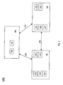
- Fig. 1 shows a first schematic block diagram illustrating a communication network 100 including various apparatus embodiments.
- the communication network 100 comprises a first monitoring component N1, a second monitoring component N2 and a management centre MC.
- First and second monitoring components N1 and N2 are incorporated in separate network nodes (not shown), and management centre MC is a separate entity within the communication network.
- Monitoring component N1 is in communication via link 150 with monitoring component N2.
- Monitoring component N1 also communicates (via link 130) with management centre MC, and management centre MC communicates via link 145 with monitoring component N2. Network traffic is forwarded between network components N1 and N2 over link 150.
- Monitoring component N1 comprises a function 115 for providing a first set of local identifiers from a larger second set of local identifiers.
- the first set of local identifiers is in this embodiment selected within and by the first monitoring component.
- the local identifiers are locally assigned and capable of providing a unique identification for a network connection within the first monitoring component N1.
- First monitoring component N1 further comprises a filtering function 116 for filtering network connections, an allocation function 117 for allocating a local identifier of the first set of local identifiers to a network connection in case a filter condition applies during the filtering, a checking function 118 for checking associations of network traffic with local identifiers, and a monitoring function 119 for monitoring network traffic, which is associated with a local identifier from the first set of local identifiers.
- a filtering function 116 for filtering network connections
- an allocation function 117 for allocating a local identifier of the first set of local identifiers to a network connection in case a filter condition applies during the filtering
- a checking function 118 for checking associations of network traffic with local identifiers
- a monitoring function 119 for monitoring network traffic, which is associated with a local identifier from the first set of local identifiers.
- Monitoring component N2 has a similar configuration like monitoring component N1 and comprises a function 125 for providing a first set of local identifiers from a larger second set of local identifiers, a filtering function 126 for filtering network connections, an allocation function 127 for allocating a local identifier of the first set of local identifiers to a network connection in case a filter condition applies during the filtering, a checking function 128 for checking associations of network traffic with local identifiers and a monitoring function 129 for monitoring network traffic, which is associated with a local identifier from the first set of local identifiers.
- Management centre MC comprises a forwarding function 130 and an interface 131.
- Forwarding function forwards via link 130 filter conditions to the first monitoring component N1 for filtering network connections during network connections setup procedures.
- Interface 131 is configured to receive the first set of local identifiers from first monitoring component N1 and, optionally, to forward it to second monitoring component N2.
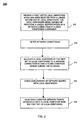
- Fig. 2 shows a flow chart illustrating a first method embodiment relating to monitoring network traffic.
- the method embodiment may be practiced by one or both of monitoring components N1 or N2 shown in Fig. 1 or by any other apparatuses.
- the method starts in step 205 with providing a first set of local identifiers selected from a lager second set of local identifiers.
- the selection may, for example, be performed by one of monitoring components N1 and N2, or, in the alternative, by management centre MC and signalled to one or both of monitoring components N1 and N2.
- the local identifiers are capable of providing a unique identification of a network connection at least at a first monitoring component.
- step 210 network connections are filtered.
- step 215 a local identifier of the first set of local identifiers is allocated to a network connection in case a filter condition applies during the filtering.
- step 220 associations of network traffic with local identifiers are checked.
- step 225 network traffic is selectively monitored if, and only if, it is associated with a local identifier from the first set of local identifiers. The monitoring may be performed with the aim of determining QoS parameters or general statistics.
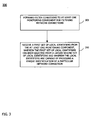
- Fig. 3 shows a flow chart 300 of a further method embodiment.
- the method embodiment shown in Fig. 3 may be practiced by management centre MC shown in Fig. 1 or by other apparatuses.
- the method starts in step 305 with forwarding filter conditions to at least one monitoring component for filtering network connections during network connection setup procedures. Thereafter, in step 310, a first set of local identifiers is received from the at least one monitoring component.
- the first set of local identifiers has been selected from a larger second set of local identifiers, and the local identifiers are capable of providing a unique identification of a particular network connection.
- UMTS Universal Mobile Telecommunications System
- GSM Global System for Mobile Communication
- Fig. 4 shows a schematic block diagram illustrating a communication network 400 including three network nodes N1, N2 and N3 for performing monitoring functions.
- the network nodes are in communication with a management centre MC.
- the communication network 400 may further comprise an external capturing device 405. Data packets sent from a user terminal (not shown) to network node N1 are forwarded within network 400 via network nodes N2 and N3 and are transferred to another user terminal (not shown).
- the user terminals may be stationary or mobile devices.
- a network connection setup procedure takes place at network node N1. More specifically, a filtering function 415 within network node N1 filters incoming network traffic during connection setup. In case a connection setup message arrives in network node N1 via its interface, a filtering function based on the filter conditions received via link 430 from management centre MC is performed at filtering function 415. In this exemplary embodiment, the filtering function is based on the filter condition if a mobile terminal (not shown) is located in a certain network cell (not shown) which is known for having a high traffic load.
- network node N1 assigns a local identifier from the first set of local identifiers to the network connection (network node N1 has initially selected a first set of local identifiers from a larger second set of local identifiers).
- the selection of the subscribers to be monitored, i.e. the filter condition, is important for receiving optimised traffic monitoring data.
- the filtering procedure will be described in more detail below with regard to Fig. 5 .
- associations of incoming network traffic with any one of the allocated local identifiers are checked within network node N1. This may for example be realized by checking incoming data packets for their associations with any one of the previously selected and assigned local identifiers. In case incoming network traffic is actually associated with the allocated local identifier, this network traffic is monitored.
- management centre MC forwards filter conditions to network nodes N1, N2, N3, requests the first set of local identifiers (and/or local identifiers from the first set that have actually been allocated) from network node N1, and forwards the first set of local identifiers (and/or the allocated local identifiers) to network nodes N2 and N3.
- Management centre MC enables coordinated traffic monitoring within the network between the network nodes by forwarding local identifiers which have been allocated for traffic monitoring by network node N1 to all relevant network nodes N2 and N3.
- Management centre MC may also provide a matching network or a look-up table (not shown) in order to provide an association between local identifiers of network node N1 and corresponding local identifiers in other network nodes N2 and N3. Since the management centre MS may provide a sharing the local identifiers allocated for traffic monitoring among all network nodes N1, of N2, and N3, real time signalling between the network nodes can be avoided.
- Fig. 4 further shows an optional physical monitoring port 425. Monitored traffic may be forwarded to physical monitoring port 425.
- Network node N1 may also comprise an optional traffic filter 420.
- An external capturing device 405 is located between network nodes N1 and N2. Management centre MC may forward the first set of local identifiers, which it has received from network node N1, to external capturing device 405. Thereafter, external capturing device 105 captures network traffic which is associated with the specific local identifier of the first set of local identifiers. Within external capturing device 405, the captured data may be stored and further processed for network analyzation purposes.
- An advantage of the approach proposed herein is that not all network traffic passing the monitoring component is monitored, but only the network traffic which is associated with a local identifier from the selected first set of local identifiers. Therefore, the captured traffic is significantly decreased as compared to known solutions.
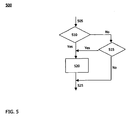
- an incoming connection setup message 505 arrives via an interface at a monitoring component, e.g. at network node N1.
- Filtering function checks 510 if a local identifier from the first set of local identifiers has already been allocated to the incoming network connection. In case a local identifier from the first set of local identifiers has been allocated to the network connection (Yes), the network connection is marked and the local identifier remains allocated 520.
- Filtering function 515 determines if a filtering condition for the incoming network connection applies.
- the filtering condition is based on whether a subscriber is located in a certain network cell which is known for high traffic load.
- connection setup is continued 525. In this case, no traffic monitoring for this network connection takes place.
- a filter condition applies (Yes), i.e. the subscriber which is initiating network connection setup is located within the specific network cell, the network connection is marked 520 in order to allocate a local identifier from the first set of local identifiers to the incoming network connection. Thereafter, connection setup continues 525. In this case, the incoming connection is selected for network traffic monitoring.
- Fig. 6 shows an exemplary embodiment of a communication network 600 in which filter signalling messages are captured at UMTS interfaces.
- the embodiment according to Fig. 6 shows parts of a UMTS network as specified in the 3GPP standard.
- the traffic monitoring task according to this embodiment is to capture all signalling messages of a subset of subscribers.
- the network shown in Fig. 6 comprises a Node B, an RNC, two SGSNs and one GGSN.
- Fig. 6 schematically illustrates the (larger) sets of local identifiers 605, 615 und 625 as tubes having a larger diameter at the different network interfaces between the network nodes. From each larger set of local identifiers 605, 615 and 625, a smaller set (or subset) of local identifiers 610, 620 and 630 is selected as visualized by a tube having a smaller diameter but located within the respective tube with larger diameter.
- the local identifiers 605, 615, 625 of the signalling bearers are regarded.
- the local identifiers of the Iub interface between NodeB and RNC are Stream Control Transmission Protocol (SCTP) ports 605.
- the local identifiers of the Iu-PS interface between RNC and SGSN are the Skinny Client Control Protocol (SCCP) Local References (LocRef) 615.
- the local identifiers of the Gn interface between SGSN and GGSN are the GPRS Tunnelling Protocol Control (GTP-C) Tunnel Endpoint Identifier (TEID) 625.
- GTP-C GPRS Tunnelling Protocol Control
- the network for example the RNC, is able to decide whether the selected local identifiers are to be allocated from the sets of local identifiers 610, 620 and 630. All network nodes participating in the communication are able to allocate the respective local identifiers.
- the captured data packets may then be transmitted from the monitoring components to a central physical monitoring port (not shown), in which the traffic data from all monitoring components may be processed and further analyzed if necessary.
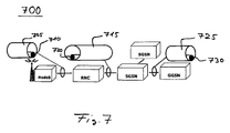
- Fig. 7 shows an exemplary embodiment of a UMTS network 700 in which filtered user plane traffic is captured at the interfaces between the network nodes.
- Fig. 7 shows a UMTS network comprising a NodeB, a RNC, two SGSNs and one GGSN.
- the traffic monitoring task shown in Fig. 7 is to capture all user plane data packets of a subset of subscribers at the interfaces between the network nodes.
- Fig. 7 shows the larger sets local identifiers 705, 715, 725 of the transport bearers.
- the local identifiers of the Iub interface between NodeB and RNC are User Data Protocol (UDP) ports 705 which are communicated as a NodeB Adaption Protocol (NBAP) Binding-ID.
- UDP User Data Protocol
- NBAP NodeB Adaption Protocol
- the local identifiers of the Iu-PS interface between RNC and SGSN are the GPRS Tunnelling-User (GTP-U) TEID 715 which are established by the Radio Access Network Application Part (RANAP) and the transport Binding-ID.
- the local identifiers of the Gn interface between SGSN and GGSN are the GTP-U TEID 725. From the larger sets of local identifiers 705, 715 and 725 (again visualized as tubes having a larger diameter), individual smaller sets of local identifiers 710, 720 and 730 (again visualized as tubes of smaller diameter arranged within larger diameter tubes) are selected.
- the network for example the RNC, is able to decide whether one of the selected local identifiers is to be allocated for indicating that the respective network connection shall be monitored. All network nodes participating in the communication are able to allocate the respective local identifiers from the selected sets of local identifiers 710, 720 and 730.
- P-TMSI Packet Temporary Mobile Subscriber Identity
- the technique for monitoring traffic in a network proposed herein has a plurality of advantages.
- By means of the proposed smart coordination and selection of local identifiers for monitoring purposes events of subscribers taking place at several monitoring components can be recorded and correlated. This significantly increases the observability of network traffic for performance and fault management purposes.
- Another advantage is that the set of subscribers to be monitored can be individually controlled.
- the technique for monitoring traffic in a network as proposed herein requires some more intelligence at the monitoring component; however, it does not necessarily impose additional processing load on the network node or the monitoring component.
- Any network node may act as a monitoring component, and filtering and monitoring functions can be completely separated from the core network functions.
- the monitoring functions and the core network functions can be executed by separate cards or blades within the network node.
- Selection of subscribers for traffic monitoring may be performed by the network (via filter rules). Therefore, the requirements on the monitoring components are rather low. For example, protocol parsing and global ID matching is not necessary.
- Such functions are executed by the network independent of traffic monitoring. The functions may be reused in order assist traffic monitoring. Since the filtering task is reduced to checking local identifiers for matches at the lowest protocol layer, the monitoring component can have a simple structure and can process network traffic, e.g. data packets, with a high transmission rate.
- the network traffic monitoring may be implemented within the network, i.e. within the network nodes. Therefore, external probes and management systems can be avoided. This may decrease the cost for traffic monitoring.
- the sets of local identifier are selected in a coordinated way, because events relating to a subscriber which occur at different monitoring components can be correlated during post-processing.
- Post-processing can for example be a calculation of key performance indicators or a fault localisation.
Landscapes
- Engineering & Computer Science (AREA)
- Computer Networks & Wireless Communication (AREA)
- Signal Processing (AREA)
- Data Exchanges In Wide-Area Networks (AREA)
- Mobile Radio Communication Systems (AREA)
Claims (13)
- Procédé (200) de surveillance de trafic dans un réseau comprenant un premier composant de surveillance (N1), un deuxième composant de surveillance (N2), et un centre de gestion (MC), le procédé comprenant les étapes suivantes de :prévision (205) au niveau du premier composant de surveillance (N1) d'un premier ensemble d'identifiants locaux qui a été choisi parmi un deuxième ensemble plus grand d'identifiants locaux, les identifiants locaux étant utilisés localement au sein d'un noeud de réseau et étant aptes à délivrer une identification unique d'une connexion réseau au niveau du premier composant de surveillance (N1) ;contrôle au niveau du premier composant de surveillance (N1) que des identifiants locaux du premier ensemble d'identifiants locaux ont été attribués à des connexions réseau entrantes ;filtrage (210) au niveau du premier composant de surveillance (N1) d'un message d'établissement de connexion réseau entrante sur la base d'un état de filtre dans le cas où aucun identifiant local du premier ensemble d'identifiants locaux n'a été attribué à la connexion réseau entrante ;attribution (215) au niveau du premier composant de surveillance (N1) d'un identifiant local du premier ensemble d'identifiants locaux à la connexion réseau dans le cas où l'état de filtre s'applique pendant le filtrage ;demande des identifiants locaux attribués au premier composant de surveillance (N1) par le centre de gestion (MC) ;envoi des identifiants locaux attribués au deuxième composant de surveillance (N2) par le centre de gestion (MC) ; etcontrôle (220) au niveau du premier (N1) et du deuxième (N2) composants de surveillance de paquets de données entrants en termes d'associations avec les identifiants locaux attribués,caractérisé parla surveillance (225) sélective au niveau du premier (N1) et du deuxième (N2) composants de surveillance d'un trafic réseau associé avec un identifiant local du premier ensemble d'identifiants locaux, dans lequelle filtrage basé sur l'état de filtre n'est effectué qu'au niveau du premier composant de surveillance (N1).
- Procédé selon la revendication 1, dans lequel
des connexions réseau sont filtrées pendant les procédures d'établissement de connexion réseau. - Procédé selon l'une des revendications 1 ou 2,
dans lequel l'état de filtre est basé sur au moins l'un d'un filtrage aléatoire, d'une sélection d'Identités Internationales d'Abonnés Mobiles (IMSI) prédéfinies et d'un filtrage dépendant de la localisation d'abonnés. - Procédé selon l'une des revendications 1 à 3,
dans lequel seuls des identifiants locaux de la couche de protocole applicable la plus basse du réseau sont surveillés. - Procédé selon l'une des revendications 1 à 4,
dans lequel l'état de filtre est reçu par le premier composant de surveillance (N1) d'un centre de gestion (MC). - Procédé selon l'une quelconque des revendications précédentes, comprenant en outre l'étape de
envoi du premier ensemble d'identifiants locaux du premier composant de surveillance (N1) au deuxième composant de surveillance (N2). - Procédé selon l'une quelconque des revendications précédentes, comprenant en outre l'étape de
envoi du premier ensemble d'identifiants locaux du premier composant de surveillance (N1) à un centre de gestion (MC). - Procédé selon l'une quelconque des revendications précédentes, comprenant en outre l'étape de
journalisation d'événements incluant des horodatages associés avec le trafic réseau surveillé. - Procédé selon la revendication 8, comprenant en outre l'étape de
envoi des événements journalisés à un port physique de surveillance. - Procédé selon l'une quelconque des revendications précédentes,
dans lequel le premier ensemble d'identifiants locaux est une plage continue d'identifiants locaux. - Produit de programme informatique incluant des parties de code de programme pour mettre en oeuvre toutes les étapes de procédé selon l'une des revendications 1 à 10 lorsque le produit de programme informatique est exécuté sur un ou plusieurs composants d'un réseau.
- Produit de programme informatique selon la revendication 11, stocké sur un support d'enregistrement lisible par un ordinateur.
- Système de réseau (100) pour surveiller un trafic, comprenant un premier composant de surveillance (N1), un deuxième composant de surveillance (N2) et un centre de gestion (MC),
le premier composant de surveillance (N1) étant adapté àprévoir un premier ensemble d'identifiants locaux qui a été choisi parmi un deuxième ensemble plus grand d'identifiants locaux, les identifiants locaux étant utilisés localement au sein d'un noeud de réseau et étant aptes à délivrer une identification unique d'une connexion réseau au niveau du premier composant de surveillance (N1) ;contrôler que des identifiants locaux du premier ensemble d'identifiants locaux ont été attribués à des connexions réseau entrantes ;filtrer un message d'établissement de connexion réseau entrante sur la base d'un état de filtre dans le cas où aucun identifiant local du premier ensemble d'identifiants locaux n'a été attribué à la connexion réseau entrante ;attribuer un identifiant local du premier ensemble d'identifiants locaux à la connexion réseau dans le cas où l'état de filtre s'applique pendant le filtrage ; etcontrôler des paquets de données en termes d'associations avec les identifiants locaux attribués ;le centre de gestion (MC) étant adapté àdemander les identifiants locaux attribués au premier composant de surveillance (N1), etenvoyer les identifiants locaux attribués au deuxième composant de surveillance (N2) ; etle deuxième composant de surveillance (N2) étant adapté àcontrôler des paquets de données en termes d'associations avec les identifiants locaux attribués ;caractérisé en ce que
le premier composant de surveillance (N1) étant adapté à surveiller sélectivement un trafic réseau associé avec un identifiant local du premier ensemble d'identifiants locaux, et
le deuxième composant de surveillance (N2) étant adapté à surveiller sélectivement un trafic réseau associé avec un identifiant local du premier ensemble d'identifiants locaux, dans lequel
le filtrage basé sur l'état de filtre n'est effectué qu'au niveau du premier composant de surveillance (N1).
Applications Claiming Priority (1)
| Application Number | Priority Date | Filing Date | Title |
|---|---|---|---|
| PCT/EP2007/008962 WO2009049644A1 (fr) | 2007-10-16 | 2007-10-16 | Procédé et composant de surveillance pour la surveillance de trafic de réseau |
Publications (2)
| Publication Number | Publication Date |
|---|---|
| EP2210370A1 EP2210370A1 (fr) | 2010-07-28 |
| EP2210370B1 true EP2210370B1 (fr) | 2011-12-07 |
Family
ID=39846636
Family Applications (1)
| Application Number | Title | Priority Date | Filing Date |
|---|---|---|---|
| EP07819032A Not-in-force EP2210370B1 (fr) | 2007-10-16 | 2007-10-16 | Procédé et composant de surveillance pour la surveillance de trafic de réseau |
Country Status (5)
| Country | Link |
|---|---|
| US (1) | US8750133B2 (fr) |
| EP (1) | EP2210370B1 (fr) |
| CN (1) | CN101843134B (fr) |
| AT (1) | ATE536678T1 (fr) |
| WO (1) | WO2009049644A1 (fr) |
Families Citing this family (16)
| Publication number | Priority date | Publication date | Assignee | Title |
|---|---|---|---|---|
| GB2472231B (en) * | 2009-07-29 | 2012-03-07 | Roke Manor Research | Networked probe system |
| US8214105B2 (en) * | 2009-08-21 | 2012-07-03 | Metra Electronics Corporation | Methods and systems for automatic detection of steering wheel control signals |
| US8285446B2 (en) | 2009-08-21 | 2012-10-09 | Circuit Works, Inc. | Methods and systems for providing accessory steering wheel controls |
| US8014920B2 (en) * | 2009-08-21 | 2011-09-06 | Metra Electronics Corporation | Methods and systems for providing accessory steering wheel controls |
| US9338075B2 (en) * | 2009-10-09 | 2016-05-10 | Nec Europe Ltd. | Method for monitoring traffic in a network and a network |
| US20110141924A1 (en) * | 2009-12-16 | 2011-06-16 | Tektronix Inc. | System and Method for Filtering High Priority Signaling and Data for Fixed and Mobile Networks |
| US20130081072A1 (en) * | 2011-09-28 | 2013-03-28 | Cello Partnership | Preemptive video delivery to devices in a wireless network |
| US20130272136A1 (en) * | 2012-04-17 | 2013-10-17 | Tektronix, Inc. | Session-Aware GTPv1 Load Balancing |
| US9619114B2 (en) | 2012-06-11 | 2017-04-11 | Automotive Data Solutions, Inc. | Method and system to configure an aftermarket interface module using a graphical user interface |
| US9602383B2 (en) * | 2012-10-11 | 2017-03-21 | Telefonaktiebolaget Lm Ericsson (Publ) | General packet radio service tunnel performance monitoring |
| US9338678B2 (en) | 2012-10-11 | 2016-05-10 | Telefonaktiebolaget Lm Ericsson (Publ) | Performance monitoring of control and provisioning of wireless access points (CAPWAP) control channels |
| CN103618733B (zh) * | 2013-12-06 | 2017-06-27 | 北京中创腾锐技术有限公司 | 一种应用于移动互联网的数据过滤系统及方法 |
| US9667521B2 (en) | 2014-01-27 | 2017-05-30 | Vencore Labs, Inc. | System and method for network traffic profiling and visualization |
| CN104955097B (zh) * | 2015-06-23 | 2018-04-27 | 珠海世纪鼎利科技股份有限公司 | 基于核密度分布的移动网络信令监测方法 |
| CN111147323A (zh) * | 2019-12-17 | 2020-05-12 | 中国联合网络通信集团有限公司 | 测速方法及装置 |
| WO2023079354A1 (fr) * | 2021-11-08 | 2023-05-11 | Telefonaktiebolaget Lm Ericsson (Publ) | Génération d'analytique dans un réseau de communication |
Family Cites Families (15)
| Publication number | Priority date | Publication date | Assignee | Title |
|---|---|---|---|---|
| KR0136519B1 (ko) * | 1994-07-14 | 1998-06-01 | 양승택 | 연결설정방식의 비연결형 데이타 처리장치 및 그 방법 |
| DE69728079T2 (de) * | 1996-05-03 | 2005-01-20 | Agilent Technologies, Inc. (n.d.Ges.d.Staates Delaware), Palo Alto | Verfahren und Einrichtung zum Verfolgen der Änderung des Identifizierungskodes in einem mobilen Kommunikationssystem |
| JP3507270B2 (ja) * | 1997-02-20 | 2004-03-15 | 株式会社日立製作所 | ネットワーク管理システム、ネットワーク機器、ネットワーク管理方法およびネットワーク管理ツール |
| JP3994614B2 (ja) * | 2000-03-13 | 2007-10-24 | 株式会社日立製作所 | パケット交換機、ネットワーク監視システム及びネットワーク監視方法 |
| FI20002848A (fi) * | 2000-12-22 | 2002-06-23 | Nokia Corp | Vuon valvonta tietoliikenneverkossa |
| US20020176378A1 (en) * | 2001-05-22 | 2002-11-28 | Hamilton Thomas E. | Platform and method for providing wireless data services |
| KR100428767B1 (ko) * | 2002-01-11 | 2004-04-28 | 삼성전자주식회사 | 트래픽 정보를 이용한 가입자 라우팅 설정 방법 및 이를위한 기록매체 |
| US7286482B2 (en) * | 2002-11-29 | 2007-10-23 | Alcatel Lucent | Decentralized SLS monitoring in a differentiated service environment |
| US20050071457A1 (en) * | 2003-08-27 | 2005-03-31 | Siew-Hong Yang-Huffman | System and method of network fault monitoring |
| FR2869489B1 (fr) * | 2004-04-27 | 2006-07-28 | Alcatel Sa | Correlation de mesures passives de type bout-en-bout, au moyen de filtres hierarchises |
| JP4415789B2 (ja) * | 2004-08-20 | 2010-02-17 | 株式会社日立製作所 | 無線通信システム |
| WO2006057586A1 (fr) * | 2004-11-26 | 2006-06-01 | Telefonaktiebolaget Lm Ericsson (Publ) | Analyse de performance d'un reseau de telecommunications mobile a commutation de circuits |
| US8270309B1 (en) * | 2005-03-07 | 2012-09-18 | Verizon Services Corp. | Systems for monitoring delivery performance of a packet flow between reference nodes |
| US20060224822A1 (en) * | 2005-03-18 | 2006-10-05 | Blomquist Scott A | System and method for tagging and filtering electronic data |
| KR100784729B1 (ko) | 2006-08-01 | 2007-12-12 | 주식회사 이노와이어리스 | Wcdma 네트워크에서 이동전화번호를 이용한 데이터수집방법 |
-
2007
- 2007-10-16 US US12/738,400 patent/US8750133B2/en not_active Expired - Fee Related
- 2007-10-16 WO PCT/EP2007/008962 patent/WO2009049644A1/fr active Application Filing
- 2007-10-16 EP EP07819032A patent/EP2210370B1/fr not_active Not-in-force
- 2007-10-16 AT AT07819032T patent/ATE536678T1/de active
- 2007-10-16 CN CN200780101131.7A patent/CN101843134B/zh not_active Expired - Fee Related
Also Published As
| Publication number | Publication date |
|---|---|
| US20100226278A1 (en) | 2010-09-09 |
| US8750133B2 (en) | 2014-06-10 |
| ATE536678T1 (de) | 2011-12-15 |
| WO2009049644A1 (fr) | 2009-04-23 |
| EP2210370A1 (fr) | 2010-07-28 |
| CN101843134A (zh) | 2010-09-22 |
| CN101843134B (zh) | 2014-05-07 |
Similar Documents
| Publication | Publication Date | Title |
|---|---|---|
| EP2210370B1 (fr) | Procédé et composant de surveillance pour la surveillance de trafic de réseau | |
| US11463918B2 (en) | Data processing method and apparatus, and data sending method and apparatus | |
| JP7147063B2 (ja) | ユーザアクセス制御方法、情報送信方法および装置 | |
| US7929512B2 (en) | Performance management of cellular mobile packet data networks | |
| EP2744151B1 (fr) | Procédé, système et support lisible par ordinateur pour la surveillance du trafic parmi des agents de coeur de DIAMETER | |
| EP2676470B1 (fr) | Mesures centrées sur un service pour minimiser les essais de couverture radio | |
| EP3235177B1 (fr) | Coordination de mesurages dans des communications | |
| KR101503680B1 (ko) | 네트워크 분석을 위한 방법 및 장치 | |
| US9439087B2 (en) | Analyzing radio network coverage | |
| US9407522B2 (en) | Initiating data collection based on WiFi network connectivity metrics | |
| US9185001B2 (en) | Backhaul network performance monitoring using segmented analytics | |
| US10756987B2 (en) | Technique for handling service level related performance data for roaming user terminals | |
| JP2012156988A (ja) | ネットワークのトポロジを識別する方法、ネットワーク・モニタリング・システム及びコンピュータ読出し可能な蓄積媒体 | |
| JP2005006312A (ja) | モバイルデータ通信のサービス使用状況レコードを生成する装置および方法 | |
| EP2996283B1 (fr) | Systèmes et dispositifs permettant de déterminer des indicateurs clés de performance au moyen de statistiques inférentielles | |
| US7630335B2 (en) | Location signaling for large-scale, end-to-end, quality-of-service monitoring of mobile telecommunication networks | |
| US7453817B1 (en) | Central traffic correlation system | |
| CN116472702A (zh) | 数据处理节点装置及在该装置中执行的信息传输方法 | |
| US20070014311A1 (en) | Method and apparatus for grouping messages across a point to multipoint network | |
| US9667445B2 (en) | Signaling plane delay KPI monitoring in live network | |
| WO2024224142A1 (fr) | Rapport de transport par radio pour une analyse |
Legal Events
| Date | Code | Title | Description |
|---|---|---|---|
| PUAI | Public reference made under article 153(3) epc to a published international application that has entered the european phase |
Free format text: ORIGINAL CODE: 0009012 |
|
| 17P | Request for examination filed |
Effective date: 20100407 |
|
| AK | Designated contracting states |
Kind code of ref document: A1 Designated state(s): AT BE BG CH CY CZ DE DK EE ES FI FR GB GR HU IE IS IT LI LT LU LV MC MT NL PL PT RO SE SI SK TR |
|
| AX | Request for extension of the european patent |
Extension state: AL BA HR MK RS |
|
| DAX | Request for extension of the european patent (deleted) | ||
| 17Q | First examination report despatched |
Effective date: 20110114 |
|
| GRAP | Despatch of communication of intention to grant a patent |
Free format text: ORIGINAL CODE: EPIDOSNIGR1 |
|
| GRAS | Grant fee paid |
Free format text: ORIGINAL CODE: EPIDOSNIGR3 |
|
| GRAA | (expected) grant |
Free format text: ORIGINAL CODE: 0009210 |
|
| AK | Designated contracting states |
Kind code of ref document: B1 Designated state(s): AT BE BG CH CY CZ DE DK EE ES FI FR GB GR HU IE IS IT LI LT LU LV MC MT NL PL PT RO SE SI SK TR |
|
| REG | Reference to a national code |
Ref country code: GB Ref legal event code: FG4D |
|
| REG | Reference to a national code |
Ref country code: CH Ref legal event code: EP |
|
| REG | Reference to a national code |
Ref country code: IE Ref legal event code: FG4D |
|
| REG | Reference to a national code |
Ref country code: DE Ref legal event code: R096 Ref document number: 602007019229 Country of ref document: DE Effective date: 20120223 |
|
| REG | Reference to a national code |
Ref country code: NL Ref legal event code: VDEP Effective date: 20111207 |
|
| PG25 | Lapsed in a contracting state [announced via postgrant information from national office to epo] |
Ref country code: LT Free format text: LAPSE BECAUSE OF FAILURE TO SUBMIT A TRANSLATION OF THE DESCRIPTION OR TO PAY THE FEE WITHIN THE PRESCRIBED TIME-LIMIT Effective date: 20111207 |
|
| LTIE | Lt: invalidation of european patent or patent extension |
Effective date: 20111207 |
|
| PG25 | Lapsed in a contracting state [announced via postgrant information from national office to epo] |
Ref country code: SE Free format text: LAPSE BECAUSE OF FAILURE TO SUBMIT A TRANSLATION OF THE DESCRIPTION OR TO PAY THE FEE WITHIN THE PRESCRIBED TIME-LIMIT Effective date: 20111207 Ref country code: SI Free format text: LAPSE BECAUSE OF FAILURE TO SUBMIT A TRANSLATION OF THE DESCRIPTION OR TO PAY THE FEE WITHIN THE PRESCRIBED TIME-LIMIT Effective date: 20111207 Ref country code: LV Free format text: LAPSE BECAUSE OF FAILURE TO SUBMIT A TRANSLATION OF THE DESCRIPTION OR TO PAY THE FEE WITHIN THE PRESCRIBED TIME-LIMIT Effective date: 20111207 Ref country code: NL Free format text: LAPSE BECAUSE OF FAILURE TO SUBMIT A TRANSLATION OF THE DESCRIPTION OR TO PAY THE FEE WITHIN THE PRESCRIBED TIME-LIMIT Effective date: 20111207 Ref country code: GR Free format text: LAPSE BECAUSE OF FAILURE TO SUBMIT A TRANSLATION OF THE DESCRIPTION OR TO PAY THE FEE WITHIN THE PRESCRIBED TIME-LIMIT Effective date: 20120308 |
|
| PG25 | Lapsed in a contracting state [announced via postgrant information from national office to epo] |
Ref country code: CY Free format text: LAPSE BECAUSE OF FAILURE TO SUBMIT A TRANSLATION OF THE DESCRIPTION OR TO PAY THE FEE WITHIN THE PRESCRIBED TIME-LIMIT Effective date: 20111207 Ref country code: BE Free format text: LAPSE BECAUSE OF FAILURE TO SUBMIT A TRANSLATION OF THE DESCRIPTION OR TO PAY THE FEE WITHIN THE PRESCRIBED TIME-LIMIT Effective date: 20111207 |
|
| PG25 | Lapsed in a contracting state [announced via postgrant information from national office to epo] |
Ref country code: CZ Free format text: LAPSE BECAUSE OF FAILURE TO SUBMIT A TRANSLATION OF THE DESCRIPTION OR TO PAY THE FEE WITHIN THE PRESCRIBED TIME-LIMIT Effective date: 20111207 Ref country code: EE Free format text: LAPSE BECAUSE OF FAILURE TO SUBMIT A TRANSLATION OF THE DESCRIPTION OR TO PAY THE FEE WITHIN THE PRESCRIBED TIME-LIMIT Effective date: 20111207 Ref country code: IS Free format text: LAPSE BECAUSE OF FAILURE TO SUBMIT A TRANSLATION OF THE DESCRIPTION OR TO PAY THE FEE WITHIN THE PRESCRIBED TIME-LIMIT Effective date: 20120407 Ref country code: BG Free format text: LAPSE BECAUSE OF FAILURE TO SUBMIT A TRANSLATION OF THE DESCRIPTION OR TO PAY THE FEE WITHIN THE PRESCRIBED TIME-LIMIT Effective date: 20120307 Ref country code: SK Free format text: LAPSE BECAUSE OF FAILURE TO SUBMIT A TRANSLATION OF THE DESCRIPTION OR TO PAY THE FEE WITHIN THE PRESCRIBED TIME-LIMIT Effective date: 20111207 |
|
| PG25 | Lapsed in a contracting state [announced via postgrant information from national office to epo] |
Ref country code: PT Free format text: LAPSE BECAUSE OF FAILURE TO SUBMIT A TRANSLATION OF THE DESCRIPTION OR TO PAY THE FEE WITHIN THE PRESCRIBED TIME-LIMIT Effective date: 20120409 Ref country code: RO Free format text: LAPSE BECAUSE OF FAILURE TO SUBMIT A TRANSLATION OF THE DESCRIPTION OR TO PAY THE FEE WITHIN THE PRESCRIBED TIME-LIMIT Effective date: 20111207 Ref country code: PL Free format text: LAPSE BECAUSE OF FAILURE TO SUBMIT A TRANSLATION OF THE DESCRIPTION OR TO PAY THE FEE WITHIN THE PRESCRIBED TIME-LIMIT Effective date: 20111207 |
|
| REG | Reference to a national code |
Ref country code: AT Ref legal event code: MK05 Ref document number: 536678 Country of ref document: AT Kind code of ref document: T Effective date: 20111207 |
|
| PLBE | No opposition filed within time limit |
Free format text: ORIGINAL CODE: 0009261 |
|
| STAA | Information on the status of an ep patent application or granted ep patent |
Free format text: STATUS: NO OPPOSITION FILED WITHIN TIME LIMIT |
|
| PG25 | Lapsed in a contracting state [announced via postgrant information from national office to epo] |
Ref country code: DK Free format text: LAPSE BECAUSE OF FAILURE TO SUBMIT A TRANSLATION OF THE DESCRIPTION OR TO PAY THE FEE WITHIN THE PRESCRIBED TIME-LIMIT Effective date: 20111207 |
|
| 26N | No opposition filed |
Effective date: 20120910 |
|
| REG | Reference to a national code |
Ref country code: DE Ref legal event code: R097 Ref document number: 602007019229 Country of ref document: DE Effective date: 20120910 |
|
| PG25 | Lapsed in a contracting state [announced via postgrant information from national office to epo] |
Ref country code: AT Free format text: LAPSE BECAUSE OF FAILURE TO SUBMIT A TRANSLATION OF THE DESCRIPTION OR TO PAY THE FEE WITHIN THE PRESCRIBED TIME-LIMIT Effective date: 20111207 |
|
| PG25 | Lapsed in a contracting state [announced via postgrant information from national office to epo] |
Ref country code: ES Free format text: LAPSE BECAUSE OF FAILURE TO SUBMIT A TRANSLATION OF THE DESCRIPTION OR TO PAY THE FEE WITHIN THE PRESCRIBED TIME-LIMIT Effective date: 20120318 |
|
| PG25 | Lapsed in a contracting state [announced via postgrant information from national office to epo] |
Ref country code: MC Free format text: LAPSE BECAUSE OF NON-PAYMENT OF DUE FEES Effective date: 20121031 |
|
| REG | Reference to a national code |
Ref country code: CH Ref legal event code: PL |
|
| PG25 | Lapsed in a contracting state [announced via postgrant information from national office to epo] |
Ref country code: FI Free format text: LAPSE BECAUSE OF FAILURE TO SUBMIT A TRANSLATION OF THE DESCRIPTION OR TO PAY THE FEE WITHIN THE PRESCRIBED TIME-LIMIT Effective date: 20111207 |
|
| REG | Reference to a national code |
Ref country code: IE Ref legal event code: MM4A |
|
| REG | Reference to a national code |
Ref country code: FR Ref legal event code: ST Effective date: 20130628 |
|
| PG25 | Lapsed in a contracting state [announced via postgrant information from national office to epo] |
Ref country code: CH Free format text: LAPSE BECAUSE OF NON-PAYMENT OF DUE FEES Effective date: 20121031 Ref country code: LI Free format text: LAPSE BECAUSE OF NON-PAYMENT OF DUE FEES Effective date: 20121031 Ref country code: IE Free format text: LAPSE BECAUSE OF NON-PAYMENT OF DUE FEES Effective date: 20121016 |
|
| PG25 | Lapsed in a contracting state [announced via postgrant information from national office to epo] |
Ref country code: FR Free format text: LAPSE BECAUSE OF NON-PAYMENT OF DUE FEES Effective date: 20121031 |
|
| PG25 | Lapsed in a contracting state [announced via postgrant information from national office to epo] |
Ref country code: MT Free format text: LAPSE BECAUSE OF FAILURE TO SUBMIT A TRANSLATION OF THE DESCRIPTION OR TO PAY THE FEE WITHIN THE PRESCRIBED TIME-LIMIT Effective date: 20111207 |
|
| PG25 | Lapsed in a contracting state [announced via postgrant information from national office to epo] |
Ref country code: TR Free format text: LAPSE BECAUSE OF FAILURE TO SUBMIT A TRANSLATION OF THE DESCRIPTION OR TO PAY THE FEE WITHIN THE PRESCRIBED TIME-LIMIT Effective date: 20111207 |
|
| PG25 | Lapsed in a contracting state [announced via postgrant information from national office to epo] |
Ref country code: LU Free format text: LAPSE BECAUSE OF NON-PAYMENT OF DUE FEES Effective date: 20121016 |
|
| PG25 | Lapsed in a contracting state [announced via postgrant information from national office to epo] |
Ref country code: HU Free format text: LAPSE BECAUSE OF FAILURE TO SUBMIT A TRANSLATION OF THE DESCRIPTION OR TO PAY THE FEE WITHIN THE PRESCRIBED TIME-LIMIT Effective date: 20071016 |
|
| PGFP | Annual fee paid to national office [announced via postgrant information from national office to epo] |
Ref country code: DE Payment date: 20171027 Year of fee payment: 11 |
|
| PGFP | Annual fee paid to national office [announced via postgrant information from national office to epo] |
Ref country code: GB Payment date: 20171027 Year of fee payment: 11 Ref country code: IT Payment date: 20171024 Year of fee payment: 11 |
|
| REG | Reference to a national code |
Ref country code: DE Ref legal event code: R119 Ref document number: 602007019229 Country of ref document: DE |
|
| GBPC | Gb: european patent ceased through non-payment of renewal fee |
Effective date: 20181016 |
|
| PG25 | Lapsed in a contracting state [announced via postgrant information from national office to epo] |
Ref country code: DE Free format text: LAPSE BECAUSE OF NON-PAYMENT OF DUE FEES Effective date: 20190501 |
|
| PG25 | Lapsed in a contracting state [announced via postgrant information from national office to epo] |
Ref country code: IT Free format text: LAPSE BECAUSE OF NON-PAYMENT OF DUE FEES Effective date: 20181016 Ref country code: GB Free format text: LAPSE BECAUSE OF NON-PAYMENT OF DUE FEES Effective date: 20181016 |