EP2209561B1 - Dispenser device for bi-component substances - Google Patents
Dispenser device for bi-component substances Download PDFInfo
- Publication number
- EP2209561B1 EP2209561B1 EP07866759A EP07866759A EP2209561B1 EP 2209561 B1 EP2209561 B1 EP 2209561B1 EP 07866759 A EP07866759 A EP 07866759A EP 07866759 A EP07866759 A EP 07866759A EP 2209561 B1 EP2209561 B1 EP 2209561B1
- Authority
- EP
- European Patent Office
- Prior art keywords
- dispenser device
- dispenser
- side wall
- supporting structure
- cartridges
- Prior art date
- Legal status (The legal status is an assumption and is not a legal conclusion. Google has not performed a legal analysis and makes no representation as to the accuracy of the status listed.)
- Active
Links
Images



Classifications
-
- A—HUMAN NECESSITIES
- A61—MEDICAL OR VETERINARY SCIENCE; HYGIENE
- A61C—DENTISTRY; APPARATUS OR METHODS FOR ORAL OR DENTAL HYGIENE
- A61C9/00—Impression cups, i.e. impression trays; Impression methods
- A61C9/0026—Syringes or guns for injecting impression material; Mixing impression material for immediate use
-
- A—HUMAN NECESSITIES
- A61—MEDICAL OR VETERINARY SCIENCE; HYGIENE
- A61C—DENTISTRY; APPARATUS OR METHODS FOR ORAL OR DENTAL HYGIENE
- A61C5/00—Filling or capping teeth
- A61C5/60—Devices specially adapted for pressing or mixing capping or filling materials, e.g. amalgam presses
- A61C5/62—Applicators, e.g. syringes or guns
- A61C5/64—Applicators, e.g. syringes or guns for multi-component compositions
-
- B—PERFORMING OPERATIONS; TRANSPORTING
- B05—SPRAYING OR ATOMISING IN GENERAL; APPLYING FLUENT MATERIALS TO SURFACES, IN GENERAL
- B05C—APPARATUS FOR APPLYING FLUENT MATERIALS TO SURFACES, IN GENERAL
- B05C17/00—Hand tools or apparatus using hand held tools, for applying liquids or other fluent materials to, for spreading applied liquids or other fluent materials on, or for partially removing applied liquids or other fluent materials from, surfaces
- B05C17/005—Hand tools or apparatus using hand held tools, for applying liquids or other fluent materials to, for spreading applied liquids or other fluent materials on, or for partially removing applied liquids or other fluent materials from, surfaces for discharging material from a reservoir or container located in or on the hand tool through an outlet orifice by pressure without using surface contacting members like pads or brushes
- B05C17/00553—Hand tools or apparatus using hand held tools, for applying liquids or other fluent materials to, for spreading applied liquids or other fluent materials on, or for partially removing applied liquids or other fluent materials from, surfaces for discharging material from a reservoir or container located in or on the hand tool through an outlet orifice by pressure without using surface contacting members like pads or brushes with means allowing the stock of material to consist of at least two different components
- B05C17/00566—Hand tools or apparatus using hand held tools, for applying liquids or other fluent materials to, for spreading applied liquids or other fluent materials on, or for partially removing applied liquids or other fluent materials from, surfaces for discharging material from a reservoir or container located in or on the hand tool through an outlet orifice by pressure without using surface contacting members like pads or brushes with means allowing the stock of material to consist of at least two different components with a dynamic mixer in the nozzle
-
- B—PERFORMING OPERATIONS; TRANSPORTING
- B05—SPRAYING OR ATOMISING IN GENERAL; APPLYING FLUENT MATERIALS TO SURFACES, IN GENERAL
- B05C—APPARATUS FOR APPLYING FLUENT MATERIALS TO SURFACES, IN GENERAL
- B05C17/00—Hand tools or apparatus using hand held tools, for applying liquids or other fluent materials to, for spreading applied liquids or other fluent materials on, or for partially removing applied liquids or other fluent materials from, surfaces
- B05C17/005—Hand tools or apparatus using hand held tools, for applying liquids or other fluent materials to, for spreading applied liquids or other fluent materials on, or for partially removing applied liquids or other fluent materials from, surfaces for discharging material from a reservoir or container located in or on the hand tool through an outlet orifice by pressure without using surface contacting members like pads or brushes
- B05C17/00553—Hand tools or apparatus using hand held tools, for applying liquids or other fluent materials to, for spreading applied liquids or other fluent materials on, or for partially removing applied liquids or other fluent materials from, surfaces for discharging material from a reservoir or container located in or on the hand tool through an outlet orifice by pressure without using surface contacting members like pads or brushes with means allowing the stock of material to consist of at least two different components
-
- B—PERFORMING OPERATIONS; TRANSPORTING
- B05—SPRAYING OR ATOMISING IN GENERAL; APPLYING FLUENT MATERIALS TO SURFACES, IN GENERAL
- B05C—APPARATUS FOR APPLYING FLUENT MATERIALS TO SURFACES, IN GENERAL
- B05C17/00—Hand tools or apparatus using hand held tools, for applying liquids or other fluent materials to, for spreading applied liquids or other fluent materials on, or for partially removing applied liquids or other fluent materials from, surfaces
- B05C17/005—Hand tools or apparatus using hand held tools, for applying liquids or other fluent materials to, for spreading applied liquids or other fluent materials on, or for partially removing applied liquids or other fluent materials from, surfaces for discharging material from a reservoir or container located in or on the hand tool through an outlet orifice by pressure without using surface contacting members like pads or brushes
- B05C17/01—Hand tools or apparatus using hand held tools, for applying liquids or other fluent materials to, for spreading applied liquids or other fluent materials on, or for partially removing applied liquids or other fluent materials from, surfaces for discharging material from a reservoir or container located in or on the hand tool through an outlet orifice by pressure without using surface contacting members like pads or brushes with manually mechanically or electrically actuated piston or the like
- B05C17/0103—Hand tools or apparatus using hand held tools, for applying liquids or other fluent materials to, for spreading applied liquids or other fluent materials on, or for partially removing applied liquids or other fluent materials from, surfaces for discharging material from a reservoir or container located in or on the hand tool through an outlet orifice by pressure without using surface contacting members like pads or brushes with manually mechanically or electrically actuated piston or the like with electrically actuated piston or the like
-
- B—PERFORMING OPERATIONS; TRANSPORTING
- B05—SPRAYING OR ATOMISING IN GENERAL; APPLYING FLUENT MATERIALS TO SURFACES, IN GENERAL
- B05C—APPARATUS FOR APPLYING FLUENT MATERIALS TO SURFACES, IN GENERAL
- B05C17/00—Hand tools or apparatus using hand held tools, for applying liquids or other fluent materials to, for spreading applied liquids or other fluent materials on, or for partially removing applied liquids or other fluent materials from, surfaces
- B05C17/005—Hand tools or apparatus using hand held tools, for applying liquids or other fluent materials to, for spreading applied liquids or other fluent materials on, or for partially removing applied liquids or other fluent materials from, surfaces for discharging material from a reservoir or container located in or on the hand tool through an outlet orifice by pressure without using surface contacting members like pads or brushes
- B05C17/01—Hand tools or apparatus using hand held tools, for applying liquids or other fluent materials to, for spreading applied liquids or other fluent materials on, or for partially removing applied liquids or other fluent materials from, surfaces for discharging material from a reservoir or container located in or on the hand tool through an outlet orifice by pressure without using surface contacting members like pads or brushes with manually mechanically or electrically actuated piston or the like
- B05C17/0116—Hand tools or apparatus using hand held tools, for applying liquids or other fluent materials to, for spreading applied liquids or other fluent materials on, or for partially removing applied liquids or other fluent materials from, surfaces for discharging material from a reservoir or container located in or on the hand tool through an outlet orifice by pressure without using surface contacting members like pads or brushes with manually mechanically or electrically actuated piston or the like characterised by the piston driving means
- B05C17/0133—Nut and bolt advancing mechanism, e.g. threaded piston rods
Definitions
- the present invention relates to a dispenser device for bi-component substances.
- the present invention applies to odontology, for preparing and dispensing materials for dental impressions, silicones or others, formed with two distinct components.
- these substances are made up of a cross-linkable material and a cross-linking agent that must remain separated before use. Mixing of the two components gives rise to cross-linking of the mixed material within a predetermined period of time. The components therefore must be mixed together just before use.
- the dispenser devices for bi-component substances of known type comprise a supporting body in which a receiving seat for a cartridge containing the two components of the substance to be mixed is formed.
- dispenser devices also comprise means designed to cause discharge of she components from the cartridge into a mixer the task of which is to mix the two components so as to generate a homogeneous composition.
- This means generally consists of a piston acting on a moving wall of the cartridge in order to reduce volume of same and cause dispensing of the substance.
- Static mixers comprise a dispensing nozzle and a fixed mixing element which is suitably shaped so as to promote mixing of the components.
- Dynamic mixers on the contrary comprise a propeller contained in the dispensing nozzle and set in rotation by a respective motor.
- Document DE-U-84 35 167 shows the features of the preamble of claims 1 and 10.
- the dispenser devices for bi-component substances are such conceived as to hold only one pair of components each time, to dispense the desired material for dental impressions, for example.
- the dispenser devices for bi-component substances are such conceived as to hold only one pair of components each time, to dispense the desired material for dental impressions, for example.
- two different mixed bi-component substances are to be used during a single dental treatment session.
- the operator must be able to replace one cartridge with another in a very quick manner and in any case before the cross-linking reaction of the first-dispensed substance may occur.
- the technical task of the present invention is to propose a dispenser device for bi-component substances that is without the mentioned drawbacks.
- the present invention aims at proposing a dispenser device for bi-component substances having reduced bulkiness and increased compactness.
- the invention aims at proposing a dispenser device that can be easily transported and controlled in a simple manner.
- a dispenser device for bi-component substances comprising the technical features set out in one or more of the appended claims.
- a dispenser device for bi-component substances in accordance with the present invention has been generally identified with reference numeral 1.
- the dispenser device 1 comprises a supporting structure 2 having a base 3 and a holding body 4 fastened to the base and disposed with its major extension axis inclined to a horizontal reference.
- a receiving seat 5 formed in the supporting structure 2 is a receiving seat 5 to house at least two cartridges 6 containing respective components of said substance and a mixer 7 adapted to homogeneously mix and amalgamate the two components.
- Cartridges 6 can be separated and distinct or, alternatively, can be of one piece construction with a single supporting structure.
- a first portion 5a of the receiving seat 5 is formed in the holding body 4 to receive cartridges 6 and a second portion 5b of the receiving seat 5 is formed in a lower wall 8 of the supporting structure 2 to receive mixer 7.
- the dispenser device 1 comprises a door or hatch 9 disposed in an upper surface 2a of the supporting structure 2. This hatch 9 allows access to the first portion 5a of the receiving seat 5 for introducing or removing cartridges 6.
- Cartridges 6 are in fluid communication with mixer 7 to enable the components to be transferred thereinto.
- formed in the lower wall 8 of the supporting structure 2 are ducts 10a, 10b enabling passage of each component from the respective cartridge 6 to mixer 7.
- Cartridges 6 further have a respective movable piston 11 disposed in the vicinity of the respective end 6a of each distal cartridge 6 relative to mixer 7. Pistons 11 are movable close to mixer 7 to force the components into the mixer 7 itself.
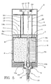
- the dispenser device 1 comprises an ejection member 12 acting on cartridges 6 ( Fig. 5 ).
- the ejection member 12 comprises a pusher 13 put into contact with pistons 11 to force the pistons 11 themselves forward.
- pusher 13 comprises two rods 14a, 14b each in contact with a respective piston 11.
- the ejection member 12 further comprises a motor 15 to drive pusher 13 and therefore pistons 11 in motion.
- motor 15 and pusher 13 are made through a worm screw 16 and a lead nut associated with rods the 14a, 14b.
- Mixer 17 associable with the dispenser device 1 is of the disposable type. In fact, once dispensing of the substance has been carried out, a portion of the already mixed substance intended for cross-linking remains inside mixer 7. The subsequent substance dispensing can only take place by replacing mixer 7.
- mixer 7 is of the combined dynamic-static type and comprises a dispensing nozzle 8 to be coupled with the dispenser device 1 at the second portion 5b of the receiving seat 5.
- a propeller 19 Coaxially disposed at the inside of nozzle 8 is a propeller 19 that, suitably set in rotation, promotes mixing of the components.
- the dispenser device 1 comprises actuating means 20 for movement of propeller 19, which means comprises a motor 21, a possible reduction gear (not shown in the figures) and a shaft 22 to be fitted into propeller 19 to drive it in rotation.
- Shaft 22 has a shaped cross section to form an integrally-rotating coupling between shaft 22 and propeller 19.
- shaft 22 has a hexagonal cross section.
- the dispenser device 1 further comprises drive means 23 associated with the ejection member 12 to operate dispensing of the substance.
- the drive means 23 acts on motor 15 of the ejection member'12 to actuate pusher 13.
- Said drive means 23 also acts on motor 21 of the actuating means 20 of mixer 7 to move propeller 19.
- operation of motor 15 of the ejection member 12 is simultaneous with operation of motor 21 of the actuating means 20 of mixer 7.
- the drive means 23 comprises a button 24 advantageously' disposed on the upper surface 2a of the supporting structure 2.
- the dispenser device is such designed as to be of the modular type, i.e. dispenser 1 can be associated with a desired number of further identical dispensers without particular interventions or modifications of the supporting structure 2a being required.
- the dispenser device 1 comprises coupling means 25 disposed on the supporting structure 2 to enable steady coupling of the dispenser device 1 with a further dispensing device.
- the supporting structure 2 comprises a first 26 and a second 27 side wall facing each other.
- the coupling means 25 is disposed on the first 26 and second 27 side walls in such a manner that the first 26 or second 27 side wall of the dispenser device 1 will be associable with the corresponding second 27 or first 26 side wall of a further adjacent dispenser device.
- first 26 and second 27 side walls have respective outer surfaces 26a, 27a mutually conforming in shape, so that the dispenser device 1 can be easily associated with another dispenser device disposed in side by side relationship therewith.
- the dispenser device 1 has no manual-access commands disposed on the first 26 and/or second side walls 27. Consequently, the dispenser device 1 can be associated with another dispenser device by placing the first 26 and second 27 side walls in side by side relationship. Therefore it is not possible to place commands at the side walls 26, 27 because an approached arrangement of the dispenser devices precludes lateral access to the devices themselves.
- all commands, transmissions for operation are inside, or on the upper part of, the device so that they do not interfere when several devices are to be coupled in a modular manner.
- the coupling means 25 comprises at least one hook 28 disposed on the first 26 or second 27 side wall and a corresponding slot 29 disposed on the second 27 or first side wall 26 at a position in register with hook 28.
- the dispenser device 1 comprises two hooks 28 formed on the first side wall 26 and two corresponding slots 29 disposed on the second side wall 27.
- hooks 28 and slots 29 are formed integrally with the first 26 and second 27 side walls, in known manner.
- hooks 28 and slots 29 can be made by a bending and/or punching operation.
- each hook 28 houses in the respective slot 29.
- first 28 and second 29 side walls have respective openings in mutual alignment.
- the coupling means 25 comprises a hooking element 31 to be engaged in the respective openings 30 in the first 26 and second 27 side walls.
- this hooking element 31 is insertable in the opening 30 formed in the first side wall 26 of the dispenser device 1 and in the opening 30 formed in the second side wall 27 of another dispenser device.
- the dispenser device 1 comprises two openings 30 formed in each first 26 and second 27 side wall in such a manner as to be aligned two by two.
- the hooking element 31 comprises a central portion 31a adapted to be engaged by a tool to move the hooking element 28 during a step of associating the dispenser device 1 with another dispenser device 1, and two end portions 31b insertable into openings 30.
- openings 30 in a first configuration enable entry of the end portions 31b into the supporting structure 2 and in a second configuration prevent exit of the end portions 31b, so that the dispenser device 1 can be maintained steadily associated with another dispenser device disposed in side by side relationship therewith.
- the shape of the end portions 31b matches the shape of openings 30 into which the former must be introduced.
- the adopted embodiment for the hooking means is not essential and therefore it can be different from that shown, provided the set does not lose its modular character, i.e. provided engagement of any number of identical dispenser devices is allowed.
- the dispenser device 1 can further comprise means 32 for electric connection to allow electrical connection of the dispenser device 1 with another dispenser device associated therewith.
- the electric-connection means 32 comprises a male connector 33 disposed on the first side wall 26 for example, and a female connector 34 placed on the second side wall 27.
- the dispenser device 1 further comprises a lateral finish body 36 that can be placed over the coupling means 25 to conceal it.
- this lateral finish body 36 is adapted to cover the coupling means 25 that is not used and that therefore would be in sight, when a dispenser device 1 is associated with another dispensing device.
- the lateral finish body 36 comprises panels 37 adapted to be superposed on the first 26 and/or the second side wall 27; these panels possibly can be painted or at all events personalised to give the dispenser the desired aesthetic appearance.
- each module will be provided with the respective self-supporting structure 2, while the lateral finish bodies 36 or aesthetic shells will have to be alternatively applied to the sides of a single dispenser or the sides of several coupled dispensers forming the module.
- the invention can further form a set 38 comprising a predetermined number of the above described dispenser devices 1 ( Fig. 6 ).
- dispenser devices 1 are disposed side by side in such a manner that the first side wall 26 of a dispenser 1 is coupled with the second side wall 27 of an adjacent dispenser 1 through the described coupling means 25.
- Set 38 further comprises a support 39 to bear the plurality of dispenser devices 1 associated with each other.
- support 39 can comprise a plurality of feet 40 mutually connected by a suitable frame 41 on which the plurality of dispenser devices 1 rests.
- support 39 comprises a hook (not shown in the figures) to hang the set 38 of dispensers on a wall.
- set 38 further comprises said power supply 35 to electrically feed the dispenser devices 1.
- set 38 comprises said lateral finish body 36 covering the unused coupling means 25.
- the lateral finish body 36 comprises panels 37 adapted to be superposed on the second wall 27 of the first dispenser device 1 and the first side wall 26 of the last dispenser device 1.
- the invention reaches the intended purposes and achieves important advantages.
- dispenser devices 1 constitute a single body easily movable depending on requirements.
- the presence of the electric-connection means 32 enables use of a single power supply 35 capable of feeding all the dispenser devices 1 associated with each other with electric energy. This too allows simpler use and space economy.
- the lateral finish body 36 allows the unused coupling means 25 to be covered thus achieving an improved aesthetic effect. It is also possible to provide a plurality of lateral finish bodies 36 differently decorated to adapt them to the harmony of the room where the dispenser device 1 or set 38 are to be used.
- the system is very versatile because if only one device is first purchased, other devices can be added also later on, depending on requirements.
Landscapes
- Health & Medical Sciences (AREA)
- General Health & Medical Sciences (AREA)
- Animal Behavior & Ethology (AREA)
- Oral & Maxillofacial Surgery (AREA)
- Dentistry (AREA)
- Epidemiology (AREA)
- Life Sciences & Earth Sciences (AREA)
- Public Health (AREA)
- Veterinary Medicine (AREA)
- Engineering & Computer Science (AREA)
- Mechanical Engineering (AREA)
- Coating Apparatus (AREA)
- External Artificial Organs (AREA)
- Sampling And Sample Adjustment (AREA)
- Nozzles (AREA)
- Feeding, Discharge, Calcimining, Fusing, And Gas-Generation Devices (AREA)
Abstract
Description
- The present invention relates to a dispenser device for bi-component substances. In particular, the present invention applies to odontology, for preparing and dispensing materials for dental impressions, silicones or others, formed with two distinct components.
- In more detail, these substances are made up of a cross-linkable material and a cross-linking agent that must remain separated before use. Mixing of the two components gives rise to cross-linking of the mixed material within a predetermined period of time. The components therefore must be mixed together just before use.
- The dispenser devices for bi-component substances of known type comprise a supporting body in which a receiving seat for a cartridge containing the two components of the substance to be mixed is formed.
- These dispenser devices also comprise means designed to cause discharge of she components from the cartridge into a mixer the task of which is to mix the two components so as to generate a homogeneous composition. This means generally consists of a piston acting on a moving wall of the cartridge in order to reduce volume of same and cause dispensing of the substance.
- Mixers are of the disposable type and can be static or dynamic. Static mixers comprise a dispensing nozzle and a fixed mixing element which is suitably shaped so as to promote mixing of the components. Dynamic mixers on the contrary comprise a propeller contained in the dispensing nozzle and set in rotation by a respective motor. Document
DE-U-84 35 167 shows the features of the preamble ofclaims 1 and 10. - It is to be noted that the dispenser devices for bi-component substances are such conceived as to hold only one pair of components each time, to dispense the desired material for dental impressions, for example. However, frequently two different mixed bi-component substances are to be used during a single dental treatment session.
- For instance, for obtaining a dental impression it is sometimes necessary to use a high viscosity material (termed tray material) together with a low viscosity material (termed lowering material).
- In this case, the operator must be able to replace one cartridge with another in a very quick manner and in any case before the cross-linking reaction of the first-dispensed substance may occur.
- Since this operation is very uncomfortable and delicate, in dentists' surgeries there is often the presence of two or more identical dispenser devices each designed to a different bi-component substance.
- Disadvantageously, availability of a plurality of distinct dispenser devices involves great bulkiness. In addition, use of distinct dispenser devices is expensive and unpractical.
- Within this context, the technical task of the present invention is to propose a dispenser device for bi-component substances that is without the mentioned drawbacks.
- In particular, the present invention aims at proposing a dispenser device for bi-component substances having reduced bulkiness and increased compactness.
- In addition, the invention aims at proposing a dispenser device that can be easily transported and controlled in a simple manner.
- It is a further aim of the invention to propose a dispenser device for bi-component substances with an improved aesthetic appearance and adapted to be personalised.
- In accordance with the present invention, the technical task and the aims herein described are achieved by a dispenser device for bi-component substances comprising the technical features set out in one or more of the appended claims.
- Further features and advantages of the present invention will become more apparent from the detailed description of a preferred but not exclusive embodiment of a dispenser device for bi-component substances given by way of non-limiting example, as illustrated in the accompanying drawings in which:
-
Figs. 1a and1b show respective perspective views of a first embodiment of a dispenser device for bi-component substances according to the present invention; -
Fig. 2 is a section view.of a detail of the dispenser device seen inFigs. 1a and1b ; -
Figs. 3a and3b show respective perspective views of a second embodiment of the dispenser device for bi-component substances according to the present invention; -
Fig. 4 shows a perspective view of a detail of the dispenser device seen inFigs. 3a and3b ; -
Fig. 5 shows a section view of the dispenser device according to the present invention; -
Fig. 6 is a perspective view of a set of dispenser devices for bi-component substances according to the present invention. - With reference to the drawings, a dispenser device for bi-component substances in accordance with the present invention has been generally identified with
reference numeral 1. - The
dispenser device 1 .comprises a supportingstructure 2 having abase 3 and aholding body 4 fastened to the base and disposed with its major extension axis inclined to a horizontal reference. - Formed in the supporting
structure 2 is a receivingseat 5 to house at least twocartridges 6 containing respective components of said substance and amixer 7 adapted to homogeneously mix and amalgamate the two components.Cartridges 6 can be separated and distinct or, alternatively, can be of one piece construction with a single supporting structure. - In detail, a
first portion 5a of thereceiving seat 5 is formed in theholding body 4 to receivecartridges 6 and asecond portion 5b of the receivingseat 5 is formed in alower wall 8 of the supportingstructure 2 to receivemixer 7. - The
dispenser device 1 comprises a door orhatch 9 disposed in anupper surface 2a of the supportingstructure 2. Thishatch 9 allows access to thefirst portion 5a of thereceiving seat 5 for introducing or removingcartridges 6. -
Cartridges 6 are in fluid communication withmixer 7 to enable the components to be transferred thereinto. In detail, formed in thelower wall 8 of the supportingstructure 2 areducts respective cartridge 6 tomixer 7. -
Cartridges 6 further have a respectivemovable piston 11 disposed in the vicinity of therespective end 6a of eachdistal cartridge 6 relative tomixer 7. Pistons 11 are movable close tomixer 7 to force the components into themixer 7 itself. - To this aim, the
dispenser device 1 comprises anejection member 12 acting on cartridges 6 (Fig. 5 ). In detail, theejection member 12 comprises apusher 13 put into contact withpistons 11 to force thepistons 11 themselves forward. - In the described embodiment,
pusher 13 comprises tworods respective piston 11. - The
ejection member 12 further comprises amotor 15 to drivepusher 13 and therefore pistons 11 in motion. By way of example, coupling betweenmotor 15 andpusher 13 is made through aworm screw 16 and a lead nut associated with rods the 14a, 14b. -
Mixer 17 associable with thedispenser device 1 is of the disposable type. In fact, once dispensing of the substance has been carried out, a portion of the already mixed substance intended for cross-linking remains insidemixer 7. The subsequent substance dispensing can only take place by replacingmixer 7. - In the described embodiment,
mixer 7 is of the combined dynamic-static type and comprises a dispensingnozzle 8 to be coupled with thedispenser device 1 at thesecond portion 5b of the receivingseat 5. - Coaxially disposed at the inside of
nozzle 8 is apropeller 19 that, suitably set in rotation, promotes mixing of the components. - In detail, the
dispenser device 1 comprises actuating means 20 for movement ofpropeller 19, which means comprises amotor 21, a possible reduction gear (not shown in the figures) and ashaft 22 to be fitted intopropeller 19 to drive it in rotation. -
Shaft 22 has a shaped cross section to form an integrally-rotating coupling betweenshaft 22 andpropeller 19. By way of example,shaft 22 has a hexagonal cross section. - The
dispenser device 1 further comprises drive means 23 associated with theejection member 12 to operate dispensing of the substance. In particular, the drive means 23 acts onmotor 15 of the ejection member'12 to actuatepusher 13. Said drive means 23 also acts onmotor 21 of the actuating means 20 ofmixer 7 to movepropeller 19. - Preferably, operation of
motor 15 of theejection member 12 is simultaneous with operation ofmotor 21 of the actuating means 20 ofmixer 7. - The drive means 23 comprises a
button 24 advantageously' disposed on theupper surface 2a of the supportingstructure 2. In more detail, the dispenser device is such designed as to be of the modular type,i.e. dispenser 1 can be associated with a desired number of further identical dispensers without particular interventions or modifications of the supportingstructure 2a being required. - For the above purpose, the
dispenser device 1 comprises coupling means 25 disposed on the supportingstructure 2 to enable steady coupling of thedispenser device 1 with a further dispensing device. - The supporting
structure 2 comprises a first 26 and a second 27 side wall facing each other. In detail, the coupling means 25 is disposed on the first 26 and second 27 side walls in such a manner that the first 26 or second 27 side wall of thedispenser device 1 will be associable with the corresponding second 27 or first 26 side wall of a further adjacent dispenser device. - To this aim, it will be recognised that the first 26 and second 27 side walls have respective
outer surfaces dispenser device 1 can be easily associated with another dispenser device disposed in side by side relationship therewith. - It will be appreciated that advantageously the
dispenser device 1 has no manual-access commands disposed on the first 26 and/orsecond side walls 27. Consequently, thedispenser device 1 can be associated with another dispenser device by placing the first 26 and second 27 side walls in side by side relationship. Therefore it is not possible to place commands at theside walls - In this regard, all commands, transmissions for operation are inside, or on the upper part of, the device so that they do not interfere when several devices are to be coupled in a modular manner.
- In a first embodiment, the coupling means 25 comprises at least one
hook 28 disposed on the first 26 or second 27 side wall and acorresponding slot 29 disposed on the second 27 orfirst side wall 26 at a position in register withhook 28. - In the embodiment shown in
Figs. 1a and1b , thedispenser device 1 comprises twohooks 28 formed on thefirst side wall 26 and twocorresponding slots 29 disposed on thesecond side wall 27. - Preferably, hooks 28 and
slots 29 are formed integrally with the first 26 and second 27 side walls, in known manner. For instance, hooks 28 andslots 29 can be made by a bending and/or punching operation. - With reference to
Fig. 3 , in a coupled configuration eachhook 28 houses in therespective slot 29. - In a second embodiment, the first 28 and second 29 side walls have respective openings in mutual alignment. In this case, the coupling means 25 comprises a hooking
element 31 to be engaged in therespective openings 30 in the first 26 and second 27 side walls. - In detail, this hooking
element 31 is insertable in theopening 30 formed in thefirst side wall 26 of thedispenser device 1 and in theopening 30 formed in thesecond side wall 27 of another dispenser device. - In the embodiment shown in
Figs. 3a and3b , thedispenser device 1 comprises twoopenings 30 formed in each first 26 and second 27 side wall in such a manner as to be aligned two by two. - With particular reference to
Fig. 4 , the hookingelement 31 comprises acentral portion 31a adapted to be engaged by a tool to move the hookingelement 28 during a step of associating thedispenser device 1 with anotherdispenser device 1, and twoend portions 31b insertable intoopenings 30. - In particular,
openings 30 in a first configuration enable entry of theend portions 31b into the supportingstructure 2 and in a second configuration prevent exit of theend portions 31b, so that thedispenser device 1 can be maintained steadily associated with another dispenser device disposed in side by side relationship therewith. In other words, the shape of theend portions 31b matches the shape ofopenings 30 into which the former must be introduced. - It will be understood that the adopted embodiment for the hooking means is not essential and therefore it can be different from that shown, provided the set does not lose its modular character, i.e. provided engagement of any number of identical dispenser devices is allowed.
- The
dispenser device 1 can further comprise means 32 for electric connection to allow electrical connection of thedispenser device 1 with another dispenser device associated therewith. - In detail, the electric-connection means 32 comprises a
male connector 33 disposed on thefirst side wall 26 for example, and afemale connector 34 placed on thesecond side wall 27. - In this manner, as better clarified in the following, it will be possible to associate two or
more dispenser devices 1 by disposing them in mutual side by side relationship and powering them with only oneexternal power supply 35. - The
dispenser device 1 further comprises alateral finish body 36 that can be placed over the coupling means 25 to conceal it. In particular, thislateral finish body 36 is adapted to cover the coupling means 25 that is not used and that therefore would be in sight, when adispenser device 1 is associated with another dispensing device. - In detail, the
lateral finish body 36 comprisespanels 37 adapted to be superposed on the first 26 and/or thesecond side wall 27; these panels possibly can be painted or at all events personalised to give the dispenser the desired aesthetic appearance. In other words, each module will be provided with the respective self-supportingstructure 2, while thelateral finish bodies 36 or aesthetic shells will have to be alternatively applied to the sides of a single dispenser or the sides of several coupled dispensers forming the module. - The invention can further form a
set 38 comprising a predetermined number of the above described dispenser devices 1 (Fig. 6 ). - In particular, the
dispenser devices 1 are disposed side by side in such a manner that thefirst side wall 26 of adispenser 1 is coupled with thesecond side wall 27 of anadjacent dispenser 1 through the described coupling means 25. -
Set 38 further comprises asupport 39 to bear the plurality ofdispenser devices 1 associated with each other. In particular, by way of example,support 39 can comprise a plurality offeet 40 mutually connected by asuitable frame 41 on which the plurality ofdispenser devices 1 rests. - In an alternative embodiment,
support 39 comprises a hook (not shown in the figures) to hang theset 38 of dispensers on a wall. - As mentioned above, set 38 further comprises said
power supply 35 to electrically feed thedispenser devices 1. - It will be appreciated that for
set 38 only onepower supply 35 is required which is connected to one alone of saiddispenser devices 1. In fact, alldispenser devices 1 are electrically connected by the above mentioned electric-connection means 32. - In addition, set 38 comprises said
lateral finish body 36 covering the unused coupling means 25. In particular, thelateral finish body 36 comprisespanels 37 adapted to be superposed on thesecond wall 27 of thefirst dispenser device 1 and thefirst side wall 26 of thelast dispenser device 1. - The invention reaches the intended purposes and achieves important advantages.
- First of all, it is possible to steadily associate a predetermined number of
dispenser devices 1 in such a manner that each lies side by side with, and connected to the adjacent one. - This allows an important space to be saved and more comfort to be reached because the
dispenser devices 1 constitute a single body easily movable depending on requirements. - It is also to be pointed out that the presence of the electric-connection means 32 enables use of a
single power supply 35 capable of feeding all thedispenser devices 1 associated with each other with electric energy. This too allows simpler use and space economy. - In addition, the
lateral finish body 36 allows the unused coupling means 25 to be covered thus achieving an improved aesthetic effect. It is also possible to provide a plurality oflateral finish bodies 36 differently decorated to adapt them to the harmony of the room where thedispenser device 1 or set 38 are to be used. - In case of damage of one of said finish bodies, the same can be replaced in a very simple manner and with very low costs.
- In addition, the system is very versatile because if only one device is first purchased, other devices can be added also later on, depending on requirements.
Claims (16)
- A dispenser device for bi-component substances comprising:- a supporting structure (2);- a receiving seat (5) formed inside said supporting structure (2) and in which at least two cartridges (6) can be housed, each of them containing one respective component of a substance to be mixed, as well as a mixer (7) in fluid communication with said cartridges (6), in order to mix said components;- an ejection member (12) capable of acting on both the cartridges (6) to enable dispensing of said components; said dispenser device being characterised in that it is a modular type dispenser device further comprising coupling means (25) disposed on said supporting structure (2) to allow steady coupling of said dispenser device with another dispenser device,in that said supporting structure (2) is provided with a first (26) and a second (27) side wall which are substantially opposite to each other; said coupling means (25) being associated with said first (26) and/or second (27) side walls of said supporting structure (2) to steadily couple said first (26) or second (27) side wall of said dispenser device with said second (27) or first (26) side wall of another dispenser device,
in that it further comprises electric-connection means (32) to electrically connect said dispenser device to another dispenser device, and in that said connection means (32) comprises a male connector (33) disposed on said first side wall (26) and a female connector (34) disposed on said second side wall (27) whereby it will be possible to associate two or more dispenser devices (1) by disposing them in mutual side by side relationship and powering them with only one external power supply (35). - A dispenser device as claimed in claim 1, characterised in that said first (26) and second (27) side walls have substantially matching respective outer surfaces (26a, 27a) and characterised in that said first (26) and second (27) side walls are without manual-access command members.
- A dispenser device as claimed in anyone of claims 1 to 2, characterised in that it further comprises a lateral finish body (36) that can be superposed on said coupling means (25) and preferably on said first (26) and second (27) side walls to conceal the latter and preferably characterised in that said covering body (36) comprises at least one panel (37) adapted to be superposed on said first (26) and/or second (27) side wall.
- A dispenser device as claimed in anyone of claims 1 to 3, characterised in that the coupling means (25) comprises at least one hook (28) associated with said first side wall (26) and a slot (29) made on said second side wall (27) at a position corresponding to said hook (28); said slot (29) being adapted to receive said hook (28) of another dispenser device.
- A dispenser device as claimed in claim 4, characterised in that said hook (28) and slot (29) are made integrally with said first (26) and second (27) side walls by a bending and/or punching operation.
- A dispenser device as claimed in claim 4 or 5, characterised in that it comprises a plurality of said hooks (28) and a corresponding plurality of said slots (29).
- A dispenser device as claimed in anyone of claims 1 to 6, characterised in that said first (26) and second (27) side walls have respective openings (30) preferably aligned with each other; said coupling means (25) comprising at least one hooking element (31) intended for engagement in said opening (31) of said first side wall (26) and in said opening (30) of said second wall (27) of another dispenser device.
- A dispenser device as claimed in claim 7, characterised in that said hooking element (31) comprises a central portion (31a) and two shaped end portions (31b) adapted to be inserted into said openings (30) to keep said dispenser device associated with another dispenser device.
- A dispenser device as claimed in claim 8, characterised in that said openings (30) in a first operating configuration enable access of said shaped end portions (31b) to the inside of said supporting structure (2) and in a second operating configuration prevent exit of said end portions (31b).
- A set comprising a predetermined number of at least two identical dispenser devices, each characterised by:- a supporting structure (2);- a receiving seat (5) formed inside said supporting structure (2) and in which at least two cartridges (6) can be housed, each of them containing one respective component of a substance to be mixed as well as a mixer (7) in fluid communication with said cartridges (6) in order to mix said components;- an ejection member (12) capable of acting on both the cartridges (6) to enable dispensing of said components;- each dispenser device in the set being a modular type dispenser device steadily coupled with another dispenser device of the set through coupling means (25) associated with each supporting structure (2).
- A set as claimed in claim 10, characterised in that each supporting structure (2) comprises a first (26) and a second (27) side wall facing each other; each first wall (26) of a dispenser device being associated with each second wall (27) of a subsequent dispenser device.
- A set as claimed in claim 10 or 11, characterised in that it comprises a single support (39) to bear said dispenser devices.
- A set as claimed in claim 12, characterised in that said support (39) comprises a hook to fix said set to a wall.
- A set as claimed in anyone of claims 10 to 13, characterised in that each dispenser device comprises electric-connection means (32) to connect each dispenser device to an adjacent dispenser device and only one external power supply (35) whereby it will be possible to associate two or more dispenser devices (1) by disposing them in mutual side by side relationship and powering them with the only one external supply (35).
- A set as claimed in claim 14, characterised in that said connection means (32) of each dispenser device comprises a male connector (33) disposed on said first side wall (26) and a female connector (34) disposed on said second side wall (27), the male connector (33) of a dispenser device being suitable for being associated to a female connector of an adjacent dispenser device and the female connector (33) of a dispenser device being suitable for being associated to a male connector of an adjacent dispenser device, and said power supply (35) electrically feeding all the dispenser devices of the set.
- A set as claimed in anyone of claims 10 to 15, characterised in that it further comprises a lateral finish body (36) associated with a first one and a last one of said dispenser devices and adapted to be superposed on said coupling means (25),and preferably characterised in that said lateral finish body (36) comprises panels (37) adapted to be superposed on said second side wall (27) of said first dispenser device and on said first side wall (26) of said last dispenser device.
Priority Applications (2)
| Application Number | Priority Date | Filing Date | Title |
|---|---|---|---|
| SI200730723T SI2209561T1 (en) | 2007-11-12 | 2007-11-12 | Dispenser device for bi-component substances |
| PL07866759T PL2209561T3 (en) | 2007-11-12 | 2007-11-12 | Dispenser device for bi-component substances |
Applications Claiming Priority (1)
| Application Number | Priority Date | Filing Date | Title |
|---|---|---|---|
| PCT/IT2007/000796 WO2009063509A1 (en) | 2007-11-12 | 2007-11-12 | Dispenser device for bi-component substances |
Publications (2)
| Publication Number | Publication Date |
|---|---|
| EP2209561A1 EP2209561A1 (en) | 2010-07-28 |
| EP2209561B1 true EP2209561B1 (en) | 2011-07-13 |
Family
ID=39650610
Family Applications (1)
| Application Number | Title | Priority Date | Filing Date |
|---|---|---|---|
| EP07866759A Active EP2209561B1 (en) | 2007-11-12 | 2007-11-12 | Dispenser device for bi-component substances |
Country Status (11)
| Country | Link |
|---|---|
| US (1) | US20100252574A1 (en) |
| EP (1) | EP2209561B1 (en) |
| CN (1) | CN101855025B (en) |
| AT (1) | ATE516087T1 (en) |
| DK (1) | DK2209561T3 (en) |
| ES (1) | ES2367834T3 (en) |
| IL (1) | IL205342A0 (en) |
| PL (1) | PL2209561T3 (en) |
| PT (1) | PT2209561E (en) |
| SI (1) | SI2209561T1 (en) |
| WO (1) | WO2009063509A1 (en) |
Cited By (1)
| Publication number | Priority date | Publication date | Assignee | Title |
|---|---|---|---|---|
| EP4198322A1 (en) | 2021-12-15 | 2023-06-21 | Erbe Elektromedizin GmbH | Rotary connector |
Families Citing this family (23)
| Publication number | Priority date | Publication date | Assignee | Title |
|---|---|---|---|---|
| WO2004080611A1 (en) * | 2003-03-06 | 2004-09-23 | Dentsply International Inc. | Dispensing and mixing tip |
| DE202005005833U1 (en) * | 2005-02-25 | 2005-06-23 | Vosschemie Gmbh | Dispenser and mixer for two component reactive resin-fillers e.g. for repair of automobile bodywork |
| DE102006038897B4 (en) * | 2006-08-18 | 2014-10-16 | Mühlbauer Technology Gmbh | Apparatus for generating a multicomponent mass |
| KR100894889B1 (en) * | 2007-12-17 | 2009-04-30 | 삼성전기주식회사 | Discharge device with stirring function |
| DE102009049285A1 (en) * | 2009-10-13 | 2011-05-05 | Heraeus Kulzer Gmbh | One-pack for dental mixing device |
| EP2324794A1 (en) | 2009-11-20 | 2011-05-25 | 3M Innovative Properties Company | A device for dispensing a dental composition |
| EP2324792A1 (en) * | 2009-11-20 | 2011-05-25 | 3M Innovative Properties Company | A device for dispensing a material |
| DE102010062798A1 (en) * | 2010-12-10 | 2012-06-14 | Krones Aktiengesellschaft | Blender for a beverage bottling plant |
| EP2468416A1 (en) * | 2010-12-24 | 2012-06-27 | Sika Technology AG | Application device for multi-pack products, cartridge set and packaging unit |
| WO2012151295A2 (en) | 2011-05-02 | 2012-11-08 | Mouse Trap Design, Llc | Mixing and dispensing device |
| US8881945B2 (en) | 2011-09-19 | 2014-11-11 | S.C. Johnson & Son, Inc. | Spray dispenser |
| US20140036616A1 (en) * | 2012-08-04 | 2014-02-06 | Common Sense, Llc | Dispensing and mixing systems |
| US9108782B2 (en) | 2012-10-15 | 2015-08-18 | S.C. Johnson & Son, Inc. | Dispensing systems with improved sensing capabilities |
| KR101406068B1 (en) * | 2013-09-05 | 2014-06-11 | (주)디엑스엠 | Impression mixing tip |
| WO2015070097A1 (en) | 2013-11-07 | 2015-05-14 | Mouse Trap Design, Llc | Mixing and dispensing device |
| DE202014001720U1 (en) * | 2014-02-27 | 2015-03-02 | Gerhard Brugger | donor |
| EP2923774B1 (en) | 2014-03-24 | 2019-02-13 | Sulzer Mixpac AG | Dispenser |
| GB2530476A (en) | 2014-07-15 | 2016-03-30 | Cox Ltd | Multicomponent dispenser |
| WO2017134438A1 (en) * | 2016-02-05 | 2017-08-10 | Bae Systems Plc | End effector for a robot |
| US10981185B2 (en) * | 2016-08-13 | 2021-04-20 | Nordson Corporation | Systems and methods for two-component mixing in a jetting dispenser |
| KR101800249B1 (en) * | 2016-12-23 | 2017-12-20 | 주식회사 티앤알바이오팹 | Mixing Device for Cell-printing Composition |
| DE102017112440A1 (en) * | 2017-06-06 | 2018-12-06 | Shin-Etsu Silicones Europe B.V. | Container and dosing device for viscous materials |
| DE102017124665A1 (en) * | 2017-10-23 | 2019-04-25 | Endress+Hauser Flowtec Ag | Method for producing a printed circuit board provided with at least one coating and painting head for carrying out the method |
Family Cites Families (29)
| Publication number | Priority date | Publication date | Assignee | Title |
|---|---|---|---|---|
| US3872593A (en) * | 1965-10-20 | 1975-03-25 | Dentsply Research Dev Corp | Dental console |
| US3857619A (en) * | 1974-02-08 | 1974-12-31 | Texstar Corp | Modular cabinet system |
| SE383602B (en) * | 1974-03-25 | 1976-03-22 | J A Hallen | SERVICE UNIT, IN PARTICULAR FOR TOYS OR DENTAL RECEPTIONS AND OPERATING ROOMS |
| US4106828A (en) * | 1977-02-14 | 1978-08-15 | Belokin Jr Paul | Display fixture |
| US4135775A (en) * | 1977-06-20 | 1979-01-23 | Steelcase Inc. | Movable divider panels with electrical wiring |
| DE2733310A1 (en) * | 1977-07-23 | 1979-02-08 | Oskar Vaupel | Pasty material extrusion equipment - has cylindrical tube with cartridge compression spring and spray nozzle with valve |
| US4433881A (en) * | 1981-11-16 | 1984-02-28 | Datapoint Corporation | Connecting mechanism for word processor - controlled printer output module cabinets |
| DE8435167U1 (en) * | 1984-11-30 | 1985-04-18 | Cornils, Gerd, 5161 Girbelsrath | Device for emptying cartridges |
| US5390825A (en) * | 1993-03-10 | 1995-02-21 | Rockel; Christopher M. | Portable, self contained, two-part adhesive dispensing device |
| US5553935A (en) * | 1993-10-20 | 1996-09-10 | Elkay Manufacturing Company | Cabinet and supporting frame for liquid dispensing system |
| JP3298493B2 (en) * | 1997-03-18 | 2002-07-02 | 株式会社デンソー | Heat exchanger for vehicle heating |
| US6089884A (en) * | 1997-07-10 | 2000-07-18 | Dal Partnership | Track lighting system |
| KR100300642B1 (en) * | 1997-08-29 | 2001-09-06 | 오까다 마사하루 | Coin processing apparatus |
| US5842606A (en) * | 1997-09-30 | 1998-12-01 | Devito; Joseph A | Beverage server |
| US6655551B2 (en) * | 2000-11-03 | 2003-12-02 | Joseph Manne | Portable dispenser for mixing and dispensing fluid mixtures |
| US6616469B2 (en) * | 2001-03-12 | 2003-09-09 | Tyco Electronics Logistics Ag | Electrical and fluid interconnect |
| DE10112904C5 (en) * | 2001-03-15 | 2010-04-22 | 3M Espe Ag | Dynamic mixer and method for mixing at least two paste components |
| EP1279379B9 (en) * | 2001-07-26 | 2006-12-13 | Ernst Mühlbauer GmbH & Co.KG | Method and device for obtaining a multicomponent mass, especially for dental purposes |
| DE10146093A1 (en) * | 2001-09-19 | 2003-04-03 | Bosch Gmbh Robert | Electronic module, especially for use in motor vehicle, has first plug with which module can be plugged onto holder and second plug to which further electronic module can be connected |
| US6827212B2 (en) * | 2002-04-22 | 2004-12-07 | Brian K. Reaux | Surgical or medical instrument holder |
| EP1439009A1 (en) * | 2003-01-20 | 2004-07-21 | Paul Stämpfli | Glue dispenser |
| EP1510248B1 (en) * | 2003-08-14 | 2005-06-08 | 3M Espe Ag | Mixer element for a mixer for multi-component pastes, and mixer using the same |
| US20050103809A1 (en) * | 2003-11-13 | 2005-05-19 | Mixpac Systems Ag | Electrically operated cartridge dispensing appliance |
| ITMI20030588U1 (en) * | 2003-12-12 | 2005-06-13 | Reggiani Fulvio | CONTAINER FOR THE DISTRIBUTION OF DISTINCT PRODUCTS |
| US6938966B1 (en) * | 2004-03-12 | 2005-09-06 | Kevin Rouwhorst | Cabinet connector |
| NL1027731C2 (en) * | 2004-12-13 | 2006-06-14 | Zandbergen Ind Plaatwerk | Fixing element for fixing panels to each other as well as a cabinet with panels connected by such a fixing element. |
| US7140797B2 (en) * | 2005-02-18 | 2006-11-28 | Plas-Pak Industries, Inc. | Multi-cartridge dispenser |
| EP1700639A1 (en) * | 2005-03-11 | 2006-09-13 | 3M Innovative Properties Company | Dispensing device |
| US7712635B2 (en) * | 2005-06-21 | 2010-05-11 | Kovac Karen S | Quick load caulking gun cartridge holder |
-
2007
- 2007-11-12 SI SI200730723T patent/SI2209561T1/en unknown
- 2007-11-12 PT PT07866759T patent/PT2209561E/en unknown
- 2007-11-12 AT AT07866759T patent/ATE516087T1/en active
- 2007-11-12 US US12/742,202 patent/US20100252574A1/en not_active Abandoned
- 2007-11-12 ES ES07866759T patent/ES2367834T3/en active Active
- 2007-11-12 DK DK07866759.9T patent/DK2209561T3/en active
- 2007-11-12 CN CN2007801015074A patent/CN101855025B/en not_active Expired - Fee Related
- 2007-11-12 PL PL07866759T patent/PL2209561T3/en unknown
- 2007-11-12 WO PCT/IT2007/000796 patent/WO2009063509A1/en not_active Ceased
- 2007-11-12 EP EP07866759A patent/EP2209561B1/en active Active
-
2010
- 2010-04-26 IL IL205342A patent/IL205342A0/en unknown
Cited By (1)
| Publication number | Priority date | Publication date | Assignee | Title |
|---|---|---|---|---|
| EP4198322A1 (en) | 2021-12-15 | 2023-06-21 | Erbe Elektromedizin GmbH | Rotary connector |
Also Published As
| Publication number | Publication date |
|---|---|
| ATE516087T1 (en) | 2011-07-15 |
| CN101855025A (en) | 2010-10-06 |
| US20100252574A1 (en) | 2010-10-07 |
| PL2209561T3 (en) | 2011-12-30 |
| ES2367834T3 (en) | 2011-11-08 |
| DK2209561T3 (en) | 2011-10-24 |
| IL205342A0 (en) | 2010-12-30 |
| EP2209561A1 (en) | 2010-07-28 |
| WO2009063509A1 (en) | 2009-05-22 |
| SI2209561T1 (en) | 2011-10-28 |
| PT2209561E (en) | 2011-09-12 |
| CN101855025B (en) | 2012-12-05 |
Similar Documents
| Publication | Publication Date | Title |
|---|---|---|
| EP2209561B1 (en) | Dispenser device for bi-component substances | |
| EP2018132B1 (en) | Dispensing device with a spray assembly | |
| EP1825927A3 (en) | Unit-dose syringe for a multi-component material | |
| US10947743B2 (en) | System and method for applying a tile adhesive | |
| WO2007121003A3 (en) | Dispenser and method for dispensing dental material | |
| WO2006023340A3 (en) | A scented material dispense system for a hand-held device | |
| AU7496094A (en) | Device for conching chocolate compound | |
| CN108973683B (en) | Individualized and modular instrument board assembly and car | |
| CN101099284A (en) | Method of mixing and extruding viscous material and gearbox for dispensing the same | |
| WO2002053058A8 (en) | Method and device for a dental unit or unit intended for the human body | |
| AU2015301354B2 (en) | Multiple solid products liquid solution dispenser | |
| AU2005201047B2 (en) | Dental impression material kneading device | |
| EP1547505B1 (en) | Multifunctional metering device | |
| DE202013003475U1 (en) | Fahrzeugbeduftungsvorrichtung | |
| JP2004114039A (en) | Modular controller for a hot melt adhesive dispensing system | |
| CN110709157B (en) | fluid mixing device | |
| EP2011677B1 (en) | Device and method for perfuming the compartment of a vehicle | |
| TW201029601A (en) | Ejector unit and furniture | |
| AU2663301A (en) | Device for mixing viscous liquids | |
| DE102014012538A1 (en) | shower unit | |
| EP1602413A3 (en) | Spray booth with hybrid electrical heating | |
| ITTO20040892A1 (en) | PLANETARY MIXING MACHINE FOR FOODSTUFFS | |
| US20260014941A1 (en) | Trim component of or for a vehicle and vehicle comprising such a trim component | |
| EP2441413A1 (en) | A mixer for forming a dental material, a system comprising the mixer, and a method of mounting the mixer | |
| CN117618770A (en) | Beauty instrument |
Legal Events
| Date | Code | Title | Description |
|---|---|---|---|
| PUAI | Public reference made under article 153(3) epc to a published international application that has entered the european phase |
Free format text: ORIGINAL CODE: 0009012 |
|
| 17P | Request for examination filed |
Effective date: 20100429 |
|
| AK | Designated contracting states |
Kind code of ref document: A1 Designated state(s): AT BE BG CH CY CZ DE DK EE ES FI FR GB GR HU IE IS IT LI LT LU LV MC MT NL PL PT RO SE SI SK TR |
|
| AX | Request for extension of the european patent |
Extension state: AL BA HR MK RS |
|
| GRAP | Despatch of communication of intention to grant a patent |
Free format text: ORIGINAL CODE: EPIDOSNIGR1 |
|
| GRAS | Grant fee paid |
Free format text: ORIGINAL CODE: EPIDOSNIGR3 |
|
| GRAA | (expected) grant |
Free format text: ORIGINAL CODE: 0009210 |
|
| AK | Designated contracting states |
Kind code of ref document: B1 Designated state(s): AT BE BG CH CY CZ DE DK EE ES FI FR GB GR HU IE IS IT LI LT LU LV MC MT NL PL PT RO SE SI SK TR |
|
| AX | Request for extension of the european patent |
Extension state: AL BA HR MK RS |
|
| REG | Reference to a national code |
Ref country code: GB Ref legal event code: FG4D |
|
| REG | Reference to a national code |
Ref country code: CH Ref legal event code: EP |
|
| REG | Reference to a national code |
Ref country code: CH Ref legal event code: NV Representative=s name: BUGNION S.A. |
|
| REG | Reference to a national code |
Ref country code: IE Ref legal event code: FG4D |
|
| REG | Reference to a national code |
Ref country code: SE Ref legal event code: TRGR |
|
| REG | Reference to a national code |
Ref country code: DE Ref legal event code: R096 Ref document number: 602007015854 Country of ref document: DE Effective date: 20110901 |
|
| REG | Reference to a national code |
Ref country code: NL Ref legal event code: T3 |
|
| REG | Reference to a national code |
Ref country code: PT Ref legal event code: SC4A Free format text: AVAILABILITY OF NATIONAL TRANSLATION Effective date: 20110905 |
|
| REG | Reference to a national code |
Ref country code: RO Ref legal event code: EPE |
|
| REG | Reference to a national code |
Ref country code: DK Ref legal event code: T3 |
|
| REG | Reference to a national code |
Ref country code: ES Ref legal event code: FG2A Ref document number: 2367834 Country of ref document: ES Kind code of ref document: T3 Effective date: 20111108 |
|
| REG | Reference to a national code |
Ref country code: GR Ref legal event code: EP Ref document number: 20110402219 Country of ref document: GR Effective date: 20111013 |
|
| REG | Reference to a national code |
Ref country code: HU Ref legal event code: AG4A Ref document number: E011698 Country of ref document: HU |
|
| REG | Reference to a national code |
Ref country code: SK Ref legal event code: T3 Ref document number: E 10190 Country of ref document: SK |
|
| REG | Reference to a national code |
Ref country code: PL Ref legal event code: T3 |
|
| PG25 | Lapsed in a contracting state [announced via postgrant information from national office to epo] |
Ref country code: LT Free format text: LAPSE BECAUSE OF FAILURE TO SUBMIT A TRANSLATION OF THE DESCRIPTION OR TO PAY THE FEE WITHIN THE PRESCRIBED TIME-LIMIT Effective date: 20110713 Ref country code: IS Free format text: LAPSE BECAUSE OF FAILURE TO SUBMIT A TRANSLATION OF THE DESCRIPTION OR TO PAY THE FEE WITHIN THE PRESCRIBED TIME-LIMIT Effective date: 20111113 |
|
| PG25 | Lapsed in a contracting state [announced via postgrant information from national office to epo] |
Ref country code: CY Free format text: LAPSE BECAUSE OF FAILURE TO SUBMIT A TRANSLATION OF THE DESCRIPTION OR TO PAY THE FEE WITHIN THE PRESCRIBED TIME-LIMIT Effective date: 20110713 Ref country code: LV Free format text: LAPSE BECAUSE OF FAILURE TO SUBMIT A TRANSLATION OF THE DESCRIPTION OR TO PAY THE FEE WITHIN THE PRESCRIBED TIME-LIMIT Effective date: 20110713 |
|
| PLBE | No opposition filed within time limit |
Free format text: ORIGINAL CODE: 0009261 |
|
| STAA | Information on the status of an ep patent application or granted ep patent |
Free format text: STATUS: NO OPPOSITION FILED WITHIN TIME LIMIT |
|
| PG25 | Lapsed in a contracting state [announced via postgrant information from national office to epo] |
Ref country code: EE Free format text: LAPSE BECAUSE OF FAILURE TO SUBMIT A TRANSLATION OF THE DESCRIPTION OR TO PAY THE FEE WITHIN THE PRESCRIBED TIME-LIMIT Effective date: 20110713 |
|
| 26N | No opposition filed |
Effective date: 20120416 |
|
| PG25 | Lapsed in a contracting state [announced via postgrant information from national office to epo] |
Ref country code: MC Free format text: LAPSE BECAUSE OF NON-PAYMENT OF DUE FEES Effective date: 20111130 |
|
| REG | Reference to a national code |
Ref country code: DE Ref legal event code: R097 Ref document number: 602007015854 Country of ref document: DE Effective date: 20120416 |
|
| REG | Reference to a national code |
Ref country code: IE Ref legal event code: MM4A |
|
| PG25 | Lapsed in a contracting state [announced via postgrant information from national office to epo] |
Ref country code: IE Free format text: LAPSE BECAUSE OF NON-PAYMENT OF DUE FEES Effective date: 20111112 |
|
| PG25 | Lapsed in a contracting state [announced via postgrant information from national office to epo] |
Ref country code: MT Free format text: LAPSE BECAUSE OF FAILURE TO SUBMIT A TRANSLATION OF THE DESCRIPTION OR TO PAY THE FEE WITHIN THE PRESCRIBED TIME-LIMIT Effective date: 20110713 |
|
| PGFP | Annual fee paid to national office [announced via postgrant information from national office to epo] |
Ref country code: DK Payment date: 20141126 Year of fee payment: 8 Ref country code: LU Payment date: 20141125 Year of fee payment: 8 |
|
| PGFP | Annual fee paid to national office [announced via postgrant information from national office to epo] |
Ref country code: CZ Payment date: 20141106 Year of fee payment: 8 Ref country code: TR Payment date: 20141027 Year of fee payment: 8 Ref country code: GB Payment date: 20141128 Year of fee payment: 8 Ref country code: BG Payment date: 20141029 Year of fee payment: 8 Ref country code: ES Payment date: 20141222 Year of fee payment: 8 Ref country code: FI Payment date: 20141124 Year of fee payment: 8 Ref country code: GR Payment date: 20141124 Year of fee payment: 8 Ref country code: SK Payment date: 20141110 Year of fee payment: 8 Ref country code: SE Payment date: 20141126 Year of fee payment: 8 Ref country code: CH Payment date: 20141126 Year of fee payment: 8 Ref country code: RO Payment date: 20141107 Year of fee payment: 8 |
|
| PGFP | Annual fee paid to national office [announced via postgrant information from national office to epo] |
Ref country code: FR Payment date: 20141126 Year of fee payment: 8 Ref country code: NL Payment date: 20141125 Year of fee payment: 8 Ref country code: PT Payment date: 20141030 Year of fee payment: 8 Ref country code: SI Payment date: 20141021 Year of fee payment: 8 Ref country code: AT Payment date: 20141126 Year of fee payment: 8 Ref country code: PL Payment date: 20141009 Year of fee payment: 8 |
|
| PGFP | Annual fee paid to national office [announced via postgrant information from national office to epo] |
Ref country code: IT Payment date: 20141128 Year of fee payment: 8 |
|
| PGFP | Annual fee paid to national office [announced via postgrant information from national office to epo] |
Ref country code: DE Payment date: 20150129 Year of fee payment: 8 Ref country code: HU Payment date: 20150210 Year of fee payment: 8 |
|
| PGFP | Annual fee paid to national office [announced via postgrant information from national office to epo] |
Ref country code: BE Payment date: 20141127 Year of fee payment: 8 |
|
| REG | Reference to a national code |
Ref country code: PT Ref legal event code: MM4A Free format text: LAPSE DUE TO NON-PAYMENT OF FEES Effective date: 20160512 |
|
| REG | Reference to a national code |
Ref country code: DE Ref legal event code: R119 Ref document number: 602007015854 Country of ref document: DE |
|
| REG | Reference to a national code |
Ref country code: DK Ref legal event code: EBP Effective date: 20151130 |
|
| PG25 | Lapsed in a contracting state [announced via postgrant information from national office to epo] |
Ref country code: LU Free format text: LAPSE BECAUSE OF NON-PAYMENT OF DUE FEES Effective date: 20151112 |
|
| REG | Reference to a national code |
Ref country code: CH Ref legal event code: PL |
|
| REG | Reference to a national code |
Ref country code: AT Ref legal event code: MM01 Ref document number: 516087 Country of ref document: AT Kind code of ref document: T Effective date: 20151112 |
|
| GBPC | Gb: european patent ceased through non-payment of renewal fee |
Effective date: 20151112 |
|
| PG25 | Lapsed in a contracting state [announced via postgrant information from national office to epo] |
Ref country code: GR Free format text: LAPSE BECAUSE OF NON-PAYMENT OF DUE FEES Effective date: 20160602 Ref country code: CZ Free format text: LAPSE BECAUSE OF NON-PAYMENT OF DUE FEES Effective date: 20151112 Ref country code: IT Free format text: LAPSE BECAUSE OF NON-PAYMENT OF DUE FEES Effective date: 20151112 Ref country code: LI Free format text: LAPSE BECAUSE OF NON-PAYMENT OF DUE FEES Effective date: 20151130 Ref country code: CH Free format text: LAPSE BECAUSE OF NON-PAYMENT OF DUE FEES Effective date: 20151130 |
|
| REG | Reference to a national code |
Ref country code: SK Ref legal event code: MM4A Ref document number: E 10190 Country of ref document: SK Effective date: 20151112 |
|
| REG | Reference to a national code |
Ref country code: NL Ref legal event code: MM Effective date: 20151201 |
|
| REG | Reference to a national code |
Ref country code: FR Ref legal event code: ST Effective date: 20160729 |
|
| PG25 | Lapsed in a contracting state [announced via postgrant information from national office to epo] |
Ref country code: RO Free format text: LAPSE BECAUSE OF NON-PAYMENT OF DUE FEES Effective date: 20151112 Ref country code: SE Free format text: LAPSE BECAUSE OF NON-PAYMENT OF DUE FEES Effective date: 20151113 Ref country code: SI Free format text: LAPSE BECAUSE OF NON-PAYMENT OF DUE FEES Effective date: 20151113 Ref country code: HU Free format text: LAPSE BECAUSE OF NON-PAYMENT OF DUE FEES Effective date: 20151113 Ref country code: SK Free format text: LAPSE BECAUSE OF NON-PAYMENT OF DUE FEES Effective date: 20151112 Ref country code: AT Free format text: LAPSE BECAUSE OF NON-PAYMENT OF DUE FEES Effective date: 20151112 Ref country code: PT Free format text: LAPSE BECAUSE OF NON-PAYMENT OF DUE FEES Effective date: 20160512 |
|
| REG | Reference to a national code |
Ref country code: SI Ref legal event code: KO00 Effective date: 20160714 |
|
| PG25 | Lapsed in a contracting state [announced via postgrant information from national office to epo] |
Ref country code: NL Free format text: LAPSE BECAUSE OF NON-PAYMENT OF DUE FEES Effective date: 20151201 |
|
| REG | Reference to a national code |
Ref country code: GR Ref legal event code: ML Ref document number: 20110402219 Country of ref document: GR Effective date: 20160602 |
|
| PG25 | Lapsed in a contracting state [announced via postgrant information from national office to epo] |
Ref country code: DK Free format text: LAPSE BECAUSE OF NON-PAYMENT OF DUE FEES Effective date: 20151130 Ref country code: DE Free format text: LAPSE BECAUSE OF NON-PAYMENT OF DUE FEES Effective date: 20160601 Ref country code: BG Free format text: LAPSE BECAUSE OF NON-PAYMENT OF DUE FEES Effective date: 20160630 Ref country code: GB Free format text: LAPSE BECAUSE OF NON-PAYMENT OF DUE FEES Effective date: 20151112 |
|
| PG25 | Lapsed in a contracting state [announced via postgrant information from national office to epo] |
Ref country code: FR Free format text: LAPSE BECAUSE OF NON-PAYMENT OF DUE FEES Effective date: 20151130 |
|
| PG25 | Lapsed in a contracting state [announced via postgrant information from national office to epo] |
Ref country code: PL Free format text: LAPSE BECAUSE OF NON-PAYMENT OF DUE FEES Effective date: 20151112 |
|
| PG25 | Lapsed in a contracting state [announced via postgrant information from national office to epo] |
Ref country code: ES Free format text: LAPSE BECAUSE OF NON-PAYMENT OF DUE FEES Effective date: 20151113 Ref country code: FI Free format text: LAPSE BECAUSE OF NON-PAYMENT OF DUE FEES Effective date: 20151112 |
|
| PG25 | Lapsed in a contracting state [announced via postgrant information from national office to epo] |
Ref country code: BE Free format text: LAPSE BECAUSE OF NON-PAYMENT OF DUE FEES Effective date: 20151130 |
|
| PG25 | Lapsed in a contracting state [announced via postgrant information from national office to epo] |
Ref country code: TR Free format text: LAPSE BECAUSE OF NON-PAYMENT OF DUE FEES Effective date: 20151112 |
|
| REG | Reference to a national code |
Ref country code: ES Ref legal event code: FD2A Effective date: 20180710 |