EP2209297A1 - System and method for halftone independent temporal color drift correction in hi-addressability xerographic printers - Google Patents
System and method for halftone independent temporal color drift correction in hi-addressability xerographic printers Download PDFInfo
- Publication number
- EP2209297A1 EP2209297A1 EP10150479A EP10150479A EP2209297A1 EP 2209297 A1 EP2209297 A1 EP 2209297A1 EP 10150479 A EP10150479 A EP 10150479A EP 10150479 A EP10150479 A EP 10150479A EP 2209297 A1 EP2209297 A1 EP 2209297A1
- Authority
- EP
- European Patent Office
- Prior art keywords
- halftone
- printer
- addressability
- independent
- characterization
- Prior art date
- Legal status (The legal status is an assumption and is not a legal conclusion. Google has not performed a legal analysis and makes no representation as to the accuracy of the status listed.)
- Granted
Links
Images


Classifications
-
- H—ELECTRICITY
- H04—ELECTRIC COMMUNICATION TECHNIQUE
- H04N—PICTORIAL COMMUNICATION, e.g. TELEVISION
- H04N1/00—Scanning, transmission or reproduction of documents or the like, e.g. facsimile transmission; Details thereof
- H04N1/40—Picture signal circuits
- H04N1/407—Control or modification of tonal gradation or of extreme levels, e.g. background level
- H04N1/4076—Control or modification of tonal gradation or of extreme levels, e.g. background level dependent on references outside the picture
- H04N1/4078—Control or modification of tonal gradation or of extreme levels, e.g. background level dependent on references outside the picture using gradational references, e.g. grey-scale test pattern analysis
-
- H—ELECTRICITY
- H04—ELECTRIC COMMUNICATION TECHNIQUE
- H04N—PICTORIAL COMMUNICATION, e.g. TELEVISION
- H04N1/00—Scanning, transmission or reproduction of documents or the like, e.g. facsimile transmission; Details thereof
- H04N1/40—Picture signal circuits
- H04N1/40006—Compensating for the effects of ageing, i.e. changes over time
Definitions
- the present disclosure is directed to halftone independent temporal color drift correction, and more particularly to a system and method for such correction in hi-addressability xerographic printers.
- color is essential as a component of communication. Color facilitates the sharing of knowledge, and as a result companies involved in the development of digital color print engines are continuously seeking to improve the image quality of such products.
- One of the elements that affect image quality is the ability to consistently produce the same image quality on a printer over time. Colors on a printer tend to drift due to ink/toner variations, temperature fluctuations, type of media used, environment, etc. There has been a long felt commercial need for efficiently maintaining print color predictability, particularly as print media places greater importance on the accurate representation of merchandise in print and display media.
- CMY(K) patches The most popular technique to build a printer characterization transform involves printing and measuring a large set of color samples, i.e. CMY(K) patches, in conjunction with mathematical fitting and interpolation to derive CMY(K) -> Lab mappings.
- the accuracy of the characterization transform clearly depends on the number (N) of patches printed and measured.
- N the number of patches printed and measured.
- these patches correspond to continuous tone CMY digital values, i.e. their binary representation is halftone dependent. Therefore, for color printers equipped with multiple halftone screens or halftone methods, the measurement and the correction has to be repeated as many times as the number of the halftones.
- FIG. 1 illustrates the measured TRCs for a 200 line per inch (Ipi) halftone screen.
- the solid and the dashed lines represent the results from printouts on two different paper substrates, respectively.
- TRC line per inch
- temporal color drift of a printer can be corrected by a re-calibration of the color printer, quite often, by re-measuring and obtaining the tone response curves (TRCs) of the individual channels.
- TRCs tone response curves
- the color calibration process has to be repeated for each halftone selection.
- the native tone response of a halftone screen is seldom a smooth function.
- the required number of patches to print, or the number of digital levels cannot be too small. Therefore, it is believed beneficial to develop a halftone independent color drift correction method.
- a halftone independent color correction method was proposed by Shen-ge Wang, in co-pending U.S. Application 11/343,656 for "Halftone Independent Color Drift Correction” filed Jan. 31, 2006 ( US2007/0177231-A1 ), hereby incorporated by reference in its entirety, based on a 2x2 binary printer model for printers with isomorphic resolution up to 600 dpi.
- Another method was proposed by Shen-ge Wang, in co-pending U.S. Application [Attorney Docket 20070457-US-NP] for "HALFTONE INDEPENDENT DEVICE CHARACTERIZATION ACCOUNTING FOR COLORANT INTERACTIONS,” filed , and also hereby incorporated by reference in its entirety.
- Halftone independent color correction methods disclosed in above references are based on a 2x2 binary printer model for printers with isomorphic resolution up to 600 dpi.
- a fundamental assumption of the 2x2 printer model is that the rendered physical spot is no more than two logical image pixels wide.
- hi-addressability xerographic printers with printing resolutions much higher than 600 dpi violate this assumption.
- a halftone-independent color correction scheme was developed based on combining color predictions made using the 2x2 printer model for targets of varying resolution. Experiments conducted using two different 4800x600 hi-addressability printers confirm that the proposed color correction is very good and comparable to measurement and computation intensive halftone-dependent methods. Further benefits lie in the computational simplicity of the proposed scheme, and patch measurements that may be acquired by either a colorimetric device or a common desktop scanner.
- a model-based, halftone independent method for characterizing a high-addressability printer equipped with a plurality of halftone screens comprising: printing a target set of basic patches, said target set including patches having at least two resolutions and comprised of a fundamental binary pattern independent of a halftone screen; measuring printer response from the target set; modeling a halftone independent characterization of the printer with a mathematical transformation using the measured response; modeling a first halftone dependent characterization of the printer with the mathematical transformation to generate a first predicted result using a halftone screen; comparing a measured response of the printer using this halftone screen with the predicted result to define a correction factor corresponding to the halftone screen; and modeling a second halftone dependent characterization of the printer using a predicted response of the fundamental binary pattern and the correction factor.
- a halftone independent method for high-addressability device characterization comprising: calculating a binary printer model which is halftone independent; retrieving one of a set of user-selected halftones and a corresponding halftone correction factor; deriving a halftone correction factor as a mathematical transformation between a true color value as measured from the device, for at least two resolutions, and the predicted color value; processing a device color value using the selected halftone, the online binary printer model and a halftone correction factor to predict colorimetric values; and using the device color value and the predicted colorimetric values to produce an improved printer characterization for the user selected halftone.
- a high-addressability printing system equipped with a plurality of halftone screens, comprising: memory storing at least one set of basic patches, said set including patches having at least two resolutions; a marking system for printing a target set of basic patches, said target set including patches having at least two resolutions and comprised of a fundamental binary pattern independent of a halftone screen; a colorimetric device, said device measuring printer response from the target set; and a color balance controller, said controller using the measured response and modeling a halftone independent characterization of the printer with a mathematical transformation to generate a first predicted result using a halftone screen, said color balance controller, further comparing a measured response of the printer using this halftone screen with the predicted result to define a correction factor corresponding to the halftone screen, and modeling a second halftone dependent characterization of the printer using a predicted response of the fundamental binary pattern and the correction factor.
- FIG. 1 is a graphical illustration of exemplary measured TRCs for a halftone screen
- FIG. 2 is an illustrative example of possible embodiment for the disclosed system for carrying out the methods disclosed herein;
- FIG. 3 is a representation of an idealized non-overlapping printer model
- FIG. 4 is a representation of an exemplary circular-dot printer model
- FIG. 5 is an exemplary representation of a Two-by-two printer model in accordance with an aspect of the disclosed method
- FIGS. 6A - 6G illustrate seven 2x2 calibration patches representing seven "solid" gray levels
- FIG. 7 illustrates seven 2x2 binary patterns defining seven "solid" levels for a single colorant printer (e.g., cyan) in accordance with the disclosed methods
- FIGS. 8A - 8C are representative illustrations of "low-resolution" 2x2 patches for a typical 8X high addressability printer as described herein;
- FIGS. 9 - 22 are graphical illustrations of various TRC curves for aspects of the disclosed embodiments.
- the disclosed system and methods are directed to the calibration of high-adressability printing systems.
- each output pixel represented by a rectangle 100
- the grid defining the output pixels is a conceptual coordinate for modeling purpose only. Any change on the grid, or the coordinate, will not affect the actual physical output of the printer at all. Therefore, it is possible to shift the grid to the position shown in FIG. 5 , so that each spot 200, representing the physical output, is centered at one cross point of the grid 210.
- the 16 different overlapping patterns can be further grouped into seven categories, G0 to G6, as represented by the seven patches shown in FIGS. 6A-6G .
- the patches G0 and G6 are solid white and solid black, respectively.
- the patch G1 is one of four different overlapping patterns, which are mirror images to each other.
- patch G5 is also formed of four overlapping patterns.
- each of the patches G2, G3 and G4 are one of two different overlapping patterns, which are also mirror images to each other. Therefore, in terms of the "ink" coverage, or the gray level, all pixels of each of the seven patches are identical. In other words, each patch only consists of one gray level at the pixel level, just like the solid white or black, and this gray level can be measured as exactly as any solid color.
- the ideal binary representations of the seven 2x2 patches are shown in FIG. 7 .
- the 2x2 printer model can be used to predict the gray output of any binary pattern.
- the output of the binary pattern in FIG. 3 can be illustrated by FIG. 5 using the 2x2 printer model and described by Table 1, where G0-G6 are the measured gray levels from one of the corresponding seven 2x2 patches T0-T6, respectively (i.e., binary output illustrated in FIG. 3 represented as one of seven 2x2 patterns for each cell in the table).
- G AVG 7 ⁇ G 0 / ⁇ 1 + 25 ⁇ G 1 / ⁇ 1 + 8 ⁇ G 2 / ⁇ 1 + 2 ⁇ G 3 / ⁇ 1 + 3 ⁇ G 4 / ⁇ 1 + 3 ⁇ G 5 / ⁇ 1 + G 6 / ⁇ 1 ⁇
- the color 2x2 printer model can be described in a similar manner and can be found in the references noted previously.
- the 2x2 printer model can predict the color appearance of any binary patterns for a given color printer and the color accuracy of the prediction by the 2x2 model is very high for printers with relatively uniform spot shapes, for example inkjet printers.
- Color correction or calibration algorithms typically use the response of a printer along each (e.g. C,M,Y,K) of its colorant channels.
- the monochrome 2x2 model can successfully be employed for predicting color response of the printer along the individual colorant channels.
- Xerographic printers usually do not generate uniform round-shape spots for isolated single pixels and the dot overlapping is more complicated than inkjet outputs.
- the 2x2 printer model applied to a xerographic printer may yield larger prediction errors.
- modeling of these systematic errors leads to aspects of the disclosed color correction scheme. For example, in previous work on temporal drift correction (e.g., co-pending 11/343,656 by S.
- R true t ⁇ i ⁇ H f R 2 ⁇ x ⁇ 2 t ⁇ i ⁇ H
- R true (t, i,H ) true/measured response of i th colorant at time t
- R 2x2 (t, i , H ) 2x2 predicted response of i th colorant at time t
- H represents the halftoning method used
- i C, M, Y, K
- R true (t,i,H) true/measured response of i th colorant at time t in deltaE from paper
- R 2x2 (t,i,H) 2x2 predicted response of i th colorant at time t in deltaE from paper
- R ⁇ true t 2 ⁇ i ⁇ H R 2 ⁇ x ⁇ 2 t 2 ⁇ i ⁇ H R 2 ⁇ x ⁇ 2 t 1 ⁇ i ⁇ H ⁇ R true t 1 ⁇ i ⁇ H
- a particular printer device can be characterized with a reduced number of CMY test target color values 80 for a particular halftone screen pattern 82 by using the disclosed model determined offline with the fundamental binary pattern that is halftone independent 84, 86 and a correction factor (e.g., sum of weighting factors of at least two resolutions) that has been previously derived offline and then stored for correspondence to the selected halftone screen 82.
- the true color values of the printing device are measured 90 and in error metric calculation, ⁇ E ab 92 is calculated for use in the transform for characterizing printing system operation.
- Printing may be carried out by a marking system for printing a target set of patches, including patches having at least two resolutions and comprised of a fundamental binary pattern independent of a halftone screen. Measurement as referenced in 90 may be completed by a colorimetric device, the device measuring printer response from the target set, wherein a color balance controller uses the measured response and modeling a halftone independent characterization of the printer with a mathematical transformation.
- an estimate of the true printer response at a drifted printer state t2 could be accurately determined by printing and measuring only the halftone independent 2x2 patches (7 for each colorant and 25 for a 4 color printer; discounting the repeated measurements of the white patch).
- the crucial assumption in the equation above is that the functional mapping from the 2x2 predicted response does not depend on time. Physically, such a modeling is motivated by the fact that the difference between the 2x2 printer model and the true measured response is attributed to the geometric assumptions made by the model.
- FIGS. 8A - 8C show, respectively, "low-resolution" 2x2 patches for a typical 8X high addressability printer used in experiments (e.g., where resolution in one direction is eight times the resolution in the perpendicular direction) - respectively illustrating a cyan channel at resolutions of 600, 1200 and 2400 x 600.
- FIGS. 8A-C it is possible to obtain low-resolution 2x2 predictions by pixel replication of the 2x2 binary patterns in the digital file, and subsequently obtain macroscopic measurements of the printed patch.
- FIGS. 9 and 10 plot the 2x2 predicted response (solid) and the true printer response (dashed) for the Magenta channel at default (t1) and drifted (t2) printer states.
- a 175 Ipi clustered dot halftone screen was employed. Both responses are in deltaE ( ⁇ E) from paper and for a 4800 x 600 (i.e. 8X hi-addressability), for example a xerographic printer.
- the 2x2 prediction in FIGS. 9 and 10 is obtained by printing and measuring the 2x2 patches at 1X resolution (i.e. 600 x 600 binary and scaled by a factor of 8). Similar plots for resolutions 2X and 4X are shown in FIGS. 11-12 and FIGS. 13-14 , respectively.
- FIG. 15 depicted therein is the estimated (solid line) 2x2 response from using Equation 7 versus the true measured hi-addressability (dashed line) response. As is evident from FIG. 15 , there is a near perfect overlap between the true (dashed) and estimated (solid) responses.
- FIGS. 16 through 22 Similar plots and the corresponding correction for the Cyan channel of another xerographic hi-addressability printer are shown in FIGS. 16 through 22 .
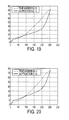
- a 200 Ipi clustered dot screen was used for the halftone. More specifically, FIG. 16 illustrates the True Hi-Addressability printer response versus the 0.5X 2x2 prediction: default state t1, and FIG. 17 the same at drifted state t2.
- FIG. 18 shows the True Hi-Addressability printer response versus the 1X 2x2 prediction at default state t1, and FIG. 19 the same at drifted state t2.
- FIGS. 20 and 21 respectively show the default (t1) and drifted (t2) states for True Hi-Addressability printer response versus the 2X 2x2 prediction, and FIG. 22 shows the True Hi-Addressability printer response versus the estimated response for drifted state t2.
- Equation 7 The salient features of the proposed correction in Equation 7 (Note: Eq. 7 is a generalization of Eq. 6, where only one resolution is used and the corresponding weight is equal to one) may be summarized as:
- These weights are in general optimized based on data from multiple printer states - however, this optimization needs to be carried out only once (offline) and once the weights are determined they may be used, as is, in real-time calibration paths. It is contemplated that such weights may be stored, for example, in a memory associated with color balance controller as represented by a printer ( FIG. 2 ; 90).
- a color correction method for a four-color printer is enumerated as follows. The method may be executed, for example, on the systems depicted in the embodiments of FIGS. 2A,B in accordance with preprogrammed instructions, or via other computing platforms associated with a printing system.
- the foregoing steps may also be characterized in a more general form, wherein the targets of the at least two resolution patches are printed with the halftone independent pattern and then measured to identify the printer response to the target. Separate measurement is accomplished by conventional means for spectral photometric devices.
- a halftone independent characterization of the device can then be modeled offline with a mathematical transformation comprising the measured response. "Offline" is intended to mean that the characterizing process is performed other than when the printer is performing a user/customer specified task in an ordinary work environment, whereas "online" is such a customer environment.
- a halftone screen dependent characterization is then modeled with the mathematical transformation to generate the predicted result. The predicted result is compared with a true color measured response to obtain a correction factor for the employed halftone screen print.
- a second halftone dependent characterization of the printer can then be modeled using the mathematical transformation and the correction factor.
Abstract
printing a target set of basic patches, for example using 2x2 spatial dot arrangements, said target set including patches having at least two resolutions and comprised of a fundamental binary pattern independent of a halftone screen;
measuring printer response from the target set;
modeling a halftone independent characterization of the printer with a mathematical transformation using the measured response;
modeling a first halftone dependent characterization of the printer with the mathematical transformation to generate a first predicted result using a halftone screen;
comparing a measured response of the printer using this halftone screen with the predicted result to define a correction factor corresponding to the halftone screen; and
modeling a second halftone dependent characterization of the printer using a predicted response of the fundamental binary pattern and the correction factor.
Description
- The present disclosure is directed to halftone independent temporal color drift correction, and more particularly to a system and method for such correction in hi-addressability xerographic printers.
- In today's business and scientific world, color is essential as a component of communication. Color facilitates the sharing of knowledge, and as a result companies involved in the development of digital color print engines are continuously seeking to improve the image quality of such products. One of the elements that affect image quality is the ability to consistently produce the same image quality on a printer over time. Colors on a printer tend to drift due to ink/toner variations, temperature fluctuations, type of media used, environment, etc. There has been a long felt commercial need for efficiently maintaining print color predictability, particularly as print media places greater importance on the accurate representation of merchandise in print and display media.
- Almost all color printers present some amount of temporal color drift, regardless of the nature of the print engine, etc. To maintain consistent color reproduction, it is generally necessary to monitor the printer performance and from time to time apply corresponding color adjustment to the printer. Although a full color characterization, for example as described by R. Bala, in "Device Characterization", Digital Color Imaging Handbook, Chapter 5 (CRC Press, ©2003), certainly can correct temporal color drift, some simpler color correction methods based on the 1-D tonal response curve (TRC) calibration for each individual channel usually are sufficient and are much easier to implement. The 1-D approach also readily lends itself to the use of in-line sensors for color measurement as described, for example in
U.S. Patent 6,744,531 to L. Mestha et al. Many different apparatus and methods have been proposed on this subject and most of them, like most color calibration and color characterization methods (see e.g., "Device Characterization" by R. Bala, supra), are halftone dependent. - The most popular technique to build a printer characterization transform involves printing and measuring a large set of color samples, i.e. CMY(K) patches, in conjunction with mathematical fitting and interpolation to derive CMY(K) -> Lab mappings. The accuracy of the characterization transform clearly depends on the number (N) of patches printed and measured. Crucially, note that these patches correspond to continuous tone CMY digital values, i.e. their binary representation is halftone dependent. Therefore, for color printers equipped with multiple halftone screens or halftone methods, the measurement and the correction has to be repeated as many times as the number of the halftones. For example, for a CMYK color printer equipped with five different halftone screens, monitoring the four channel TRCs needs a total of 4x5xN patches, where N is the number of chosen digital levels to print and to measure for each channel and each halftone screen. From practice it has been shown that the number of patches N for each halftone cannot be too small because the halftone TRC is usually not a smooth curve. The shape of a TRC depends not only on the design of the digital halftone screen, but also on the dot overlapping and other microscopic geometries of the physical output from the printer.
- For example,
FIG. 1 illustrates the measured TRCs for a 200 line per inch (Ipi) halftone screen. The solid and the dashed lines represent the results from printouts on two different paper substrates, respectively. It should be noted that neither TRC is very smooth; instead, they have a piecewise nature. If there are not enough levels printed and measured, an accurate estimate of the true TRC for the full range (i.e. digital level 0-255) cannot be derived even using sophisticated sampling and interpolation methods. It is not unusual, therefore, to find that even N = 16 patches (for each colorant channel) are not enough for a good TRC estimation. Thus, existing color correction methods when applied across multiple halftone screens likely prove to be time and measurement intensive and may not be desirable especially for an in-line correction. - In accordance with aspects of the disclosure temporal color drift of a printer can be corrected by a re-calibration of the color printer, quite often, by re-measuring and obtaining the tone response curves (TRCs) of the individual channels. For a printer equipped with multiple halftone screens or halftone methods, the color calibration process has to be repeated for each halftone selection. Furthermore, due to dot overlapping and other intrinsic microscopic structure, the native tone response of a halftone screen is seldom a smooth function. To get an accurate calibration of a halftone screen, the required number of patches to print, or the number of digital levels, cannot be too small. Therefore, it is believed beneficial to develop a halftone independent color drift correction method.
- A halftone independent color correction method was proposed by Shen-ge Wang, in
co-pending U.S. Application 11/343,656 US2007/0177231-A1 ), hereby incorporated by reference in its entirety, based on a 2x2 binary printer model for printers with isomorphic resolution up to 600 dpi. Another method was proposed by Shen-ge Wang, in co-pending U.S. Application [Attorney Docket 20070457-US-NP] for "HALFTONE INDEPENDENT DEVICE CHARACTERIZATION ACCOUNTING FOR COLORANT INTERACTIONS," filed , and also hereby incorporated by reference in its entirety. - Halftone independent color correction methods disclosed in above references are based on a 2x2 binary printer model for printers with isomorphic resolution up to 600 dpi. A fundamental assumption of the 2x2 printer model is that the rendered physical spot is no more than two logical image pixels wide. However, hi-addressability xerographic printers with printing resolutions much higher than 600 dpi violate this assumption. A halftone-independent color correction scheme was developed based on combining color predictions made using the 2x2 printer model for targets of varying resolution. Experiments conducted using two different 4800x600 hi-addressability printers confirm that the proposed color correction is very good and comparable to measurement and computation intensive halftone-dependent methods. Further benefits lie in the computational simplicity of the proposed scheme, and patch measurements that may be acquired by either a colorimetric device or a common desktop scanner.
- Disclosed in embodiments herein is a model-based, halftone independent method for characterizing a high-addressability printer equipped with a plurality of halftone screens, comprising: printing a target set of basic patches, said target set including patches having at least two resolutions and comprised of a fundamental binary pattern independent of a halftone screen; measuring printer response from the target set; modeling a halftone independent characterization of the printer with a mathematical transformation using the measured response; modeling a first halftone dependent characterization of the printer with the mathematical transformation to generate a first predicted result using a halftone screen; comparing a measured response of the printer using this halftone screen with the predicted result to define a correction factor corresponding to the halftone screen; and modeling a second halftone dependent characterization of the printer using a predicted response of the fundamental binary pattern and the correction factor.
- Further disclosed in embodiments herein is a halftone independent method for high-addressability device characterization comprising: calculating a binary printer model which is halftone independent; retrieving one of a set of user-selected halftones and a corresponding halftone correction factor; deriving a halftone correction factor as a mathematical transformation between a true color value as measured from the device, for at least two resolutions, and the predicted color value; processing a device color value using the selected halftone, the online binary printer model and a halftone correction factor to predict colorimetric values; and using the device color value and the predicted colorimetric values to produce an improved printer characterization for the user selected halftone.
- Also disclosed herein is a high-addressability printing system equipped with a plurality of halftone screens, comprising: memory storing at least one set of basic patches, said set including patches having at least two resolutions; a marking system for printing a target set of basic patches, said target set including patches having at least two resolutions and comprised of a fundamental binary pattern independent of a halftone screen; a colorimetric device, said device measuring printer response from the target set; and a color balance controller, said controller using the measured response and modeling a halftone independent characterization of the printer with a mathematical transformation to generate a first predicted result using a halftone screen, said color balance controller, further comparing a measured response of the printer using this halftone screen with the predicted result to define a correction factor corresponding to the halftone screen, and modeling a second halftone dependent characterization of the printer using a predicted response of the fundamental binary pattern and the correction factor.
-
FIG. 1 is a graphical illustration of exemplary measured TRCs for a halftone screen; -
FIG. 2 is an illustrative example of possible embodiment for the disclosed system for carrying out the methods disclosed herein; -
FIG. 3 is a representation of an idealized non-overlapping printer model; -
FIG. 4 is a representation of an exemplary circular-dot printer model; -
FIG. 5 is an exemplary representation of a Two-by-two printer model in accordance with an aspect of the disclosed method; -
FIGS. 6A - 6G illustrate seven 2x2 calibration patches representing seven "solid" gray levels; -
FIG. 7 illustrates seven 2x2 binary patterns defining seven "solid" levels for a single colorant printer (e.g., cyan) in accordance with the disclosed methods; -
FIGS. 8A - 8C are representative illustrations of "low-resolution" 2x2 patches for a typical 8X high addressability printer as described herein; and -
FIGS. 9 - 22 are graphical illustrations of various TRC curves for aspects of the disclosed embodiments. - The various embodiments described herein are not intended to limit the invention to those embodiments described. On the contrary, the intent is to cover all alternatives, modifications, and equivalents as may be included within the spirit and scope of the appended claims.
- As more particularly set forth below, the disclosed system and methods are directed to the calibration of high-adressability printing systems.
- In order to properly characterize the improved color correction, a 2x2 Printer Model is briefly reviewed. Previously, S. Wang and others, as noted above, proposed the halftone independent printer model, the 2x2 model, for calibrating black/white and color printers (see e.g.,
US Patents 5,469,267 ,5,748,330 ,5,854,882 ,6,266,157 ,6,435,654 , and S. Wang, "Two-by-two centering printer model with Yule-Nielsen Equation", Proc. IS&T NIP14, 1998, all of which are hereby incorporated by reference in their entirety). For the current disclosure, the 2x2 concept for the black/white, or monochromatic, applications is briefly characterized. - Few hard-copy devices generate square-shape non-overlapping
output pixels 100 as shown inFIG. 3 ; representing an idealized non-overlapping printer model. Instead, overlapping between adjacent spots is not only common but quite significant from most printers. The combination of geometric overlapping and optical scattering in the paper or substrate creates many difficulties even in modeling a simple black/white printer. The most common printer model considering dot overlapping (e.g., 110) is the circular-dot printer model, illustrated for example inFIG. 4 . - The difference between the 2x2 printer model, shown by
FIG. 5 , and the conventional approach, shown byFIG. 4 , is the definition of the output pixels. InFIG. 5 , each output pixel, represented by arectangle 100, is centered coincident with the circular spot, representing the physical output by the printer. Obviously, the grid defining the output pixels is a conceptual coordinate for modeling purpose only. Any change on the grid, or the coordinate, will not affect the actual physical output of the printer at all. Therefore, it is possible to shift the grid to the position shown inFIG. 5 , so that eachspot 200, representing the physical output, is centered at one cross point of the grid 210. - Although the dot pattern in
FIG. 5 is exactly the same one inFIG. 4 , overlapping details within output pixels defined by the new grid inFIG. 5 are completely different from output pixels defined by a conventional coordinate, shown inFIG. 4 . It is not difficult to prove that there are only 24=16 different overlapping patterns in the 2x2 printer model, instead of 29=512 different overlapping patterns in the conventional circular-dot model. The 16 different overlapping patterns can be further grouped into seven categories, G0 to G6, as represented by the seven patches shown inFIGS. 6A-6G . The patches G0 and G6 are solid white and solid black, respectively. The patch G1 is one of four different overlapping patterns, which are mirror images to each other. Similarly, patch G5 is also formed of four overlapping patterns. Each of the patches G2, G3 and G4 are one of two different overlapping patterns, which are also mirror images to each other. Therefore, in terms of the "ink" coverage, or the gray level, all pixels of each of the seven patches are identical. In other words, each patch only consists of one gray level at the pixel level, just like the solid white or black, and this gray level can be measured as exactly as any solid color. - The ideal binary representations of the seven 2x2 patches (T0 - T6) are shown in
FIG. 7 . Once the seven 2x2 patches are printed and the corresponding seven "solid" gray levels are measured, the 2x2 printer model can be used to predict the gray output of any binary pattern. For example, the output of the binary pattern inFIG. 3 can be illustrated byFIG. 5 using the 2x2 printer model and described by Table 1, where G0-G6 are the measured gray levels from one of the corresponding seven 2x2 patches T0-T6, respectively (i.e., binary output illustrated inFIG. 3 represented as one of seven 2x2 patterns for each cell in the table).Table 1 G1 G2 G1 G1 G1 G1 G1 G1 G2 G1 G1 G1 G1 G1 G0 G1 G2 G2 G1 G0 G0 G0 G3 G5 G2 G4 G1 G0 G1 G5 G3 G0 G1 G4 G1 G2 G6 G5 G1 G1 G4 G1 G1 G2 G2 G1 G1 G1 G0 - To estimate the average gray output of any binary pattern, the 2x2 printer model uses the Neugebauer equation with the Yule-Nielson modification as follows:

where Gi , i = 0 to 6, is the measured gray level of each of the seven 2x2 patches, ni is the number of pixels of the corresponding 2x2 patch in the given binary pattern, and γ is the Yule-Nielsen factor, which is often chosen as a fitting parameter. As a further example, the average gray level of the binary pattern shown inFIG. 2 can be estimated as
- The color 2x2 printer model can be described in a similar manner and can be found in the references noted previously. The 2x2 printer model can predict the color appearance of any binary patterns for a given color printer and the color accuracy of the prediction by the 2x2 model is very high for printers with relatively uniform spot shapes, for example inkjet printers.
- Color correction or calibration algorithms typically use the response of a printer along each (e.g. C,M,Y,K) of its colorant channels. In such cases, the monochrome 2x2 model can successfully be employed for predicting color response of the printer along the individual colorant channels. Xerographic printers however, usually do not generate uniform round-shape spots for isolated single pixels and the dot overlapping is more complicated than inkjet outputs. The 2x2 printer model applied to a xerographic printer may yield larger prediction errors. However, modeling of these systematic errors leads to aspects of the disclosed color correction scheme. For example, in previous work on temporal drift correction (e.g., co-pending 11/343,656 by S. Wang et al., for "Halftone Independent Color Drift Correction") for printers with isomorphic resolution up to 600 dpi, a core underlying principle was identified. The basic premise was that, over time, for each colorant and halftoning algorithm, the 2x2 predicted response deviates from the true printer response in an invariant manner.
- Mathematically, this may be described as:

where Rtrue(t,i,H) = true/measured response of ith colorant at time t, R2x2(t,i, H) = 2x2 predicted response of ith colorant at time t and H represents the halftoning method used, i = C, M, Y, K - In particular, this invariant relationship may be given as

where Rtrue(t,i,H) = true/measured response of ith colorant at time t in deltaE from paper;
R2x2(t,i,H) = 2x2 predicted response of ith colorant at time t in deltaE from paper; and
H represents the halftoning method used, i= C, M, Y, K.
The illustrated relationship states that, given the knowledge of the 2x2 and true/measured printer response at a default or reference printer state t1, it is possible to estimate the true response at a drifted state t2 as:
- Alternatively, the above may be rewritten as:

- Referring to
FIG. 2 , it can be seen that a particular printer device can be characterized with a reduced number of CMY test target color values 80 for a particular halftone screen pattern 82 by using the disclosed model determined offline with the fundamental binary pattern that is halftone independent 84, 86 and a correction factor (e.g., sum of weighting factors of at least two resolutions) that has been previously derived offline and then stored for correspondence to the selected halftone screen 82. The true color values of the printing device are measured 90 and in error metric calculation, ΔEab 92 is calculated for use in the transform for characterizing printing system operation. Printing, as represented in 90, may be carried out by a marking system for printing a target set of patches, including patches having at least two resolutions and comprised of a fundamental binary pattern independent of a halftone screen. Measurement as referenced in 90 may be completed by a colorimetric device, the device measuring printer response from the target set, wherein a color balance controller uses the measured response and modeling a halftone independent characterization of the printer with a mathematical transformation. - Based upon pre-computed and stored knowledge of the true printer response and the 2x2 printer response at a reference printer state t1, an estimate of the true printer response at a drifted printer state t2 could be accurately determined by printing and measuring only the halftone independent 2x2 patches (7 for each colorant and 25 for a 4 color printer; discounting the repeated measurements of the white patch). The crucial assumption in the equation above is that the functional mapping from the 2x2 predicted response does not depend on time. Physically, such a modeling is motivated by the fact that the difference between the 2x2 printer model and the true measured response is attributed to the geometric assumptions made by the model. It is reasonable then to assume that the differences in the dot overlap geometry assumed by 2x2 versus the true dot overlap geometry should, on average, be the same irrespective of time, i.e. in particular the relationship between the 2x2 and true response should be mathematically invariant across time. This assumption was experimentally verified in previous work S. Wang, et al. as noted previously.
- However, a meaningful color response prediction is difficult to obtain via the 2x2 printer model for hi-addressability xerographic printers, particularly with resolutions much greater than 600 dpi, because a premise fundamental to the 2x2 printer model is that the rendered physical spot should not be more than two digital pixels wide. This premise is violated for hi-addressability printers. In view of this difficulty, the relationship between a "low-resolution" 2x2 prediction and the true hires response of the printer along each of the colorant channels cyan, magenta, yellow and black (C, M, Y, K, respectively) was investigated. As a result, it was determined that a similar invariance could hold, but that 2x2 predictions from several different, lower resolutions needed to be combined. The current disclosure is, therefore, directed to a new halftone-independent color correction for hi-addressability xerographic printers.
-
FIGS. 8A - 8C show, respectively, "low-resolution" 2x2 patches for a typical 8X high addressability printer used in experiments (e.g., where resolution in one direction is eight times the resolution in the perpendicular direction) - respectively illustrating a cyan channel at resolutions of 600, 1200 and 2400 x 600. As is apparent fromFIGS. 8A-C , it is possible to obtain low-resolution 2x2 predictions by pixel replication of the 2x2 binary patterns in the digital file, and subsequently obtain macroscopic measurements of the printed patch. As an example, for an 8X hi-addressability printer of resolution 4800 x 600 a "low-resolution 1X" 2x2 prediction is obtained by printing and measuring 2x2 patches at 600 x 600 with pixel replication by a factor of eight in the appropriate direction. Because assumptions of the 2x2 printer model hold approximately true at these lower-resolutions, a goal was to explore if there is a stable pattern to the way the low-resolution 2x2 predictions deviate from the true hi-addressability response. It was observed that an invariance similar to the one developed before holds, but that 2x2 predictions from several different lower resolutions need to be combined. - In particular, it was determined that an estimate of the true hi-resolution printer response at time t2 is given by:

where i, H are as before and j denotes the resolution of the 2x2 prediction; as an example for an 8X hi-addressability printer j = 1X, 2X, 4X etc. -
FIGS. 9 and10 , respectively, plot the 2x2 predicted response (solid) and the true printer response (dashed) for the Magenta channel at default (t1) and drifted (t2) printer states. A 175 Ipi clustered dot halftone screen was employed. Both responses are in deltaE (ΔE) from paper and for a 4800 x 600 (i.e. 8X hi-addressability), for example a xerographic printer. The 2x2 prediction inFIGS. 9 and10 is obtained by printing and measuring the 2x2 patches at 1X resolution (i.e. 600 x 600 binary and scaled by a factor of 8). Similar plots forresolutions FIGS. 11-12 andFIGS. 13-14 , respectively. - Referring next to
FIG. 15 , depicted therein is the estimated (solid line) 2x2 response from using Equation 7 versus the true measured hi-addressability (dashed line) response. As is evident fromFIG. 15 , there is a near perfect overlap between the true (dashed) and estimated (solid) responses. - Similar plots and the corresponding correction for the Cyan channel of another xerographic hi-addressability printer are shown in
FIGS. 16 through 22 . A 200 Ipi clustered dot screen was used for the halftone. More specifically,FIG. 16 illustrates the True Hi-Addressability printer response versus the 0.5X 2x2 prediction: default state t1, andFIG. 17 the same at drifted state t2.FIG. 18 shows the True Hi-Addressability printer response versus the 1X 2x2 prediction at default state t1, andFIG. 19 the same at drifted state t2.FIGS. 20 and21 respectively show the default (t1) and drifted (t2) states for True Hi-Addressability printer response versus the 2X 2x2 prediction, andFIG. 22 shows the True Hi-Addressability printer response versus the estimated response for drifted state t2. - The salient features of the proposed correction in Equation 7 (Note: Eq. 7 is a generalization of Eq. 6, where only one resolution is used and the corresponding weight is equal to one) may be summarized as:
- A) The strongest weight was attached to the lowest resolution. In particular, the lowest resolution is the most robust (i.e. insensitive to measurement noise, etc.) but provides a coarse approximation; while the higher resolutions better capture the detail. This can be observed easily in
FIGS. 16 through 22 . - B) the experiments used weights w1 = 0.45; w2 = 0.3; w3 = 0.25 for a first test printer; and w1 = 0.48, w2 = 0.29, w3 = 0.23 for a second test printer. These weights are in general optimized based on data from multiple printer states - however, this optimization needs to be carried out only once (offline) and once the weights are determined they may be used, as is, in real-time calibration paths. It is contemplated that such weights may be stored, for example, in a memory associated with color balance controller as represented by a printer (
FIG. 2 ; 90). - In light of the disclosure above, a color correction method for a four-color printer is enumerated as follows. The method may be executed, for example, on the systems depicted in the embodiments of
FIGS. 2A,B in accordance with preprogrammed instructions, or via other computing platforms associated with a printing system. - I. At a time t1 (default or reference printer state), and
For each colorant channel:- A. Print and measure a plurality (e.g., seven) 2x2 patches shown in
FIG. 7 at the required number of resolutions (at least two); - B. For each halftone screen or method:
- 1. To get a 2x2 TRC estimation, for each constant input digital level:
- a. Derive the output binary pattern;
- b. Use the 2x2 printer model to interpret the binary pattern as a seven-level gray image;
- c. Use Eq. 1, and the measurement of seven 2x2 patches, to get the average output;
- 2. Store the 2x2 TRC predictions at t1 and for each resolution into the memory;
- 3. Obtain the true TRC by printing and measuring the outputs of different levels and store the true TRC into the memory.
- 1. To get a 2x2 TRC estimation, for each constant input digital level:
- A. Print and measure a plurality (e.g., seven) 2x2 patches shown in
- II. Later, at a time t2 (drifted printer state), and
For each colorant channel:- A. Print and measure the seven 2x2 patches shown by
FIG. 7 at the required number of resolutions; - B. For each halftone screen or method:
- 1. To get a 2x2 TRC estimation, for each constant input level:
- a. Derive the output binary pattern;
- b. Use the 2x2 printer model to interpret the binary pattern as a seven-level gray image;
- c. Use Eq. 1, and the measured result from the step 2a to get the average output;
- 2. Calculate the correction factor (e.g., sum of weighting factors of at least two resolutions) as in the large square brackets in Eq. 7 (for each digital level) by using the 2x2 TRC estimation at t2 and the 2x2 estimation stored at the initial time t1;
- 3. Apply the correction obtained above to the true TRC stored at t1 (1.3.) to predict the true TRC at the new time t2
- 4. Make a corresponding adjustment to the input image based on the predicted true TRC for correcting the color drift.
- 1. To get a 2x2 TRC estimation, for each constant input level:
- A. Print and measure the seven 2x2 patches shown by
- The foregoing steps may also be characterized in a more general form, wherein the targets of the at least two resolution patches are printed with the halftone independent pattern and then measured to identify the printer response to the target. Separate measurement is accomplished by conventional means for spectral photometric devices. A halftone independent characterization of the device can then be modeled offline with a mathematical transformation comprising the measured response. "Offline" is intended to mean that the characterizing process is performed other than when the printer is performing a user/customer specified task in an ordinary work environment, whereas "online" is such a customer environment. A halftone screen dependent characterization is then modeled with the mathematical transformation to generate the predicted result. The predicted result is compared with a true color measured response to obtain a correction factor for the employed halftone screen print. A second halftone dependent characterization of the printer can then be modeled using the mathematical transformation and the correction factor.
Claims (15)
- A model-based, halftone independent method for characterizing a high-addressability printer equipped with a plurality of halftone screens, comprising:printing a target set of basic patches, for example using 2x2 spatial dot arrangements, said target set including patches having at least two resolutions and comprised of a fundamental binary pattern independent of a halftone screen;measuring printer response from the target set;modeling a halftone independent characterization of the printer with a mathematical transformation using the measured response;modeling a first halftone dependent characterization of the printer with the mathematical transformation to generate a first predicted result using a halftone screen;comparing a measured response of the printer using this halftone screen with the predicted result to define a correction factor corresponding to the halftone screen; andmodeling a second halftone dependent characterization of the printer using a predicted response of the fundamental binary pattern and the correction factor.
- The method of claim 1, wherein the modeling of the halftone independent characterization is temporally invariant.
- A halftone independent method for high-addressability device characterization comprising:calculating a binary printer model which is halftone independent;retrieving one of a set of user-selected halftones and a corresponding halftone correction factor;deriving a halftone correction factor as a mathematical transformation between a true color value as measured from the device, for at least two resolutions, and the predicted color value;processing a device color value using the selected halftone, the online binary printer model and a halftone correction factor to predict colorimetric values; andusing the device color value and the predicted colorimetric values to produce an improved printer characterization for the user selected halftone.
- The method of any of the preceding claims, wherein the printer model is a, typically halftone independent characterization, binary printer model parameterized by a table of values generated by printing and measuring canonical binary patterns which are halftone independent.
- The method of any of the preceding claims, wherein the correction factor can be expressed as a sum of weighting factors of at least two resolutions.
- The method of any of the preceding claims, wherein said model comprises at least a first weighting factor and a second weighting factor, wherein the first weighting factor is greater than the second weighting factor and is applied to measure color for the lower of the at least two resolutions.
- The method of any of the preceding claims, wherein said test target set includes at least about seven test patch patterns for each resolution.
- The method of any of the preceding claims, wherein the high-adressability printer operates at an 8X addressability.
- A high-addressability printing system equipped with a plurality of halftone screens, comprising:memory storing at least one set of basic patches, said set including patches having at least two resolutions;a marking system for printing a target set of basic patches, said target set including patches having at least two resolutions and comprised of a fundamental binary pattern independent of a halftone screen;a colorimetric device, said device measuring printer response from the target set; anda color balance controller, said controller using the measured response and modeling a halftone independent characterization of the printer with a mathematical transformation to generate a first predicted result using a halftone screen, said color balance controller, further comparing a measured response of the printer using this halftone screen with the predicted result to define a correction factor corresponding to the halftone screen, and modeling a second halftone dependent characterization of the printer using a predicted response of the fundamental binary pattern and the correction factor.
- The high-addressability printing system of claim 9, wherein said memory stores a target set including patches printed using 2x2 spatial dot arrangements.
- The high-addressability printing system of claim 9 or claim 10, wherein a temporally invariant model is employed by the color balance controller.
- The high-addressability printing system of claim 11, wherein the printer model is a halftone independent characterization binary printer model parameterized by a table of values generated by printing and measuring binary patterns which are halftone independent.
- The high-addressability printing system of any of claims 9 to 12, wherein the correction factor is stored in memory for use by the controller, and can be expressed as a sum of weighting factors of at least two resolutions.
- The high-addressability printing system of any of claims 9 to 13, wherein said model comprises at least a first weighting factor and a second weighting factor, wherein the first weighting factor is greater than the second weighting factor and is applied to measure color for the lower of the at least two resolutions.
- The high-addressability printing system of any of claims 9 to 14, wherein said test target set stored in said memory includes at least about seven test patch patterns for each of said resolutions.
Applications Claiming Priority (1)
| Application Number | Priority Date | Filing Date | Title |
|---|---|---|---|
| US12/355,450 US8274706B2 (en) | 2009-01-16 | 2009-01-16 | System and method for halftone independent temporal color drift correction in hi-addressability xerographic printers |
Publications (2)
| Publication Number | Publication Date |
|---|---|
| EP2209297A1 true EP2209297A1 (en) | 2010-07-21 |
| EP2209297B1 EP2209297B1 (en) | 2017-03-15 |
Family
ID=42072836
Family Applications (1)
| Application Number | Title | Priority Date | Filing Date |
|---|---|---|---|
| EP10150479.3A Not-in-force EP2209297B1 (en) | 2009-01-16 | 2010-01-12 | System and method for halftone independent temporal color drift correction in hi-addressability xerographic printers |
Country Status (3)
| Country | Link |
|---|---|
| US (1) | US8274706B2 (en) |
| EP (1) | EP2209297B1 (en) |
| JP (1) | JP2010166563A (en) |
Families Citing this family (6)
| Publication number | Priority date | Publication date | Assignee | Title |
|---|---|---|---|---|
| US8477374B2 (en) * | 2010-09-30 | 2013-07-02 | Xerox Corporation | Cost-effective binary printer models for multi-color printers by improved reflectance modeling and patch clustering |
| US8437040B2 (en) * | 2010-10-07 | 2013-05-07 | Xerox Corporation | Method and system for digitally controlling image printing system to achieve desired color density of printed image |
| US8824005B2 (en) * | 2011-06-21 | 2014-09-02 | Eastman Kodak Company | Method of designing a color chart |
| JP6107164B2 (en) * | 2012-02-15 | 2017-04-05 | 株式会社リコー | Color measuring device, image forming apparatus, color measuring method and color measuring system |
| JP5990093B2 (en) * | 2012-11-29 | 2016-09-07 | キヤノン株式会社 | Image processing apparatus, image processing method, and program |
| US9876943B2 (en) | 2014-08-12 | 2018-01-23 | Xerox Corporation | Color managed printing system |
Citations (12)
| Publication number | Priority date | Publication date | Assignee | Title |
|---|---|---|---|---|
| US5469267A (en) | 1994-04-08 | 1995-11-21 | The University Of Rochester | Halftone correction system |
| US5748330A (en) | 1997-05-05 | 1998-05-05 | Xerox Corporation | Method of calibrating a digital printer using component test patches and the yule-nielsen equation |
| US5854882A (en) | 1994-04-08 | 1998-12-29 | The University Of Rochester | Halftone correction systems |
| US5943477A (en) * | 1998-05-26 | 1999-08-24 | International Business Machines Corporation | Microlocal calibration of digital printers |
| US6266157B1 (en) | 1998-11-13 | 2001-07-24 | Xerox Corporation | Method of error diffusion using 2×2 color correction and increment matching |
| WO2001091453A1 (en) * | 2000-05-22 | 2001-11-29 | Mark Priest | Calibrating printing machines |
| US6435654B1 (en) | 1999-11-29 | 2002-08-20 | Xerox Corporation | Color calibration for digital halftoning |
| US6606167B1 (en) * | 1999-06-01 | 2003-08-12 | Adobe Systems Incorporated | Calibrating a printer using a self-printed chart |
| EP1365576A2 (en) * | 2002-05-22 | 2003-11-26 | Creo IL. Ltd. | Dot gain calibration method and apparatus |
| US6744531B1 (en) | 1998-12-29 | 2004-06-01 | Xerox Corporation | Color adjustment apparatus and method |
| US20070177231A1 (en) | 2006-01-31 | 2007-08-02 | Xerox Corporation | Halftone independent color drift correction |
| WO2008133629A1 (en) * | 2007-04-30 | 2008-11-06 | Hewlett-Packard Development Company, L.P. | Halftone printing with different screens |
Family Cites Families (22)
| Publication number | Priority date | Publication date | Assignee | Title |
|---|---|---|---|---|
| US5107332A (en) | 1989-05-17 | 1992-04-21 | Hewlett-Packard Company | Method and system for providing closed loop color control between a scanned color image and the output of a color printer |
| EP0720351B1 (en) * | 1994-12-28 | 2003-04-02 | Fuji Photo Film Co., Ltd. | Method for producing color proof |
| US5749020A (en) * | 1996-11-21 | 1998-05-05 | Xerox Corporation | Coordinitization of tone reproduction curve in terms of basis functions |
| US6697167B1 (en) * | 1997-08-29 | 2004-02-24 | Canon Kabushiki Kaisha | Image processing apparatus and method |
| US6804025B1 (en) * | 1999-03-24 | 2004-10-12 | Brother Kogyo Kabushiki Kaisha | Calibration data preparing system |
| US7307752B1 (en) * | 2000-05-05 | 2007-12-11 | Xerox Corporation | On-line calibration system for a dynamically varying color marking device |
| US6775029B1 (en) * | 2000-10-30 | 2004-08-10 | Xerox Corporation | Method for efficient calibration of printing devices |
| US6999199B2 (en) * | 2000-12-28 | 2006-02-14 | Xerox Corporation | Method and system of individualizing tone-reproduction curves calibration and applying thereof |
| US7206099B2 (en) * | 2002-07-16 | 2007-04-17 | Xerox Corporation | Media/screen look-up-table for color consistency |
| US6851785B2 (en) * | 2002-09-10 | 2005-02-08 | Hewlett-Packard Development Company, L.P. | Calibration method and apparatus using interpolation |
| US6694109B1 (en) * | 2003-01-15 | 2004-02-17 | Xerox Corporation | Real-time control of tone reproduction curve by redefinition of lookup tables from fit of in-line enhanced toner area coverage (ETAC) data |
| US20040150858A1 (en) * | 2003-01-31 | 2004-08-05 | Cholewo Tomasz J. | Method, apparatus and system for image data correction |
| US7423778B2 (en) * | 2003-08-01 | 2008-09-09 | Ecole Polytechnique Federale De Lausanne (Epfl) | Prediction model for color separation, calibration and control of printers |
| US7570402B2 (en) * | 2003-10-31 | 2009-08-04 | Seiko Epson Corporation | Printing method and printing system |
| US7419238B2 (en) * | 2004-02-10 | 2008-09-02 | Seiko Epson Corporation | Printing method, printing apparatus, printing system, and printed medium |
| US7593132B2 (en) * | 2004-09-30 | 2009-09-22 | Lexmark International, Inc. | Method for calibrating printing of lenticular images to lenticular media |
| US7440139B2 (en) * | 2005-01-13 | 2008-10-21 | Xerox Corporation | Systems and methods for controlling a tone reproduction curve using error diffusion |
| US7715069B2 (en) * | 2005-04-28 | 2010-05-11 | Seiko Epson Corporation | Method for measuring density, printing method, method of calculating correction value, method of manufacturing printing apparatus and method for obtaining correction value |
| JP4770258B2 (en) * | 2005-04-28 | 2011-09-14 | セイコーエプソン株式会社 | Correction value setting method and correction value setting device |
| US7710609B2 (en) * | 2005-05-24 | 2010-05-04 | Xerox Corporation | Page edge correction systems and methods |
| JP4356720B2 (en) * | 2006-08-29 | 2009-11-04 | セイコーエプソン株式会社 | Printing method and printing apparatus |
| EP1970770B1 (en) * | 2007-03-15 | 2013-09-18 | Konica Minolta Business Technologies, Inc. | Image forming apparatus with means to calibrate a toner density sensor |
-
2009
- 2009-01-16 US US12/355,450 patent/US8274706B2/en active Active
-
2010
- 2010-01-12 JP JP2010003788A patent/JP2010166563A/en not_active Withdrawn
- 2010-01-12 EP EP10150479.3A patent/EP2209297B1/en not_active Not-in-force
Patent Citations (12)
| Publication number | Priority date | Publication date | Assignee | Title |
|---|---|---|---|---|
| US5469267A (en) | 1994-04-08 | 1995-11-21 | The University Of Rochester | Halftone correction system |
| US5854882A (en) | 1994-04-08 | 1998-12-29 | The University Of Rochester | Halftone correction systems |
| US5748330A (en) | 1997-05-05 | 1998-05-05 | Xerox Corporation | Method of calibrating a digital printer using component test patches and the yule-nielsen equation |
| US5943477A (en) * | 1998-05-26 | 1999-08-24 | International Business Machines Corporation | Microlocal calibration of digital printers |
| US6266157B1 (en) | 1998-11-13 | 2001-07-24 | Xerox Corporation | Method of error diffusion using 2×2 color correction and increment matching |
| US6744531B1 (en) | 1998-12-29 | 2004-06-01 | Xerox Corporation | Color adjustment apparatus and method |
| US6606167B1 (en) * | 1999-06-01 | 2003-08-12 | Adobe Systems Incorporated | Calibrating a printer using a self-printed chart |
| US6435654B1 (en) | 1999-11-29 | 2002-08-20 | Xerox Corporation | Color calibration for digital halftoning |
| WO2001091453A1 (en) * | 2000-05-22 | 2001-11-29 | Mark Priest | Calibrating printing machines |
| EP1365576A2 (en) * | 2002-05-22 | 2003-11-26 | Creo IL. Ltd. | Dot gain calibration method and apparatus |
| US20070177231A1 (en) | 2006-01-31 | 2007-08-02 | Xerox Corporation | Halftone independent color drift correction |
| WO2008133629A1 (en) * | 2007-04-30 | 2008-11-06 | Hewlett-Packard Development Company, L.P. | Halftone printing with different screens |
Non-Patent Citations (3)
| Title |
|---|
| ALLEBACH J P ET AL: "Model-based digital halftoning", IEEE SIGNAL PROCESSING MAGAZINE, IEEE SERVICE CENTER, PISCATAWAY, NJ, US LNKD- DOI:10.1109/MSP.2003.1215227, vol. 20, no. 4, 1 July 2003 (2003-07-01), pages 14 - 27, XP011098942, ISSN: 1053-5888 * |
| HERSCH R.D.: "Improving the Yule-Nielsen modified spectral Neugebauer model by dot surface coverages depending on the ink superposition conditions", PROCEEDINGS OF THE SPIE, vol. 5667, no. 1, 17 January 2005 (2005-01-17), San Jose , USA, pages 434 - 447, XP002578207 * |
| S. WANG: "Two-by-two centering printer model with Yule-Nielsen Equation", PROC. IS&T NIP14, 1998 |
Also Published As
| Publication number | Publication date |
|---|---|
| US8274706B2 (en) | 2012-09-25 |
| JP2010166563A (en) | 2010-07-29 |
| US20100182616A1 (en) | 2010-07-22 |
| EP2209297B1 (en) | 2017-03-15 |
Similar Documents
| Publication | Publication Date | Title |
|---|---|---|
| US5649073A (en) | Automatic calibration of halftones | |
| EP1814303B1 (en) | Halftone independent color drift correction | |
| US7295703B2 (en) | Method for scanner characterization for color measurement of printed media having four or more colorants | |
| US8339674B2 (en) | Halftone independent correction of spatial non-uniformities | |
| US8023156B2 (en) | Image output color management system and method | |
| CN101072291B (en) | Color processing apparatus and method thereof | |
| US8305660B2 (en) | Methods and systems achieving print uniformity using reduced memory or computational requirements | |
| US8270049B2 (en) | System and method for high resolution characterization of spatial variance of color separation misregistration | |
| EP2209297B1 (en) | System and method for halftone independent temporal color drift correction in hi-addressability xerographic printers | |
| JP4898342B2 (en) | Color conversion method and color conversion system | |
| EP1729257A2 (en) | Inter-separation decorrelator | |
| US20100208304A1 (en) | Image correction method and image correction system | |
| JP2007049711A (en) | Color transformation method and color transformation system | |
| US8314978B2 (en) | Halftone independent device characterization accounting for colorant interactions | |
| US6266157B1 (en) | Method of error diffusion using 2×2 color correction and increment matching | |
| US7639410B2 (en) | Optimal test patch selection for multi-media printing systems using low rank approximation | |
| EP1596576A2 (en) | Method for closed loop characterization | |
| EP2296364B1 (en) | Methods and system for improved color characterization | |
| Lee et al. | Scanner characterization for color measurement and diagnostics | |
| Bugnon et al. | Recovering neugebauer colorant reflectances and Ink‐spreading curves from printed color images | |
| US8462389B2 (en) | Halftone-independent scanner profiling | |
| Monga et al. | Halftone independent methods for color drift correction | |
| Monga et al. | Channel-separable halftone independent methods for color drift correction | |
| Stanek et al. | Scanning parameter selection for inkjet print analysis | |
| JP4548261B2 (en) | Color prediction method, color prediction apparatus, and color prediction program |
Legal Events
| Date | Code | Title | Description |
|---|---|---|---|
| PUAI | Public reference made under article 153(3) epc to a published international application that has entered the european phase |
Free format text: ORIGINAL CODE: 0009012 |
|
| AK | Designated contracting states |
Kind code of ref document: A1 Designated state(s): AT BE BG CH CY CZ DE DK EE ES FI FR GB GR HR HU IE IS IT LI LT LU LV MC MK MT NL NO PL PT RO SE SI SK SM TR |
|
| 17P | Request for examination filed |
Effective date: 20110121 |
|
| GRAP | Despatch of communication of intention to grant a patent |
Free format text: ORIGINAL CODE: EPIDOSNIGR1 |
|
| INTG | Intention to grant announced |
Effective date: 20160926 |
|
| GRAS | Grant fee paid |
Free format text: ORIGINAL CODE: EPIDOSNIGR3 |
|
| GRAA | (expected) grant |
Free format text: ORIGINAL CODE: 0009210 |
|
| AK | Designated contracting states |
Kind code of ref document: B1 Designated state(s): AT BE BG CH CY CZ DE DK EE ES FI FR GB GR HR HU IE IS IT LI LT LU LV MC MK MT NL NO PL PT RO SE SI SK SM TR |
|
| REG | Reference to a national code |
Ref country code: CH Ref legal event code: EP Ref country code: GB Ref legal event code: FG4D |
|
| REG | Reference to a national code |
Ref country code: IE Ref legal event code: FG4D |
|
| REG | Reference to a national code |
Ref country code: AT Ref legal event code: REF Ref document number: 876640 Country of ref document: AT Kind code of ref document: T Effective date: 20170415 |
|
| REG | Reference to a national code |
Ref country code: DE Ref legal event code: R096 Ref document number: 602010040701 Country of ref document: DE |
|
| REG | Reference to a national code |
Ref country code: NL Ref legal event code: MP Effective date: 20170315 |
|
| REG | Reference to a national code |
Ref country code: LT Ref legal event code: MG4D |
|
| PG25 | Lapsed in a contracting state [announced via postgrant information from national office to epo] |
Ref country code: FI Free format text: LAPSE BECAUSE OF FAILURE TO SUBMIT A TRANSLATION OF THE DESCRIPTION OR TO PAY THE FEE WITHIN THE PRESCRIBED TIME-LIMIT Effective date: 20170315 Ref country code: NO Free format text: LAPSE BECAUSE OF FAILURE TO SUBMIT A TRANSLATION OF THE DESCRIPTION OR TO PAY THE FEE WITHIN THE PRESCRIBED TIME-LIMIT Effective date: 20170615 Ref country code: GR Free format text: LAPSE BECAUSE OF FAILURE TO SUBMIT A TRANSLATION OF THE DESCRIPTION OR TO PAY THE FEE WITHIN THE PRESCRIBED TIME-LIMIT Effective date: 20170616 Ref country code: LT Free format text: LAPSE BECAUSE OF FAILURE TO SUBMIT A TRANSLATION OF THE DESCRIPTION OR TO PAY THE FEE WITHIN THE PRESCRIBED TIME-LIMIT Effective date: 20170315 Ref country code: HR Free format text: LAPSE BECAUSE OF FAILURE TO SUBMIT A TRANSLATION OF THE DESCRIPTION OR TO PAY THE FEE WITHIN THE PRESCRIBED TIME-LIMIT Effective date: 20170315 |
|
| REG | Reference to a national code |
Ref country code: AT Ref legal event code: MK05 Ref document number: 876640 Country of ref document: AT Kind code of ref document: T Effective date: 20170315 |
|
| PG25 | Lapsed in a contracting state [announced via postgrant information from national office to epo] |
Ref country code: SE Free format text: LAPSE BECAUSE OF FAILURE TO SUBMIT A TRANSLATION OF THE DESCRIPTION OR TO PAY THE FEE WITHIN THE PRESCRIBED TIME-LIMIT Effective date: 20170315 Ref country code: LV Free format text: LAPSE BECAUSE OF FAILURE TO SUBMIT A TRANSLATION OF THE DESCRIPTION OR TO PAY THE FEE WITHIN THE PRESCRIBED TIME-LIMIT Effective date: 20170315 Ref country code: BG Free format text: LAPSE BECAUSE OF FAILURE TO SUBMIT A TRANSLATION OF THE DESCRIPTION OR TO PAY THE FEE WITHIN THE PRESCRIBED TIME-LIMIT Effective date: 20170615 |
|
| PG25 | Lapsed in a contracting state [announced via postgrant information from national office to epo] |
Ref country code: NL Free format text: LAPSE BECAUSE OF FAILURE TO SUBMIT A TRANSLATION OF THE DESCRIPTION OR TO PAY THE FEE WITHIN THE PRESCRIBED TIME-LIMIT Effective date: 20170315 |
|
| PG25 | Lapsed in a contracting state [announced via postgrant information from national office to epo] |
Ref country code: CZ Free format text: LAPSE BECAUSE OF FAILURE TO SUBMIT A TRANSLATION OF THE DESCRIPTION OR TO PAY THE FEE WITHIN THE PRESCRIBED TIME-LIMIT Effective date: 20170315 Ref country code: EE Free format text: LAPSE BECAUSE OF FAILURE TO SUBMIT A TRANSLATION OF THE DESCRIPTION OR TO PAY THE FEE WITHIN THE PRESCRIBED TIME-LIMIT Effective date: 20170315 Ref country code: AT Free format text: LAPSE BECAUSE OF FAILURE TO SUBMIT A TRANSLATION OF THE DESCRIPTION OR TO PAY THE FEE WITHIN THE PRESCRIBED TIME-LIMIT Effective date: 20170315 Ref country code: ES Free format text: LAPSE BECAUSE OF FAILURE TO SUBMIT A TRANSLATION OF THE DESCRIPTION OR TO PAY THE FEE WITHIN THE PRESCRIBED TIME-LIMIT Effective date: 20170315 Ref country code: RO Free format text: LAPSE BECAUSE OF FAILURE TO SUBMIT A TRANSLATION OF THE DESCRIPTION OR TO PAY THE FEE WITHIN THE PRESCRIBED TIME-LIMIT Effective date: 20170315 Ref country code: SK Free format text: LAPSE BECAUSE OF FAILURE TO SUBMIT A TRANSLATION OF THE DESCRIPTION OR TO PAY THE FEE WITHIN THE PRESCRIBED TIME-LIMIT Effective date: 20170315 |
|
| PG25 | Lapsed in a contracting state [announced via postgrant information from national office to epo] |
Ref country code: SM Free format text: LAPSE BECAUSE OF FAILURE TO SUBMIT A TRANSLATION OF THE DESCRIPTION OR TO PAY THE FEE WITHIN THE PRESCRIBED TIME-LIMIT Effective date: 20170315 Ref country code: IS Free format text: LAPSE BECAUSE OF FAILURE TO SUBMIT A TRANSLATION OF THE DESCRIPTION OR TO PAY THE FEE WITHIN THE PRESCRIBED TIME-LIMIT Effective date: 20170715 Ref country code: PL Free format text: LAPSE BECAUSE OF FAILURE TO SUBMIT A TRANSLATION OF THE DESCRIPTION OR TO PAY THE FEE WITHIN THE PRESCRIBED TIME-LIMIT Effective date: 20170315 Ref country code: PT Free format text: LAPSE BECAUSE OF FAILURE TO SUBMIT A TRANSLATION OF THE DESCRIPTION OR TO PAY THE FEE WITHIN THE PRESCRIBED TIME-LIMIT Effective date: 20170717 |
|
| REG | Reference to a national code |
Ref country code: DE Ref legal event code: R097 Ref document number: 602010040701 Country of ref document: DE |
|
| REG | Reference to a national code |
Ref country code: FR Ref legal event code: PLFP Year of fee payment: 9 |
|
| PLBE | No opposition filed within time limit |
Free format text: ORIGINAL CODE: 0009261 |
|
| STAA | Information on the status of an ep patent application or granted ep patent |
Free format text: STATUS: NO OPPOSITION FILED WITHIN TIME LIMIT |
|
| PG25 | Lapsed in a contracting state [announced via postgrant information from national office to epo] |
Ref country code: DK Free format text: LAPSE BECAUSE OF FAILURE TO SUBMIT A TRANSLATION OF THE DESCRIPTION OR TO PAY THE FEE WITHIN THE PRESCRIBED TIME-LIMIT Effective date: 20170315 |
|
| PGFP | Annual fee paid to national office [announced via postgrant information from national office to epo] |
Ref country code: FR Payment date: 20171221 Year of fee payment: 9 |
|
| 26N | No opposition filed |
Effective date: 20171218 |
|
| PG25 | Lapsed in a contracting state [announced via postgrant information from national office to epo] |
Ref country code: SI Free format text: LAPSE BECAUSE OF FAILURE TO SUBMIT A TRANSLATION OF THE DESCRIPTION OR TO PAY THE FEE WITHIN THE PRESCRIBED TIME-LIMIT Effective date: 20170315 Ref country code: IT Free format text: LAPSE BECAUSE OF FAILURE TO SUBMIT A TRANSLATION OF THE DESCRIPTION OR TO PAY THE FEE WITHIN THE PRESCRIBED TIME-LIMIT Effective date: 20170315 |
|
| PGFP | Annual fee paid to national office [announced via postgrant information from national office to epo] |
Ref country code: GB Payment date: 20171222 Year of fee payment: 9 |
|
| PGFP | Annual fee paid to national office [announced via postgrant information from national office to epo] |
Ref country code: DE Payment date: 20171218 Year of fee payment: 9 |
|
| REG | Reference to a national code |
Ref country code: CH Ref legal event code: PL |
|
| PG25 | Lapsed in a contracting state [announced via postgrant information from national office to epo] |
Ref country code: LU Free format text: LAPSE BECAUSE OF NON-PAYMENT OF DUE FEES Effective date: 20180112 |
|
| REG | Reference to a national code |
Ref country code: IE Ref legal event code: MM4A |
|
| REG | Reference to a national code |
Ref country code: BE Ref legal event code: MM Effective date: 20180131 |
|
| PG25 | Lapsed in a contracting state [announced via postgrant information from national office to epo] |
Ref country code: CH Free format text: LAPSE BECAUSE OF NON-PAYMENT OF DUE FEES Effective date: 20180131 Ref country code: LI Free format text: LAPSE BECAUSE OF NON-PAYMENT OF DUE FEES Effective date: 20180131 Ref country code: BE Free format text: LAPSE BECAUSE OF NON-PAYMENT OF DUE FEES Effective date: 20180131 |
|
| PG25 | Lapsed in a contracting state [announced via postgrant information from national office to epo] |
Ref country code: IE Free format text: LAPSE BECAUSE OF NON-PAYMENT OF DUE FEES Effective date: 20180112 |
|
| PG25 | Lapsed in a contracting state [announced via postgrant information from national office to epo] |
Ref country code: MC Free format text: LAPSE BECAUSE OF FAILURE TO SUBMIT A TRANSLATION OF THE DESCRIPTION OR TO PAY THE FEE WITHIN THE PRESCRIBED TIME-LIMIT Effective date: 20170315 |
|
| REG | Reference to a national code |
Ref country code: DE Ref legal event code: R119 Ref document number: 602010040701 Country of ref document: DE |
|
| GBPC | Gb: european patent ceased through non-payment of renewal fee |
Effective date: 20190112 |
|
| PG25 | Lapsed in a contracting state [announced via postgrant information from national office to epo] |
Ref country code: DE Free format text: LAPSE BECAUSE OF NON-PAYMENT OF DUE FEES Effective date: 20190801 Ref country code: FR Free format text: LAPSE BECAUSE OF NON-PAYMENT OF DUE FEES Effective date: 20190131 |
|
| PG25 | Lapsed in a contracting state [announced via postgrant information from national office to epo] |
Ref country code: GB Free format text: LAPSE BECAUSE OF NON-PAYMENT OF DUE FEES Effective date: 20190112 |
|
| PG25 | Lapsed in a contracting state [announced via postgrant information from national office to epo] |
Ref country code: MT Free format text: LAPSE BECAUSE OF NON-PAYMENT OF DUE FEES Effective date: 20180112 |
|
| PG25 | Lapsed in a contracting state [announced via postgrant information from national office to epo] |
Ref country code: TR Free format text: LAPSE BECAUSE OF FAILURE TO SUBMIT A TRANSLATION OF THE DESCRIPTION OR TO PAY THE FEE WITHIN THE PRESCRIBED TIME-LIMIT Effective date: 20170315 |
|
| PG25 | Lapsed in a contracting state [announced via postgrant information from national office to epo] |
Ref country code: HU Free format text: LAPSE BECAUSE OF FAILURE TO SUBMIT A TRANSLATION OF THE DESCRIPTION OR TO PAY THE FEE WITHIN THE PRESCRIBED TIME-LIMIT; INVALID AB INITIO Effective date: 20100112 |
|
| PG25 | Lapsed in a contracting state [announced via postgrant information from national office to epo] |
Ref country code: CY Free format text: LAPSE BECAUSE OF FAILURE TO SUBMIT A TRANSLATION OF THE DESCRIPTION OR TO PAY THE FEE WITHIN THE PRESCRIBED TIME-LIMIT Effective date: 20170315 Ref country code: MK Free format text: LAPSE BECAUSE OF NON-PAYMENT OF DUE FEES Effective date: 20170315 |