EP2209114A1 - Encoder and decoder - Google Patents
Encoder and decoder Download PDFInfo
- Publication number
- EP2209114A1 EP2209114A1 EP08845514A EP08845514A EP2209114A1 EP 2209114 A1 EP2209114 A1 EP 2209114A1 EP 08845514 A EP08845514 A EP 08845514A EP 08845514 A EP08845514 A EP 08845514A EP 2209114 A1 EP2209114 A1 EP 2209114A1
- Authority
- EP
- European Patent Office
- Prior art keywords
- signal
- monaural
- residual signal
- channel
- band part
- Prior art date
- Legal status (The legal status is an assumption and is not a legal conclusion. Google has not performed a legal analysis and makes no representation as to the accuracy of the status listed.)
- Granted
Links
- 238000004458 analytical method Methods 0.000 claims abstract description 45
- 238000000034 method Methods 0.000 claims description 48
- 230000015572 biosynthetic process Effects 0.000 claims description 29
- 238000003786 synthesis reaction Methods 0.000 claims description 29
- 238000001228 spectrum Methods 0.000 claims description 18
- 238000001914 filtration Methods 0.000 claims description 12
- 238000004364 calculation method Methods 0.000 claims description 8
- 230000002194 synthesizing effect Effects 0.000 claims description 7
- 230000007274 generation of a signal involved in cell-cell signaling Effects 0.000 claims description 4
- 238000004904 shortening Methods 0.000 claims description 4
- 239000000284 extract Substances 0.000 claims 1
- 238000013139 quantization Methods 0.000 abstract description 13
- 230000003044 adaptive effect Effects 0.000 description 17
- 238000010586 diagram Methods 0.000 description 13
- 230000009466 transformation Effects 0.000 description 13
- 238000004891 communication Methods 0.000 description 8
- 238000004422 calculation algorithm Methods 0.000 description 6
- 230000006870 function Effects 0.000 description 6
- 238000005516 engineering process Methods 0.000 description 5
- 230000008569 process Effects 0.000 description 5
- 230000010354 integration Effects 0.000 description 3
- 230000008901 benefit Effects 0.000 description 2
- 230000006835 compression Effects 0.000 description 2
- 238000007906 compression Methods 0.000 description 2
- 230000000694 effects Effects 0.000 description 2
- 238000010295 mobile communication Methods 0.000 description 2
- 230000008859 change Effects 0.000 description 1
- 230000005284 excitation Effects 0.000 description 1
- 230000010365 information processing Effects 0.000 description 1
- 230000007774 longterm Effects 0.000 description 1
- 238000004519 manufacturing process Methods 0.000 description 1
- 239000000463 material Substances 0.000 description 1
- 230000004044 response Effects 0.000 description 1
- 239000004065 semiconductor Substances 0.000 description 1
- 238000001308 synthesis method Methods 0.000 description 1
- 230000036962 time dependent Effects 0.000 description 1
- 238000005303 weighing Methods 0.000 description 1
Images


Classifications
-
- G—PHYSICS
- G10—MUSICAL INSTRUMENTS; ACOUSTICS
- G10L—SPEECH ANALYSIS TECHNIQUES OR SPEECH SYNTHESIS; SPEECH RECOGNITION; SPEECH OR VOICE PROCESSING TECHNIQUES; SPEECH OR AUDIO CODING OR DECODING
- G10L19/00—Speech or audio signals analysis-synthesis techniques for redundancy reduction, e.g. in vocoders; Coding or decoding of speech or audio signals, using source filter models or psychoacoustic analysis
- G10L19/04—Speech or audio signals analysis-synthesis techniques for redundancy reduction, e.g. in vocoders; Coding or decoding of speech or audio signals, using source filter models or psychoacoustic analysis using predictive techniques
- G10L19/16—Vocoder architecture
- G10L19/18—Vocoders using multiple modes
- G10L19/24—Variable rate codecs, e.g. for generating different qualities using a scalable representation such as hierarchical encoding or layered encoding
-
- G—PHYSICS
- G10—MUSICAL INSTRUMENTS; ACOUSTICS
- G10L—SPEECH ANALYSIS TECHNIQUES OR SPEECH SYNTHESIS; SPEECH RECOGNITION; SPEECH OR VOICE PROCESSING TECHNIQUES; SPEECH OR AUDIO CODING OR DECODING
- G10L19/00—Speech or audio signals analysis-synthesis techniques for redundancy reduction, e.g. in vocoders; Coding or decoding of speech or audio signals, using source filter models or psychoacoustic analysis
- G10L19/008—Multichannel audio signal coding or decoding using interchannel correlation to reduce redundancy, e.g. joint-stereo, intensity-coding or matrixing
-
- G—PHYSICS
- G10—MUSICAL INSTRUMENTS; ACOUSTICS
- G10L—SPEECH ANALYSIS TECHNIQUES OR SPEECH SYNTHESIS; SPEECH RECOGNITION; SPEECH OR VOICE PROCESSING TECHNIQUES; SPEECH OR AUDIO CODING OR DECODING
- G10L19/00—Speech or audio signals analysis-synthesis techniques for redundancy reduction, e.g. in vocoders; Coding or decoding of speech or audio signals, using source filter models or psychoacoustic analysis
- G10L19/02—Speech or audio signals analysis-synthesis techniques for redundancy reduction, e.g. in vocoders; Coding or decoding of speech or audio signals, using source filter models or psychoacoustic analysis using spectral analysis, e.g. transform vocoders or subband vocoders
- G10L19/0204—Speech or audio signals analysis-synthesis techniques for redundancy reduction, e.g. in vocoders; Coding or decoding of speech or audio signals, using source filter models or psychoacoustic analysis using spectral analysis, e.g. transform vocoders or subband vocoders using subband decomposition
-
- G—PHYSICS
- G10—MUSICAL INSTRUMENTS; ACOUSTICS
- G10L—SPEECH ANALYSIS TECHNIQUES OR SPEECH SYNTHESIS; SPEECH RECOGNITION; SPEECH OR VOICE PROCESSING TECHNIQUES; SPEECH OR AUDIO CODING OR DECODING
- G10L19/00—Speech or audio signals analysis-synthesis techniques for redundancy reduction, e.g. in vocoders; Coding or decoding of speech or audio signals, using source filter models or psychoacoustic analysis
- G10L19/04—Speech or audio signals analysis-synthesis techniques for redundancy reduction, e.g. in vocoders; Coding or decoding of speech or audio signals, using source filter models or psychoacoustic analysis using predictive techniques
Definitions
- the present invention relates to a coding apparatus and a decoding apparatus that realize scalable stereo speech coding using inter-channel prediction (ICP).
- ICP inter-channel prediction
- speech coding is used for communication applications using telephony narrowband speech (200 Hz to 3.4 kHz).
- Monophonic narrowband speech codec is widely used in communication applications including voice communication using mobile phones, teleconferencing equipment and packet networks (e.g. Internet).
- One of steps towards more realistic speech communication system is the move from monophonic speech representation to stereophonic speech representation.
- Wideband stereophonic communications provide a more natural sounding environment.
- Scalable stereo speech coding is a core technology for realizing voice communications with superior quality and usability.
- One of popular methods of encoding a stereo speech signal is attributed to employing a signal prediction scheme based on a monaural speech. That is, a reference channel signal is transmitted using known monaural speech codec, and the left or right channel is predicted from this reference channel signal using additional information and parameters. In many applications, a monaural signal in which a left channel signal and right channel signal are mixed is selected as the reference channel signal.
- stereo signal coding methods including intensity stereo coding (ISC), binaural cue coding (BCC) and inter-channel prediction (ICP) are known. These parametric stereo coding methods all have different strengths and weaknesses and are suitable for encoding different source materials.
- ISC intensity stereo coding
- BCC binaural cue coding
- ICP inter-channel prediction
- Non-Patent Document 1 discloses a technique of predicting stereo signals based on monaural signals using these coding methods. Specifically, a monaural signal is acquired by synthesizing channel signals forming stereo signals (e.g. a left channel signal and a right channel signal), the acquired monaural signal is encoded/decoded using known speech codec, and, furthermore, from the monaural signal, a difference signal between the left channel and the right channel (i.e. a side signal) is predicted using prediction parameters.
- the coding side models the relationships between a monaural signal and a side signal using time-dependent adaptive filters and transmits filter coefficients calculated per frame to the decoding side. By filtering a high-quality monaural signal transmitted by monaural codec, the decoding side regenerates the difference signal and calculates the left channel signal and right channel signal from the regenerated difference signal and the monaural signal.
- Non-Patent Document 2 discloses a coding method referred to as "cross-channel correlation canceller" whereby, by applying a technique of cross-channel correlation canceller to the ICP scheme coding method, it is possible to predict one channel from the other channel.
- Non-Patent Documents 3 and 4 Further, in recent years, an audio compression technique is rapidly developed, a modified discrete cosine transform (MDCT) scheme has been becoming a major technique of high-quality audio coding (see Non-Patent Documents 3 and 4).
- MDCT discrete cosine transform
- MDCT has been applied to audio compression without major auditory problems if a proper window such as a sine window is employed. Recently, MDCT plays an important role in multimode transform predictive coding paradigms.
- the multimode transform predictive coding refers to combining speech and audio coding principles in a single coding structure (see Non-Patent Document 4). It should be noted that the MDCT-based coding structure and application in Non-Patent Document 4 are designed for encoding signals in only one channel, and quantize MDCT coefficients in different frequency regions using different quantization schemes.
- Non-Patent Document 1 Extended AMR Wideband Speech Codec (AMR-WB+): Transcoding functions, 3GPP TS 26.290.
- Non-Patent Document 2 S. Minami and O. Okada, "Stereophonic ADPCM voice coding method," in Proc. ICASSP'90, Apr. 1990 .
- Non-Patent Document 3 Ye Wang and Miikka Vilermo, "The modified discrete cosine transform: its implications for audio coding and error concealment," in AES 22nd International Conference on Virtual, Synthetic and Entertainment, 2002 .
- Non-Patent Document 4 Sean A. Ramprashad, "The multimode transform predictive coding paradigm," IEEE Tran. Speech and Audio Processing, vol. 11, pp. 117 - 129, Mar. 2003 .
- Non-Patent Document 5 Wai C. Chu, “Speech coding algorithms: foundation and evolution of standardized coders”, ISBN 0-471-37312-5, 2003
- Non-Patent Document 2 when the correlation between the two channels is high, the performance of ICP is sufficient. However, when the correlation is low, higher order adaptive filter coefficients are needed, and, in some cases, it costs too much to improve the predicted gain. Unless the filter order is increased, the energy level of an prediction error may be the same as the energy level of a reference signal, and ICP is not useful in such a situation.
- the low frequency part of a frequency band is essentially important to speech signal quality. Small errors in the low frequency part of the decoded speech damage the whole speech quality severely. Due to the limitations of prediction performance of ICP in speech coding, it is difficult to achieve satisfied performance for low frequency part when the correlation between the two channels is not high, and it is desirable to employ other coding schemes.
- Non-Patent Document 1 ICP is applied only to signals of high frequency band part in the time domain. This is one solution to the above problem.
- an input monaural signal is used for ICP at the encoder with Non-Patent Document 1.
- a decoded monaural signal should be used. This is because on the decoder side, regenerated stereo signals are acquired by an ICP synthesis filter that uses monaural signals decoded by the monaural decoder.
- the monaural encoder is a type of a transform coder which is widely used especially for wideband audio coding (7 kHz or above) such as MDCT transform coding, to acquire time-domain decoded monaural signals on the encoder side, some additional algorithmic delay is produced.
- ICP inter-channel prediction
- the coding apparatus of the present invention adopts the configuration including: a monaural signal generation section that synthesizes a first channel signal and a second channel signal in a stereo signal, to generate a monaural signal, and generates a side signal, the side signal being a difference between the first channel signal and the second channel signal; a side residual signal acquiring section that acquires a side residual signal, the side residual signal being a linear prediction residual signal for the side signal; a monaural residual signal acquiring section that acquires a monaural residual signal, the monaural residual signal being a linear prediction residual signal for the monaural signal; a first spectrum division section that divides the side residual signal into a low band part being a lower band than a predetermined frequency and a middle band part being a higher band than the predetermined frequency; a second spectrum division section that divides the monaural residual signal into a low band part being a lower band than a predetermined frequency and a middle band part being a higher band than the predetermined frequency; a selection section that
- the decoding apparatus of the present invention adopts the configuration including: an inter-channel prediction synthesis section that selects a reference signal from: frequency coefficients for a low band part being a lower band than a predetermined frequency of a side residual signal, the side residual signal being a linear prediction residual signal for a side signal being a difference between a first channel signal and a second channel signal in a stereo signal; frequency coefficients for a middle band part being a higher band than a predetermined frequency of a monaural residual signal, the monaural residual signal being the linear prediction residual signal for a monaural signal generated by synthesizing the first channel signal and the second channel signal; and frequency coefficients for the low band part lower band than a predetermined frequency of the monaural residual signal, and that calculates the frequency coefficients for the middle band part of the side residual signal by filtering the reference signal using inter-channel prediction coefficients as filter coefficients acquired by performing an inter-channel prediction analysis between the reference signal and the frequency coefficients for the middle band part being a higher band than the predetermined frequency of
- the coding method of the present invention includes the steps of: a monaural signal generation step of synthesizing a first channel signal and a second channel signal in a stereo signal, to generate a monaural signal, and generating a side signal, the side signal being a difference between the first channel signal and the second channel signal; a side residual signal acquiring step of acquiring a side residual signal, the side residual signal being a linear prediction residual signal for the side signal; a monaural residual signal acquiring step of acquiring a monaural residual signal, the monaural residual signal being a linear prediction residual signal for the monaural signal; a first spectrum division step of dividing the side residual signal into a low band part being a lower band than a predetermined frequency and a middle band part being a higher band than the predetermined frequency; a second spectrum division step of dividing the monaural residual signal into a low band part being a lower band than a predetermined frequency and a middle band part being a higher band than the predetermined frequency; a selection step of selecting
- the decoding method of the present invention includes the steps of: an inter-channel prediction synthesis step of selecting a reference signal from: frequency coefficients for a low band part being a lower band than a predetermined frequency of a side residual signal, the side residual signal being a linear prediction residual signal for a side signal being a difference between a first channel signal and a second channel signal in a stereo signal; frequency coefficients for a middle band part being a higher band than a predetermined frequency of a monaural residual signal, the monaural residual signal being the linear prediction residual signal for a monaural signal generated by synthesizing the first channel signal and the second channel signal; and frequency coefficients for the low band part lower band than a predetermined frequency of the monaural residual signal, and that calculates the frequency coefficients for the middle band part of the side residual signal by filtering the reference signal using inter-channel prediction coefficients as filter coefficients acquired by performing an inter-channel prediction analysis between the reference signal and the frequency coefficients for the middle band part being a higher band than the predetermined frequency of the side
- the present invention by selecting a signal providing the optimum prediction result as a reference signal among a plurality of signals and by predicting a residual signal of a side signal using the reference signal, it is possible to improve ICP prediction performance in stereo speech coding.
- a left channel signal, a right channel signal, a monaural signal and a side signal are represented as “L,” “R,” “M,” and “S,” respectively, and their regenerated signals are represented as “L',” “R',” “M',” and “S',” respectively.
- the length of each frame is represented as “N,” and MDCT domain signals (referred to as “frequency coefficients” or “MDCT coefficients") for a monaural signal and a side signal are represented as m(f) and s(f), respectively.
- FIG.1 is a block diagram showing the configuration of the coding apparatus according to the present embodiment.
- Coding apparatus 100 shown in FIG.1 receives as input stereo signals formed with the left channel signal and the right channel signal in the PCM scheme on a per frame basis.
- Monaural signal synthesis section 101 synthesizes left channel signal L and right channel signal R by following equation 1, to generate monaural signal M. Moreover, monaural signal synthesis section 101 generates side signal S from following equation 2 using left channel signal L and right channel signal R. Then, monaural signal synthesis section 101 outputs side signal S to LP analysis and quantization section 102 and LP inverse filter 103, and outputs monaural signal M to monaural coding section 104.
- n represents a time index in a frame.
- the synthesis method to generate a monaural signal is not limited to equation 1.
- LP analysis and quantization section 102 calculates LP parameters based on LP analysis (linear prediction analysis) and quantizes those LP parameters for side signal S, and outputs coded data of the resulting LP parameters to multiplexing section 118 and resulting LP coefficients As to LP inverse filter 103.
- LP inverse filter 103 performs LP inverse filtering for side signal S using LP coefficients As, and outputs the residual signal of the resulting side signal (hereinafter “side residual signal”) to windowing section 105.
- Monaural coding section 104 encodes monaural signal M, and outputs the resulting coded data to multiplexing section 118. In addition, monaural coding section 104 outputs monaural residual signal Mres to windowing section 106. A residual signal may also be referred to as an "excitation signal.” This residual signal can be extracted in most monaural speech coding apparatuses (e.g. CELP (Code Excited Linear Prediction)-based coding apparatuses) or in coding apparatuses of the type including the process of generating an LP residual signal or a residual signal subject to local decoding.
- CELP Code Excited Linear Prediction
- Windowing section 105 performs windowing on side residual signal Sres, and outputs the side residual signal after windowing to MDCT transformation section 107.
- Windowing section 106 performs windowing on monaural residual signal Mres, and outputs the monaural residual signal after windowing to MDCT transformation section 108.
- MDCT transformation section 107 executes MDCT transformation on side residual signal Sres after windowing, and outputs resulting frequency coefficients s(f) of the side residual signal to spectrum division section 109.
- MDCT transformation section 108 executes MDCT transformation on monaural residual signal Mres after windowing, and outputs resulting frequency coefficients m(f) of the monaural residual signal to spectrum division section 110.
- Spectrum division section 109 divides the band of frequency coefficients s(f) for the side residual signal into low band part, middle band part and high band part, defining boundaries at predetermined frequencies, and outputs frequency coefficients s L (f) for the low band part of the side residual signal to low band coding section 111.
- spectrum division section 109 further divides the middle band part of the side residual signal into smaller subbands i, and outputs frequency coefficients s M,i (f) for each subband part of the side residual signal to ICP analysis sections 113, 114 and 115, where i represents a subband index, and is an integer of zero or more.
- Spectrum division section 110 divides the band of frequency coefficients m(f) for the monaural residual signal into low band part, middle band part and high band part, defining boundaries at predetermined frequencies, and outputs frequency coefficients m L (f) for the low band part of the monaural residual signal to ICP analysis section 115. In addition, spectrum division section 110 further divides the middle band part of the monaural residual signal into smaller subbands i, and outputs frequency coefficients m M,i (f) for each subband part of the side residual signal to ICP analysis section 114.
- Low band coding section 111 encodes frequency coefficients s L (f) for the low band part of the side residual signal, and outputs the resulting coded data to low band decoding section 112 and multiplexing section 118.
- Low band decoding section 112 decodes the coded data of the frequency coefficients for the low band part of the side residual signal, and outputs resulting frequency coefficients s L '(f) for low band part of the side residual signal to ICP analysis section 113 and selection section 116.
- ICP analysis section 113 which is configured with an adaptive filter, performs an ICP analysis of frequency coefficients s L '(f) for low band part of the side residual signal as a reference signal candidate and frequency coefficients s M,i (f) for each subband part of the side residual signal, to generate the first ICP coefficients, and outputs these to selection section 116.
- ICP analysis section 114 which is configured with an adaptive filter, performs an ICP analysis of frequency coefficients m M,i (f) for each subband part of the monaural residual signal as a reference signal candidate and frequency coefficients s M,i (f) for each subband part of the side residual signal, to generate second ICP coefficients, and outputs these to selection section 116.
- ICP analysis section 115 which is configured with an adaptive filter, performs an ICP analysis of frequency coefficients m L (f) for low band part of the monaural residual signal as a reference signal candidate and frequency coefficients s M,i (f) for each subband part of the side residual signal, to generate third ICP coefficients, and outputs these to selection section 116.
- selection section 116 By checking the relationships between each reference signal candidate and frequency coefficients s M,i (f) for each subband part of the side residual signal, selection section 116 selects the optimum signal as a reference signal among the reference signal candidates, and outputs a reference signal ID (identification) showing the selected reference signal and ICP coefficients corresponding to the selected signal to ICP parameter quantization section 117.
- the internal configuration of selection section 116 will be described later in detail.
- ICP parameter quantization section 117 quantizes the ICP coefficients outputted from selection section 116, to encode the reference signal ID. Coded data for the quantized ICP coefficients and coded data for reference signal ID are outputted to multiplexing section 118.
- Multiplexing section 118 multiplexes the coded data of the LP parameters outputted from LP analysis and quantization section 102, the coded data of the monaural signal outputted from monaural coding section 104, the coded data of frequency coefficients for the low band part of the side residual signal outputted from low band coding section 111, and the coded data of the quantized ICP coefficients and the coded data of reference signal ID outputted from ICP parameter quantization section 117, to output the resulting bit stream.
- FIG.2 shows the configuration and operations of adaptive filters forming ICP analysis sections 113, 114 and 115.
- H(z) b 0 +b 1 (z -1 )+b 2 (z -2 )+...+b k (z -k )
- H(z) represents a model (transfer function) of an adaptive filter, for example, an FIR (Finite Impulse Response) filter.
- k represents an order of adaptive filter coefficients
- b [b 0 ,b 1 ,...,b k ] represents adaptive filter coefficients.
- x(n) represents an input signal (reference signal) of the adaptive filter
- y'(n) represents an output signal (prediction signal) of the adaptive filter
- y(n) represents a target signal of the adaptive filter.
- x(n) corresponds to s L '(f)
- y(n) corresponds to s M,i (f).
- MSE mean squared error
- E ⁇ ⁇ represents the ensemble average operation
- k represents the filter order
- e(n) represents the prediction error.
- FIG.3 shows one of them.
- the filter configuration shown in FIG.3 is a conventional FIR filter.
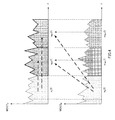
- FIG.4 is provided to explain the selection of the reference signal in selection section 116.
- the horizontal axes in FIG.4 show frequency
- the vertical axes show frequency coefficient (MDCT coefficient) values
- the upper part shows frequency bands of the side residual signal
- the lower part shows frequency bands of the monaural residual signal.
- selection section 116 selects the reference signal where frequency coefficients s M,0 (f) for the 0-th subband part of the side residual signal are predicted, from frequency coefficients m M,0 (f) for the 0-th subband part, frequency coefficients m L (f) for the low band part of the monaural residual signal and frequency coefficients s L '(f) for the low band part of the side residual signal.
- selection section 116 selects the reference signal where frequency coefficients s M,1 (f) for the first subband part of the side residual signal are predicted, from frequency coefficients m M,1 (f) for the first subband part, frequency coefficients m L (f) for the low band part of the monaural residual signal and frequency coefficients s L '(f) for the low band part of the side residual signal.
- FIG.5 is a block diagram showing the configuration of the decoding apparatus according to the present embodiment.
- the bit stream transmitted from coding apparatus 100 shown in FIG.1 is received in decoding apparatus 500 shown in FIG. 5 .
- Demultiplexing section 501 demultiplexes the bit stream received in decoding apparatus, outputs LP parameter coded data to LP parameter decoding section 512, outputs ICP coefficient coded data and reference signal ID coded data to ICP parameter decoding section 503, outputs monaural signal coded data to monaural decoding section 502, and outputs coded data of frequency coefficients for the low band part of a side residual signal to low band decoding section 507.
- Monaural decoding section 502 decodes the monaural signal coded data, to acquire monaural signal M' and monaural residual signal M'res. Monaural decoding section 502 outputs the resulting monaural residual signal M'res to windowing section 504 and outputs monaural signal M' to stereo signal calculation section 514.
- ICP parameter decoding section 503 decodes the ICP coefficient coded data and the reference signal ID coded data, and outputs the acquired ICP coefficients and reference signal ID, to ICP synthesis section 508.
- Windowing section 504 performs windowing on monaural residual signal M'res and outputs the monaural residual signal after windowing to MDCT transformation section 505.
- MDCT transformation section 505 executes MDCT transformation on monaural residual signal M'res after windowing, and outputs resulting frequency coefficients m'(f) of the monaural residual signal to spectrum division section 506.
- Spectrum division section 506 divides the band of frequency coefficients m'(f) for the monaural residual signal into low band part, middle band part and high band part, defining boundaries at predetermined frequencies, and outputs frequency coefficients m' L (f) for the low band part and frequency coefficients m' M (f) for the middle band part of the monaural residual signal to ICP synthesis section 508.
- Low band decoding section 507 decodes the coded data of the frequency coefficients for the low band part of the side residual signal, and outputs resulting frequency coefficients s L '(f) for low band part of the side residual signal to ICP synthesis section 508 and addition section 509.
- ICP synthesis section 508 selects a signal as a reference signal among frequency coefficients m' L (f) of the low band part of the monaural residual signal, frequency coefficients m' M (f) of the middle band part of the monaural residual signal and frequency coefficients s L '(f) of the low band part of the side residual signal. Then, ICP synthesis section 508 calculates frequency coefficients s' M,i (f) of each subband part of the side residual signal by the filtering process represented by following equation 4 using quantization ICP coefficients as filter coefficients, and outputs the frequency coefficients for each subband part of the side residual signal to addition section 509.
- h(i) represents the ICP coefficients
- X(f) represents the reference signal
- P represents the ICP order.
- Addition section 509 combines frequency coefficients s L '(f) of the low band part of the side residual signal and frequency coefficients s' M,i (f) of each subband part of the side residual signal, and outputs resulting frequency coefficients s'(f) of the side residual signal to IMDCT transformation section 510.
- IMDCT transformation section 510 executes IMDCT transformation on frequency coefficients s'(f) of the side residual signal, and outputs the resulting signal to windowing section 511.
- Windowing section 511 performs windowing on the output signal from IMDCT transformation section 510, and outputs resulting side residual signal S'res to LP synthesis section 513.
- LP parameter decoding section 512 decodes the LP parameter coded data and outputs resulting LP coefficients A S to LP synthesis section 513.
- LP synthesis section 513 performs LP synthesis filtering on side residual signal S'res using the LP coefficients A S , to acquire side signal S'.
- Stereo signal calculation section 514 acquires left channel signal L' and right channel signal R' using monaural signal M' and side signal S' by following equations 5 and 6.
- L ⁇ n M ⁇ n + S ⁇ n
- R ⁇ n M ⁇ n - S ⁇ n
- decoding apparatus 500 is able to acquire left channel signal L' and right channel signal R'.
- Decoding apparatus 500 is able to perform decoding processes as long as a bit stream is formed using LP parameter coded data, ICP coefficient coded data, reference signal ID coded data, monaural signal coded data and coded data of frequency coefficients for the low band part of a side residual signal. That is, as long as signals received in decoding apparatus are signals from a coding apparatus that can form these bit streams, the signals may not be transmitted from coding apparatus 100 of FIG.1 .
- selection section 116 will be explained in detail.
- a case where the reference signal is selected based on cross-correlation (the first example) and a case where the reference signal is selected based on predicted gain (the second example) will be explained.
- FIG.6 is a block diagram showing the internal configuration of selection section 116 in the first example.
- Selection section 116 receives as input frequency coefficients s L '(f) for the low band part of the side residual signal, frequency coefficients m M,i (f) for each subband part of the monaural residual signal, frequency coefficients m L (f) for the low band part of the monaural residual signal, frequency coefficients s M,i (f) for each subband part of the side residual signal, the first ICP coefficients, the second ICP coefficients and the third ICP coefficients.
- Correlation check sections 601, 602 and 603 each calculate cross-correlation by following equation 7, and output the correlation values as calculation results to cross-correlation comparison section 604.
- X(j) represents either reference signal candidate, that is, represents frequency coefficients m M,i (f) for each subband part of the monaural residual signal in correlation check section 601, frequency coefficients m L (f) for the low band part of the monaural residual signal in correlation check section 602, and frequency coefficients s L '(f) for the low band part of the side residual signal in correlation check section 603.
- corr ⁇ j j ⁇ s M , i j ⁇ j X ⁇ j 2 ⁇ ⁇ j s M , i ⁇ j 2
- Cross-correlation comparison section 604 selects a reference signal candidate having the highest correlation value as a reference signal, and outputs the reference signal ID showing the selected reference signal to ICP coefficient selection section 605.
- ICP coefficient selection section 605 selects ICP coefficients corresponding to the reference signal ID, and outputs the reference signal ID and the ICP coefficients to ICP parameter quantization section 117.
- FIG.7 is a block diagram showing the internal configuration of selection section 116 in the second example.
- Selection section 116 receives as input frequency coefficients s L '(f) for the low band part of the side residual signal, frequency coefficients m M,i (f) for each subband part of the monaural residual signal, the frequency coefficients m L (f) for the low band part of the monaural residual signal, frequency coefficients s M,i (f) for each subband part of the side residual signal, the first ICP coefficients, the second ICP coefficients and the third ICP coefficients.
- ICP synthesis sections 701, 702 and 703 calculate the frequency coefficients s' M,i (f) of each subband part of the side residual signal corresponding to each reference signal by above equation 4, and output the resulting frequency coefficients to gain check sections 704, 705 and 706.
- Gain check sections 704, 705 and 706 each calculate predicted gain by following equation 8, and outputs the resulting predicted gains to predicted gain comparison section 707.
- e(n) s M,i (f)-s' M,i (f).
- the prediction performance improves when the predicted gain Gain is higher in equation 8.
- Gain 10 ⁇ log 10 ⁇ ⁇ ⁇ s M , i 2 n ⁇ ⁇ e 2 n
- Predicted gain comparison section 707 compares the predicted gains, to select a reference signal candidate having the highest predicted gain as a reference signal, and outputs the reference signal ID showing the selected reference signal to ICP coefficient selection section 708.
- ICP coefficient selection section 708 selects ICP coefficients corresponding to the reference signal ID, and outputs the reference signal ID and the ICP coefficients to ICP parameter quantization section 117.
- a signal providing the optimum prediction result as a reference signal among a plurality of signals and by predicting a residual signal of a side signal using the reference signal, it is possible to improve ICP prediction performance in stereo speech coding.
- quantized ICP coefficients may be used in ICP synthesis.
- selection section 116 receives as input the quantized ICP coefficients quantized by an ICP coefficient quantizer, instead of ICP coefficients before quantization.
- ICP synthesis sections 701, 702 and 703 decode the side signal using quantized ICP coefficients. The predicted gains are compared based on prediction results by the quantized ICP coefficients.
- prediction using quantized ICP coefficients used in a decoding apparatus makes it possible to select the optimum reference signal.
- FIG.8 shows a block diagram showing the configuration of the coding apparatus according to the present embodiment.
- the same reference numerals are assigned to the components in the coding apparatus shown in FIG.1 , and the explanation thereof will be omitted.
- coding apparatus 800 shown in FIG.8 adopts the configuration removing ICP analysis sections 113, 114 and 115 and selection section 116, and adding selection section 801 and ICP analysis section 802.
- selection section 801 selects the optimum signal as a reference signal among the reference signal candidates, and outputs a reference signal ID showing the selected reference signal, to ICP analysis section 802.
- ICP analysis section 802 which is configured with an adaptive filter, performs an ICP analysis using the reference signal and frequency coefficients s M,i (f) of each subband part of the side residual signal, to generate ICP coefficients and outputs these to ICP parameter quantization section 117.
- FIG.9 is a block diagram showing the internal configuration of selection section 801. Compared with the internal configuration of selection section 116 shown in FIG.6 , the internal configuration of selection section 801 shown in FIG.16 adopts a configuration removing ICP coefficient selection section 605.
- Cross-correlation comparison section 604 selects the reference signal candidate having the highest correlation value as a reference signal, and outputs a reference signal ID showing the selected reference signal to ICP analysis section 802.
- ICP coefficients can be calculated after comparing cross-correlation, so that the present embodiment provides the same advantage as in Embodiment 1 and it is possible to reduce the amount of calculation as compared with Embodiment 1.
- modified ICP which is a modified version of conventional ICP, will be explained.
- Modified ICP is provided to solve the problem about the prediction method using a reference signal of a different length from the target signal.
- FIG.10 explains the prediction method in modified ICP in the present embodiment.
- the modified ICP method in the present embodiment is referred to as the "copy method.”
- the length of reference signal X(f) (vector) is represented by N 1 and the length of the target signal is represented by N 2 .
- X(j) represents either reference signal candidate.
- N 1 N 2
- the coding apparatus calculates ICP coefficients using conventional ICP. This case may be applicable to all kinds of reference signals.
- the coding apparatus generates new reference signal X - (f) of a length of N 2 based on original reference signal X(f), predicts the target signal using new reference signal X - (f) and calculates ICP coefficients. Then, the decoding apparatus generates X - (f) using the same method as in the coding apparatus. This case can happen when a low band side signal or a low band monaural signal is selected as the reference signal. The lengths of these signals can be shorter or longer than the target signal.
- the copy method according to the present embodiment solves problems of case 2 above. There are two steps in this copy method.
- Step 1 If N 1 ⁇ N 2 , as shown in FIG.10 , (N 2 -N 1 ) points at the head of vector X(f) are copied to the tail of vector X(f)(of a length of N 1 ), to form new vector X - (f). Further, if N 1 >N 2 , the first N 2 points of vector X(f) are copied to form new reference vector X - (f). X(f) is new reference vector of a length of N 2 .
- Step 2 target signal s M,i (f) is predicted from vector X - (f) using ICP algorithms.
- modified ICP with the present embodiment it is possible to make the subband length of the target signal variable regardless of the length of the reference signal, so that prediction is made possible using a reference signal of a different length from the length of the target signal. That is, it is not necessary to divide entire subband into subbands of the same fixed lengths as the reference signal. Given that low band part of a frequency band has a significant influence upon speech quality is significant, by dividing a low subband into subbands of a shorter length and, conversely, dividing a high frequency subband that becomes relatively less important, into subbands of a longer length and by performing prediction in units of that divided band, it is possible to improve the efficiency of coding and improve sound quality in scalable stereo speech coding.
- modified ICP when a low band side signal is selected as a reference signal, in conventional ICP, it is necessary to encode a reference signal of the same length as the subband of the prediction target and transmit it to the decoder. Meanwhile, with modified ICP according to the present embodiment, it is possible to perform prediction using a reference signal of a shorter bandwidth than the target subband, and, instead of encoding a long reference signal, it is necessary only to encode a short reference signal. Accordingly, modified ICP according to the present embodiment makes it possible to transmit a reference signal to the decoder at low bit rates.
- an alternative method in case 2 in Embodiment 3 (i.e. N 1 ⁇ N 2 or N 1 >N 2 ).
- the prediction method by modified ICP of the present embodiment includes stretching a short reference vector to a new reference vector by interpolation or shortening the reference vector to a shorter vector, using the values of the points in the reference vector.
- the method of modified ICP according to the present embodiment is referred to as "stretching and shortening method.”
- Step 1 If N 1 ⁇ N 2, as shown in FIG.11 , vector X(f) (of a length of N 1 ) is stretched to vector X - (f) of a length of N 2 by following equation 9.
- N 1 ⁇ X k , 0 ⁇ k ⁇ N 1
- Step 2 target signal s M,i (f) is predicted from vector X - (f) using ICP algorithms.
- Embodiment 5 an alternative method of Embodiments 3 and 4 (cases of N 1 ⁇ N 2 or N 1 >N 2 ) will be explained.
- the prediction method by modified ICP according to the present embodiment includes finding periods inside the reference signal and the target signal using long term prediction. New reference signal is generated by duplicating several periods of the original reference signal based on the resulting period.
- Step 1 reference signal X(f) and target signal s M,i (f) are concatenated, to acquire continued vector X L (f). It is assumed that a period is present inside the vector X L (f). Period T is found by minimizing error err in following equation 11. Period T can be found by using other period calculation algorithms such as an autocorrelation method, and magnitude difference function (see Non-Patent Document 5).
- Step 2 target signal s M,i (f) is predicted from vector X - (f) using ICP algorithms.
- information about period T is needed to be transmitted to the decoding apparatus.
- Embodiments 3, 4 and 5 upon dividing the middle band of the side residual signal into subbands and performing prediction, when the low band part of the side residual signal is selected as a reference signal by performing prediction continuously from a subband on the low band side to a subband on the high band side, a reference signal of a desired length may be generated also using a subband signal already predicted in advance on the low band side.
- the method according to the present invention can be referred to as "ACP: Adaptive Channel Prediction,” by selecting a signal providing the optimum prediction result as a reference signal among a plurality of signals and by predicting a side residual signal using the reference signal in ICP.
- ACP Adaptive Channel Prediction
- the monaural signal encoder/decoder is a transform coder, such as MDCT transform coder
- a decoded monaural signal (or decoded monaural LP residual signal) in the MDCT domain is directly acquired from a monaural encoder on the encoder side and from a monaural decoder at the decoder side.
- the coding scheme described in the above embodiments uses monaural signals to predict side signals.
- This scheme is referred to as the "M-S type.”
- a left or right signal may be predicted using a monaural signal.
- the operations in this case are virtually the same as those of the M-S type process in the above embodiments except that the side channel is replaced by the left or right channel (i.e. L or R is regarded as S) and the left (or right) channel signal is encoded.
- the signal of one channel (the right or left channel) of the other channel coded on the coding side (the left or right channel) is calculated in the decoder using the decoded channel signal (left or right channel signal) and the monaural signal as in following equations 12 and 13.
- L n 2 ⁇ M n - R n where the coding target is the right R channel
- the weighted sum of those may be used (i.e. the signal in which three kinds of signals are added after multiplying them by a predetermined weighing factor).
- all the three reference signal candidates are not necessarily used, and, for example, only two of them, a monaural signal in the middle band and a side signal in the low band may be used as candidates. This makes it possible to reduce the number of bits to transmit a reference signal ID.
- side signals are predicted on a per frame basis.
- a middle band signal is predicted from a signal in the same frame on the other frequency band.
- inter-frame prediction can also be used.
- the past frames can be used as a reference candidate to predict a current frame signal.
- the target signal as the target of prediction is a middle band side signal except a low band and a high band
- the present invention is not limited to this, and, the target signal may include all signal bands including middle bands and high bands except low bands. Further, all signal bands including low signal bands may be the target. Even in these cases, the prediction can be performed by dividing an arbitrary band of the side signal into small subbands. This will not change structures of the encoder and the decoder.
- a reference signal can be selected from several subband signals in the time domain (e.g. acquired by QMF: Quadrature Mirror Filter), to predict a middle (or high) band signal in the time domain.
- QMF Quadrature Mirror Filter
- the coding apparatus and the decoding apparatus according to the present invention can be provided in a communication terminal apparatus and base station apparatus in a mobile communication system, so that it is possible to provide a communication terminal apparatus, base station apparatus and mobile communication system having same advantages and effects as described above.
- the present invention can also be realized by software.
- Each function block employed in the description of each of the aforementioned embodiments may typically be implemented as an LSI constituted by an integrated circuit. These may be individual chips or partially or totally contained on a single chip.
- LSI is adopted here but this may also be referred to as “IC,” “system LSI,” “super LSI,” or “ultra LSI” depending on differing extents of integration.
- circuit integration is not limited to LSIs, and implementation using dedicated circuitry or general purpose processors is also possible.
- LSI manufacture utilization of a programmable FPGA (Field Programmable Gate Array) or a reconfigurable process or where connections and settings of circuit cells within an LSI can be reconfigured is also possible.
- FPGA Field Programmable Gate Array
- the coding apparatus and the coding method according to the present invention is suitable for use in mobile phones, IP phones, video conferences and so on.
Landscapes
- Engineering & Computer Science (AREA)
- Physics & Mathematics (AREA)
- Computational Linguistics (AREA)
- Signal Processing (AREA)
- Health & Medical Sciences (AREA)
- Audiology, Speech & Language Pathology (AREA)
- Human Computer Interaction (AREA)
- Acoustics & Sound (AREA)
- Multimedia (AREA)
- Mathematical Physics (AREA)
- Quality & Reliability (AREA)
- Compression, Expansion, Code Conversion, And Decoders (AREA)
Abstract
Description
- The present invention relates to a coding apparatus and a decoding apparatus that realize scalable stereo speech coding using inter-channel prediction (ICP).
- Conventionally, speech coding (speech codec) is used for communication applications using telephony narrowband speech (200 Hz to 3.4 kHz). Monophonic narrowband speech codec is widely used in communication applications including voice communication using mobile phones, teleconferencing equipment and packet networks (e.g. Internet).
- One of steps towards more realistic speech communication system is the move from monophonic speech representation to stereophonic speech representation. Wideband stereophonic communications provide a more natural sounding environment. Scalable stereo speech coding is a core technology for realizing voice communications with superior quality and usability.
- One of popular methods of encoding a stereo speech signal is attributed to employing a signal prediction scheme based on a monaural speech. That is, a reference channel signal is transmitted using known monaural speech codec, and the left or right channel is predicted from this reference channel signal using additional information and parameters. In many applications, a monaural signal in which a left channel signal and right channel signal are mixed is selected as the reference channel signal.
- As stereo signal coding methods including intensity stereo coding (ISC), binaural cue coding (BCC) and inter-channel prediction (ICP) are known. These parametric stereo coding methods all have different strengths and weaknesses and are suitable for encoding different source materials.
- Non-Patent
Document 1 discloses a technique of predicting stereo signals based on monaural signals using these coding methods. Specifically, a monaural signal is acquired by synthesizing channel signals forming stereo signals (e.g. a left channel signal and a right channel signal), the acquired monaural signal is encoded/decoded using known speech codec, and, furthermore, from the monaural signal, a difference signal between the left channel and the right channel (i.e. a side signal) is predicted using prediction parameters. With this coding method, the coding side models the relationships between a monaural signal and a side signal using time-dependent adaptive filters and transmits filter coefficients calculated per frame to the decoding side. By filtering a high-quality monaural signal transmitted by monaural codec, the decoding side regenerates the difference signal and calculates the left channel signal and right channel signal from the regenerated difference signal and the monaural signal. - Further, Non-Patent Document 2 discloses a coding method referred to as "cross-channel correlation canceller" whereby, by applying a technique of cross-channel correlation canceller to the ICP scheme coding method, it is possible to predict one channel from the other channel.
- Further, in recent years, an audio compression technique is rapidly developed, a modified discrete cosine transform (MDCT) scheme has been becoming a major technique of high-quality audio coding (see Non-Patent Documents 3 and 4).
- MDCT has been applied to audio compression without major auditory problems if a proper window such as a sine window is employed. Recently, MDCT plays an important role in multimode transform predictive coding paradigms.
- The multimode transform predictive coding refers to combining speech and audio coding principles in a single coding structure (see Non-Patent Document 4). It should be noted that the MDCT-based coding structure and application in Non-Patent Document 4 are designed for encoding signals in only one channel, and quantize MDCT coefficients in different frequency regions using different quantization schemes.
Non-Patent Document 1: Extended AMR Wideband Speech Codec (AMR-WB+): Transcoding functions, 3GPP TS 26.290. Non-Patent Document 2: S. Minami and O. Okada, "Stereophonic ADPCM voice coding method," in Proc. ICASSP'90, Apr. 1990. Non-Patent Document 3: Ye Wang and Miikka Vilermo, "The modified discrete cosine transform: its implications for audio coding and error concealment," in AES 22nd International Conference on Virtual, Synthetic and Entertainment, 2002. Non-Patent Document 4: Sean A. Ramprashad, "The multimode transform predictive coding paradigm," IEEE Tran. Speech and Audio Processing, vol. 11, pp. 117 - 129, Mar. 2003.
Non-Patent Document 5: Wai C. Chu, "Speech coding algorithms: foundation and evolution of standardized coders", ISBN 0-471-37312-5, 2003 - In a case where the coding scheme in Non-Patent Document 2 is employed, when the correlation between the two channels is high, the performance of ICP is sufficient. However, when the correlation is low, higher order adaptive filter coefficients are needed, and, in some cases, it costs too much to improve the predicted gain. Unless the filter order is increased, the energy level of an prediction error may be the same as the energy level of a reference signal, and ICP is not useful in such a situation.
- The low frequency part of a frequency band is essentially important to speech signal quality. Small errors in the low frequency part of the decoded speech damage the whole speech quality severely. Due to the limitations of prediction performance of ICP in speech coding, it is difficult to achieve satisfied performance for low frequency part when the correlation between the two channels is not high, and it is desirable to employ other coding schemes.
- With
Non-Patent Document 1, ICP is applied only to signals of high frequency band part in the time domain. This is one solution to the above problem. However, an input monaural signal is used for ICP at the encoder withNon-Patent Document 1. Preferably, a decoded monaural signal should be used. This is because on the decoder side, regenerated stereo signals are acquired by an ICP synthesis filter that uses monaural signals decoded by the monaural decoder. However, if the monaural encoder is a type of a transform coder which is widely used especially for wideband audio coding (7 kHz or above) such as MDCT transform coding, to acquire time-domain decoded monaural signals on the encoder side, some additional algorithmic delay is produced. - It is therefore an object of the present invention to provide a coding apparatus and a decoding apparatus that realize scalable stereo speech coding using inter-channel prediction (ICP) and improve ICP prediction performance in stereo speech coding.
- The coding apparatus of the present invention adopts the configuration including: a monaural signal generation section that synthesizes a first channel signal and a second channel signal in a stereo signal, to generate a monaural signal, and generates a side signal, the side signal being a difference between the first channel signal and the second channel signal; a side residual signal acquiring section that acquires a side residual signal, the side residual signal being a linear prediction residual signal for the side signal; a monaural residual signal acquiring section that acquires a monaural residual signal, the monaural residual signal being a linear prediction residual signal for the monaural signal; a first spectrum division section that divides the side residual signal into a low band part being a lower band than a predetermined frequency and a middle band part being a higher band than the predetermined frequency; a second spectrum division section that divides the monaural residual signal into a low band part being a lower band than a predetermined frequency and a middle band part being a higher band than the predetermined frequency; a selection section that selects an optimal signal as a reference signal from reference signal candidates by checking relationships between each reference signal candidate and a target signal, the reference signal candidates being frequency coefficients for the low band part of the side residual signal, frequency coefficients for the middle band part of the monaural residual signal, and frequency coefficients for the low band part of the monaural residual signal, and the target signal being frequency coefficients for the middle band part of the side residual signal; and an inter channel prediction analysis section that performs an inter-channel prediction analysis between the reference signal and the target signal, to acquire inter-channel prediction coefficients.
- The decoding apparatus of the present invention adopts the configuration including: an inter-channel prediction synthesis section that selects a reference signal from: frequency coefficients for a low band part being a lower band than a predetermined frequency of a side residual signal, the side residual signal being a linear prediction residual signal for a side signal being a difference between a first channel signal and a second channel signal in a stereo signal; frequency coefficients for a middle band part being a higher band than a predetermined frequency of a monaural residual signal, the monaural residual signal being the linear prediction residual signal for a monaural signal generated by synthesizing the first channel signal and the second channel signal; and frequency coefficients for the low band part lower band than a predetermined frequency of the monaural residual signal, and that calculates the frequency coefficients for the middle band part of the side residual signal by filtering the reference signal using inter-channel prediction coefficients as filter coefficients acquired by performing an inter-channel prediction analysis between the reference signal and the frequency coefficients for the middle band part being a higher band than the predetermined frequency of the side residual signal; an addition section that adds the frequency coefficients for the low band part of the side residual signal and the frequency coefficients for the middle band part of the side residual signal, to acquire frequency coefficients for an entire band of the side residual signal; a linear prediction synthesis section that performs linear prediction synthesis filtering for the side residual signal, to acquire the side signal; and a stereo signal calculation section that acquires the first channel signal and the second channel signal using the monaural signal and the side signal.
- The coding method of the present invention includes the steps of: a monaural signal generation step of synthesizing a first channel signal and a second channel signal in a stereo signal, to generate a monaural signal, and generating a side signal, the side signal being a difference between the first channel signal and the second channel signal; a side residual signal acquiring step of acquiring a side residual signal, the side residual signal being a linear prediction residual signal for the side signal; a monaural residual signal acquiring step of acquiring a monaural residual signal, the monaural residual signal being a linear prediction residual signal for the monaural signal; a first spectrum division step of dividing the side residual signal into a low band part being a lower band than a predetermined frequency and a middle band part being a higher band than the predetermined frequency; a second spectrum division step of dividing the monaural residual signal into a low band part being a lower band than a predetermined frequency and a middle band part being a higher band than the predetermined frequency; a selection step of selecting an optimal signal as a reference signal from reference signal candidates by checking relationships between each reference signal candidate and a target signal, the reference signal candidates being frequency coefficients for the low band part of the side residual signal, frequency coefficients for the middle band part of the monaural residual signal, and frequency coefficients for the low band part of the monaural residual signal, and the target signal being frequency coefficients for the middle band part of the side residual signal; and an inter channel prediction analysis step of performing an inter-channel prediction analysis between the reference signal and the target signal, to acquire inter-channel prediction coefficients.
- The decoding method of the present invention includes the steps of: an inter-channel prediction synthesis step of selecting a reference signal from: frequency coefficients for a low band part being a lower band than a predetermined frequency of a side residual signal, the side residual signal being a linear prediction residual signal for a side signal being a difference between a first channel signal and a second channel signal in a stereo signal; frequency coefficients for a middle band part being a higher band than a predetermined frequency of a monaural residual signal, the monaural residual signal being the linear prediction residual signal for a monaural signal generated by synthesizing the first channel signal and the second channel signal; and frequency coefficients for the low band part lower band than a predetermined frequency of the monaural residual signal, and that calculates the frequency coefficients for the middle band part of the side residual signal by filtering the reference signal using inter-channel prediction coefficients as filter coefficients acquired by performing an inter-channel prediction analysis between the reference signal and the frequency coefficients for the middle band part being a higher band than the predetermined frequency of the side residual signal; an addition step of adding the frequency coefficients for the low band part of the side residual signal and the frequency coefficients for the middle band part of the side residual signal, to acquire frequency coefficients for an entire band of the side residual signal; a linear prediction synthesis step of performing linear prediction synthesis filtering for the side residual signal, to acquire the side signal; and a stereo signal calculation step of acquiring the first channel signal and the second channel signal using the monaural signal and the side signal.
- According to the present invention, by selecting a signal providing the optimum prediction result as a reference signal among a plurality of signals and by predicting a residual signal of a side signal using the reference signal, it is possible to improve ICP prediction performance in stereo speech coding.
-
-
FIG.1 is a block diagram showing a configuration of the coding apparatus according toEmbodiment 1 of the present invention; -
FIG.2 is a block diagram showing the main internal configuration of the ICP analysis section according toEmbodiment 1 of the present invention; -
FIG.3 shows an example of an adaptive FIR filter used in ICP analysis and ICP synthesis; -
FIG.4 is provided to explain the selection of a reference signal in the selection section of the coding apparatus according toEmbodiment 1 of the present invention; -
FIG.5 is a block diagram showing a configuration of the decoding apparatus according toEmbodiment 1 of the present invention; -
FIG.6 is a block diagram showing the internal configuration of the selection section in the first example of the coding apparatus according toEmbodiment 1 of the present invention; -
FIG.7 is a block diagram showing the internal configuration of the selection section in a second example of the coding apparatus according toEmbodiment 1 of the present invention; -
FIG.8 is a block diagram showing a configuration of the coding apparatus according to Embodiment 2 of the present invention; -
FIG.9 is a block diagram showing the internal configuration of the selection section in the coding apparatus according to Embodiment 2 of the present invention; -
FIG.10 explains the prediction method in modified ICP according to Embodiment 3 of the present invention; and -
FIG.11 explains the prediction method in modified ICP according to Embodiment 4 of the present invention. - Now, embodiments of the present invention will be described in detail with reference to the accompanying drawings. In the following explanation, a left channel signal, a right channel signal, a monaural signal and a side signal are represented as "L," "R," "M," and "S," respectively, and their regenerated signals are represented as "L'," "R'," "M'," and "S'," respectively. Further, with the following explanation, the length of each frame is represented as "N," and MDCT domain signals (referred to as "frequency coefficients" or "MDCT coefficients") for a monaural signal and a side signal are represented as m(f) and s(f), respectively.
-
FIG.1 is a block diagram showing the configuration of the coding apparatus according to the present embodiment.Coding apparatus 100 shown inFIG.1 receives as input stereo signals formed with the left channel signal and the right channel signal in the PCM scheme on a per frame basis. - Monaural
signal synthesis section 101 synthesizes left channel signal L and right channel signal R by followingequation 1, to generate monaural signal M. Moreover, monauralsignal synthesis section 101 generates side signal S from following equation 2 using left channel signal L and right channel signal R. Then, monauralsignal synthesis section 101 outputs side signal S to LP analysis andquantization section 102 and LPinverse filter 103, and outputs monaural signal M tomonaural coding section 104.


- In these
equations 1 and 2, n represents a time index in a frame. The synthesis method to generate a monaural signal is not limited toequation 1. For example, it is equally possible to generate a monaural signal using other methods, for example, a method of adaptively weighting and mixing signals. - LP analysis and
quantization section 102 calculates LP parameters based on LP analysis (linear prediction analysis) and quantizes those LP parameters for side signal S, and outputs coded data of the resulting LP parameters tomultiplexing section 118 and resulting LP coefficients As to LPinverse filter 103. - LP
inverse filter 103 performs LP inverse filtering for side signal S using LP coefficients As, and outputs the residual signal of the resulting side signal (hereinafter "side residual signal") towindowing section 105. -
Monaural coding section 104 encodes monaural signal M, and outputs the resulting coded data to multiplexingsection 118. In addition,monaural coding section 104 outputs monaural residual signal Mres towindowing section 106. A residual signal may also be referred to as an "excitation signal." This residual signal can be extracted in most monaural speech coding apparatuses (e.g. CELP (Code Excited Linear Prediction)-based coding apparatuses) or in coding apparatuses of the type including the process of generating an LP residual signal or a residual signal subject to local decoding. -
Windowing section 105 performs windowing on side residual signal Sres, and outputs the side residual signal after windowing toMDCT transformation section 107.Windowing section 106 performs windowing on monaural residual signal Mres, and outputs the monaural residual signal after windowing toMDCT transformation section 108. -
MDCT transformation section 107 executes MDCT transformation on side residual signal Sres after windowing, and outputs resulting frequency coefficients s(f) of the side residual signal tospectrum division section 109.MDCT transformation section 108 executes MDCT transformation on monaural residual signal Mres after windowing, and outputs resulting frequency coefficients m(f) of the monaural residual signal tospectrum division section 110. -
Spectrum division section 109 divides the band of frequency coefficients s(f) for the side residual signal into low band part, middle band part and high band part, defining boundaries at predetermined frequencies, and outputs frequency coefficients sL(f) for the low band part of the side residual signal to lowband coding section 111. In addition,spectrum division section 109 further divides the middle band part of the side residual signal into smaller subbands i, and outputs frequency coefficients sM,i(f) for each subband part of the side residual signal toICP analysis sections -
Spectrum division section 110 divides the band of frequency coefficients m(f) for the monaural residual signal into low band part, middle band part and high band part, defining boundaries at predetermined frequencies, and outputs frequency coefficients mL(f) for the low band part of the monaural residual signal toICP analysis section 115. In addition,spectrum division section 110 further divides the middle band part of the monaural residual signal into smaller subbands i, and outputs frequency coefficients mM,i(f) for each subband part of the side residual signal toICP analysis section 114. - Low
band coding section 111 encodes frequency coefficients sL(f) for the low band part of the side residual signal, and outputs the resulting coded data to lowband decoding section 112 andmultiplexing section 118. - Low
band decoding section 112 decodes the coded data of the frequency coefficients for the low band part of the side residual signal, and outputs resulting frequency coefficients sL'(f) for low band part of the side residual signal toICP analysis section 113 andselection section 116. -
ICP analysis section 113, which is configured with an adaptive filter, performs an ICP analysis of frequency coefficients sL'(f) for low band part of the side residual signal as a reference signal candidate and frequency coefficients sM,i(f) for each subband part of the side residual signal, to generate the first ICP coefficients, and outputs these toselection section 116. -
ICP analysis section 114, which is configured with an adaptive filter, performs an ICP analysis of frequency coefficients mM,i(f) for each subband part of the monaural residual signal as a reference signal candidate and frequency coefficients sM,i(f) for each subband part of the side residual signal, to generate second ICP coefficients, and outputs these toselection section 116. -
ICP analysis section 115, which is configured with an adaptive filter, performs an ICP analysis of frequency coefficients mL(f) for low band part of the monaural residual signal as a reference signal candidate and frequency coefficients sM,i(f) for each subband part of the side residual signal, to generate third ICP coefficients, and outputs these toselection section 116. - By checking the relationships between each reference signal candidate and frequency coefficients sM,i(f) for each subband part of the side residual signal,
selection section 116 selects the optimum signal as a reference signal among the reference signal candidates, and outputs a reference signal ID (identification) showing the selected reference signal and ICP coefficients corresponding to the selected signal to ICPparameter quantization section 117. The internal configuration ofselection section 116 will be described later in detail. - ICP
parameter quantization section 117 quantizes the ICP coefficients outputted fromselection section 116, to encode the reference signal ID. Coded data for the quantized ICP coefficients and coded data for reference signal ID are outputted to multiplexingsection 118. - Multiplexing
section 118 multiplexes the coded data of the LP parameters outputted from LP analysis andquantization section 102, the coded data of the monaural signal outputted frommonaural coding section 104, the coded data of frequency coefficients for the low band part of the side residual signal outputted from lowband coding section 111, and the coded data of the quantized ICP coefficients and the coded data of reference signal ID outputted from ICPparameter quantization section 117, to output the resulting bit stream. -
FIG.2 shows the configuration and operations of adaptive filters formingICP analysis sections ICP analysis section 113, x(n) corresponds to sL'(f) and y(n) corresponds to sM,i(f). - Based on following equation 3, the adaptive filter finds and outputs adaptive filter parameters b=[b0,b1,...,bk] such that the mean squared error (MSE) between a prediction signal and the target signal is the minimum. In equation 3, E{ } represents the ensemble average operation, k represents the filter order, and e(n) represents the prediction error.

- H(z) in
FIG.2 has many other configurations.FIG.3 shows one of them. The filter configuration shown inFIG.3 is a conventional FIR filter. -
FIG.4 is provided to explain the selection of the reference signal inselection section 116.FIG.4 shows a case where the number of subbands is 2(i=0,1). The horizontal axes inFIG.4 show frequency, the vertical axes show frequency coefficient (MDCT coefficient) values, the upper part shows frequency bands of the side residual signal and the lower part shows frequency bands of the monaural residual signal. - In this case,
selection section 116 selects the reference signal where frequency coefficients sM,0(f) for the 0-th subband part of the side residual signal are predicted, from frequency coefficients mM,0(f) for the 0-th subband part, frequency coefficients mL(f) for the low band part of the monaural residual signal and frequency coefficients sL'(f) for the low band part of the side residual signal. Likewise,selection section 116 selects the reference signal where frequency coefficients sM,1(f) for the first subband part of the side residual signal are predicted, from frequency coefficients mM,1(f) for the first subband part, frequency coefficients mL(f) for the low band part of the monaural residual signal and frequency coefficients sL'(f) for the low band part of the side residual signal. -
FIG.5 is a block diagram showing the configuration of the decoding apparatus according to the present embodiment. The bit stream transmitted fromcoding apparatus 100 shown inFIG.1 is received indecoding apparatus 500 shown inFIG. 5 . -
Demultiplexing section 501 demultiplexes the bit stream received in decoding apparatus, outputs LP parameter coded data to LPparameter decoding section 512, outputs ICP coefficient coded data and reference signal ID coded data to ICPparameter decoding section 503, outputs monaural signal coded data tomonaural decoding section 502, and outputs coded data of frequency coefficients for the low band part of a side residual signal to lowband decoding section 507. -
Monaural decoding section 502 decodes the monaural signal coded data, to acquire monaural signal M' and monaural residual signal M'res.Monaural decoding section 502 outputs the resulting monaural residual signal M'res towindowing section 504 and outputs monaural signal M' to stereosignal calculation section 514. - ICP
parameter decoding section 503 decodes the ICP coefficient coded data and the reference signal ID coded data, and outputs the acquired ICP coefficients and reference signal ID, toICP synthesis section 508. -
Windowing section 504 performs windowing on monaural residual signal M'res and outputs the monaural residual signal after windowing toMDCT transformation section 505.MDCT transformation section 505 executes MDCT transformation on monaural residual signal M'res after windowing, and outputs resulting frequency coefficients m'(f) of the monaural residual signal tospectrum division section 506. -
Spectrum division section 506 divides the band of frequency coefficients m'(f) for the monaural residual signal into low band part, middle band part and high band part, defining boundaries at predetermined frequencies, and outputs frequency coefficients m'L(f) for the low band part and frequency coefficients m'M(f) for the middle band part of the monaural residual signal toICP synthesis section 508. - Low
band decoding section 507 decodes the coded data of the frequency coefficients for the low band part of the side residual signal, and outputs resulting frequency coefficients sL'(f) for low band part of the side residual signal toICP synthesis section 508 andaddition section 509. - Based on the reference signal ID,
ICP synthesis section 508 selects a signal as a reference signal among frequency coefficients m'L(f) of the low band part of the monaural residual signal, frequency coefficients m'M(f) of the middle band part of the monaural residual signal and frequency coefficients sL'(f) of the low band part of the side residual signal. Then,ICP synthesis section 508 calculates frequency coefficients s'M,i(f) of each subband part of the side residual signal by the filtering process represented by following equation 4 using quantization ICP coefficients as filter coefficients, and outputs the frequency coefficients for each subband part of the side residual signal toaddition section 509. In equation 4, h(i) represents the ICP coefficients, X(f) represents the reference signal, and P represents the ICP order.
-
Addition section 509 combines frequency coefficients sL'(f) of the low band part of the side residual signal and frequency coefficients s'M,i(f) of each subband part of the side residual signal, and outputs resulting frequency coefficients s'(f) of the side residual signal toIMDCT transformation section 510. -
IMDCT transformation section 510 executes IMDCT transformation on frequency coefficients s'(f) of the side residual signal, and outputs the resulting signal towindowing section 511.Windowing section 511 performs windowing on the output signal fromIMDCT transformation section 510, and outputs resulting side residual signal S'res toLP synthesis section 513. - LP
parameter decoding section 512 decodes the LP parameter coded data and outputs resulting LP coefficients AS toLP synthesis section 513. -
LP synthesis section 513 performs LP synthesis filtering on side residual signal S'res using the LP coefficients AS, to acquire side signal S'. - Stereo
signal calculation section 514 acquires left channel signal L' and right channel signal R' using monaural signal M' and side signal S' by followingequations 5 and 6.


- In this way, by decoding a received signal from
coding apparatus 100 inFIG.1 ,decoding apparatus 500 is able to acquire left channel signal L' and right channel signal R'.Decoding apparatus 500 is able to perform decoding processes as long as a bit stream is formed using LP parameter coded data, ICP coefficient coded data, reference signal ID coded data, monaural signal coded data and coded data of frequency coefficients for the low band part of a side residual signal. That is, as long as signals received in decoding apparatus are signals from a coding apparatus that can form these bit streams, the signals may not be transmitted fromcoding apparatus 100 ofFIG.1 . - Next, the internal configuration of
selection section 116 will be explained in detail. With the present embodiment, a case where the reference signal is selected based on cross-correlation (the first example) and a case where the reference signal is selected based on predicted gain (the second example) will be explained. -
FIG.6 is a block diagram showing the internal configuration ofselection section 116 in the first example.Selection section 116 receives as input frequency coefficients sL'(f) for the low band part of the side residual signal, frequency coefficients mM,i(f) for each subband part of the monaural residual signal, frequency coefficients mL(f) for the low band part of the monaural residual signal, frequency coefficients sM,i(f) for each subband part of the side residual signal, the first ICP coefficients, the second ICP coefficients and the third ICP coefficients. -
Correlation check sections cross-correlation comparison section 604. Here, in equation 7, X(j) represents either reference signal candidate, that is, represents frequency coefficients mM,i(f) for each subband part of the monaural residual signal incorrelation check section 601, frequency coefficients mL(f) for the low band part of the monaural residual signal incorrelation check section 602, and frequency coefficients sL'(f) for the low band part of the side residual signal incorrelation check section 603.

-
Cross-correlation comparison section 604 selects a reference signal candidate having the highest correlation value as a reference signal, and outputs the reference signal ID showing the selected reference signal to ICPcoefficient selection section 605. - ICP
coefficient selection section 605 selects ICP coefficients corresponding to the reference signal ID, and outputs the reference signal ID and the ICP coefficients to ICPparameter quantization section 117. -
FIG.7 is a block diagram showing the internal configuration ofselection section 116 in the second example.Selection section 116 receives as input frequency coefficients sL'(f) for the low band part of the side residual signal, frequency coefficients mM,i(f) for each subband part of the monaural residual signal, the frequency coefficients mL(f) for the low band part of the monaural residual signal, frequency coefficients sM,i(f) for each subband part of the side residual signal, the first ICP coefficients, the second ICP coefficients and the third ICP coefficients. -
ICP synthesis sections check sections -
Gain check sections gain comparison section 707. Here, in equation 8, e(n)=sM,i(f)-s'M,i(f). The prediction performance improves when the predicted gain Gain is higher in equation 8.

- Predicted
gain comparison section 707 compares the predicted gains, to select a reference signal candidate having the highest predicted gain as a reference signal, and outputs the reference signal ID showing the selected reference signal to ICPcoefficient selection section 708. - ICP
coefficient selection section 708 selects ICP coefficients corresponding to the reference signal ID, and outputs the reference signal ID and the ICP coefficients to ICPparameter quantization section 117. - As described above, according to the present embodiment, by selecting a signal providing the optimum prediction result as a reference signal among a plurality of signals and by predicting a residual signal of a side signal using the reference signal, it is possible to improve ICP prediction performance in stereo speech coding.
- In the above second example, quantized ICP coefficients may be used in ICP synthesis. In this case,
selection section 116 receives as input the quantized ICP coefficients quantized by an ICP coefficient quantizer, instead of ICP coefficients before quantization.ICP synthesis sections - With Embodiment 2 of the present invention, a case will be explained where ICP coefficients are calculated after comparing cross-correlation.
FIG.8 shows a block diagram showing the configuration of the coding apparatus according to the present embodiment. In the coding apparatus inFIG.8 , the same reference numerals are assigned to the components in the coding apparatus shown inFIG.1 , and the explanation thereof will be omitted. Compared withcoding apparatus 100 shown inFIG.1 ,coding apparatus 800 shown inFIG.8 adopts the configuration removingICP analysis sections selection section 116, and addingselection section 801 andICP analysis section 802. - By checking the relationships between reference signal candidates and the frequency coefficients sM,i(f) of each subband part of the side residual signal,
selection section 801 selects the optimum signal as a reference signal among the reference signal candidates, and outputs a reference signal ID showing the selected reference signal, toICP analysis section 802. -
ICP analysis section 802, which is configured with an adaptive filter, performs an ICP analysis using the reference signal and frequency coefficients sM,i(f) of each subband part of the side residual signal, to generate ICP coefficients and outputs these to ICPparameter quantization section 117. -
FIG.9 is a block diagram showing the internal configuration ofselection section 801. Compared with the internal configuration ofselection section 116 shown inFIG.6 , the internal configuration ofselection section 801 shown in FIG.16 adopts a configuration removing ICPcoefficient selection section 605. -
Cross-correlation comparison section 604 selects the reference signal candidate having the highest correlation value as a reference signal, and outputs a reference signal ID showing the selected reference signal toICP analysis section 802. - In this way, according to the present embodiment, ICP coefficients can be calculated after comparing cross-correlation, so that the present embodiment provides the same advantage as in
Embodiment 1 and it is possible to reduce the amount of calculation as compared withEmbodiment 1. - In Embodiment 3, modified ICP, which is a modified version of conventional ICP, will be explained. Modified ICP is provided to solve the problem about the prediction method using a reference signal of a different length from the target signal.
-
FIG.10 explains the prediction method in modified ICP in the present embodiment. The modified ICP method in the present embodiment is referred to as the "copy method." InFIG.10 , the length of reference signal X(f) (vector) is represented by N1 and the length of the target signal is represented by N2. X(j) represents either reference signal candidate. - Two cases are taken into account in modified ICP.
- Case 1: N1=N2
In this case, the coding apparatus calculates ICP coefficients using conventional ICP. This case may be applicable to all kinds of reference signals. - Case 2: N1<N2 or N1>N2
- In this case, the coding apparatus generates new reference signal X-(f) of a length of N2 based on original reference signal X(f), predicts the target signal using new reference signal X-(f) and calculates ICP coefficients. Then, the decoding apparatus generates X-(f) using the same method as in the coding apparatus. This case can happen when a low band side signal or a low band monaural signal is selected as the reference signal. The lengths of these signals can be shorter or longer than the target signal.
- The copy method according to the present embodiment solves problems of case 2 above. There are two steps in this copy method.
- Step 1: If N1<N2, as shown in
FIG.10 , (N2-N1) points at the head of vector X(f) are copied to the tail of vector X(f)(of a length of N1), to form new vector X-(f). Further, if N1>N2, the first N2 points of vector X(f) are copied to form new reference vector X-(f). X(f) is new reference vector of a length of N2. - Step 2: target signal sM,i(f) is predicted from vector X-(f) using ICP algorithms.
- In this way, according to modified ICP with the present embodiment, it is possible to make the subband length of the target signal variable regardless of the length of the reference signal, so that prediction is made possible using a reference signal of a different length from the length of the target signal. That is, it is not necessary to divide entire subband into subbands of the same fixed lengths as the reference signal. Given that low band part of a frequency band has a significant influence upon speech quality is significant, by dividing a low subband into subbands of a shorter length and, conversely, dividing a high frequency subband that becomes relatively less important, into subbands of a longer length and by performing prediction in units of that divided band, it is possible to improve the efficiency of coding and improve sound quality in scalable stereo speech coding.
- Further, when a low band side signal is selected as a reference signal, in conventional ICP, it is necessary to encode a reference signal of the same length as the subband of the prediction target and transmit it to the decoder. Meanwhile, with modified ICP according to the present embodiment, it is possible to perform prediction using a reference signal of a shorter bandwidth than the target subband, and, instead of encoding a long reference signal, it is necessary only to encode a short reference signal. Accordingly, modified ICP according to the present embodiment makes it possible to transmit a reference signal to the decoder at low bit rates.
- With Embodiment 4, an alternative method in case 2 in Embodiment 3 (i.e. N1<N2 or N1>N2). The prediction method by modified ICP of the present embodiment includes stretching a short reference vector to a new reference vector by interpolation or shortening the reference vector to a shorter vector, using the values of the points in the reference vector. The method of modified ICP according to the present embodiment is referred to as "stretching and shortening method."
- There are two steps in this stretching and shortening method according to the present embodiment.
- Step 1: If N1<N2, as shown in
FIG.11 , vector X(f) (of a length of N1) is stretched to vector X-(f) of a length of N2 by following equation 9.

- One of various interpolation methods such as nearest neighbor interpolation, linear interpolation, cubic spline interpolation, and Lagrange interpolation can be applied to X-(f) to find the value where points of vector X-(f) are missing. Further, if N1>N2, vector X(f) (of a length of N1) is shortened to vector X-(f) of a length of N2 by following equation 10.

- Step 2: target signal sM,i(f) is predicted from vector X-(f) using ICP algorithms.
- With
Embodiment 5, an alternative method of Embodiments 3 and 4 (cases of N1<N2 or N1>N2) will be explained. The prediction method by modified ICP according to the present embodiment includes finding periods inside the reference signal and the target signal using long term prediction. New reference signal is generated by duplicating several periods of the original reference signal based on the resulting period. - There are two steps in the method according to the present embodiment.
- Step 1: reference signal X(f) and target signal sM,i(f) are concatenated, to acquire continued vector XL(f). It is assumed that a period is present inside the vector XL(f). Period T is found by minimizing error err in following equation 11. Period T can be found by using other period calculation algorithms such as an autocorrelation method, and magnitude difference function (see Non-Patent Document 5).

- If T>min[N1,N2], then let T=min[N1,N2]. Based on T, a signal of a length of T from X(f) is copied one time or a few times, to obtain new reference signal X-(f) of a length of N2.
- Step 2: target signal sM,i(f) is predicted from vector X-(f) using ICP algorithms.
- To use the method according to the present embodiment, information about period T is needed to be transmitted to the decoding apparatus.
- Although cases have been explained with
Embodiments 3, 4 and 5 where, when the low band part of the monaural residual signal is selected as a reference signal, prediction is performed after the generation of the reference signal of an expanded length of the monaural residual signal using one of methods according to the above embodiments, with the present invention, a reference signal of a desired length may be generated by including a middle band of the monaural residual signal. This case corresponds to case 1 (N1=N2) described in Embodiment 3. - Further, in
Embodiments 3, 4 and 5, upon dividing the middle band of the side residual signal into subbands and performing prediction, when the low band part of the side residual signal is selected as a reference signal by performing prediction continuously from a subband on the low band side to a subband on the high band side, a reference signal of a desired length may be generated also using a subband signal already predicted in advance on the low band side. - Embodiments of the present invention have been explained.
- The method according to the present invention can be referred to as "ACP: Adaptive Channel Prediction," by selecting a signal providing the optimum prediction result as a reference signal among a plurality of signals and by predicting a side residual signal using the reference signal in ICP. By using this ACP according to the present invention, it is possible to improve ICP prediction performance in scalable stereo speech coding.
- In cases where the monaural signal encoder/decoder is a transform coder, such as MDCT transform coder, a decoded monaural signal (or decoded monaural LP residual signal) in the MDCT domain is directly acquired from a monaural encoder on the encoder side and from a monaural decoder at the decoder side.
- The coding scheme described in the above embodiments uses monaural signals to predict side signals. This scheme is referred to as the "M-S type." A left or right signal may be predicted using a monaural signal. The operations in this case are virtually the same as those of the M-S type process in the above embodiments except that the side channel is replaced by the left or right channel (i.e. L or R is regarded as S) and the left (or right) channel signal is encoded. In this case, the signal of one channel (the right or left channel) of the other channel coded on the coding side (the left or right channel) is calculated in the decoder using the decoded channel signal (left or right channel signal) and the monaural signal as in following equations 12 and 13. Both (L and R) channels may be encoded as the side signals described in the above embodiments


- Further, in the present invention, as the reference signal candidates in the above embodiments, the weighted sum of those may be used (i.e. the signal in which three kinds of signals are added after multiplying them by a predetermined weighing factor). Further, in the present invention, all the three reference signal candidates are not necessarily used, and, for example, only two of them, a monaural signal in the middle band and a side signal in the low band may be used as candidates. This makes it possible to reduce the number of bits to transmit a reference signal ID.
- Further, with the above embodiments, side signals are predicted on a per frame basis. This means that a middle band signal is predicted from a signal in the same frame on the other frequency band. Besides this, or in addition to this, inter-frame prediction can also be used. For example, the past frames can be used as a reference candidate to predict a current frame signal.
- Although cases have been explained with the above embodiments where the target signal as the target of prediction is a middle band side signal except a low band and a high band, the present invention is not limited to this, and, the target signal may include all signal bands including middle bands and high bands except low bands. Further, all signal bands including low signal bands may be the target. Even in these cases, the prediction can be performed by dividing an arbitrary band of the side signal into small subbands. This will not change structures of the encoder and the decoder.
- The present invention is applicable to signals in the time domain. For example, a reference signal can be selected from several subband signals in the time domain (e.g. acquired by QMF: Quadrature Mirror Filter), to predict a middle (or high) band signal in the time domain.
- Examples of preferred embodiments of the present invention have been described above, and the scope of the present invention is by no means limited to the above-described embodiments. The present invention is applicable to any system having a coding apparatus and a decoding apparatus.
- The coding apparatus and the decoding apparatus according to the present invention can be provided in a communication terminal apparatus and base station apparatus in a mobile communication system, so that it is possible to provide a communication terminal apparatus, base station apparatus and mobile communication system having same advantages and effects as described above.
- Further, although cases have been described with the above embodiment as examples where the present invention is configured by hardware, the present invention can also be realized by software. For example, it is possible to implement the same functions as in the base station apparatus according to the present invention by describing algorithms of the radio transmitting methods according to the present invention using the programming language, and executing this program with an information processing section by storing in memory.
- Each function block employed in the description of each of the aforementioned embodiments may typically be implemented as an LSI constituted by an integrated circuit. These may be individual chips or partially or totally contained on a single chip.
- "LSI" is adopted here but this may also be referred to as "IC," "system LSI," "super LSI," or "ultra LSI" depending on differing extents of integration.
- Further, the method of circuit integration is not limited to LSIs, and implementation using dedicated circuitry or general purpose processors is also possible. After LSI manufacture, utilization of a programmable FPGA (Field Programmable Gate Array) or a reconfigurable process or where connections and settings of circuit cells within an LSI can be reconfigured is also possible.
- Further, if integrated circuit technology comes out to replace LSI's as a result of the advancement of semiconductor technology or a derivative other technology, it is naturally also possible to carry out function block integration using this technology. Application of biotechnology is also possible.
- The disclosure of Japanese Patent Application No.
2007-284622, filed on October 31, 2007 - The coding apparatus and the coding method according to the present invention is suitable for use in mobile phones, IP phones, video conferences and so on.
Claims (10)
- A coding apparatus comprising:a monaural signal generation section that synthesizes a first channel signal and a second channel signal in a stereo signal, to generate a monaural signal, and generates a side signal, the side signal being a difference between the first channel signal and the second channel signal;a side residual signal acquiring section that acquires a side residual signal, the side residual signal being a linear prediction residual signal for the side signal;a monaural residual signal acquiring section that acquires a monaural residual signal, the monaural residual signal being a linear prediction residual signal for the monaural signal;a first spectrum division section that divides the side residual signal into a low band part being a lower band than a predetermined frequency and a middle band part being a higher band than the predetermined frequency;a second spectrum division section that divides the monaural residual signal into a low band part being a lower band than a predetermined frequency and a middle band part being a higher band than the predetermined frequency;a selection section that selects an optimal signal as a reference signal from reference signal candidates by checking relationships between each reference signal candidate and a target signal, the reference signal candidates being frequency coefficients for the low band part of the side residual signal, frequency coefficients for the middle band part of the monaural residual signal, and frequency coefficients for the low band part of the monaural residual signal, and the target signal being frequency coefficients for the middle band part of the side residual signal; andan inter channel prediction analysis section that performs an inter-channel prediction analysis between the reference signal and the target signal, to acquire inter-channel prediction coefficients.
- The coding apparatus according to claim 1, wherein the selection section compares cross-correlation between said each reference signal candidate and the target signal and selects a reference signal candidate with a highest correlation value as a reference signal.
- The coding apparatus according to claim 1, wherein the selection section compares a predicted gain between said each reference signal candidate and the target signal and selects a reference signal candidate with a highest predicted gain value as a reference signal.
- The coding apparatus according to claim 1, wherein:the first spectrum division section divides the middle band part of the side residual signal into smaller subband parts;the second spectrum division section divides the middle band part of the monaural residual signal into smaller subband parts;the selection section selects a reference signal on a per subband part basis.
- The coding apparatus according to claim 1, wherein, when the reference signal and the target signal have different lengths, the inter-channel prediction analysis section duplicates or extracts part of the reference signal to match the lengths, and performs the inter-channel prediction analysis.
- The coding apparatus according to claim 1, wherein, when the reference signal and the target signal have different lengths, the inter-channel prediction analysis section matches the lengths by stretching or shortening the reference signal, and performs the inter-channel prediction analysis.
- The coding apparatus according to claim 1, wherein, when the reference signal and the target signal have different lengths, the inter-channel prediction analysis section matches the lengths by finding a period of the reference signal or the target signal and by duplicating the reference signal or the target signal in period units, and performs the inter-channel prediction analysis.
- A decoding apparatus comprising:an inter-channel prediction synthesis section that selects a reference signal from: frequency coefficients for a low band part being a lower band than a predetermined frequency of a side residual signal, the side residual signal being a linear prediction residual signal for a side signal being a difference between a first channel signal and a second channel signal in a stereo signal; frequency coefficients for a middle band part being a higher band than a predetermined frequency of a monaural residual signal, the monaural residual signal being the linear prediction residual signal for a monaural signal generated by synthesizing the first channel signal and the second channel signal; and frequency coefficients for the low band part lower band than a predetermined frequency of the monaural residual signal, and that calculates the frequency coefficients for the middle band part of the side residual signal by filtering the reference signal using inter-channel prediction coefficients as filter coefficients acquired by performing an inter-channel prediction analysis between the reference signal and the frequency coefficients for the middle band part being a higher band than the predetermined frequency of the side residual signal;an addition section that adds the frequency coefficients for the low band part of the side residual signal and the frequency coefficients for the middle band part of the side residual signal, to acquire frequency coefficients for an entire band of the side residual signal;a linear prediction synthesis section that performs linear prediction synthesis filtering for the side residual signal, to acquire the side signal; anda stereo signal calculation section that acquires the first channel signal and the second channel signal using the monaural signal and the side signal.
- A coding method comprising:a monaural signal generation step of synthesizing a first channel signal and a second channel signal in a stereo signal, to generate a monaural signal, and generating a side signal, the side signal being a difference between the first channel signal and the second channel signal;a side residual signal acquiring step of acquiring a side residual signal, the side residual signal being a linear prediction residual signal for the side signal;a monaural residual signal acquiring step of acquiring a monaural residual signal, the monaural residual signal being a linear prediction residual signal for the monaural signal;a first spectrum division step of dividing the side residual signal into a low band part being a lower band than a predetermined frequency and a middle band part being a higher band than the predetermined frequency;a second spectrum division step of dividing the monaural residual signal into a low band part being a lower band than a predetermined frequency and a middle band part being a higher band than the predetermined frequency;a selection step of selecting an optimal signal as a reference signal from reference signal candidates by checking relationships between each reference signal candidate and a target signal, the reference signal candidates being frequency coefficients for the low band part of the side residual signal, frequency coefficients for the middle band part of the monaural residual signal, and frequency coefficients for the low band part of the monaural residual signal, and the target signal being frequency coefficients for the middle band part of the side residual signal; and
an inter channel prediction analysis step of performing an inter-channel prediction analysis between the reference signal and the target signal, to acquire inter-channel prediction coefficients. - A decoding method comprising:an inter-channel prediction synthesis step of selecting a reference signal from: frequency coefficients for a low band part being a lower band than a predetermined frequency of a side residual signal, the side residual signal being a linear prediction residual signal for a side signal being a difference between a first channel signal and a second channel signal in a stereo signal; frequency coefficients for a middle band part being a higher band than a predetermined frequency of a monaural residual signal, the monaural residual signal being the linear prediction residual signal for a monaural signal generated by synthesizing the first channel signal and the second channel signal; and frequency coefficients for the low band part lower band than a predetermined frequency of the monaural residual signal, and that calculates the frequency coefficients for the middle band part of the side residual signal by filtering the reference signal using inter-channel prediction coefficients as filter coefficients acquired by performing an inter-channel prediction analysis between the reference signal and the frequency coefficients for the middle band part being a higher band than the predetermined frequency of the side residual signal;an addition step of adding the frequency coefficients for the low band part of the side residual signal and the frequency coefficients for the middle band part of the side residual signal, to acquire frequency coefficients for an entire band of the side residual signal;a linear prediction synthesis step of performing linear prediction synthesis filtering for the side residual signal, to acquire the side signal; anda stereo signal calculation step of acquiring the first channel signal and the second channel signal using the monaural signal and the side signal.
Applications Claiming Priority (2)
| Application Number | Priority Date | Filing Date | Title |
|---|---|---|---|
| JP2007284622 | 2007-10-31 | ||
| PCT/JP2008/003151 WO2009057327A1 (en) | 2007-10-31 | 2008-10-31 | Encoder and decoder |
Publications (3)
| Publication Number | Publication Date |
|---|---|
| EP2209114A1 true EP2209114A1 (en) | 2010-07-21 |
| EP2209114A4 EP2209114A4 (en) | 2011-09-28 |
| EP2209114B1 EP2209114B1 (en) | 2014-05-14 |
Family
ID=40590731
Family Applications (1)
| Application Number | Title | Priority Date | Filing Date |
|---|---|---|---|
| EP08845514.2A Not-in-force EP2209114B1 (en) | 2007-10-31 | 2008-10-31 | Speech coding/decoding apparatus/method |
Country Status (5)
| Country | Link |
|---|---|
| US (1) | US8374883B2 (en) |
| EP (1) | EP2209114B1 (en) |
| JP (1) | JP5413839B2 (en) |
| CN (1) | CN101842832B (en) |
| WO (1) | WO2009057327A1 (en) |
Cited By (5)
| Publication number | Priority date | Publication date | Assignee | Title |
|---|---|---|---|---|
| GB2470059A (en) * | 2009-05-08 | 2010-11-10 | Nokia Corp | Multi-channel audio processing using an inter-channel prediction model to form an inter-channel parameter |
| WO2014126683A1 (en) * | 2013-02-14 | 2014-08-21 | Dolby Laboratories Licensing Corporation | Audio signal enhancement using estimated spatial parameters |
| US9754596B2 (en) | 2013-02-14 | 2017-09-05 | Dolby Laboratories Licensing Corporation | Methods for controlling the inter-channel coherence of upmixed audio signals |
| US9830917B2 (en) | 2013-02-14 | 2017-11-28 | Dolby Laboratories Licensing Corporation | Methods for audio signal transient detection and decorrelation control |
| US9830916B2 (en) | 2013-02-14 | 2017-11-28 | Dolby Laboratories Licensing Corporation | Signal decorrelation in an audio processing system |
Families Citing this family (13)
| Publication number | Priority date | Publication date | Assignee | Title |
|---|---|---|---|---|
| US8359196B2 (en) * | 2007-12-28 | 2013-01-22 | Panasonic Corporation | Stereo sound decoding apparatus, stereo sound encoding apparatus and lost-frame compensating method |
| US8140723B2 (en) * | 2008-11-04 | 2012-03-20 | Renesas Electronics America Inc. | Digital I/O signal scheduler |
| WO2011052221A1 (en) | 2009-10-30 | 2011-05-05 | パナソニック株式会社 | Encoder, decoder and methods thereof |
| JP5629319B2 (en) | 2010-07-06 | 2014-11-19 | パナソニック インテレクチュアル プロパティ コーポレーション オブアメリカPanasonic Intellectual Property Corporation of America | Apparatus and method for efficiently encoding quantization parameter of spectral coefficient coding |
| US9237400B2 (en) * | 2010-08-24 | 2016-01-12 | Dolby International Ab | Concealment of intermittent mono reception of FM stereo radio receivers |
| US9106384B2 (en) * | 2011-07-01 | 2015-08-11 | Panasonic Intellectual Property Corporation Of America | Receiver apparatus, transmitter apparatus, setting method, and determining method |
| US9779731B1 (en) * | 2012-08-20 | 2017-10-03 | Amazon Technologies, Inc. | Echo cancellation based on shared reference signals |
| CN105556597B (en) | 2013-09-12 | 2019-10-29 | 杜比国际公司 | The coding and decoding of multichannel audio content |
| US10147441B1 (en) | 2013-12-19 | 2018-12-04 | Amazon Technologies, Inc. | Voice controlled system |
| US10475457B2 (en) | 2017-07-03 | 2019-11-12 | Qualcomm Incorporated | Time-domain inter-channel prediction |
| US10734001B2 (en) * | 2017-10-05 | 2020-08-04 | Qualcomm Incorporated | Encoding or decoding of audio signals |
| CN110556117B (en) * | 2018-05-31 | 2022-04-22 | 华为技术有限公司 | Coding method and device for stereo signal |
| CN110719564B (en) * | 2018-07-13 | 2021-06-08 | 海信视像科技股份有限公司 | Sound effect processing method and device |
Citations (4)
| Publication number | Priority date | Publication date | Assignee | Title |
|---|---|---|---|---|
| US5434948A (en) * | 1989-06-15 | 1995-07-18 | British Telecommunications Public Limited Company | Polyphonic coding |
| US20040064311A1 (en) * | 2002-10-01 | 2004-04-01 | Deepen Sinha | Efficient coding of high frequency signal information in a signal using a linear/non-linear prediction model based on a low pass baseband |
| WO2006000842A1 (en) * | 2004-05-28 | 2006-01-05 | Nokia Corporation | Multichannel audio extension |
| WO2006091139A1 (en) * | 2005-02-23 | 2006-08-31 | Telefonaktiebolaget Lm Ericsson (Publ) | Adaptive bit allocation for multi-channel audio encoding |
Family Cites Families (24)
| Publication number | Priority date | Publication date | Assignee | Title |
|---|---|---|---|---|
| JP3343962B2 (en) * | 1992-11-11 | 2002-11-11 | ソニー株式会社 | High efficiency coding method and apparatus |
| DE4320990B4 (en) | 1993-06-05 | 2004-04-29 | Robert Bosch Gmbh | Redundancy reduction procedure |
| DE19526366A1 (en) | 1995-07-20 | 1997-01-23 | Bosch Gmbh Robert | Redundancy reduction method for coding multichannel signals and device for decoding redundancy-reduced multichannel signals |
| US5812971A (en) * | 1996-03-22 | 1998-09-22 | Lucent Technologies Inc. | Enhanced joint stereo coding method using temporal envelope shaping |
| SE512719C2 (en) | 1997-06-10 | 2000-05-02 | Lars Gustaf Liljeryd | A method and apparatus for reducing data flow based on harmonic bandwidth expansion |
| SE519552C2 (en) * | 1998-09-30 | 2003-03-11 | Ericsson Telefon Ab L M | Multichannel signal coding and decoding |
| US6463410B1 (en) | 1998-10-13 | 2002-10-08 | Victor Company Of Japan, Ltd. | Audio signal processing apparatus |
| JP4367455B2 (en) | 1998-10-13 | 2009-11-18 | 日本ビクター株式会社 | Audio signal transmission method and audio signal decoding method |
| US7240001B2 (en) * | 2001-12-14 | 2007-07-03 | Microsoft Corporation | Quality improvement techniques in an audio encoder |
| JP4195598B2 (en) | 2002-10-31 | 2008-12-10 | 日本電信電話株式会社 | Encoding method, decoding method, encoding device, decoding device, encoding program, decoding program |
| WO2004098105A1 (en) * | 2003-04-30 | 2004-11-11 | Nokia Corporation | Support of a multichannel audio extension |
| JP4963962B2 (en) * | 2004-08-26 | 2012-06-27 | パナソニック株式会社 | Multi-channel signal encoding apparatus and multi-channel signal decoding apparatus |
| SE0402652D0 (en) * | 2004-11-02 | 2004-11-02 | Coding Tech Ab | Methods for improved performance of prediction based multi-channel reconstruction |
| EP2752843A1 (en) | 2004-11-05 | 2014-07-09 | Panasonic Corporation | Encoder, decoder, encoding method, and decoding method |
| BRPI0519454A2 (en) * | 2004-12-28 | 2009-01-27 | Matsushita Electric Ind Co Ltd | rescalable coding apparatus and rescalable coding method |
| US7903824B2 (en) * | 2005-01-10 | 2011-03-08 | Agere Systems Inc. | Compact side information for parametric coding of spatial audio |
| EP1876585B1 (en) * | 2005-04-28 | 2010-06-16 | Panasonic Corporation | Audio encoding device and audio encoding method |
| DE602006015461D1 (en) * | 2005-05-31 | 2010-08-26 | Panasonic Corp | DEVICE AND METHOD FOR SCALABLE CODING |
| JP5171256B2 (en) * | 2005-08-31 | 2013-03-27 | パナソニック株式会社 | Stereo encoding apparatus, stereo decoding apparatus, and stereo encoding method |
| WO2007052612A1 (en) * | 2005-10-31 | 2007-05-10 | Matsushita Electric Industrial Co., Ltd. | Stereo encoding device, and stereo signal predicting method |
| JPWO2007116809A1 (en) * | 2006-03-31 | 2009-08-20 | パナソニック株式会社 | Stereo speech coding apparatus, stereo speech decoding apparatus, and methods thereof |
| JP4989095B2 (en) | 2006-04-06 | 2012-08-01 | 日本電信電話株式会社 | Multi-channel encoding method, apparatus thereof, program thereof and recording medium |
| JP4399832B2 (en) | 2006-07-07 | 2010-01-20 | 日本ビクター株式会社 | Speech coding method, speech decoding method, and speech signal transmission method |
| DE102006055737A1 (en) * | 2006-11-25 | 2008-05-29 | Deutsche Telekom Ag | Method for the scalable coding of stereo signals |
-
2008
- 2008-10-31 US US12/740,020 patent/US8374883B2/en active Active
- 2008-10-31 CN CN2008801137288A patent/CN101842832B/en not_active Expired - Fee Related
- 2008-10-31 JP JP2009538954A patent/JP5413839B2/en not_active Expired - Fee Related
- 2008-10-31 EP EP08845514.2A patent/EP2209114B1/en not_active Not-in-force
- 2008-10-31 WO PCT/JP2008/003151 patent/WO2009057327A1/en active Application Filing
Patent Citations (4)
| Publication number | Priority date | Publication date | Assignee | Title |
|---|---|---|---|---|
| US5434948A (en) * | 1989-06-15 | 1995-07-18 | British Telecommunications Public Limited Company | Polyphonic coding |
| US20040064311A1 (en) * | 2002-10-01 | 2004-04-01 | Deepen Sinha | Efficient coding of high frequency signal information in a signal using a linear/non-linear prediction model based on a low pass baseband |
| WO2006000842A1 (en) * | 2004-05-28 | 2006-01-05 | Nokia Corporation | Multichannel audio extension |
| WO2006091139A1 (en) * | 2005-02-23 | 2006-08-31 | Telefonaktiebolaget Lm Ericsson (Publ) | Adaptive bit allocation for multi-channel audio encoding |
Non-Patent Citations (2)
| Title |
|---|
| FUCHS H: "Improving joint stereo audio coding by adaptive inter-channel prediction", APPLICATIONS OF SIGNAL PROCESSING TO AUDIO AND ACOUSTICS, 1993. FINAL PROGRAM AND PAPER SUMMARIES., 1993 IEEE WORKSHOP ON NEW PALTZ, NY, USA 17-20 OCT. 1993, NEW YORK, NY, USA,IEEE, 17 October 1993 (1993-10-17), pages 39-42, XP010130083, DOI: 10.1109/ASPAA.1993.380001 ISBN: 978-0-7803-2078-9 * |
| See also references of WO2009057327A1 * |
Cited By (11)
| Publication number | Priority date | Publication date | Assignee | Title |
|---|---|---|---|---|
| GB2470059A (en) * | 2009-05-08 | 2010-11-10 | Nokia Corp | Multi-channel audio processing using an inter-channel prediction model to form an inter-channel parameter |
| US9129593B2 (en) | 2009-05-08 | 2015-09-08 | Nokia Technologies Oy | Multi channel audio processing |
| WO2014126683A1 (en) * | 2013-02-14 | 2014-08-21 | Dolby Laboratories Licensing Corporation | Audio signal enhancement using estimated spatial parameters |
| KR20150109400A (en) * | 2013-02-14 | 2015-10-01 | 돌비 레버러토리즈 라이쎈싱 코오포레이션 | Audio signal enhancement using estimated spatial parameters |
| CN105900168A (en) * | 2013-02-14 | 2016-08-24 | 杜比实验室特许公司 | Audio signal enhancement using estimated spatial parameters |
| US9489956B2 (en) | 2013-02-14 | 2016-11-08 | Dolby Laboratories Licensing Corporation | Audio signal enhancement using estimated spatial parameters |
| RU2620714C2 (en) * | 2013-02-14 | 2017-05-29 | Долби Лабораторис Лайсэнзин Корпорейшн | Improving sound signal using estimated spatial parameters |
| US9754596B2 (en) | 2013-02-14 | 2017-09-05 | Dolby Laboratories Licensing Corporation | Methods for controlling the inter-channel coherence of upmixed audio signals |
| US9830917B2 (en) | 2013-02-14 | 2017-11-28 | Dolby Laboratories Licensing Corporation | Methods for audio signal transient detection and decorrelation control |
| US9830916B2 (en) | 2013-02-14 | 2017-11-28 | Dolby Laboratories Licensing Corporation | Signal decorrelation in an audio processing system |
| TWI618051B (en) * | 2013-02-14 | 2018-03-11 | 杜比實驗室特許公司 | Audio signal processing method and apparatus for audio signal enhancement using estimated spatial parameters |
Also Published As
| Publication number | Publication date |
|---|---|
| US8374883B2 (en) | 2013-02-12 |
| JP5413839B2 (en) | 2014-02-12 |
| EP2209114B1 (en) | 2014-05-14 |
| JPWO2009057327A1 (en) | 2011-03-10 |
| CN101842832B (en) | 2012-11-07 |
| WO2009057327A1 (en) | 2009-05-07 |
| EP2209114A4 (en) | 2011-09-28 |
| CN101842832A (en) | 2010-09-22 |
| US20100250244A1 (en) | 2010-09-30 |
Similar Documents
| Publication | Publication Date | Title |
|---|---|---|
| EP2209114B1 (en) | Speech coding/decoding apparatus/method | |
| JP5171256B2 (en) | Stereo encoding apparatus, stereo decoding apparatus, and stereo encoding method | |
| US8452587B2 (en) | Encoder, decoder, and the methods therefor | |
| EP1801783B1 (en) | Scalable encoding device, scalable decoding device, and method thereof | |
| JP5243527B2 (en) | Acoustic encoding apparatus, acoustic decoding apparatus, acoustic encoding / decoding apparatus, and conference system | |
| JP5753540B2 (en) | Stereo signal encoding device, stereo signal decoding device, stereo signal encoding method, and stereo signal decoding method | |
| US8386267B2 (en) | Stereo signal encoding device, stereo signal decoding device and methods for them | |
| JP4555299B2 (en) | Scalable encoding apparatus and scalable encoding method | |
| US20140074489A1 (en) | Sound signal hybrid encoder, sound signal hybrid decoder, sound signal encoding method, and sound signal decoding method | |
| US8036390B2 (en) | Scalable encoding device and scalable encoding method | |
| EP2133872B1 (en) | Encoding device and encoding method | |
| US20100121632A1 (en) | Stereo audio encoding device, stereo audio decoding device, and their method | |
| US8271275B2 (en) | Scalable encoding device, and scalable encoding method | |
| US8024187B2 (en) | Pulse allocating method in voice coding | |
| JPWO2008132826A1 (en) | Stereo speech coding apparatus and stereo speech coding method | |
| JP2009134187A (en) | Encoder, decoder and method thereof | |
| JP2006072269A (en) | Voice-coder, communication terminal device, base station apparatus, and voice coding method |
Legal Events
| Date | Code | Title | Description |
|---|---|---|---|
| PUAI | Public reference made under article 153(3) epc to a published international application that has entered the european phase |
Free format text: ORIGINAL CODE: 0009012 |
|
| 17P | Request for examination filed |
Effective date: 20100428 |
|
| AK | Designated contracting states |
Kind code of ref document: A1 Designated state(s): AT BE BG CH CY CZ DE DK EE ES FI FR GB GR HR HU IE IS IT LI LT LU LV MC MT NL NO PL PT RO SE SI SK TR |
|
| AX | Request for extension of the european patent |
Extension state: AL BA MK RS |
|
| DAX | Request for extension of the european patent (deleted) | ||
| A4 | Supplementary search report drawn up and despatched |
Effective date: 20110826 |
|
| RIC1 | Information provided on ipc code assigned before grant |
Ipc: G10L 19/00 20060101AFI20110822BHEP Ipc: G10L 19/14 20060101ALI20110822BHEP Ipc: G10L 19/02 20060101ALI20110822BHEP |
|
| 17Q | First examination report despatched |
Effective date: 20130702 |
|
| REG | Reference to a national code |
Ref country code: DE Ref legal event code: R079 Ref document number: 602008032319 Country of ref document: DE Free format text: PREVIOUS MAIN CLASS: G10L0019000000 Ipc: G10L0019008000 |
|
| GRAP | Despatch of communication of intention to grant a patent |
Free format text: ORIGINAL CODE: EPIDOSNIGR1 |
|
| RIC1 | Information provided on ipc code assigned before grant |
Ipc: G10L 19/02 20130101ALN20131125BHEP Ipc: G10L 19/24 20130101ALI20131125BHEP Ipc: G10L 19/008 20130101AFI20131125BHEP Ipc: G10L 19/04 20130101ALN20131125BHEP |
|
| INTG | Intention to grant announced |
Effective date: 20131211 |
|
| GRAS | Grant fee paid |
Free format text: ORIGINAL CODE: EPIDOSNIGR3 |
|
| GRAA | (expected) grant |
Free format text: ORIGINAL CODE: 0009210 |
|
| AK | Designated contracting states |
Kind code of ref document: B1 Designated state(s): AT BE BG CH CY CZ DE DK EE ES FI FR GB GR HR HU IE IS IT LI LT LU LV MC MT NL NO PL PT RO SE SI SK TR |
|
| REG | Reference to a national code |
Ref country code: GB Ref legal event code: FG4D |
|
| REG | Reference to a national code |
Ref country code: AT Ref legal event code: REF Ref document number: 668810 Country of ref document: AT Kind code of ref document: T Effective date: 20140615 |
|
| REG | Reference to a national code |
Ref country code: IE Ref legal event code: FG4D |
|
| REG | Reference to a national code |
Ref country code: DE Ref legal event code: R096 Ref document number: 602008032319 Country of ref document: DE Effective date: 20140626 |
|
| REG | Reference to a national code |
Ref country code: DE Ref legal event code: R082 Ref document number: 602008032319 Country of ref document: DE Representative=s name: GRUENECKER, KINKELDEY, STOCKMAIR & SCHWANHAEUS, DE |
|
| REG | Reference to a national code |
Ref country code: GB Ref legal event code: 732E Free format text: REGISTERED BETWEEN 20140619 AND 20140625 |
|
| RAP2 | Party data changed (patent owner data changed or rights of a patent transferred) |
Owner name: PANASONIC INTELLECTUAL PROPERTY CORPORATION OF AME |
|
| REG | Reference to a national code |
Ref country code: DE Ref legal event code: R081 Ref document number: 602008032319 Country of ref document: DE Owner name: III HOLDINGS 12, LLC, WILMINGTON, US Free format text: FORMER OWNER: PANASONIC CORPORATION, KADOMA-SHI, OSAKA, JP Effective date: 20140707 Ref country code: DE Ref legal event code: R082 Ref document number: 602008032319 Country of ref document: DE Representative=s name: GRUENECKER, KINKELDEY, STOCKMAIR & SCHWANHAEUS, DE Effective date: 20140707 Ref country code: DE Ref legal event code: R081 Ref document number: 602008032319 Country of ref document: DE Owner name: PANASONIC INTELLECTUAL PROPERTY CORPORATION OF, US Free format text: FORMER OWNER: PANASONIC CORPORATION, KADOMA-SHI, OSAKA, JP Effective date: 20140707 Ref country code: DE Ref legal event code: R082 Ref document number: 602008032319 Country of ref document: DE Representative=s name: GRUENECKER PATENT- UND RECHTSANWAELTE PARTG MB, DE Effective date: 20140707 |
|
| REG | Reference to a national code |
Ref country code: FR Ref legal event code: TP Owner name: PANASONIC INTELLECTUAL PROPERTY CORPORATION OF, US Effective date: 20140722 |
|
| REG | Reference to a national code |
Ref country code: NL Ref legal event code: VDEP Effective date: 20140514 Ref country code: AT Ref legal event code: MK05 Ref document number: 668810 Country of ref document: AT Kind code of ref document: T Effective date: 20140514 |
|
| REG | Reference to a national code |
Ref country code: LT Ref legal event code: MG4D |
|
| PG25 | Lapsed in a contracting state [announced via postgrant information from national office to epo] |
Ref country code: CY Free format text: LAPSE BECAUSE OF FAILURE TO SUBMIT A TRANSLATION OF THE DESCRIPTION OR TO PAY THE FEE WITHIN THE PRESCRIBED TIME-LIMIT Effective date: 20140514 Ref country code: NO Free format text: LAPSE BECAUSE OF FAILURE TO SUBMIT A TRANSLATION OF THE DESCRIPTION OR TO PAY THE FEE WITHIN THE PRESCRIBED TIME-LIMIT Effective date: 20140814 Ref country code: LT Free format text: LAPSE BECAUSE OF FAILURE TO SUBMIT A TRANSLATION OF THE DESCRIPTION OR TO PAY THE FEE WITHIN THE PRESCRIBED TIME-LIMIT Effective date: 20140514 Ref country code: IS Free format text: LAPSE BECAUSE OF FAILURE TO SUBMIT A TRANSLATION OF THE DESCRIPTION OR TO PAY THE FEE WITHIN THE PRESCRIBED TIME-LIMIT Effective date: 20140914 Ref country code: FI Free format text: LAPSE BECAUSE OF FAILURE TO SUBMIT A TRANSLATION OF THE DESCRIPTION OR TO PAY THE FEE WITHIN THE PRESCRIBED TIME-LIMIT Effective date: 20140514 Ref country code: GR Free format text: LAPSE BECAUSE OF FAILURE TO SUBMIT A TRANSLATION OF THE DESCRIPTION OR TO PAY THE FEE WITHIN THE PRESCRIBED TIME-LIMIT Effective date: 20140815 |
|
| PG25 | Lapsed in a contracting state [announced via postgrant information from national office to epo] |
Ref country code: AT Free format text: LAPSE BECAUSE OF FAILURE TO SUBMIT A TRANSLATION OF THE DESCRIPTION OR TO PAY THE FEE WITHIN THE PRESCRIBED TIME-LIMIT Effective date: 20140514 Ref country code: HR Free format text: LAPSE BECAUSE OF FAILURE TO SUBMIT A TRANSLATION OF THE DESCRIPTION OR TO PAY THE FEE WITHIN THE PRESCRIBED TIME-LIMIT Effective date: 20140514 Ref country code: LV Free format text: LAPSE BECAUSE OF FAILURE TO SUBMIT A TRANSLATION OF THE DESCRIPTION OR TO PAY THE FEE WITHIN THE PRESCRIBED TIME-LIMIT Effective date: 20140514 Ref country code: PL Free format text: LAPSE BECAUSE OF FAILURE TO SUBMIT A TRANSLATION OF THE DESCRIPTION OR TO PAY THE FEE WITHIN THE PRESCRIBED TIME-LIMIT Effective date: 20140514 Ref country code: ES Free format text: LAPSE BECAUSE OF FAILURE TO SUBMIT A TRANSLATION OF THE DESCRIPTION OR TO PAY THE FEE WITHIN THE PRESCRIBED TIME-LIMIT Effective date: 20140514 Ref country code: SE Free format text: LAPSE BECAUSE OF FAILURE TO SUBMIT A TRANSLATION OF THE DESCRIPTION OR TO PAY THE FEE WITHIN THE PRESCRIBED TIME-LIMIT Effective date: 20140514 |
|
| PG25 | Lapsed in a contracting state [announced via postgrant information from national office to epo] |
Ref country code: PT Free format text: LAPSE BECAUSE OF FAILURE TO SUBMIT A TRANSLATION OF THE DESCRIPTION OR TO PAY THE FEE WITHIN THE PRESCRIBED TIME-LIMIT Effective date: 20140915 |
|
| PG25 | Lapsed in a contracting state [announced via postgrant information from national office to epo] |
Ref country code: CZ Free format text: LAPSE BECAUSE OF FAILURE TO SUBMIT A TRANSLATION OF THE DESCRIPTION OR TO PAY THE FEE WITHIN THE PRESCRIBED TIME-LIMIT Effective date: 20140514 Ref country code: EE Free format text: LAPSE BECAUSE OF FAILURE TO SUBMIT A TRANSLATION OF THE DESCRIPTION OR TO PAY THE FEE WITHIN THE PRESCRIBED TIME-LIMIT Effective date: 20140514 Ref country code: BE Free format text: LAPSE BECAUSE OF FAILURE TO SUBMIT A TRANSLATION OF THE DESCRIPTION OR TO PAY THE FEE WITHIN THE PRESCRIBED TIME-LIMIT Effective date: 20140514 Ref country code: DK Free format text: LAPSE BECAUSE OF FAILURE TO SUBMIT A TRANSLATION OF THE DESCRIPTION OR TO PAY THE FEE WITHIN THE PRESCRIBED TIME-LIMIT Effective date: 20140514 Ref country code: RO Free format text: LAPSE BECAUSE OF FAILURE TO SUBMIT A TRANSLATION OF THE DESCRIPTION OR TO PAY THE FEE WITHIN THE PRESCRIBED TIME-LIMIT Effective date: 20140514 Ref country code: SK Free format text: LAPSE BECAUSE OF FAILURE TO SUBMIT A TRANSLATION OF THE DESCRIPTION OR TO PAY THE FEE WITHIN THE PRESCRIBED TIME-LIMIT Effective date: 20140514 |
|
| REG | Reference to a national code |
Ref country code: DE Ref legal event code: R097 Ref document number: 602008032319 Country of ref document: DE |
|
| PG25 | Lapsed in a contracting state [announced via postgrant information from national office to epo] |
Ref country code: NL Free format text: LAPSE BECAUSE OF FAILURE TO SUBMIT A TRANSLATION OF THE DESCRIPTION OR TO PAY THE FEE WITHIN THE PRESCRIBED TIME-LIMIT Effective date: 20140514 |
|
| PLBE | No opposition filed within time limit |
Free format text: ORIGINAL CODE: 0009261 |
|
| STAA | Information on the status of an ep patent application or granted ep patent |
Free format text: STATUS: NO OPPOSITION FILED WITHIN TIME LIMIT |
|
| 26N | No opposition filed |
Effective date: 20150217 |
|
| PG25 | Lapsed in a contracting state [announced via postgrant information from national office to epo] |
Ref country code: IT Free format text: LAPSE BECAUSE OF FAILURE TO SUBMIT A TRANSLATION OF THE DESCRIPTION OR TO PAY THE FEE WITHIN THE PRESCRIBED TIME-LIMIT Effective date: 20140514 |
|
| REG | Reference to a national code |
Ref country code: DE Ref legal event code: R097 Ref document number: 602008032319 Country of ref document: DE Effective date: 20150217 |
|
| PG25 | Lapsed in a contracting state [announced via postgrant information from national office to epo] |
Ref country code: LU Free format text: LAPSE BECAUSE OF FAILURE TO SUBMIT A TRANSLATION OF THE DESCRIPTION OR TO PAY THE FEE WITHIN THE PRESCRIBED TIME-LIMIT Effective date: 20141031 Ref country code: MC Free format text: LAPSE BECAUSE OF FAILURE TO SUBMIT A TRANSLATION OF THE DESCRIPTION OR TO PAY THE FEE WITHIN THE PRESCRIBED TIME-LIMIT Effective date: 20140514 |
|
| REG | Reference to a national code |
Ref country code: CH Ref legal event code: PL |
|
| REG | Reference to a national code |
Ref country code: IE Ref legal event code: MM4A |
|
| PG25 | Lapsed in a contracting state [announced via postgrant information from national office to epo] |
Ref country code: LI Free format text: LAPSE BECAUSE OF NON-PAYMENT OF DUE FEES Effective date: 20141031 Ref country code: CH Free format text: LAPSE BECAUSE OF NON-PAYMENT OF DUE FEES Effective date: 20141031 Ref country code: SI Free format text: LAPSE BECAUSE OF FAILURE TO SUBMIT A TRANSLATION OF THE DESCRIPTION OR TO PAY THE FEE WITHIN THE PRESCRIBED TIME-LIMIT Effective date: 20140514 |
|
| REG | Reference to a national code |
Ref country code: FR Ref legal event code: PLFP Year of fee payment: 8 |
|
| PG25 | Lapsed in a contracting state [announced via postgrant information from national office to epo] |
Ref country code: IE Free format text: LAPSE BECAUSE OF NON-PAYMENT OF DUE FEES Effective date: 20141031 |
|
| PG25 | Lapsed in a contracting state [announced via postgrant information from national office to epo] |
Ref country code: BG Free format text: LAPSE BECAUSE OF FAILURE TO SUBMIT A TRANSLATION OF THE DESCRIPTION OR TO PAY THE FEE WITHIN THE PRESCRIBED TIME-LIMIT Effective date: 20140514 |
|
| PG25 | Lapsed in a contracting state [announced via postgrant information from national office to epo] |
Ref country code: TR Free format text: LAPSE BECAUSE OF FAILURE TO SUBMIT A TRANSLATION OF THE DESCRIPTION OR TO PAY THE FEE WITHIN THE PRESCRIBED TIME-LIMIT Effective date: 20140514 Ref country code: HU Free format text: LAPSE BECAUSE OF FAILURE TO SUBMIT A TRANSLATION OF THE DESCRIPTION OR TO PAY THE FEE WITHIN THE PRESCRIBED TIME-LIMIT; INVALID AB INITIO Effective date: 20081031 Ref country code: MT Free format text: LAPSE BECAUSE OF FAILURE TO SUBMIT A TRANSLATION OF THE DESCRIPTION OR TO PAY THE FEE WITHIN THE PRESCRIBED TIME-LIMIT Effective date: 20140514 |
|
| REG | Reference to a national code |
Ref country code: FR Ref legal event code: PLFP Year of fee payment: 9 |
|
| REG | Reference to a national code |
Ref country code: DE Ref legal event code: R082 Ref document number: 602008032319 Country of ref document: DE Representative=s name: GRUENECKER PATENT- UND RECHTSANWAELTE PARTG MB, DE Ref country code: DE Ref legal event code: R081 Ref document number: 602008032319 Country of ref document: DE Owner name: III HOLDINGS 12, LLC, WILMINGTON, US Free format text: FORMER OWNER: PANASONIC INTELLECTUAL PROPERTY CORPORATION OF AMERICA, TORRANCE, CALIF., US |
|
| REG | Reference to a national code |
Ref country code: GB Ref legal event code: 732E Free format text: REGISTERED BETWEEN 20170727 AND 20170802 |
|
| REG | Reference to a national code |
Ref country code: FR Ref legal event code: PLFP Year of fee payment: 10 |
|
| REG | Reference to a national code |
Ref country code: FR Ref legal event code: TP Owner name: III HOLDINGS 12, LLC, US Effective date: 20171207 |
|
| REG | Reference to a national code |
Ref country code: FR Ref legal event code: PLFP Year of fee payment: 11 |
|
| PGFP | Annual fee paid to national office [announced via postgrant information from national office to epo] |
Ref country code: DE Payment date: 20211027 Year of fee payment: 14 Ref country code: GB Payment date: 20211026 Year of fee payment: 14 |
|
| PGFP | Annual fee paid to national office [announced via postgrant information from national office to epo] |
Ref country code: FR Payment date: 20211027 Year of fee payment: 14 |
|
| REG | Reference to a national code |
Ref country code: DE Ref legal event code: R119 Ref document number: 602008032319 Country of ref document: DE |
|
| GBPC | Gb: european patent ceased through non-payment of renewal fee |
Effective date: 20221031 |
|
| PG25 | Lapsed in a contracting state [announced via postgrant information from national office to epo] |
Ref country code: FR Free format text: LAPSE BECAUSE OF NON-PAYMENT OF DUE FEES Effective date: 20221031 Ref country code: DE Free format text: LAPSE BECAUSE OF NON-PAYMENT OF DUE FEES Effective date: 20230503 |
|
| PG25 | Lapsed in a contracting state [announced via postgrant information from national office to epo] |
Ref country code: GB Free format text: LAPSE BECAUSE OF NON-PAYMENT OF DUE FEES Effective date: 20221031 |