EP2208996B1 - A measuring unit for measuring characteristics of a sample liquid, in particular viscoelastic characteristics of a blood sample - Google Patents
A measuring unit for measuring characteristics of a sample liquid, in particular viscoelastic characteristics of a blood sample Download PDFInfo
- Publication number
- EP2208996B1 EP2208996B1 EP09150740A EP09150740A EP2208996B1 EP 2208996 B1 EP2208996 B1 EP 2208996B1 EP 09150740 A EP09150740 A EP 09150740A EP 09150740 A EP09150740 A EP 09150740A EP 2208996 B1 EP2208996 B1 EP 2208996B1
- Authority
- EP
- European Patent Office
- Prior art keywords
- shaft
- unit
- measuring
- measuring unit
- bearing
- Prior art date
- Legal status (The legal status is an assumption and is not a legal conclusion. Google has not performed a legal analysis and makes no representation as to the accuracy of the status listed.)
- Not-in-force
Links
- 239000007788 liquid Substances 0.000 title claims abstract description 16
- 210000004369 blood Anatomy 0.000 title claims abstract description 11
- 239000008280 blood Substances 0.000 title claims abstract description 11
- 239000000523 sample Substances 0.000 claims abstract description 46
- 230000008878 coupling Effects 0.000 claims abstract description 29
- 238000010168 coupling process Methods 0.000 claims abstract description 29
- 238000005859 coupling reaction Methods 0.000 claims abstract description 29
- 210000003371 toe Anatomy 0.000 claims abstract description 25
- 239000000919 ceramic Substances 0.000 claims description 3
- 239000010437 gem Substances 0.000 claims description 3
- 229910001751 gemstone Inorganic materials 0.000 claims description 3
- 238000000034 method Methods 0.000 description 13
- 230000015271 coagulation Effects 0.000 description 10
- 238000005345 coagulation Methods 0.000 description 10
- 208000007536 Thrombosis Diseases 0.000 description 9
- BWGVNKXGVNDBDI-UHFFFAOYSA-N Fibrin monomer Chemical compound CNC(=O)CNC(=O)CN BWGVNKXGVNDBDI-UHFFFAOYSA-N 0.000 description 5
- 230000008901 benefit Effects 0.000 description 5
- 230000008569 process Effects 0.000 description 5
- 238000013169 thromboelastometry Methods 0.000 description 5
- 102000009123 Fibrin Human genes 0.000 description 4
- 108010073385 Fibrin Proteins 0.000 description 4
- 229950003499 fibrin Drugs 0.000 description 4
- 230000015572 biosynthetic process Effects 0.000 description 3
- 230000006378 damage Effects 0.000 description 3
- 230000006870 function Effects 0.000 description 3
- 108010000499 Thromboplastin Proteins 0.000 description 2
- 102000002262 Thromboplastin Human genes 0.000 description 2
- 208000027418 Wounds and injury Diseases 0.000 description 2
- 210000001772 blood platelet Anatomy 0.000 description 2
- 230000001419 dependent effect Effects 0.000 description 2
- 238000003745 diagnosis Methods 0.000 description 2
- 230000020764 fibrinolysis Effects 0.000 description 2
- 230000023597 hemostasis Effects 0.000 description 2
- 238000009533 lab test Methods 0.000 description 2
- 230000007246 mechanism Effects 0.000 description 2
- 230000004962 physiological condition Effects 0.000 description 2
- 238000007789 sealing Methods 0.000 description 2
- 108010049003 Fibrinogen Proteins 0.000 description 1
- 102000008946 Fibrinogen Human genes 0.000 description 1
- 241000951490 Hylocharis chrysura Species 0.000 description 1
- 206010061218 Inflammation Diseases 0.000 description 1
- 108090000190 Thrombin Proteins 0.000 description 1
- 208000024248 Vascular System injury Diseases 0.000 description 1
- 208000012339 Vascular injury Diseases 0.000 description 1
- 230000003213 activating effect Effects 0.000 description 1
- 230000004913 activation Effects 0.000 description 1
- 229940030225 antihemorrhagics Drugs 0.000 description 1
- 230000000740 bleeding effect Effects 0.000 description 1
- 230000023555 blood coagulation Effects 0.000 description 1
- 230000036772 blood pressure Effects 0.000 description 1
- 230000008859 change Effects 0.000 description 1
- 230000001010 compromised effect Effects 0.000 description 1
- 239000000470 constituent Substances 0.000 description 1
- 230000003247 decreasing effect Effects 0.000 description 1
- 230000007812 deficiency Effects 0.000 description 1
- 238000004090 dissolution Methods 0.000 description 1
- 230000000694 effects Effects 0.000 description 1
- 229940012952 fibrinogen Drugs 0.000 description 1
- 239000003292 glue Substances 0.000 description 1
- 230000000025 haemostatic effect Effects 0.000 description 1
- 238000001727 in vivo Methods 0.000 description 1
- 230000004054 inflammatory process Effects 0.000 description 1
- 208000014674 injury Diseases 0.000 description 1
- 230000003993 interaction Effects 0.000 description 1
- 238000011005 laboratory method Methods 0.000 description 1
- 238000012423 maintenance Methods 0.000 description 1
- 239000000463 material Substances 0.000 description 1
- 238000012986 modification Methods 0.000 description 1
- 230000004048 modification Effects 0.000 description 1
- 238000012544 monitoring process Methods 0.000 description 1
- 230000003287 optical effect Effects 0.000 description 1
- 230000037361 pathway Effects 0.000 description 1
- 210000002381 plasma Anatomy 0.000 description 1
- 230000010118 platelet activation Effects 0.000 description 1
- 238000006116 polymerization reaction Methods 0.000 description 1
- 238000002360 preparation method Methods 0.000 description 1
- 230000000284 resting effect Effects 0.000 description 1
- 230000004083 survival effect Effects 0.000 description 1
- 238000012360 testing method Methods 0.000 description 1
- 229960004072 thrombin Drugs 0.000 description 1
- 238000012546 transfer Methods 0.000 description 1
Images



Classifications
-
- G—PHYSICS
- G01—MEASURING; TESTING
- G01N—INVESTIGATING OR ANALYSING MATERIALS BY DETERMINING THEIR CHEMICAL OR PHYSICAL PROPERTIES
- G01N33/00—Investigating or analysing materials by specific methods not covered by groups G01N1/00 - G01N31/00
- G01N33/48—Biological material, e.g. blood, urine; Haemocytometers
- G01N33/483—Physical analysis of biological material
- G01N33/487—Physical analysis of biological material of liquid biological material
- G01N33/49—Blood
- G01N33/4905—Determining clotting time of blood
-
- G—PHYSICS
- G01—MEASURING; TESTING
- G01N—INVESTIGATING OR ANALYSING MATERIALS BY DETERMINING THEIR CHEMICAL OR PHYSICAL PROPERTIES
- G01N2203/00—Investigating strength properties of solid materials by application of mechanical stress
- G01N2203/0058—Kind of property studied
- G01N2203/0092—Visco-elasticity, solidification, curing, cross-linking degree, vulcanisation or strength properties of semi-solid materials
- G01N2203/0094—Visco-elasticity
Definitions
- the present invention relates to a measuring unit for measuring characteristics of a sample liquid, in particular viscoelastic characteristics of a blood sample.
- the present invention also relates to a corresponding measuring system.
- TF tissue factor
- F XII Hagemann factor
- the other main constituent of the final blood clot are the thrombocytes which are interconnected by the fibrin fibres and undergo a number of physiological changes during the process of coagulation.
- a common feature of all these methods used for coagulation diagnosis is that the blood clot is placed in the space between a cylindrical pin and an axially symmetric cup and the ability of the blood clot to couple those two bodies is determined.
- the first viscoelastometric method was called "thrombelastography" ( Hartert H: Blutgerinticiansstudien mit der Thrombelastographie,meld tiny fürssupervised. Klin Klin Klin Klin Klin Klin Klin Klin Klin Klin Klin Klin Klin Klin Klin Klin Klin Klischrift 26:577-583, 1948 ).
- thromboelastography the sample as a sample liquid is placed in a cup that is periodically rotated to the left and to the right by about 5°, respectively.
- a probe pin is freely suspended by a torsion wire. When a clot is formed it starts to transfer the movement of the cup to the probe pin against the reverse momentum of the torsion wire.
- the movement of the probe pin as a measure for the clot firmness is continuously recorded and plotted against time. For historical reasons the firmness is measured in millimetres.
- a common feature of all these methods used for coagulation diagnosis is that the blood clot is placed in the space between a cylindrical pin and an axially symmetric cup and the ability of the blood clot to couple those two bodies is determined.
- thromboelastometry is based on a cup 43 fixed in a cup holder 48 while a probe element 42 is actively rotated.
- the probe element 42 is attached to a coupling shaft 35' which is suspended by a ball bearing 49 in a base plate 39 and has a drive element 32 connected to it.
- An oscillating motion perpendicular to the drawing plane induced at the opposite end of the drive element 32 is transformed into a periodically rotation of the coupling shaft 35' and the connected cup 43 around a rotation axis 20 by about 5° in each direction.
- a ball bearing provides a certain stability of the measuring device, e.g. the measuring device can be configured as a transportable device and used under POC (point of care) conditions.
- the present invention provides measuring unit for measuring characteristics of a sample liquid, in particular viscoelastic characteristics of a blood sample, comprising a support member having at least one upper bearing arm with an upper bearing unit, at least one lower bearing arm with a lower bearing unit and a base for being attachable to a respective measuring system; a shaft having shaft toes and being rotatably supported about a rotation axis by said upper bearing unit and said lower bearing unit, wherein said upper bearing unit, said lower bearing unit and said shaft toes form toe bearings, respectively; an interface member having a detecting element and a drive element, said interface member being fixed on said shaft and being connected to a coupling shaft with a probe connector section for measuring characteristics of said sample liquid; wherein said interface member and the coupling shaft are coaxially aligned with said shaft.
- the present invention provides a measuring system for measuring characteristics of a sample liquid, in particular viscoelastic characteristics of a blood sample, comprising at least one measuring unit according to the invention.
- Toe bearings have clearances and friction losses which are decreased in relation to ball bearings.
- toe bearings have smaller clearances regarding tilting as well.
- the measuring device according to the invention also has the advantage to provide a unit which does not need a basement being aligned horizontally with high precision. Thus it is highly suitable for use in POC conditions and the like.
- the measuring unit according to the invention is more unsusceptible in case of vibrations than that one of the state of the art.
- Another advantage is the miniaturized shape of toe bearings.
- the support member forms a structural rigid component of the measuring unit and supports the shaft by the toe bearings.
- the shaft is coupled to a coupling shaft by an interface member being a component with several functions.
- Said upper bearing unit and said lower bearing unit are removable inserts each being fixed in said respective bearing arm of said support member.
- Said lower bearing unit is a thrust bearing and said upper bearing unit is a moveable bearing.
- the moveable bearing is configured to be adjustable by adjusting means to achieve optimal friction and clearances.
- the bearing units are equipped with bearing plates made of e.g. kind of jewel, e.g. sapphire or/and ceramic.
- the interface member comprises an upper connector section connected to said shaft. This forms a simple connection to the shaft.
- said interface member has a frame having an opening for a passage of said lower bearing arm of said support member, which allows for a compact assembly of the measuring unit and a connection to the coupling shaft. Moreover a lower connector section for a connection to said coupling shaft forms another portion of the interface member.
- the interface member has a front for securing that said detecting element thereon; and moreover a receptacle for securing that said drive element therein.
- the interface member further comprises a fixing unit for fixing said interface member to said shaft. It is preferred that said fixing unit is at least one screw to achieve a simple fixing.
- said fixing unit is formed having clip means cooperating with corresponding clip means of said shaft.
- said lower connector section is formed having clip means cooperating with corresponding clip means of an interface section of said coupling shaft for easy and fast connection without any tool.
- said probe connector section of said coupling shaft is formed having clip means cooperating with corresponding clip means of a probe element being detachably fixed onto said probe connector section.
- said detecting element can be a mirror.
- the measuring unit can comprise axial stop means.
- Said stop means can be formed e.g. by a shoulder of the interface member or/and a shoulder of the shaft, said shoulder pointing to the upper bearing arm and co-operating with a corresponding shoulder of the upper bearing arm and/or the upper bearing unit.
- At least one of said upper bearing unit and said lower bearing unit can comprises at least one bearing cover plate.
- Said bearing cover plate serves as a sealing and/or as a centre means for the shaft.
- the drive element is a spring wire.
- FIG. 2 An exemplary embodiment of a measuring unit 1 according to the invention will now be described with regard to FIG. 2 and to FIG. 3 .
- FIG. 2 is a perspective exploded view of an exemplary embodiment of the measuring unit 1 according to the invention and FIG. 3 is a schematic view along y-direction of a sectional view along a rotation axis 20 of the assembled measuring unit 1 of FIG. 1 .
- the measuring unit comprises a support member 2 with a body 6 extending in z-direction.
- the body 6 connects an upper bearing arm 3 and a lower bearing arm 4.
- the bearing arms 3 and 4 extending in x-direction are parallel to each other spaced with a distance.
- Body 6 and said bearing arms 3 and 4 form a U-shaped block having with a recess 7 with the distance defined by the bearing arms 3 and 4.
- the body 6 and the lower bearing arm 4 are fixed onto a base 5 extending in x-direction.
- the base 5 comprises fixing holes (see FIG. 4 for mounting elements 38).
- the upper bearing arm 3 is formed with a through hole for an upper bearing unit 14 and the lower bearing arm 4 has a through hole for a lower bearing unit 21, the through holes being aligned along a rotation axis 20.
- the upper bearing unit 14 and the lower bearing unit 21 are formed as inserts to be inserted into said through holes.
- An upper fixing passage 8 extending from the side of the body 6 in the upper bearing arm 3 in y-direction allows for fixing the inserted upper bearing unit 14 by a fixing element 34, e.g. a screw.
- the inserted lower bearing unit 21 can be fixed similarly by a fixing element 34 via a lower fixing passage 9 extending in the lower bearing arm 4.
- a shaft 10 with a shaft body 13 having an upper shaft toe 11 and a lower shaft toe 12 is provided to be supported by the bearing units 14 and 21.
- Said bearing units 14 and 21 are configured together with the shaft 10 having said upper shaft toe 11 and said lower shaft toe 12 to form a toe bearing, respectively.
- a groove 51 for a circlip 50 is formed in the shaft body 13.
- the upper bearing unit 14 comprises a fixing section 15 and a bearing section 16. As can be seen from FIG. 3 the bearing section 16 is inserted into a through hole of the upper bearing arm 3.
- the upper bearing unit 14 is designed as a movable bearing with a movable bearing plate 46, e.g. made of a kind of jewel or ceramic, arranged in a through hole of the bearing unit 14.
- the upper shaft toe 11 of the shaft 10 rests on the movable bearing plate 46.
- the movable bearing plate 46 is movable along the rotation axis, i.e. in z-direction.
- a spring 45 is arranged in the fixing section 15 and can be adjusted by adjusting means 17, e.g. a screw, the adjusting means 17 being fixable by a fixing means 18, e.g. a screw through a fixing passage 19 in the fixing section 15.
- the lower bearing unit 21 comprises a collar 22 and a bearing section 23.
- the bearing section 23 is inserted into a through hole of the lower bearing arm 4, wherein the collar 22 rests on the lower bearing arm 4.
- a thrust bearing plate 47 is arranged within a through hole of the lower bearing unit 21 and fixed therein.
- the trust bearing plate 47 is made of the material as the movable bearing plate, wherein the lower shaft toe 12 of the shaft 10 rests on the thrust bearing plate 47.
- a pretension of the bearing units 14, 21 and the shaft 10 can be adjusted by the adjusting means 17.
- the measuring unit 1 further comprises an interface member 24 having an upper connector section 25, a frame 26 and a lower connector section 27.
- An opening 28 is formed in the frame to form a passage having a cross-section greater than the cross-section of the lower bearing arm 4 (see also FIG. 3 ).
- the upper connector section 25 is designed with a bore to be connected to the shaft 10 as can be seen from FIG. 3 , wherein the shaft 10 is fixed by a fixing unit 29, e.g. a screw, to connect the interface member 24 to the shaft 10.
- a fixing unit 29 e.g. a screw
- the lower connector section 27 is also provided with a bore to be connected to a coupling shaft 35.
- the coupling shaft 35 is formed with an interface section 36 which is preferably designed as a clip means. Other fixing means can be possible.
- the coupling shaft 35 further comprises a probe connector section 37 which is provided to be connected to a probe element 42 (see FIG. 1 ).
- the interface member 24 has a front 30 on which a detecting element 31, e.g. a mirror (see also FIG. 1 and FIG. 2 ), is fixed, e.g. by glue.
- the interface member 24 also comprises a receptacle 33 on the side of the front at the lower portion of the frame 26.
- a drive element 32 e.g. a spring wire, as already shown in FIG. 1 can be inserted into this receptacle 33.
- the upper bearing unit 14 and the lower bearing unit 21 are equipped with bearing cover plates 52.
- Said bearing cover plates 52 are disc-shaped and inserted into the through holes of the bearing units 14 and 21 in such a way that they surround portions of the shaft 10 which extends through passage holes of the bearing cover plates 52. These passage holes have an inner diameter which is a little bit greater than that of the outer diameter of the corresponding shaft portion. So the bearing cover plates 52 provide a certain sealing function.
- the bearing cover plates 52 can centre the shaft 10. In use there is no friction between the bearing cover plates 52 and the corresponding shaft portions. In the example of FIG.
- the bearing cover plate 52 of the upper bearing unit 14 is inserted into the lowest part of the bearing section 16 and co-operates with a cylindrical portion of the upper shaft toe 11 of the shaft 10.
- the bearing cover plate 52 of the lower bearing unit 21 is inserted into the upper part of the collar 22 and co-operates with a cylindrical portion of the shaft body 13 of the shaft 10.
- An assembly of the measuring unit 1 can be done as following to achieve the assembled unit (see FIG. 2 and 3 ).
- the lower bearing unit 21 is inserted into the lower bearing arm 4 and fixed as mentioned above.
- the interface member 24 is inserted into the recess 7 between upper bearing arm 3 and lower bearing arm 4 in such a way that the lower bearing 4 extends and protrudes through the opening 28 of the frame 26 of the interface member 24.
- the interface member 24 should be aligned with its bores to the rotation axis 20.
- the shaft 10 is inserted along the rotation axis 20 through the through hole in the upper bearing arm 3, through the bore of the upper connector section 25 of the interface member 24 into the lower bearing unit 21 so that the lower shaft toe 12 rests on the thrust plate 47 of the lower bearing unit.
- the upper bearing unit 14 is inserted into the through hole of the upper bearing arm 3 and fixed as mentioned above, the movable bearing plate 46 resting on the upper shaft toe 11. Then the adjusting means 17 can be adjusted for a predefined pretension now or later.
- the interface member 24 is shifted upwards on the shaft body 13 until the groove 51 can be fitted with a circlip 50. Then the interface member 24 is shifted downwards to rest on the circlip 50 to maintain a predefined axial position along the rotation axis 20. Now the interface member 24 can be fixed on the shaft body 13 by said fixing unit 29.
- Thrust plate 47 and movable plate 46 comprise a dimple, respectively. The dimple will align the shaft 10 together with the interface member 24 and the coupling shaft 35.
- the measuring unit 1 can comprise axial stop means.
- Said stop means can be formed in the shown embodiment e.g. by an upper shoulder of the interface member 24 or/and a shoulder of the shaft 10, said shoulder pointing to the upper bearing arm 3 and co-operating with a corresponding shoulder of the upper bearing arm 3 and/or the upper bearing unit 14.
- the assembled measuring unit 1 is shown in FIG. 3 and can be mounted on a base plate 39 of a measuring device 40 as shown in FIG. 4 , which is a perspective view of an exemplary embodiment of a measuring device 40 according to the invention.
- the measuring device 40 comprises four measuring units 1.
- the measuring units 1 are fixed on the base plate 39 by mounting elements, e.g. screws or clip fixing means, the coupling shafts 35 extending through corresponding openings in the base plate 39.
- the drive elements 32 extend in y-direction and can be driven by a not shown driving device to oscillate the respective interface members 24 with the thereto connected respective coupling shafts 35 (and corresponding parts as mentioned above) around the respective rotation axis 20.
- FIG. 5 is a top view of the measuring device 40 of FIG. 4 . Here it is shown that the drive elements 32 and the connected interface members 24 are arranged in a specific angle to the y-direction.
- FIG. 6 is a view along y-direction of the measuring device of FIG. 4 , wherein the detecting elements 31 can be seen from a front view.
- FIG. 7 is a perspective view in x-direction of the measuring device 40 of FIG. 4 .
Landscapes
- Health & Medical Sciences (AREA)
- Life Sciences & Earth Sciences (AREA)
- Engineering & Computer Science (AREA)
- Biomedical Technology (AREA)
- Chemical & Material Sciences (AREA)
- Hematology (AREA)
- Physics & Mathematics (AREA)
- Analytical Chemistry (AREA)
- Biochemistry (AREA)
- Urology & Nephrology (AREA)
- Ecology (AREA)
- Food Science & Technology (AREA)
- Medicinal Chemistry (AREA)
- Biophysics (AREA)
- Molecular Biology (AREA)
- General Health & Medical Sciences (AREA)
- General Physics & Mathematics (AREA)
- Immunology (AREA)
- Pathology (AREA)
- Investigating Or Analysing Biological Materials (AREA)
- Investigating Strength Of Materials By Application Of Mechanical Stress (AREA)
Abstract
Description
- The present invention relates to a measuring unit for measuring characteristics of a sample liquid, in particular viscoelastic characteristics of a blood sample. The present invention also relates to a corresponding measuring system.
- It is essential for survival that a wound stops bleeding, i.e. that the body possesses an adequate mechanism for haemostasis. The process of blood clotting can be activated in the case of injuries or inflammations by either extrinsic or intrinsic factors, e.g. tissue factor (TF) or Hagemann factor (F XII), respectively.
- The other main constituent of the final blood clot are the thrombocytes which are interconnected by the fibrin fibres and undergo a number of physiological changes during the process of coagulation.
- Various methods have been introduced to assess the potential of blood to form an adequate clot and to determine the blood clots stability. Common laboratory tests such as thrombocyte counts or the determination of fibrin concentration provide information on whether the tested component is available in sufficient amount but lack in answering the question whether the tested component works properly under physiological conditions (e.g. the polymerisation activity of fibrinogen under physiological conditions can not be assessed by common optical methods). Besides that, most laboratory tests work on blood-plasma and therefore require an additional step for preparation and additional time which is unfavourable especially under POC (point of care) conditions.
- Another group of tests which overcomes these problems is summarized by the term "viscoelastic methods". The common feature of these methods is that the blood clot firmness (or other parameters dependent thereon) is continuously determined, from the formation of the first fibrin fibres until the dissolution of the blood clot by fibrinolysis. Blood clot firmness is a functional parameter, which is important for haemostasis in vivo, as a clot must resist blood pressure and shear stress at the site of vascular injury. Clot firmness results from multiple interlinked processes: coagulation activation, thrombin formation, fibrin formation and polymerization, platelet activation and fibrin-platelet interaction and can be compromised by fibrinolysis. Thus, by the use of viscoelastic monitoring all these mechanisms of the coagulation system can be assessed.
- A common feature of all these methods used for coagulation diagnosis is that the blood clot is placed in the space between a cylindrical pin and an axially symmetric cup and the ability of the blood clot to couple those two bodies is determined.
- The first viscoelastometric method was called "thrombelastography" (Hartert H: Blutgerinnungsstudien mit der Thrombelastographie, einem neuen Untersuchungsverfahren. Klin Wochenschrift 26:577-583, 1948). In the thromboelastography, the sample as a sample liquid is placed in a cup that is periodically rotated to the left and to the right by about 5°, respectively. A probe pin is freely suspended by a torsion wire. When a clot is formed it starts to transfer the movement of the cup to the probe pin against the reverse momentum of the torsion wire. The movement of the probe pin as a measure for the clot firmness is continuously recorded and plotted against time. For historical reasons the firmness is measured in millimetres.
- A common feature of all these methods used for coagulation diagnosis is that the blood clot is placed in the space between a cylindrical pin and an axially symmetric cup and the ability of the blood clot to couple those two bodies is determined.
-
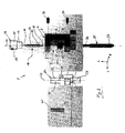
Calatzis et al. (US 5,777,215 ) describe a measuring illustrated inFIG. 1 which is known under the term thromboelastometry. Contrary to the modifications mentioned above, thromboelastometry is based on acup 43 fixed in acup holder 48 while aprobe element 42 is actively rotated. For this purpose theprobe element 42 is attached to a coupling shaft 35' which is suspended by a ball bearing 49 in abase plate 39 and has adrive element 32 connected to it. An oscillating motion perpendicular to the drawing plane induced at the opposite end of thedrive element 32 is transformed into a periodically rotation of the coupling shaft 35' and the connectedcup 43 around arotation axis 20 by about 5° in each direction. As thesample liquid 44 begins to coagulate the motion amplitude of the coupling shaft 35' which is detected by e.g. the deflection of a light beam from detectingmeans 41 and a detectingelement 31, e.g. a mirror, starts to decrease. - During coagulation the fibrin backbone creates a mechanical elastic linkage between the surfaces of the blood-containing
cup 43 and theprobe element 42 plunged therein. A proceeding coagulation process induced by adding one or more activating factor(s) can thus be observed. In this way, various deficiencies of a patient's haemostatic status can be revealed and can be interpreted for proper medical intervention. - A general advantage of viscoelastometric, e.g. thromboelastometric, techniques compared to other laboratory methods in this field therefore is that the coagulation process and the change of mechanical properties of the sample are monitored as a whole. This means that thromboelastometry does not only indicate if all components of the coagulation pathways are available in sufficient amounts but also if each component works properly.
- Compared with the device mentioned above using a torsion wire thromboelastometry as shown in
FIG. 1 has the advantage that a ball bearing provides a certain stability of the measuring device, e.g. the measuring device can be configured as a transportable device and used under POC (point of care) conditions. - It is a problem underlying the presented invention to provide an improved measuring unit for measuring characteristics of a sample liquid, in particular viscoelastic characteristics of a blood sample.
- Directly connected to this invention is the problem to provide a corresponding improved measuring system for measuring viscoelastic characteristics of a sample liquid, in particular the coagulation characteristics of a blood sample liquid. These problems are solved by the subject-matter of the independent claims. Preferred embodiments are set forth in the dependent claims.
- In a first aspect, the present invention provides measuring unit for measuring characteristics of a sample liquid, in particular viscoelastic characteristics of a blood sample, comprising a support member having at least one upper bearing arm with an upper bearing unit, at least one lower bearing arm with a lower bearing unit and a base for being attachable to a respective measuring system; a shaft having shaft toes and being rotatably supported about a rotation axis by said upper bearing unit and said lower bearing unit, wherein said upper bearing unit, said lower bearing unit and said shaft toes form toe bearings, respectively; an interface member having a detecting element and a drive element, said interface member being fixed on said shaft and being connected to a coupling shaft with a probe connector section for measuring characteristics of said sample liquid; wherein said interface member and the coupling shaft are coaxially aligned with said shaft.
- In a second aspect, the present invention provides a measuring system for measuring characteristics of a sample liquid, in particular viscoelastic characteristics of a blood sample, comprising at least one measuring unit according to the invention.
- Toe bearings have clearances and friction losses which are decreased in relation to ball bearings. In particular it is advantageous that toe bearings have smaller clearances regarding tilting as well. The measuring device according to the invention also has the advantage to provide a unit which does not need a basement being aligned horizontally with high precision. Thus it is highly suitable for use in POC conditions and the like. Moreover the measuring unit according to the invention is more unsusceptible in case of vibrations than that one of the state of the art. Another advantage is the miniaturized shape of toe bearings.
- The support member forms a structural rigid component of the measuring unit and supports the shaft by the toe bearings. The shaft is coupled to a coupling shaft by an interface member being a component with several functions.
- Said upper bearing unit and said lower bearing unit are removable inserts each being fixed in said respective bearing arm of said support member. Thus it is possible to remove the bearing units together with the shaft in case of maintenance without changing the support member.
- Said lower bearing unit is a thrust bearing and said upper bearing unit is a moveable bearing. The moveable bearing is configured to be adjustable by adjusting means to achieve optimal friction and clearances.
- The bearing units are equipped with bearing plates made of e.g. kind of jewel, e.g. sapphire or/and ceramic.
- The interface member comprises an upper connector section connected to said shaft. This forms a simple connection to the shaft.
- Furthermore said interface member has a frame having an opening for a passage of said lower bearing arm of said support member, which allows for a compact assembly of the measuring unit and a connection to the coupling shaft. Moreover a lower connector section for a connection to said coupling shaft forms another portion of the interface member.
- Eventually the interface member has a front for securing that said detecting element thereon; and moreover a receptacle for securing that said drive element therein.
- The interface member further comprises a fixing unit for fixing said interface member to said shaft. It is preferred that said fixing unit is at least one screw to achieve a simple fixing.
- In an alternative embodiment said fixing unit is formed having clip means cooperating with corresponding clip means of said shaft.
- It is preferred that said lower connector section is formed having clip means cooperating with corresponding clip means of an interface section of said coupling shaft for easy and fast connection without any tool.
- It is also preferred that said probe connector section of said coupling shaft is formed having clip means cooperating with corresponding clip means of a probe element being detachably fixed onto said probe connector section. Thus an easy assembly and disassembly of different probe elements can be done.
- In another preferred embodiment said detecting element can be a mirror.
- When, in case of inserting the coupling shaft and/or a probe element onto the coupling shaft, an axial force can be exerted on the shaft and the interface member and cause an axial movement of the shaft in direction to the upper movable bearing. To limit said axial movement of the shaft and the interface member and a possible damage of the upper movable bearing the measuring unit can comprise axial stop means. Said stop means can be formed e.g. by a shoulder of the interface member or/and a shoulder of the shaft, said shoulder pointing to the upper bearing arm and co-operating with a corresponding shoulder of the upper bearing arm and/or the upper bearing unit.
- In another embodiment at least one of said upper bearing unit and said lower bearing unit can comprises at least one bearing cover plate. Said bearing cover plate serves as a sealing and/or as a centre means for the shaft.
- And in another embodiment it is preferred that the drive element is a spring wire.
- Further features and advantages of the present invention will be evident from a description of embodiments with reference to the figures.
- The figures are showing the following:
-
FIG. 1 is a schematic drawing of an example of thromboelastometry according to the state of the art. -
FIG. 2 is a perspective exploded view of an exemplary embodiment of a measuring unit according to the invention. -
FIG. 3 is a schematic view along y-direction of a sectional view along arotation axis 20 of the assembled measuring unit ofFIG. 1 -
FIG. 4 is a perspective view of an exemplary embodiment of a measuring device according to the invention. -
FIG. 5 is a top view of the measuring device ofFIG. 4 . -
FIG. 6 is a view along y-direction of the measuring device ofFIG. 4 . -
FIG. 7 is a perspective view in x-direction of the measuring device ofFIG. 4 . - Parts and components having same functions are depicted with same references. Coordinate systems indicating x-, y- and z-direction in the figures allow for better orientation.
- An exemplary embodiment of a measuring
unit 1 according to the invention will now be described with regard toFIG. 2 and toFIG. 3 . -
FIG. 2 is a perspective exploded view of an exemplary embodiment of the measuringunit 1 according to the invention andFIG. 3 is a schematic view along y-direction of a sectional view along arotation axis 20 of the assembled measuringunit 1 ofFIG. 1 . - The measuring unit comprises a
support member 2 with abody 6 extending in z-direction. Thebody 6 connects anupper bearing arm 3 and alower bearing arm 4. The bearingarms Body 6 and said bearingarms arms - The
body 6 and thelower bearing arm 4 are fixed onto abase 5 extending in x-direction. Thebase 5 comprises fixing holes (seeFIG. 4 for mounting elements 38). - The
upper bearing arm 3 is formed with a through hole for anupper bearing unit 14 and thelower bearing arm 4 has a through hole for alower bearing unit 21, the through holes being aligned along arotation axis 20. - The
upper bearing unit 14 and thelower bearing unit 21 are formed as inserts to be inserted into said through holes. An upper fixing passage 8 extending from the side of thebody 6 in theupper bearing arm 3 in y-direction allows for fixing the insertedupper bearing unit 14 by a fixingelement 34, e.g. a screw. The insertedlower bearing unit 21 can be fixed similarly by a fixingelement 34 via a lower fixing passage 9 extending in thelower bearing arm 4. - A
shaft 10 with a shaft body 13 having anupper shaft toe 11 and alower shaft toe 12 is provided to be supported by the bearingunits units shaft 10 having saidupper shaft toe 11 and saidlower shaft toe 12 to form a toe bearing, respectively. Agroove 51 for acirclip 50 is formed in the shaft body 13. - The
upper bearing unit 14 comprises a fixingsection 15 and abearing section 16. As can be seen fromFIG. 3 thebearing section 16 is inserted into a through hole of theupper bearing arm 3. Theupper bearing unit 14 is designed as a movable bearing with a movable bearing plate 46, e.g. made of a kind of jewel or ceramic, arranged in a through hole of the bearingunit 14. Theupper shaft toe 11 of theshaft 10 rests on the movable bearing plate 46. The movable bearing plate 46 is movable along the rotation axis, i.e. in z-direction. Aspring 45 is arranged in the fixingsection 15 and can be adjusted by adjustingmeans 17, e.g. a screw, the adjusting means 17 being fixable by a fixing means 18, e.g. a screw through a fixingpassage 19 in the fixingsection 15. - The
lower bearing unit 21 comprises acollar 22 and abearing section 23. The bearingsection 23 is inserted into a through hole of thelower bearing arm 4, wherein thecollar 22 rests on thelower bearing arm 4. Athrust bearing plate 47 is arranged within a through hole of thelower bearing unit 21 and fixed therein. Thetrust bearing plate 47 is made of the material as the movable bearing plate, wherein thelower shaft toe 12 of theshaft 10 rests on thethrust bearing plate 47. - A pretension of the bearing
units shaft 10 can be adjusted by the adjusting means 17. - The measuring
unit 1 further comprises aninterface member 24 having anupper connector section 25, aframe 26 and alower connector section 27. Anopening 28 is formed in the frame to form a passage having a cross-section greater than the cross-section of the lower bearing arm 4 (see alsoFIG. 3 ). - The
upper connector section 25 is designed with a bore to be connected to theshaft 10 as can be seen fromFIG. 3 , wherein theshaft 10 is fixed by a fixingunit 29, e.g. a screw, to connect theinterface member 24 to theshaft 10. - The
lower connector section 27 is also provided with a bore to be connected to acoupling shaft 35. To this end thecoupling shaft 35 is formed with aninterface section 36 which is preferably designed as a clip means. Other fixing means can be possible. Thecoupling shaft 35 further comprises aprobe connector section 37 which is provided to be connected to a probe element 42 (seeFIG. 1 ). - Furthermore the
interface member 24 has a front 30 on which a detectingelement 31, e.g. a mirror (see alsoFIG. 1 andFIG. 2 ), is fixed, e.g. by glue. Theinterface member 24 also comprises a receptacle 33 on the side of the front at the lower portion of theframe 26. Adrive element 32, e.g. a spring wire, as already shown inFIG. 1 can be inserted into this receptacle 33. - In this example the
upper bearing unit 14 and thelower bearing unit 21 are equipped with bearingcover plates 52. Said bearingcover plates 52 are disc-shaped and inserted into the through holes of the bearingunits shaft 10 which extends through passage holes of thebearing cover plates 52. These passage holes have an inner diameter which is a little bit greater than that of the outer diameter of the corresponding shaft portion. So thebearing cover plates 52 provide a certain sealing function. On the other hand thebearing cover plates 52 can centre theshaft 10. In use there is no friction between the bearingcover plates 52 and the corresponding shaft portions. In the example ofFIG. 3 the bearingcover plate 52 of theupper bearing unit 14 is inserted into the lowest part of thebearing section 16 and co-operates with a cylindrical portion of theupper shaft toe 11 of theshaft 10. The bearingcover plate 52 of thelower bearing unit 21 is inserted into the upper part of thecollar 22 and co-operates with a cylindrical portion of the shaft body 13 of theshaft 10. - An assembly of the measuring
unit 1 can be done as following to achieve the assembled unit (seeFIG. 2 and3 ). - First the
lower bearing unit 21 is inserted into thelower bearing arm 4 and fixed as mentioned above. Then theinterface member 24 is inserted into the recess 7 betweenupper bearing arm 3 andlower bearing arm 4 in such a way that thelower bearing 4 extends and protrudes through theopening 28 of theframe 26 of theinterface member 24. Theinterface member 24 should be aligned with its bores to therotation axis 20. Now theshaft 10 is inserted along therotation axis 20 through the through hole in theupper bearing arm 3, through the bore of theupper connector section 25 of theinterface member 24 into thelower bearing unit 21 so that thelower shaft toe 12 rests on thethrust plate 47 of the lower bearing unit. - Now the
upper bearing unit 14 is inserted into the through hole of theupper bearing arm 3 and fixed as mentioned above, the movable bearing plate 46 resting on theupper shaft toe 11. Then the adjusting means 17 can be adjusted for a predefined pretension now or later. - The
interface member 24 is shifted upwards on the shaft body 13 until thegroove 51 can be fitted with acirclip 50. Then theinterface member 24 is shifted downwards to rest on thecirclip 50 to maintain a predefined axial position along therotation axis 20. Now theinterface member 24 can be fixed on the shaft body 13 by said fixingunit 29. -
Thrust plate 47 and movable plate 46 comprise a dimple, respectively. The dimple will align theshaft 10 together with theinterface member 24 and thecoupling shaft 35. - Finally the
coupling shaft 35, the detectingelement 31 and thedrive element 32 can be connected to theinterface member 24. - When, in case of inserting the
coupling shaft 35 and/or a probe element 42 (seeFIG. 1 ) onto thecoupling shaft 35, an axial force can be exerted via theinterface member 24 on theshaft 10 and cause an axial movement of theshaft 10 in direction of therotation axis 20 to the uppermovable bearing 14. To limit said axial movement of theshaft 10 and theinterface member 24 and a possible damage of the uppermovable bearing 14 the measuringunit 1 can comprise axial stop means. Said stop means can be formed in the shown embodiment e.g. by an upper shoulder of theinterface member 24 or/and a shoulder of theshaft 10, said shoulder pointing to theupper bearing arm 3 and co-operating with a corresponding shoulder of theupper bearing arm 3 and/or theupper bearing unit 14. - The assembled measuring
unit 1 is shown inFIG. 3 and can be mounted on abase plate 39 of a measuringdevice 40 as shown inFIG. 4 , which is a perspective view of an exemplary embodiment of a measuringdevice 40 according to the invention. - In the shown embodiment the measuring
device 40 comprises four measuringunits 1. The measuringunits 1 are fixed on thebase plate 39 by mounting elements, e.g. screws or clip fixing means, thecoupling shafts 35 extending through corresponding openings in thebase plate 39. Thedrive elements 32 extend in y-direction and can be driven by a not shown driving device to oscillate therespective interface members 24 with the thereto connected respective coupling shafts 35 (and corresponding parts as mentioned above) around therespective rotation axis 20. -
FIG. 5 is a top view of the measuringdevice 40 ofFIG. 4 . Here it is shown that thedrive elements 32 and theconnected interface members 24 are arranged in a specific angle to the y-direction. -
FIG. 6 is a view along y-direction of the measuring device ofFIG. 4 , wherein the detectingelements 31 can be seen from a front view. - Finally
FIG. 7 is a perspective view in x-direction of the measuringdevice 40 ofFIG. 4 . -
- 1
- Measuring unit
- 2
- Support member
- 3
- Upper bearing arm
- 4
- Lower bearing arm
- 5
- Base
- 6
- Body
- 7
- Recess
- 8
- Upper fixing passage
- 9
- Lower fixing passage
- 10
- Shaft
- 11
- Upper shaft toe
- 12
- Lower shaft toe
- 13
- Shaft body
- 14
- Upper bearing unit
- 15
- Fixing section
- 16
- Bearing section
- 17
- Adjusting means
- 18
- Fixing means
- 19
- Fixing passage
- 20
- Rotation axis
- 21
- Lower bearing unit
- 22
- Collar
- 23
- Bearing section
- 24
- Interface member
- 25
- Upper connector section
- 26
- Frame
- 27
- Lower connector section
- 28
- Opening
- 29
- Fixing unit
- 30
- Front
- 31
- Detecting element
- 32
- Drive element
- 33
- Receptacle
- 34
- Fixing element
- 35, 35'
- Coupling shaft
- 36
- Interface section
- 37
- Probe connector section
- 38
- Mounting element
- 39
- Base plate
- 40
- Measuring device
- 41
- Detecting means
- 42
- Probe element
- 43
- Cup
- 44
- Sample liquid
- 45
- Spring
- 46
- Movable bearing plate
- 47
- Thrust bearing plate
- 48
- Cup holder
- 49
- Ball bearing
- 50
- Groove
- 51
- Circlip
- 52
- Bearing cover plate
Claims (16)
- A measuring unit (1) for measuring characteristics of a sample liquid (44), in particular viscoelastic characteristics of a blood sample, comprising
a support member (2) having at least one upper bearing arm (3) with an upper bearing unit (14), at least one lower bearing arm (4) with a lower bearing unit (21) and a base (5) for being attachable to a respective measuring system (40);
a shaft (10) having shaft toes (11, 12) and being rotatably supported about a rotation axis (20) by said upper bearing unit (14) and said lower bearing unit (21), wherein said upper bearing unit (14), said lower bearing unit (21) and said shaft toes (11, 12) form toe bearings, respectively;
an interface member (24) having a detecting element (31) and a drive element (32), said interface member (24) being fixed on said shaft (10) and being connected to a coupling shaft (35) with a probe connector section (37) for measuring characteristics of said sample liquid (44);
wherein said interface member (24) and the coupling shaft (35) are coaxially aligned with said shaft (10). - The measuring unit (1) according to claim 1, wherein said upper bearing unit (14) and said lower bearing unit (21) are removable inserts each being fixed in said respective bearing arm (3, 4).
- The measuring unit (1) according to claim 1 or 2, wherein said lower bearing unit (21) is a thrust bearing and said upper bearing unit (14) is a moveable bearing being adjustable by adjusting means (17).
- The measuring unit (1) according to at least one of the preceding claims, wherein said upper bearing unit (14) and said lower bearing unit (21) comprise bearing plates (46, 47) made of a kind of jewel and/or ceramic.
- The measuring unit (1) according to at least one of the preceding claims, wherein said interface member (24) comprises:an upper connector section (25) connected to said shaft (10);a frame (26) having an opening (28) for a passage of said lower bearing arm (4) of said support member (2);a lower connector section (27) connected to said coupling shaft (35);a front (30) for securing that said detecting element (31) thereon; anda receptacle (33) for securing that said drive element (32) therein.
- The measuring unit (1) according to claim 5, wherein said interface member (24) further comprises a fixing unit (29) for fixing said interface member (24) to said shaft (10).
- The measuring unit (1) according to claim 6, wherein said fixing unit (29) is at least one screw.
- The measuring unit (1) according to claim 6, wherein said fixing unit (29) is formed having clip means cooperating with corresponding clip means of said shaft (10).
- The measuring unit (1) according to at least one of the claims 5 to 8, wherein said lower connector section (27) is formed having clip means cooperating with corresponding clip means of an interface section (36) of said coupling shaft (35).
- The measuring unit (1) according to at least one of the preceding claims, wherein said probe connector section (37) of said coupling shaft (35) is formed having clip means cooperating with corresponding clip means of a probe element being detachably fixed onto said probe connector section (37).
- The measuring unit (1) according to at least one of the preceding claims, wherein said detecting element (31) is a mirror.
- The measuring unit (1) according to at least one of the preceding claims, wherein the drive element (32) is a spring wire.
- The measuring unit (1) according to at least one of the preceding claims, comprising axial stop means to limit an axial movement of the shaft (10) and the interface member (24).
- The measuring unit (1) according to claim 13, wherein the axial stop means are formed by a shoulder of the interface member (24) or/and a shoulder of the shaft (10), said shoulder pointing to the upper bearing arm (3) and co-operating with a corresponding shoulder of the upper bearing arm (3) and/or the upper bearing unit (14).
- The measuring unit (1) according to at least one of the preceding claims, wherein at least one of said upper bearing unit (14) and said lower bearing unit (21) comprises at least one bearing cover plate (52).
- Measuring system (40) for measuring characteristics of a sample liquid, in particular viscoelastic characteristics of a blood sample, comprising at least one measuring unit (1) according to at least one of the preceding claims.
Priority Applications (11)
| Application Number | Priority Date | Filing Date | Title |
|---|---|---|---|
| DK09150740.0T DK2208996T3 (en) | 2009-01-16 | 2009-01-16 | Unit of measurement for measuring characteristic features of a test liquid, especially viscoelastic properties of a blood sample |
| EP09150740A EP2208996B1 (en) | 2009-01-16 | 2009-01-16 | A measuring unit for measuring characteristics of a sample liquid, in particular viscoelastic characteristics of a blood sample |
| ES09150740T ES2350718T3 (en) | 2009-01-16 | 2009-01-16 | UNIT OF MEASUREMENT TO MEASURE CHARACTERISTICS OF A SAMPLE LIQUID, IN PARTICULATE THE VISCOELASTIC PROPERTIES OF A BLOOD SAMPLE. |
| AT09150740T ATE479893T1 (en) | 2009-01-16 | 2009-01-16 | MEASURING UNIT FOR MEASURING THE PROPERTIES OF A SAMPLE LIQUID, IN PARTICULAR THE VISCOELASTIC PROPERTIES OF A BLOOD SAMPLE |
| DE602009000162T DE602009000162D1 (en) | 2009-01-16 | 2009-01-16 | Measuring unit for measuring the properties of a sample liquid, in particular the viscoelastic properties of a blood sample |
| RU2011122394/15A RU2519749C2 (en) | 2009-01-16 | 2010-01-15 | Measuring device for measurement of characteristics of liquid sample, and namely viscoelastic characteristics of blood sample |
| PCT/EP2010/050454 WO2010081876A1 (en) | 2009-01-16 | 2010-01-15 | A measuring unit for measuring characteristics of a sample liquid, in particular viscoelastic characteristics of a blood sample |
| CN2010800043295A CN102272594B (en) | 2009-01-16 | 2010-01-15 | A measuring unit for measuring characteristics of a sample liquid, in particular viscoelastic characteristics of a blood sample |
| BRPI1006810A BRPI1006810A2 (en) | 2009-01-16 | 2010-01-15 | unit of measurement for measuring characteristics of a sample fluid, especially the viscoelastic characteristics of a blood sample |
| KR1020117017438A KR20110125633A (en) | 2009-01-16 | 2010-01-15 | Measurement unit for measuring the properties of the sample liquid, especially the viscoelastic properties of the blood sample |
| JP2011545745A JP5450653B2 (en) | 2009-01-16 | 2010-01-15 | Measuring unit for measuring the properties of sample liquids, especially viscoelastic properties of blood samples |
Applications Claiming Priority (1)
| Application Number | Priority Date | Filing Date | Title |
|---|---|---|---|
| EP09150740A EP2208996B1 (en) | 2009-01-16 | 2009-01-16 | A measuring unit for measuring characteristics of a sample liquid, in particular viscoelastic characteristics of a blood sample |
Publications (2)
| Publication Number | Publication Date |
|---|---|
| EP2208996A1 EP2208996A1 (en) | 2010-07-21 |
| EP2208996B1 true EP2208996B1 (en) | 2010-09-01 |
Family
ID=40780275
Family Applications (1)
| Application Number | Title | Priority Date | Filing Date |
|---|---|---|---|
| EP09150740A Not-in-force EP2208996B1 (en) | 2009-01-16 | 2009-01-16 | A measuring unit for measuring characteristics of a sample liquid, in particular viscoelastic characteristics of a blood sample |
Country Status (10)
| Country | Link |
|---|---|
| EP (1) | EP2208996B1 (en) |
| JP (1) | JP5450653B2 (en) |
| KR (1) | KR20110125633A (en) |
| CN (1) | CN102272594B (en) |
| AT (1) | ATE479893T1 (en) |
| BR (1) | BRPI1006810A2 (en) |
| DE (1) | DE602009000162D1 (en) |
| DK (1) | DK2208996T3 (en) |
| ES (1) | ES2350718T3 (en) |
| RU (1) | RU2519749C2 (en) |
Cited By (1)
| Publication number | Priority date | Publication date | Assignee | Title |
|---|---|---|---|---|
| US10295554B2 (en) | 2015-06-29 | 2019-05-21 | C A Casyso Gmbh | Blood testing system and method |
Families Citing this family (17)
| Publication number | Priority date | Publication date | Assignee | Title |
|---|---|---|---|---|
| US8448499B2 (en) | 2008-12-23 | 2013-05-28 | C A Casyso Ag | Cartridge device for a measuring system for measuring viscoelastic characteristics of a sample liquid, a corresponding measuring system, and a corresponding method |
| US9897618B2 (en) | 2014-09-29 | 2018-02-20 | C A Casyso Gmbh | Blood testing system |
| US10288630B2 (en) | 2014-09-29 | 2019-05-14 | C A Casyso Gmbh | Blood testing system and method |
| US10175225B2 (en) | 2014-09-29 | 2019-01-08 | C A Casyso Ag | Blood testing system and method |
| US10539579B2 (en) | 2014-09-29 | 2020-01-21 | C A Casyso Gmbh | Blood testing system and method |
| US10816559B2 (en) | 2014-09-29 | 2020-10-27 | Ca Casyso Ag | Blood testing system and method |
| JP6175601B2 (en) * | 2015-06-30 | 2017-08-09 | ツェー アー カズィゾ アーゲーC A Casyso Ag | Blood test system and method |
| JP6924257B2 (en) | 2016-04-29 | 2021-08-25 | ネオテック バイオサイエンス カンパニー リミテッド | A lid removal device and a thromboelast graph equipped with the device |
| WO2017186186A1 (en) | 2016-04-29 | 2017-11-02 | 诺泰科生物科技(苏州)有限公司 | Thrombelastograph analyser and method for detecting rotation angle of rotating shaft |
| US10761082B2 (en) | 2016-04-29 | 2020-09-01 | Neotek Bioscience Co., Ltd. | Bracket, thrombelastography device, and support system |
| US10801939B2 (en) * | 2016-04-29 | 2020-10-13 | Neotek Bioscience Co., Ltd. | Apparatus for measuring blood coagulation data and use method thereof, connection member and support |
| CN106438668A (en) * | 2016-08-30 | 2017-02-22 | 诺泰科生物科技(苏州)有限公司 | Connection assembly, support, thrombus elastometer and use method |
| CN109642909B (en) * | 2016-08-29 | 2022-06-03 | 藤森工业株式会社 | Blood coagulation test device and blood coagulation test method |
| US10473674B2 (en) | 2016-08-31 | 2019-11-12 | C A Casyso Gmbh | Controlled blood delivery to mixing chamber of a blood testing cartridge |
| CN113776989A (en) | 2017-01-26 | 2021-12-10 | 埃尼科尔股份有限公司 | Apparatus and method for measuring viscoelastic changes of a sample |
| US10843185B2 (en) | 2017-07-12 | 2020-11-24 | Ca Casyso Gmbh | Autoplatelet cartridge device |
| CN113865846B (en) * | 2021-09-26 | 2024-03-19 | 恪宁科技(上海)有限公司 | A device and method for detecting the stiffness coefficient of thromboelastography draping wires |
Family Cites Families (9)
| Publication number | Priority date | Publication date | Assignee | Title |
|---|---|---|---|---|
| IT1076740B (en) * | 1977-04-28 | 1985-04-27 | E L V I Spa | BLOOD ELASTICITY PARAMETER DETERMINATION EQUIPMENT |
| SU1195247A1 (en) * | 1983-10-21 | 1985-11-30 | Всесоюзный Ордена Трудового Красного Знамени Научно-Исследовательский Институт Общей И Судебной Психиатрии Им.В.П.Сербского | Arrangement for agitation of biological liquids |
| US5287732A (en) * | 1990-10-03 | 1994-02-22 | Toki Sangyo Co., Ltd. | Rotary viscosimeter |
| FR2678381B1 (en) * | 1991-06-27 | 1994-10-07 | Total Sa | CONSISTOMETER. |
| US5447440A (en) * | 1993-10-28 | 1995-09-05 | I-Stat Corporation | Apparatus for assaying viscosity changes in fluid samples and method of conducting same |
| EP0734524B1 (en) | 1994-10-19 | 1997-05-21 | Alexander Calatzis | Device for measuring the coagulation properties of test liquids |
| JP5090908B2 (en) * | 2004-07-12 | 2012-12-05 | ブイディジイ−フォン・デア・ゴルツ・ゲーエムベーハー | Apparatus and method for automatically examining blood samples |
| CN1712963A (en) * | 2005-07-08 | 2005-12-28 | 天津米克莱特生物技术有限公司 | Device and method for measuring blood viscosity by dynamic optical tweezers technology |
| CN201000452Y (en) * | 2006-03-07 | 2008-01-02 | 北京赛科希德科技发展有限公司 | Conical plate type velocity attenuation blood viscosity measuring apparatus |
-
2009
- 2009-01-16 DK DK09150740.0T patent/DK2208996T3/en active
- 2009-01-16 EP EP09150740A patent/EP2208996B1/en not_active Not-in-force
- 2009-01-16 DE DE602009000162T patent/DE602009000162D1/en active Active
- 2009-01-16 ES ES09150740T patent/ES2350718T3/en active Active
- 2009-01-16 AT AT09150740T patent/ATE479893T1/en active
-
2010
- 2010-01-15 KR KR1020117017438A patent/KR20110125633A/en not_active Abandoned
- 2010-01-15 CN CN2010800043295A patent/CN102272594B/en not_active Expired - Fee Related
- 2010-01-15 RU RU2011122394/15A patent/RU2519749C2/en not_active IP Right Cessation
- 2010-01-15 BR BRPI1006810A patent/BRPI1006810A2/en not_active IP Right Cessation
- 2010-01-15 JP JP2011545745A patent/JP5450653B2/en active Active
Cited By (2)
| Publication number | Priority date | Publication date | Assignee | Title |
|---|---|---|---|---|
| US10295554B2 (en) | 2015-06-29 | 2019-05-21 | C A Casyso Gmbh | Blood testing system and method |
| US11085938B2 (en) | 2015-06-29 | 2021-08-10 | C A Casyso Gmbh | Thromboelastometry blood testing system and accuracy control methods |
Also Published As
| Publication number | Publication date |
|---|---|
| ES2350718T3 (en) | 2011-01-26 |
| BRPI1006810A2 (en) | 2017-05-30 |
| JP2012515340A (en) | 2012-07-05 |
| DE602009000162D1 (en) | 2010-10-14 |
| EP2208996A1 (en) | 2010-07-21 |
| RU2519749C2 (en) | 2014-06-20 |
| KR20110125633A (en) | 2011-11-21 |
| ATE479893T1 (en) | 2010-09-15 |
| RU2011122394A (en) | 2013-02-27 |
| DK2208996T3 (en) | 2010-12-13 |
| JP5450653B2 (en) | 2014-03-26 |
| CN102272594B (en) | 2013-12-11 |
| CN102272594A (en) | 2011-12-07 |
Similar Documents
| Publication | Publication Date | Title |
|---|---|---|
| US8383045B2 (en) | Measuring unit for measuring characteristics of a sample liquid, in particular viscoelastic characteristics of a blood sample | |
| EP2208996A1 (en) | A measuring unit for measuring characteristics of a sample liquid, in particular viscoelastic characteristics of a blood sample | |
| US12105103B2 (en) | Cartridge device for a measuring system for measuring viscoelastic characteristics of a sample liquid, a corresponding measuring system, and a corresponding method | |
| JP5655091B2 (en) | Portable blood coagulation monitoring device and evaluation method of blood coagulation reaction | |
| EP2154511A2 (en) | Apparatus and method for measuring the coagulation characteristics of a test liquid | |
| EP3734274B1 (en) | System for measuring viscoelastic properties of blood | |
| US11768210B2 (en) | Portable coagulation monitoring devices, systems, and methods | |
| CN104981477A (en) | Device and method for performing blood thromboelastographic assays by magnetic sensing | |
| JP6503605B2 (en) | Portable device, system and method for blood coagulation monitoring | |
| WO2010081876A1 (en) | A measuring unit for measuring characteristics of a sample liquid, in particular viscoelastic characteristics of a blood sample | |
| US12392768B2 (en) | Methods for determining blood gas or metabolic parameters | |
| CN115144575B (en) | A test probe for thromboelastography | |
| CN115144574A (en) | A detection device for thromboelastometry | |
| US12405280B2 (en) | Portable coagulation monitoring devices, systems, and methods |
Legal Events
| Date | Code | Title | Description |
|---|---|---|---|
| GRAP | Despatch of communication of intention to grant a patent |
Free format text: ORIGINAL CODE: EPIDOSNIGR1 |
|
| GRAS | Grant fee paid |
Free format text: ORIGINAL CODE: EPIDOSNIGR3 |
|
| PUAI | Public reference made under article 153(3) epc to a published international application that has entered the european phase |
Free format text: ORIGINAL CODE: 0009012 |
|
| 17P | Request for examination filed |
Effective date: 20090727 |
|
| AK | Designated contracting states |
Kind code of ref document: A1 Designated state(s): AT BE BG CH CY CZ DE DK EE ES FI FR GB GR HR HU IE IS IT LI LT LU LV MC MK MT NL NO PL PT RO SE SI SK TR |
|
| GRAA | (expected) grant |
Free format text: ORIGINAL CODE: 0009210 |
|
| AK | Designated contracting states |
Kind code of ref document: B1 Designated state(s): AT BE BG CH CY CZ DE DK EE ES FI FR GB GR HR HU IE IS IT LI LT LU LV MC MK MT NL NO PL PT RO SE SI SK TR |
|
| REG | Reference to a national code |
Ref country code: GB Ref legal event code: FG4D |
|
| REG | Reference to a national code |
Ref country code: CH Ref legal event code: EP |
|
| REG | Reference to a national code |
Ref country code: IE Ref legal event code: FG4D |
|
| REF | Corresponds to: |
Ref document number: 602009000162 Country of ref document: DE Date of ref document: 20101014 Kind code of ref document: P |
|
| REG | Reference to a national code |
Ref country code: CH Ref legal event code: NV Representative=s name: HEPP WENGER RYFFEL AG |
|
| REG | Reference to a national code |
Ref country code: DK Ref legal event code: T3 |
|
| REG | Reference to a national code |
Ref country code: NL Ref legal event code: T3 |
|
| REG | Reference to a national code |
Ref country code: SE Ref legal event code: TRGR |
|
| REG | Reference to a national code |
Ref country code: ES Ref legal event code: FG2A Effective date: 20110114 |
|
| PG25 | Lapsed in a contracting state [announced via postgrant information from national office to epo] |
Ref country code: LT Free format text: LAPSE BECAUSE OF FAILURE TO SUBMIT A TRANSLATION OF THE DESCRIPTION OR TO PAY THE FEE WITHIN THE PRESCRIBED TIME-LIMIT Effective date: 20100901 Ref country code: FI Free format text: LAPSE BECAUSE OF FAILURE TO SUBMIT A TRANSLATION OF THE DESCRIPTION OR TO PAY THE FEE WITHIN THE PRESCRIBED TIME-LIMIT Effective date: 20100901 |
|
| REG | Reference to a national code |
Ref country code: NO Ref legal event code: T2 Effective date: 20100901 |
|
| LTIE | Lt: invalidation of european patent or patent extension |
Effective date: 20100901 |
|
| PG25 | Lapsed in a contracting state [announced via postgrant information from national office to epo] |
Ref country code: SI Free format text: LAPSE BECAUSE OF FAILURE TO SUBMIT A TRANSLATION OF THE DESCRIPTION OR TO PAY THE FEE WITHIN THE PRESCRIBED TIME-LIMIT Effective date: 20100901 Ref country code: CY Free format text: LAPSE BECAUSE OF FAILURE TO SUBMIT A TRANSLATION OF THE DESCRIPTION OR TO PAY THE FEE WITHIN THE PRESCRIBED TIME-LIMIT Effective date: 20100901 Ref country code: HR Free format text: LAPSE BECAUSE OF FAILURE TO SUBMIT A TRANSLATION OF THE DESCRIPTION OR TO PAY THE FEE WITHIN THE PRESCRIBED TIME-LIMIT Effective date: 20100901 Ref country code: PL Free format text: LAPSE BECAUSE OF FAILURE TO SUBMIT A TRANSLATION OF THE DESCRIPTION OR TO PAY THE FEE WITHIN THE PRESCRIBED TIME-LIMIT Effective date: 20100901 |
|
| AKX | Designation fees paid |
Designated state(s): AT BE BG CH CY CZ DE DK EE ES FI FR GB GR HR HU IE IS IT LI LT LU LV MC MK MT NL NO PL PT RO SE SI SK TR |
|
| PG25 | Lapsed in a contracting state [announced via postgrant information from national office to epo] |
Ref country code: LV Free format text: LAPSE BECAUSE OF FAILURE TO SUBMIT A TRANSLATION OF THE DESCRIPTION OR TO PAY THE FEE WITHIN THE PRESCRIBED TIME-LIMIT Effective date: 20100901 Ref country code: GR Free format text: LAPSE BECAUSE OF FAILURE TO SUBMIT A TRANSLATION OF THE DESCRIPTION OR TO PAY THE FEE WITHIN THE PRESCRIBED TIME-LIMIT Effective date: 20101202 |
|
| PG25 | Lapsed in a contracting state [announced via postgrant information from national office to epo] |
Ref country code: PT Free format text: LAPSE BECAUSE OF FAILURE TO SUBMIT A TRANSLATION OF THE DESCRIPTION OR TO PAY THE FEE WITHIN THE PRESCRIBED TIME-LIMIT Effective date: 20110103 Ref country code: EE Free format text: LAPSE BECAUSE OF FAILURE TO SUBMIT A TRANSLATION OF THE DESCRIPTION OR TO PAY THE FEE WITHIN THE PRESCRIBED TIME-LIMIT Effective date: 20100901 Ref country code: SK Free format text: LAPSE BECAUSE OF FAILURE TO SUBMIT A TRANSLATION OF THE DESCRIPTION OR TO PAY THE FEE WITHIN THE PRESCRIBED TIME-LIMIT Effective date: 20100901 Ref country code: IS Free format text: LAPSE BECAUSE OF FAILURE TO SUBMIT A TRANSLATION OF THE DESCRIPTION OR TO PAY THE FEE WITHIN THE PRESCRIBED TIME-LIMIT Effective date: 20110101 Ref country code: CZ Free format text: LAPSE BECAUSE OF FAILURE TO SUBMIT A TRANSLATION OF THE DESCRIPTION OR TO PAY THE FEE WITHIN THE PRESCRIBED TIME-LIMIT Effective date: 20100901 |
|
| PLBE | No opposition filed within time limit |
Free format text: ORIGINAL CODE: 0009261 |
|
| STAA | Information on the status of an ep patent application or granted ep patent |
Free format text: STATUS: NO OPPOSITION FILED WITHIN TIME LIMIT |
|
| 26N | No opposition filed |
Effective date: 20110606 |
|
| PG25 | Lapsed in a contracting state [announced via postgrant information from national office to epo] |
Ref country code: MC Free format text: LAPSE BECAUSE OF NON-PAYMENT OF DUE FEES Effective date: 20110131 |
|
| REG | Reference to a national code |
Ref country code: DE Ref legal event code: R097 Ref document number: 602009000162 Country of ref document: DE Effective date: 20110606 |
|
| PG25 | Lapsed in a contracting state [announced via postgrant information from national office to epo] |
Ref country code: MT Free format text: LAPSE BECAUSE OF FAILURE TO SUBMIT A TRANSLATION OF THE DESCRIPTION OR TO PAY THE FEE WITHIN THE PRESCRIBED TIME-LIMIT Effective date: 20100901 |
|
| PGFP | Annual fee paid to national office [announced via postgrant information from national office to epo] |
Ref country code: IE Payment date: 20111114 Year of fee payment: 4 |
|
| PG25 | Lapsed in a contracting state [announced via postgrant information from national office to epo] |
Ref country code: MK Free format text: LAPSE BECAUSE OF FAILURE TO SUBMIT A TRANSLATION OF THE DESCRIPTION OR TO PAY THE FEE WITHIN THE PRESCRIBED TIME-LIMIT Effective date: 20100901 |
|
| PG25 | Lapsed in a contracting state [announced via postgrant information from national office to epo] |
Ref country code: LU Free format text: LAPSE BECAUSE OF NON-PAYMENT OF DUE FEES Effective date: 20110116 |
|
| PG25 | Lapsed in a contracting state [announced via postgrant information from national office to epo] |
Ref country code: BG Free format text: LAPSE BECAUSE OF FAILURE TO SUBMIT A TRANSLATION OF THE DESCRIPTION OR TO PAY THE FEE WITHIN THE PRESCRIBED TIME-LIMIT Effective date: 20101201 Ref country code: TR Free format text: LAPSE BECAUSE OF FAILURE TO SUBMIT A TRANSLATION OF THE DESCRIPTION OR TO PAY THE FEE WITHIN THE PRESCRIBED TIME-LIMIT Effective date: 20100901 |
|
| REG | Reference to a national code |
Ref country code: IE Ref legal event code: MM4A |
|
| PG25 | Lapsed in a contracting state [announced via postgrant information from national office to epo] |
Ref country code: HU Free format text: LAPSE BECAUSE OF FAILURE TO SUBMIT A TRANSLATION OF THE DESCRIPTION OR TO PAY THE FEE WITHIN THE PRESCRIBED TIME-LIMIT Effective date: 20100901 |
|
| PG25 | Lapsed in a contracting state [announced via postgrant information from national office to epo] |
Ref country code: IE Free format text: LAPSE BECAUSE OF NON-PAYMENT OF DUE FEES Effective date: 20130116 |
|
| PG25 | Lapsed in a contracting state [announced via postgrant information from national office to epo] |
Ref country code: RO Free format text: LAPSE BECAUSE OF FAILURE TO SUBMIT A TRANSLATION OF THE DESCRIPTION OR TO PAY THE FEE WITHIN THE PRESCRIBED TIME-LIMIT Effective date: 20100901 |
|
| REG | Reference to a national code |
Ref country code: FR Ref legal event code: PLFP Year of fee payment: 7 |
|
| PGFP | Annual fee paid to national office [announced via postgrant information from national office to epo] |
Ref country code: NL Payment date: 20150129 Year of fee payment: 7 |
|
| PGFP | Annual fee paid to national office [announced via postgrant information from national office to epo] |
Ref country code: DE Payment date: 20150130 Year of fee payment: 7 Ref country code: CH Payment date: 20150121 Year of fee payment: 7 Ref country code: DK Payment date: 20150121 Year of fee payment: 7 Ref country code: IT Payment date: 20150123 Year of fee payment: 7 Ref country code: ES Payment date: 20150128 Year of fee payment: 7 Ref country code: NO Payment date: 20150114 Year of fee payment: 7 |
|
| PGFP | Annual fee paid to national office [announced via postgrant information from national office to epo] |
Ref country code: AT Payment date: 20150122 Year of fee payment: 7 Ref country code: GB Payment date: 20150121 Year of fee payment: 7 Ref country code: SE Payment date: 20150121 Year of fee payment: 7 Ref country code: FR Payment date: 20150122 Year of fee payment: 7 |
|
| PGFP | Annual fee paid to national office [announced via postgrant information from national office to epo] |
Ref country code: BE Payment date: 20150121 Year of fee payment: 7 |
|
| PG25 | Lapsed in a contracting state [announced via postgrant information from national office to epo] |
Ref country code: BE Free format text: LAPSE BECAUSE OF NON-PAYMENT OF DUE FEES Effective date: 20160131 |
|
| REG | Reference to a national code |
Ref country code: DE Ref legal event code: R119 Ref document number: 602009000162 Country of ref document: DE |
|
| REG | Reference to a national code |
Ref country code: NO Ref legal event code: MMEP Ref country code: DK Ref legal event code: EBP Effective date: 20160131 |
|
| REG | Reference to a national code |
Ref country code: CH Ref legal event code: PL |
|
| REG | Reference to a national code |
Ref country code: AT Ref legal event code: MM01 Ref document number: 479893 Country of ref document: AT Kind code of ref document: T Effective date: 20160116 |
|
| GBPC | Gb: european patent ceased through non-payment of renewal fee |
Effective date: 20160116 |
|
| REG | Reference to a national code |
Ref country code: NL Ref legal event code: MM Effective date: 20160201 |
|
| REG | Reference to a national code |
Ref country code: FR Ref legal event code: ST Effective date: 20160930 |
|
| PG25 | Lapsed in a contracting state [announced via postgrant information from national office to epo] |
Ref country code: DE Free format text: LAPSE BECAUSE OF NON-PAYMENT OF DUE FEES Effective date: 20160802 Ref country code: CH Free format text: LAPSE BECAUSE OF NON-PAYMENT OF DUE FEES Effective date: 20160131 Ref country code: GB Free format text: LAPSE BECAUSE OF NON-PAYMENT OF DUE FEES Effective date: 20160116 Ref country code: LI Free format text: LAPSE BECAUSE OF NON-PAYMENT OF DUE FEES Effective date: 20160131 Ref country code: NO Free format text: LAPSE BECAUSE OF NON-PAYMENT OF DUE FEES Effective date: 20160131 |
|
| PG25 | Lapsed in a contracting state [announced via postgrant information from national office to epo] |
Ref country code: SE Free format text: LAPSE BECAUSE OF NON-PAYMENT OF DUE FEES Effective date: 20160117 Ref country code: NL Free format text: LAPSE BECAUSE OF NON-PAYMENT OF DUE FEES Effective date: 20160201 Ref country code: FR Free format text: LAPSE BECAUSE OF NON-PAYMENT OF DUE FEES Effective date: 20160201 Ref country code: AT Free format text: LAPSE BECAUSE OF NON-PAYMENT OF DUE FEES Effective date: 20160116 |
|
| PG25 | Lapsed in a contracting state [announced via postgrant information from national office to epo] |
Ref country code: IT Free format text: LAPSE BECAUSE OF NON-PAYMENT OF DUE FEES Effective date: 20160116 |
|
| PG25 | Lapsed in a contracting state [announced via postgrant information from national office to epo] |
Ref country code: DK Free format text: LAPSE BECAUSE OF NON-PAYMENT OF DUE FEES Effective date: 20160131 |
|
| REG | Reference to a national code |
Ref country code: ES Ref legal event code: FD2A Effective date: 20170227 |
|
| PG25 | Lapsed in a contracting state [announced via postgrant information from national office to epo] |
Ref country code: ES Free format text: LAPSE BECAUSE OF NON-PAYMENT OF DUE FEES Effective date: 20160117 |