EP2208955B1 - Intercalaire d'échange de chaleur pour un dispositif d'échange de chaleur. - Google Patents
Intercalaire d'échange de chaleur pour un dispositif d'échange de chaleur. Download PDFInfo
- Publication number
- EP2208955B1 EP2208955B1 EP10150574.1A EP10150574A EP2208955B1 EP 2208955 B1 EP2208955 B1 EP 2208955B1 EP 10150574 A EP10150574 A EP 10150574A EP 2208955 B1 EP2208955 B1 EP 2208955B1
- Authority
- EP
- European Patent Office
- Prior art keywords
- thickness
- heat exchange
- innerfin
- exchange device
- localized
- Prior art date
- Legal status (The legal status is an assumption and is not a legal conclusion. Google has not performed a legal analysis and makes no representation as to the accuracy of the status listed.)
- Active
Links
- 229910052751 metal Inorganic materials 0.000 claims description 18
- 239000002184 metal Substances 0.000 claims description 18
- 238000005096 rolling process Methods 0.000 claims description 5
- 238000003754 machining Methods 0.000 claims description 3
- 239000012530 fluid Substances 0.000 description 23
- 125000006850 spacer group Chemical group 0.000 description 18
- 239000011229 interlayer Substances 0.000 description 14
- 238000004378 air conditioning Methods 0.000 description 6
- 238000011144 upstream manufacturing Methods 0.000 description 6
- 239000013529 heat transfer fluid Substances 0.000 description 5
- 239000002826 coolant Substances 0.000 description 4
- 230000008719 thickening Effects 0.000 description 3
- CURLTUGMZLYLDI-UHFFFAOYSA-N Carbon dioxide Chemical compound O=C=O CURLTUGMZLYLDI-UHFFFAOYSA-N 0.000 description 2
- 239000012809 cooling fluid Substances 0.000 description 2
- 230000006866 deterioration Effects 0.000 description 2
- 239000011888 foil Substances 0.000 description 2
- 238000010438 heat treatment Methods 0.000 description 2
- 238000012423 maintenance Methods 0.000 description 2
- 238000004519 manufacturing process Methods 0.000 description 2
- 238000005192 partition Methods 0.000 description 2
- 230000009467 reduction Effects 0.000 description 2
- 239000003507 refrigerant Substances 0.000 description 2
- 229910000838 Al alloy Inorganic materials 0.000 description 1
- 229910052782 aluminium Inorganic materials 0.000 description 1
- XAGFODPZIPBFFR-UHFFFAOYSA-N aluminium Chemical compound [Al] XAGFODPZIPBFFR-UHFFFAOYSA-N 0.000 description 1
- 238000005219 brazing Methods 0.000 description 1
- 229910002092 carbon dioxide Inorganic materials 0.000 description 1
- 239000001569 carbon dioxide Substances 0.000 description 1
- 150000001875 compounds Chemical class 0.000 description 1
- 238000005520 cutting process Methods 0.000 description 1
- 230000002950 deficient Effects 0.000 description 1
- 150000002739 metals Chemical class 0.000 description 1
- 230000002093 peripheral effect Effects 0.000 description 1
- 238000009423 ventilation Methods 0.000 description 1
Images


Classifications
-
- F—MECHANICAL ENGINEERING; LIGHTING; HEATING; WEAPONS; BLASTING
- F28—HEAT EXCHANGE IN GENERAL
- F28F—DETAILS OF HEAT-EXCHANGE AND HEAT-TRANSFER APPARATUS, OF GENERAL APPLICATION
- F28F1/00—Tubular elements; Assemblies of tubular elements
- F28F1/02—Tubular elements of cross-section which is non-circular
- F28F1/025—Tubular elements of cross-section which is non-circular with variable shape, e.g. with modified tube ends, with different geometrical features
-
- F—MECHANICAL ENGINEERING; LIGHTING; HEATING; WEAPONS; BLASTING
- F28—HEAT EXCHANGE IN GENERAL
- F28F—DETAILS OF HEAT-EXCHANGE AND HEAT-TRANSFER APPARATUS, OF GENERAL APPLICATION
- F28F1/00—Tubular elements; Assemblies of tubular elements
- F28F1/10—Tubular elements and assemblies thereof with means for increasing heat-transfer area, e.g. with fins, with projections, with recesses
- F28F1/12—Tubular elements and assemblies thereof with means for increasing heat-transfer area, e.g. with fins, with projections, with recesses the means being only outside the tubular element
- F28F1/126—Tubular elements and assemblies thereof with means for increasing heat-transfer area, e.g. with fins, with projections, with recesses the means being only outside the tubular element consisting of zig-zag shaped fins
- F28F1/128—Fins with openings, e.g. louvered fins
-
- F—MECHANICAL ENGINEERING; LIGHTING; HEATING; WEAPONS; BLASTING
- F28—HEAT EXCHANGE IN GENERAL
- F28F—DETAILS OF HEAT-EXCHANGE AND HEAT-TRANSFER APPARATUS, OF GENERAL APPLICATION
- F28F2215/00—Fins
-
- F—MECHANICAL ENGINEERING; LIGHTING; HEATING; WEAPONS; BLASTING
- F28—HEAT EXCHANGE IN GENERAL
- F28F—DETAILS OF HEAT-EXCHANGE AND HEAT-TRANSFER APPARATUS, OF GENERAL APPLICATION
- F28F2225/00—Reinforcing means
- F28F2225/06—Reinforcing means for fins
Definitions
- the invention relates to a heat exchange pad for a heat exchange device according to the preamble of claim 1 to heat exchange devices comprising such spacers.
- JP 2002 147982 discloses such a heat exchange interlayer. It relates more particularly to a heat exchange device, particularly for motor vehicles, comprising a bundle of spaced apart tubes and a plurality of corrugated heat exchange tabs in the form of folded metal strips. so as to form a succession of substantially planar portions each disposed between two tubes and connected in pairs by an angled junction portion of size adapted to the intervals.
- a heat exchange device has the function of allowing the exchange of heat between a fluid circulating inside tubes and an external fluid passing through the heat exchange device. To increase the performance of the heat exchange between the fluid circulating inside the tubes and the external fluid, it is common to provide the heat exchange device with means for increasing the exchange surface between the external fluid and the circulating fluid inside the tubes.
- such a heat exchanger commonly comprises one or more rows of aligned tubes in which circulates a heat transfer fluid. All of these tubes are generally referred to as the beam term.
- Such a heat exchanger serves to allow a heat exchange between the fluid coolant circulating in the tubes, and a fluid traversing externally the heat exchange device.
- the heat exchange device of a plurality of corrugated general heat exchange tabs formed by the succession of substantially flat portions connected two by two by an angled junction portion.
- a corrugated spacer is disposed between two tubes so that a portion of the bent portion is in contact with a tube.
- Such a heat exchange device may for example be integrated with a motor vehicle air conditioning system.
- the external fluid passing through the device is generally air intended to be blown into the passenger compartment of the vehicle, and the coolant a cooling fluid.
- the purpose of heat exchange is to cool the air supply.
- the heat exchange device is then an evaporator.
- the circulation of the fluid, inside the air conditioning circuit, is provided by a compressor, generally driven directly by the engine of the motor vehicle.
- the heat exchange device is made from metals, in particular aluminum.
- metals in particular aluminum.
- the thickness of the metal foils used tends to be less than 70 micrometers for the spacers and less than 270 micrometers for the tubes. Such reductions in thickness have the disadvantageous consequences that the mechanical strength of the heat exchange device is reduced resulting in an increased risk of failure and accelerated deterioration.
- the risk of deterioration is even greater when, in the production phase of the heat exchange device, the bundle of tubes and spacers is put under holding stress in order to ensure good cohesion during the final phase. manufacturing process of brazing the various elements together.
- the bundle of tubes and spacers may be deformed and / or staggered and thus be defective, for example by the creation of leaks, or be of lesser performance, for example by an increase in pressure losses. .
- the object of the invention is therefore to provide a new type of heat exchange device of the type mentioned in the introduction overcoming the aforementioned drawbacks.
- the invention therefore provides a spacer for a heat exchange device according to claim 1.
- the first thickness and the second thickness are such that the second thickness is less than twice the first thickness and the second thickness is greater than or equal to one and a half times the first thickness.
- the second zone defines a localized excess thickness arranged at the ends of the spacer.
- the first zone is obtained by local thinning of the metal strip, produced by machining, rolling, stamping or forming.
- the localized extra thickness of the spacer defines at least one transverse excrescence of a given height, for example equal to the difference between the second thickness and the first thickness.
- the present invention is also specific to a heat exchange device comprising at least one interlayer as defined above.
- the interlayer comprises two localized thicknesses arranged on the same side or on two opposite sides of the insert.
- the exchanger comprises at least one heat exchange tube arranged between at least two localized thicknesses.
- the heat exchange tube comprises at least one localized deformation adapted to cooperate with the localized thickness of the interlayer.
- the figure 1 represents, viewed from the front, a heat exchange device 2.
- the heat exchange device 2 comprises a bundle of tubes 8 spaced apart by a gap 12 in which a corrugated spacer 10 is arranged.
- the corrugated inserts 10 are in the form of a sheet or metal strip 20 folded so as to form a succession of planar portions 22 or substantially planar disposed each between two tubes 8 and connected in pairs by a junction portion 24 bent of dimension adapted to the gaps 12 arranged between two successive tubes 10.
- the heat exchange device 2 also comprises a first collector 4 and a second collector 6 respectively receiving one and the other of the ends of fluid circulation tubes 8, in particular a coolant or heat transfer fluid.
- the tubes 8 are arranged aligned, regularly spaced from each other, and thus form the bundle of tubes 8.
- the first collector 4 is connected to an inlet pipe 14 and the second collector 6 is connected to an outlet pipe 16 respectively connected to an air conditioning circuit in which a fluid circulates, in particular a coolant or heat transfer fluid.
- the fluid coming from an upstream portion of the air conditioning circuit, enters via the inlet pipe 14 into the first tubular collector 4, circulates in the tubes 8 and reaches the second collector 6. From there, the fluid flows through the second collector 6 before exiting via the outlet pipe 16, which is connected to a downstream part of the air conditioning circuit.
- the heat exchange device 2 comprises a single collector having two internal parts separated by an internal partition or made by two chambers. collectors arranged side-by-side so that the inlet pipe 14 and the outlet pipe 16 are respectively disposed in the single collector.
- the bundle of tubes 8 and inserts 10 comprises two end plates 18 contributing to the general maintenance and overall resistance of the heat exchange device 2.
- the present invention also covers heat exchange devices not comprising end plates 18.
- the heat exchange device 2 makes it possible to exchange heat between an external fluid, for example air, passing through the heat exchange device 2 and the fluid circulating inside the tubes 8, for example a refrigerant or heat transfer fluid.
- an external fluid for example air
- the fluid flowing inside the tubes 8 may be a supercritical fluid, in particular carbon dioxide, also known under the name R744, or a subcritical fluid, in particular a fluorinated compound, especially the refrigerant referenced R134a.
- the present invention may be used with other alternative fluids.
- the fluid flowing inside the tubes 8 may also be a heat transfer fluid, in particular a cooling fluid of a thermal engine of the vehicle.
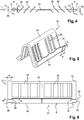
- the figure 2 is a view a perspective view of part of the beam of the heat exchange device of the figure 1 .
- the figure 2 specifies the shape of the tubes 8 and tabs 10 and their arrangement relative to each other.
- a heat exchange interlayer 10 of corrugated appearance As shown in figure 1 between two tubes 8 is arranged a heat exchange interlayer 10 of corrugated appearance.
- Each interlayer 10 is made in the form of a sheet or strip of folded metal metal, for example aluminum alloy.
- Each interlayer 10 is provided with louvers 26 made by cutting in the metal strip 20.
- the corrugated insert 10 is made, for example by successive bends of the metal strip sometimes called "strip".
- the insert 10 has a succession of planar portions 20 arranged such that two adjacent planar portions 20 are interconnected by a connecting portion 24.
- the heat exchange device 2 is traversed by a flow of air F. It follows that the bundle of tubes 8 and spacers 10 is traversed by the air flow F.
- the heat exchange device 2 thus has an upstream face constituting the inlet face of the air flow F in the heat exchange device 2 and a downstream face constituting the outlet face of the air flow. F of heat exchange device 2.
- the interlayer 10 also includes a localized allowance 30.
- This localized allowance 30 makes it possible to increase the rigidity of the insert 10 and thus to contribute to increasing the holding of the heat exchange device 2.
- two localized thicknesses 30 are arranged at the two ends of the spacer 10 in the flow direction of the air flow F.
- the first localized allowance 30 is disposed at the upstream face of the device.
- heat exchange 2 and the second localized excess thickness 30 is disposed at the downstream face of the heat exchange device 2.
- the localized excess thickness 30 is achieved by localized turning, in particular by folding, on a first length A of the metal strip 20 constituting the insert 10.
- the metal strip is at a first thickness Th1
- the extra thickness located at a second thickness Th2, such that the second thickness Th2 is equal to twice the first thickness Th1.
- the interlayer 10 is such that it comprises a first zone having the first thickness Th1 and at least a second zone having the second thickness Th2.
- Such an embodiment makes it possible to have a first thickness Th1 that is less than or equal to twice the second thickness Th2.
- Th1 is less than the second thickness Th2.
- the localized excess thickness 30 is thinned, for example by rolling, in order to reduce the size of the localized allowance and obtain the second thickness Th2.
- the second thickness Th2 it is desirable for the second thickness Th2 to be between one and a half times and twice the first thickness Th1.
- the present invention allows the localized thicknesses 30 define extremal stops having a height h2 at least equal to the difference between the second thickness Th2 and the first thickness Th1.
- Such end stops also contribute to maintaining the position of the spacers 10 between the tubes 8. Indeed, as presented especially in figure 2 , the spacers 10 are maintained in a transverse direction, that is to say in the direction of flow of the air flow F which is perpendicular to the median plane.
- the localized thickening 30 by thinning a first portion of the insert 10, in particular by machining operations.
- the first portion of the spacer 10 which is thinned is located symmetrically with respect to the median plane of the bundle of tubes 8 and spacers 10.
- the median plane is a plane equidistant from the upstream and downstream faces of the device heat exchange 2 and parallel thereto.
- FIG. 3 represents a sectional view according to the line III-III of the beam portion of the heat exchange device 2 of the figure 2 .
- the end stops come into contact with a peripheral wall 40 of the tube 8.
- the contact is made at the two small sides of the tube 8 which connect two long sides of the tubes 8 which are in contact with the insert 10 .
- the spacers 10 are placed in position and held so that they can not move between the tubes 8 during the stressing for the mounting of the heat exchange device 2.
- the two localized thicknesses 30 are arranged on the same side of the insert 10.
- This embodiment makes it possible to have two end stops on either side of the same tube 8 at the same section along a plane perpendicular to the median plane and to the upstream and downstream faces of the heat exchange device 2.
- the tabs 10 is held in position on the tube 8.
- the two localized thicknesses 30 are arranged on either side of the insert 10. This is more particularly detailed in FIG. figure 4 which is a sectional view along line IV-IV of the figure 3 .
- the end of the spacer 10 disposed on the downstream face has a localized extra thickness 30 disposed of a first next to the tab 10.
- the end of the insert 10 disposed on the upstream face has a localized extra thickness 30 disposed on a second side of the insert 10, opposite the first side.
- the figure 5 illustrates a perspective view of the embodiment of the interlayer according to the figure 4 .
- the present invention finds particular application in heat exchange devices for a heating, ventilation and / or air conditioning system for motor vehicles, such as an evaporator, a condenser or a gas cooler or a radiator. heater.
- the examples described above are based on heat exchange devices comprising tubes of folded types.
- the present invention also covers embodiments of plate tubes or extruded tubes.
- fluid circulation tubes 8 are of the 'single channel' type.
- the tubes 8 described here are only exemplary.
- Other types of tubes can be used here as fluid circulation tubes.
- the present invention also covers the embodiments in which the tubes 8 are provided with internal partitions delimiting several internal channels.
- Such tubes are generally referred to as “multichannel tubes”.
- the tubes 8 are known as "multichannel flat tubes”.
- the figure 6 illustrates an alternative embodiment of the present invention.
- the tube 8 comprises a localized deformation 32.
- the localized deformation 32 makes it possible to create a space adapted to receive the localized thickening 30 of the interlayer 10.
- the localized deformation 32 is arranged at the end portions 36 of the tube 8.
- the localized deformation 32 is such that it cooperates by complementarity of form with the localized extra thickness 30 of the insert 10.
- the tube 8 has a central portion 34 having a thickness e1 and two end portions 36 disposed on either side of the central portion 34.
- Each end portion 36 has a thickness e2.
- the thickness e1 is equal to the thickness e2 plus two times the height h2 of the end stops of the insert 10.
- the embodiment of the figure 6 also shows a particular embodiment of the corrugated interlayer 10.
- the insert 10 has two localized thickenings 30 on each side of the insert 10, a total of four localized thicknesses 30.
- Such an interlayer 10 results, in particular, from an inverted double folding, that is to say in two opposite directions, of the metal strip over a first length (A) of the ends of the insert 10. Consequently, this double folding can be reduced in thickness by a thinning operation, preferably by rolling as described above.
- Such an embodiment also has the same advantages of maintaining the spacers 10 in the bundle of tubes 8 during the stressing for the mounting of the heat exchange device 2.
- the present invention is not limited to evaporators. It is of interest for all types of heat exchange devices such as condensers, gas coolers, heating radiators, ...
Landscapes
- Physics & Mathematics (AREA)
- Engineering & Computer Science (AREA)
- Geometry (AREA)
- Thermal Sciences (AREA)
- Mechanical Engineering (AREA)
- General Engineering & Computer Science (AREA)
- Heat-Exchange Devices With Radiators And Conduit Assemblies (AREA)
- Cell Separators (AREA)
Applications Claiming Priority (1)
| Application Number | Priority Date | Filing Date | Title |
|---|---|---|---|
| FR0900160A FR2941040B1 (fr) | 2009-01-15 | 2009-01-15 | Intercalaire d'echange de chaleur pour un dispositif d'echange de chaleur |
Publications (2)
| Publication Number | Publication Date |
|---|---|
| EP2208955A1 EP2208955A1 (fr) | 2010-07-21 |
| EP2208955B1 true EP2208955B1 (fr) | 2017-09-13 |
Family
ID=40568321
Family Applications (1)
| Application Number | Title | Priority Date | Filing Date |
|---|---|---|---|
| EP10150574.1A Active EP2208955B1 (fr) | 2009-01-15 | 2010-01-12 | Intercalaire d'échange de chaleur pour un dispositif d'échange de chaleur. |
Country Status (6)
| Country | Link |
|---|---|
| US (1) | US20100175863A1 (es) |
| EP (1) | EP2208955B1 (es) |
| JP (1) | JP5539742B2 (es) |
| CN (1) | CN101793477A (es) |
| ES (1) | ES2649039T3 (es) |
| FR (1) | FR2941040B1 (es) |
Families Citing this family (13)
| Publication number | Priority date | Publication date | Assignee | Title |
|---|---|---|---|---|
| WO2012027098A2 (en) * | 2010-08-24 | 2012-03-01 | Carrier Corporation | Microchannel heat exchanger fin |
| CN102879483A (zh) * | 2011-07-13 | 2013-01-16 | 江苏汉邦科技有限公司 | 超临界流体色谱仪(sfc)以及用于其中的液态co2恒温装置 |
| US10113812B2 (en) * | 2013-02-18 | 2018-10-30 | Denso Corporation | Heat exchanger and manufacturing method thereof |
| EP2984433A1 (en) * | 2013-04-10 | 2016-02-17 | Carrier Corporation | Folded tube multiple bank heat exchange unit |
| DE102014200680A1 (de) * | 2014-01-16 | 2015-07-16 | Mahle International Gmbh | Wärmeübertrager |
| FR3037388B1 (fr) * | 2015-06-12 | 2019-07-26 | Valeo Systemes Thermiques | Ailette d'un echangeur thermique notamment pour vehicule automobile, et echangeur thermique correspondant |
| EP3255368A1 (en) * | 2016-06-09 | 2017-12-13 | Valeo Systemes Thermiques | Heat exchanger, especially a gas radiator or a condenser for a car |
| JP2018009731A (ja) * | 2016-07-13 | 2018-01-18 | 株式会社ティラド | 熱交換器のコア部構造 |
| US10451360B2 (en) | 2016-10-24 | 2019-10-22 | Hamilton Sundstrand Corporation | Heat exchanger with integral anti-icing |
| CN110073167B (zh) * | 2016-12-21 | 2021-01-01 | 三菱电机株式会社 | 热交换器及其制造方法以及制冷循环装置 |
| FR3066014A1 (fr) * | 2017-05-02 | 2018-11-09 | Valeo Systemes Thermiques | Echangeur de chaleur avec dispositif de protection et procede de fabrication associe |
| JPWO2022180823A1 (es) * | 2021-02-26 | 2022-09-01 | ||
| WO2023199400A1 (ja) * | 2022-04-12 | 2023-10-19 | 三菱電機株式会社 | 熱交換器および冷凍サイクル装置 |
Citations (1)
| Publication number | Priority date | Publication date | Assignee | Title |
|---|---|---|---|---|
| JPS53126070U (es) * | 1977-03-16 | 1978-10-06 |
Family Cites Families (9)
| Publication number | Priority date | Publication date | Assignee | Title |
|---|---|---|---|---|
| US1878511A (en) * | 1929-04-27 | 1932-09-20 | Harrison Radiator Corp | Radiator core for automobile cooling systems |
| GB1027366A (en) * | 1962-11-24 | 1966-04-27 | Svenska Metallverken Ab | An improved radiator and method of making it |
| JPS6082787A (ja) * | 1983-10-13 | 1985-05-10 | Matsushita Electric Ind Co Ltd | フイン付熱交換器 |
| JPH11148795A (ja) * | 1997-11-14 | 1999-06-02 | Toyo Radiator Co Ltd | 複合型熱交換器 |
| JP4456750B2 (ja) * | 2000-11-10 | 2010-04-28 | 株式会社ティラド | コルゲートフィン型熱交換器およびその製造方法 |
| JP2003083691A (ja) * | 2001-09-06 | 2003-03-19 | Toyo Radiator Co Ltd | 熱交換器用コルゲートフィンおよびその製造方法 |
| JP2003322486A (ja) * | 2002-05-07 | 2003-11-14 | Japan Climate Systems Corp | 熱交換器 |
| US8408283B2 (en) * | 2007-06-28 | 2013-04-02 | Centrum Equities Acquisition, Llc | Heat exchanger fin with ribbed hem |
| EP2106520B1 (en) * | 2007-01-12 | 2014-11-19 | Vista-Pro Automotive, LLC | Heat exchanger fin |
-
2009
- 2009-01-15 FR FR0900160A patent/FR2941040B1/fr not_active Expired - Fee Related
-
2010
- 2010-01-12 EP EP10150574.1A patent/EP2208955B1/fr active Active
- 2010-01-12 ES ES10150574.1T patent/ES2649039T3/es active Active
- 2010-01-14 JP JP2010005376A patent/JP5539742B2/ja active Active
- 2010-01-15 US US12/688,352 patent/US20100175863A1/en not_active Abandoned
- 2010-01-15 CN CN201010003987A patent/CN101793477A/zh active Pending
Patent Citations (1)
| Publication number | Priority date | Publication date | Assignee | Title |
|---|---|---|---|---|
| JPS53126070U (es) * | 1977-03-16 | 1978-10-06 |
Also Published As
| Publication number | Publication date |
|---|---|
| US20100175863A1 (en) | 2010-07-15 |
| JP5539742B2 (ja) | 2014-07-02 |
| FR2941040A1 (fr) | 2010-07-16 |
| FR2941040B1 (fr) | 2012-08-31 |
| ES2649039T3 (es) | 2018-01-09 |
| CN101793477A (zh) | 2010-08-04 |
| JP2010181140A (ja) | 2010-08-19 |
| EP2208955A1 (fr) | 2010-07-21 |
Similar Documents
| Publication | Publication Date | Title |
|---|---|---|
| EP2208955B1 (fr) | Intercalaire d'échange de chaleur pour un dispositif d'échange de chaleur. | |
| FR2941522A1 (fr) | Echangeur de chaleur pour deux fluides, en particulier evaporateur de stockage pour dispositif de climatisation | |
| EP2118608B1 (fr) | Echangeur de chaleur et ensemble intégré incorporant un tel échangeur | |
| EP2273224B1 (fr) | Unité d'échange thermique et échangeur thermique correspondant, procédé de réalisation d'une unité d'échange thermique | |
| WO2009000581A1 (fr) | Module d'echange de chaleur pour deux circuits d'echange de chaleur | |
| EP1762808A1 (fr) | Elément de circuit à tubes plats, et échangeur de chaleur muni de tels éléments de circuit | |
| EP2105694A1 (fr) | Plaque d'échangeur de chaleur | |
| FR2973106A1 (fr) | Renfort de liaison entre plaques d'un echangeur de chaleur | |
| FR2898405A1 (fr) | Echangeur de chaleur, en particulier refroidisseur de gaz, comportant deux nappes de tubes reliees | |
| EP2105693B1 (fr) | Echangeur de chaleur à puissance frigorifique élevée | |
| US20090120617A1 (en) | Tube For Heat Exchanger | |
| FR2832788A1 (fr) | Profils de tubes pour echangeur thermique | |
| FR2849174A1 (fr) | Ailette d'echange de chaleur, notamment de refroidissement, module d'echange de chaleur comprenant une telle ailette et procede de fabrication d'echangeurs de chaleur utilisant ladite ailette | |
| EP1676088B1 (fr) | Élément de circuit hydraulique pour échangeur de chaleur , et échangeur de chaleur ainsi obtenu | |
| EP2253917A1 (fr) | Plaque de tube pour un échangeur de chaleur | |
| FR2923589A1 (fr) | Echangeur de chaleur brase de type fluide/fluide | |
| FR3066015A1 (fr) | Tube pour echangeur thermique et echangeur thermique correspondant | |
| EP2764317B1 (fr) | Echangeur thermique | |
| WO2023001791A1 (fr) | Elements de perturbation avances pour l'amelioration de la performance des tubes de radiateurs basse temperature | |
| FR3073611B1 (fr) | Tube pour echangeur de chaleur avec dispositif de perturbation de geometrie variable | |
| EP3308096B1 (fr) | Echangeur de chaleur pour vehicule automobile | |
| WO2023099315A1 (fr) | Elements de perturbation avances pour l'amelioration de la performance des tubes | |
| WO2014048960A1 (fr) | Plaque collectrice pour echangeur de chaleur | |
| FR2980739A1 (fr) | Tube de radiateur de refroidissement pour vehicule automobile et radiateur de refroidissement pour vehicule automobile comprenant un tel tube. | |
| EP4018146A1 (fr) | Echangeur de chaleur notamment pour véhicule automobile et procédé de fabrication d'un tel échangeur de chaleur |
Legal Events
| Date | Code | Title | Description |
|---|---|---|---|
| PUAI | Public reference made under article 153(3) epc to a published international application that has entered the european phase |
Free format text: ORIGINAL CODE: 0009012 |
|
| AK | Designated contracting states |
Kind code of ref document: A1 Designated state(s): AT BE BG CH CY CZ DE DK EE ES FI FR GB GR HR HU IE IS IT LI LT LU LV MC MK MT NL NO PL PT RO SE SI SK SM TR |
|
| AX | Request for extension of the european patent |
Extension state: AL BA RS |
|
| RAP3 | Party data changed (applicant data changed or rights of an application transferred) |
Owner name: VALEO SYSTEMES THERMIQUES |
|
| 17P | Request for examination filed |
Effective date: 20110120 |
|
| REG | Reference to a national code |
Ref country code: DE Ref legal event code: R079 Ref document number: 602010045156 Country of ref document: DE Free format text: PREVIOUS MAIN CLASS: F28F0001120000 Ipc: F28F0001020000 |
|
| RIC1 | Information provided on ipc code assigned before grant |
Ipc: F28F 1/12 20060101ALI20170216BHEP Ipc: F28F 1/02 20060101AFI20170216BHEP |
|
| GRAP | Despatch of communication of intention to grant a patent |
Free format text: ORIGINAL CODE: EPIDOSNIGR1 |
|
| INTG | Intention to grant announced |
Effective date: 20170412 |
|
| GRAS | Grant fee paid |
Free format text: ORIGINAL CODE: EPIDOSNIGR3 |
|
| GRAA | (expected) grant |
Free format text: ORIGINAL CODE: 0009210 |
|
| AK | Designated contracting states |
Kind code of ref document: B1 Designated state(s): AT BE BG CH CY CZ DE DK EE ES FI FR GB GR HR HU IE IS IT LI LT LU LV MC MK MT NL NO PL PT RO SE SI SK SM TR |
|
| REG | Reference to a national code |
Ref country code: GB Ref legal event code: FG4D Free format text: NOT ENGLISH |
|
| REG | Reference to a national code |
Ref country code: CH Ref legal event code: EP |
|
| REG | Reference to a national code |
Ref country code: IE Ref legal event code: FG4D Free format text: LANGUAGE OF EP DOCUMENT: FRENCH |
|
| REG | Reference to a national code |
Ref country code: AT Ref legal event code: REF Ref document number: 928576 Country of ref document: AT Kind code of ref document: T Effective date: 20171015 |
|
| REG | Reference to a national code |
Ref country code: DE Ref legal event code: R096 Ref document number: 602010045156 Country of ref document: DE |
|
| REG | Reference to a national code |
Ref country code: ES Ref legal event code: FG2A Ref document number: 2649039 Country of ref document: ES Kind code of ref document: T3 Effective date: 20180109 |
|
| REG | Reference to a national code |
Ref country code: NL Ref legal event code: MP Effective date: 20170913 |
|
| REG | Reference to a national code |
Ref country code: LT Ref legal event code: MG4D |
|
| PG25 | Lapsed in a contracting state [announced via postgrant information from national office to epo] |
Ref country code: NO Free format text: LAPSE BECAUSE OF FAILURE TO SUBMIT A TRANSLATION OF THE DESCRIPTION OR TO PAY THE FEE WITHIN THE PRESCRIBED TIME-LIMIT Effective date: 20171213 Ref country code: HR Free format text: LAPSE BECAUSE OF FAILURE TO SUBMIT A TRANSLATION OF THE DESCRIPTION OR TO PAY THE FEE WITHIN THE PRESCRIBED TIME-LIMIT Effective date: 20170913 Ref country code: LT Free format text: LAPSE BECAUSE OF FAILURE TO SUBMIT A TRANSLATION OF THE DESCRIPTION OR TO PAY THE FEE WITHIN THE PRESCRIBED TIME-LIMIT Effective date: 20170913 Ref country code: SE Free format text: LAPSE BECAUSE OF FAILURE TO SUBMIT A TRANSLATION OF THE DESCRIPTION OR TO PAY THE FEE WITHIN THE PRESCRIBED TIME-LIMIT Effective date: 20170913 Ref country code: FI Free format text: LAPSE BECAUSE OF FAILURE TO SUBMIT A TRANSLATION OF THE DESCRIPTION OR TO PAY THE FEE WITHIN THE PRESCRIBED TIME-LIMIT Effective date: 20170913 |
|
| REG | Reference to a national code |
Ref country code: FR Ref legal event code: PLFP Year of fee payment: 9 |
|
| REG | Reference to a national code |
Ref country code: AT Ref legal event code: MK05 Ref document number: 928576 Country of ref document: AT Kind code of ref document: T Effective date: 20170913 |
|
| PG25 | Lapsed in a contracting state [announced via postgrant information from national office to epo] |
Ref country code: GR Free format text: LAPSE BECAUSE OF FAILURE TO SUBMIT A TRANSLATION OF THE DESCRIPTION OR TO PAY THE FEE WITHIN THE PRESCRIBED TIME-LIMIT Effective date: 20171214 Ref country code: BG Free format text: LAPSE BECAUSE OF FAILURE TO SUBMIT A TRANSLATION OF THE DESCRIPTION OR TO PAY THE FEE WITHIN THE PRESCRIBED TIME-LIMIT Effective date: 20171213 Ref country code: LV Free format text: LAPSE BECAUSE OF FAILURE TO SUBMIT A TRANSLATION OF THE DESCRIPTION OR TO PAY THE FEE WITHIN THE PRESCRIBED TIME-LIMIT Effective date: 20170913 |
|
| PG25 | Lapsed in a contracting state [announced via postgrant information from national office to epo] |
Ref country code: NL Free format text: LAPSE BECAUSE OF FAILURE TO SUBMIT A TRANSLATION OF THE DESCRIPTION OR TO PAY THE FEE WITHIN THE PRESCRIBED TIME-LIMIT Effective date: 20170913 |
|
| PG25 | Lapsed in a contracting state [announced via postgrant information from national office to epo] |
Ref country code: PL Free format text: LAPSE BECAUSE OF FAILURE TO SUBMIT A TRANSLATION OF THE DESCRIPTION OR TO PAY THE FEE WITHIN THE PRESCRIBED TIME-LIMIT Effective date: 20170913 Ref country code: RO Free format text: LAPSE BECAUSE OF FAILURE TO SUBMIT A TRANSLATION OF THE DESCRIPTION OR TO PAY THE FEE WITHIN THE PRESCRIBED TIME-LIMIT Effective date: 20170913 |
|
| PG25 | Lapsed in a contracting state [announced via postgrant information from national office to epo] |
Ref country code: SM Free format text: LAPSE BECAUSE OF FAILURE TO SUBMIT A TRANSLATION OF THE DESCRIPTION OR TO PAY THE FEE WITHIN THE PRESCRIBED TIME-LIMIT Effective date: 20170913 Ref country code: AT Free format text: LAPSE BECAUSE OF FAILURE TO SUBMIT A TRANSLATION OF THE DESCRIPTION OR TO PAY THE FEE WITHIN THE PRESCRIBED TIME-LIMIT Effective date: 20170913 Ref country code: IS Free format text: LAPSE BECAUSE OF FAILURE TO SUBMIT A TRANSLATION OF THE DESCRIPTION OR TO PAY THE FEE WITHIN THE PRESCRIBED TIME-LIMIT Effective date: 20180113 Ref country code: IT Free format text: LAPSE BECAUSE OF FAILURE TO SUBMIT A TRANSLATION OF THE DESCRIPTION OR TO PAY THE FEE WITHIN THE PRESCRIBED TIME-LIMIT Effective date: 20170913 Ref country code: SK Free format text: LAPSE BECAUSE OF FAILURE TO SUBMIT A TRANSLATION OF THE DESCRIPTION OR TO PAY THE FEE WITHIN THE PRESCRIBED TIME-LIMIT Effective date: 20170913 Ref country code: EE Free format text: LAPSE BECAUSE OF FAILURE TO SUBMIT A TRANSLATION OF THE DESCRIPTION OR TO PAY THE FEE WITHIN THE PRESCRIBED TIME-LIMIT Effective date: 20170913 |
|
| REG | Reference to a national code |
Ref country code: DE Ref legal event code: R097 Ref document number: 602010045156 Country of ref document: DE |
|
| PLBE | No opposition filed within time limit |
Free format text: ORIGINAL CODE: 0009261 |
|
| STAA | Information on the status of an ep patent application or granted ep patent |
Free format text: STATUS: NO OPPOSITION FILED WITHIN TIME LIMIT |
|
| PG25 | Lapsed in a contracting state [announced via postgrant information from national office to epo] |
Ref country code: DK Free format text: LAPSE BECAUSE OF FAILURE TO SUBMIT A TRANSLATION OF THE DESCRIPTION OR TO PAY THE FEE WITHIN THE PRESCRIBED TIME-LIMIT Effective date: 20170913 |
|
| 26N | No opposition filed |
Effective date: 20180614 |
|
| REG | Reference to a national code |
Ref country code: CH Ref legal event code: PL |
|
| GBPC | Gb: european patent ceased through non-payment of renewal fee |
Effective date: 20180112 |
|
| PG25 | Lapsed in a contracting state [announced via postgrant information from national office to epo] |
Ref country code: MT Free format text: LAPSE BECAUSE OF FAILURE TO SUBMIT A TRANSLATION OF THE DESCRIPTION OR TO PAY THE FEE WITHIN THE PRESCRIBED TIME-LIMIT Effective date: 20170913 |
|
| PG25 | Lapsed in a contracting state [announced via postgrant information from national office to epo] |
Ref country code: LU Free format text: LAPSE BECAUSE OF NON-PAYMENT OF DUE FEES Effective date: 20180112 |
|
| REG | Reference to a national code |
Ref country code: IE Ref legal event code: MM4A |
|
| REG | Reference to a national code |
Ref country code: BE Ref legal event code: MM Effective date: 20180131 |
|
| PG25 | Lapsed in a contracting state [announced via postgrant information from national office to epo] |
Ref country code: BE Free format text: LAPSE BECAUSE OF NON-PAYMENT OF DUE FEES Effective date: 20180131 Ref country code: SI Free format text: LAPSE BECAUSE OF FAILURE TO SUBMIT A TRANSLATION OF THE DESCRIPTION OR TO PAY THE FEE WITHIN THE PRESCRIBED TIME-LIMIT Effective date: 20170913 Ref country code: GB Free format text: LAPSE BECAUSE OF NON-PAYMENT OF DUE FEES Effective date: 20180112 Ref country code: CH Free format text: LAPSE BECAUSE OF NON-PAYMENT OF DUE FEES Effective date: 20180131 Ref country code: LI Free format text: LAPSE BECAUSE OF NON-PAYMENT OF DUE FEES Effective date: 20180131 |
|
| PG25 | Lapsed in a contracting state [announced via postgrant information from national office to epo] |
Ref country code: IE Free format text: LAPSE BECAUSE OF NON-PAYMENT OF DUE FEES Effective date: 20180112 |
|
| PG25 | Lapsed in a contracting state [announced via postgrant information from national office to epo] |
Ref country code: MC Free format text: LAPSE BECAUSE OF FAILURE TO SUBMIT A TRANSLATION OF THE DESCRIPTION OR TO PAY THE FEE WITHIN THE PRESCRIBED TIME-LIMIT Effective date: 20170913 |
|
| PG25 | Lapsed in a contracting state [announced via postgrant information from national office to epo] |
Ref country code: TR Free format text: LAPSE BECAUSE OF FAILURE TO SUBMIT A TRANSLATION OF THE DESCRIPTION OR TO PAY THE FEE WITHIN THE PRESCRIBED TIME-LIMIT Effective date: 20170913 |
|
| PG25 | Lapsed in a contracting state [announced via postgrant information from national office to epo] |
Ref country code: HU Free format text: LAPSE BECAUSE OF FAILURE TO SUBMIT A TRANSLATION OF THE DESCRIPTION OR TO PAY THE FEE WITHIN THE PRESCRIBED TIME-LIMIT; INVALID AB INITIO Effective date: 20100112 Ref country code: PT Free format text: LAPSE BECAUSE OF FAILURE TO SUBMIT A TRANSLATION OF THE DESCRIPTION OR TO PAY THE FEE WITHIN THE PRESCRIBED TIME-LIMIT Effective date: 20170913 |
|
| PG25 | Lapsed in a contracting state [announced via postgrant information from national office to epo] |
Ref country code: CY Free format text: LAPSE BECAUSE OF FAILURE TO SUBMIT A TRANSLATION OF THE DESCRIPTION OR TO PAY THE FEE WITHIN THE PRESCRIBED TIME-LIMIT Effective date: 20170913 Ref country code: MK Free format text: LAPSE BECAUSE OF NON-PAYMENT OF DUE FEES Effective date: 20170913 |
|
| PGFP | Annual fee paid to national office [announced via postgrant information from national office to epo] |
Ref country code: CZ Payment date: 20211221 Year of fee payment: 13 |
|
| PGFP | Annual fee paid to national office [announced via postgrant information from national office to epo] |
Ref country code: ES Payment date: 20220203 Year of fee payment: 13 |
|
| PGFP | Annual fee paid to national office [announced via postgrant information from national office to epo] |
Ref country code: FR Payment date: 20230125 Year of fee payment: 14 |
|
| P01 | Opt-out of the competence of the unified patent court (upc) registered |
Effective date: 20230528 |
|
| PG25 | Lapsed in a contracting state [announced via postgrant information from national office to epo] |
Ref country code: CZ Free format text: LAPSE BECAUSE OF NON-PAYMENT OF DUE FEES Effective date: 20230112 |
|
| REG | Reference to a national code |
Ref country code: ES Ref legal event code: FD2A Effective date: 20240326 |
|
| PG25 | Lapsed in a contracting state [announced via postgrant information from national office to epo] |
Ref country code: ES Free format text: LAPSE BECAUSE OF NON-PAYMENT OF DUE FEES Effective date: 20230113 |
|
| PG25 | Lapsed in a contracting state [announced via postgrant information from national office to epo] |
Ref country code: ES Free format text: LAPSE BECAUSE OF NON-PAYMENT OF DUE FEES Effective date: 20230113 |
|
| PGFP | Annual fee paid to national office [announced via postgrant information from national office to epo] |
Ref country code: DE Payment date: 20240115 Year of fee payment: 15 |