EP2208944A1 - Device monitor and remote monitoring system - Google Patents
Device monitor and remote monitoring system Download PDFInfo
- Publication number
- EP2208944A1 EP2208944A1 EP08834531A EP08834531A EP2208944A1 EP 2208944 A1 EP2208944 A1 EP 2208944A1 EP 08834531 A EP08834531 A EP 08834531A EP 08834531 A EP08834531 A EP 08834531A EP 2208944 A1 EP2208944 A1 EP 2208944A1
- Authority
- EP
- European Patent Office
- Prior art keywords
- anomaly
- monitoring device
- equipment
- remote monitoring
- unit
- Prior art date
- Legal status (The legal status is an assumption and is not a legal conclusion. Google has not performed a legal analysis and makes no representation as to the accuracy of the status listed.)
- Granted
Links
Images


Classifications
-
- F—MECHANICAL ENGINEERING; LIGHTING; HEATING; WEAPONS; BLASTING
- F24—HEATING; RANGES; VENTILATING
- F24F—AIR-CONDITIONING; AIR-HUMIDIFICATION; VENTILATION; USE OF AIR CURRENTS FOR SCREENING
- F24F11/00—Control or safety arrangements
- F24F11/30—Control or safety arrangements for purposes related to the operation of the system, e.g. for safety or monitoring
- F24F11/32—Responding to malfunctions or emergencies
- F24F11/38—Failure diagnosis
-
- F—MECHANICAL ENGINEERING; LIGHTING; HEATING; WEAPONS; BLASTING
- F24—HEATING; RANGES; VENTILATING
- F24F—AIR-CONDITIONING; AIR-HUMIDIFICATION; VENTILATION; USE OF AIR CURRENTS FOR SCREENING
- F24F11/00—Control or safety arrangements
- F24F11/30—Control or safety arrangements for purposes related to the operation of the system, e.g. for safety or monitoring
-
- F—MECHANICAL ENGINEERING; LIGHTING; HEATING; WEAPONS; BLASTING
- F24—HEATING; RANGES; VENTILATING
- F24F—AIR-CONDITIONING; AIR-HUMIDIFICATION; VENTILATION; USE OF AIR CURRENTS FOR SCREENING
- F24F11/00—Control or safety arrangements
- F24F11/30—Control or safety arrangements for purposes related to the operation of the system, e.g. for safety or monitoring
- F24F11/32—Responding to malfunctions or emergencies
-
- F—MECHANICAL ENGINEERING; LIGHTING; HEATING; WEAPONS; BLASTING
- F24—HEATING; RANGES; VENTILATING
- F24F—AIR-CONDITIONING; AIR-HUMIDIFICATION; VENTILATION; USE OF AIR CURRENTS FOR SCREENING
- F24F11/00—Control or safety arrangements
- F24F11/50—Control or safety arrangements characterised by user interfaces or communication
- F24F11/52—Indication arrangements, e.g. displays
-
- F—MECHANICAL ENGINEERING; LIGHTING; HEATING; WEAPONS; BLASTING
- F24—HEATING; RANGES; VENTILATING
- F24F—AIR-CONDITIONING; AIR-HUMIDIFICATION; VENTILATION; USE OF AIR CURRENTS FOR SCREENING
- F24F11/00—Control or safety arrangements
- F24F11/50—Control or safety arrangements characterised by user interfaces or communication
- F24F11/56—Remote control
-
- G—PHYSICS
- G08—SIGNALLING
- G08B—SIGNALLING SYSTEMS, e.g. PERSONAL CALLING SYSTEMS; ORDER TELEGRAPHS; ALARM SYSTEMS
- G08B25/00—Alarm systems in which the location of the alarm condition is signalled to a central station, e.g. fire or police telegraphic systems
- G08B25/01—Alarm systems in which the location of the alarm condition is signalled to a central station, e.g. fire or police telegraphic systems characterised by the transmission medium
- G08B25/10—Alarm systems in which the location of the alarm condition is signalled to a central station, e.g. fire or police telegraphic systems characterised by the transmission medium using wireless transmission systems
Definitions
- the present invention relates to an equipment monitoring device and to a remote monitoring system.
- Monitoring systems have been used in the past for receiving equipment information from an air conditioning device or other equipment and monitoring the operational status of the equipment.
- an equipment monitoring device is provided in a building (property) in which the equipment is provided, and when the equipment monitoring device detects an anomaly in the equipment, an anomaly report is issued from the equipment monitoring device to a remote monitoring device that is provided at a remote location from the equipment.
- anomaly information that relates to the anomaly report is sent to a manager or other person responsible for the equipment, and action is taken with respect to the anomaly.
- An equipment monitoring device has therefore been proposed for restricting anomaly reports from the equipment monitoring device to the remote monitoring system when the detected subject of an anomaly is the same as that of a previously detected anomaly in order to reduce the amount of anomaly reports received by the remote monitoring device and make anomalies easier for a manager or the like to identify.
- An object of the present invention is to provide an equipment monitoring device or remote monitoring system whereby the number of anomaly reports issued from the equipment monitoring device to a remote monitoring device can be reduced, and information relating to anomalies that require an urgent response can easily be identified.
- An equipment monitoring device is an equipment monitoring device for monitoring equipment and transmitting an operational status of the equipment to a remote monitoring device that is provided in a remote location relative to the equipment, and the equipment monitoring device comprises an anomaly detection unit, an anomaly identifying unit, and an anomaly reporting unit.
- the anomaly detection unit detects an anomaly that occurs in the equipment.
- the anomaly identifying unit identifies the anomaly on the basis of at least one of an anomaly category and an anomaly level.
- the anomaly reporting unit issues an anomaly report that is a report of the anomaly to the remote monitoring device, on the basis of the results of an identification made by the anomaly identifying unit.
- Anomalies in a “category” are anomalies that have the same type of subject; e.g., a failure of the same part, an anomaly detected by the same sensor, and the like.
- the "level” of an anomaly refers to the severity of an anomaly, such as “minor,” or “severe,” determined based on whether an anomaly requires an urgent response.
- an anomaly report is issued to the remote monitoring device on the basis of the result of the anomaly identifying unit identifying the anomaly on the basis of at least one of the anomaly category and the anomaly level.
- the number of anomaly reports received by the remote monitoring device can be reduced, and anomalies that require an urgent response can easily be identified in the remote monitoring device.
- An equipment monitoring device is the equipment monitoring device according to the first aspect of the present invention, wherein the anomaly identifying unit compares the category and the level of a reported anomaly which is the anomaly already reported to the remote monitoring device, and the category and the level of a new anomaly which is a newly detected the anomaly.
- the anomaly reporting unit issues an anomaly report to the remote monitoring device on the basis of the result of comparison between the category and level of the new anomaly and the category and level of the already reported anomaly by the anomaly identifying unit.
- the amount of information to be processed by the remote monitoring device can be reduced by preventing redundant reception of anomalies that relate to an anomaly report already received by the remote monitoring device.
- An equipment monitoring device is the equipment monitoring device according to the second aspect of the present invention, wherein the anomaly reporting unit does not issue the anomaly report to the remote monitoring device when the category of the new anomaly matches the category of the already reported anomaly, and at least one of the following cases occurs: the level of the new anomaly matches the level of the already reported anomaly, and the level of the new anomaly is lower than the level of the already reported anomaly.
- anomaly reporting is restricted by the relationship between the level of the new anomaly and the level of an already reported anomaly when the category of the new anomaly and the category of the already reported anomaly are the same.
- the equipment monitoring device does not issue an anomaly report for an anomaly having at least one of the same level as an already reported anomaly and a level lower than the level of an already reported anomaly, it is possible to reduce the amount of information relating to anomalies that is received by the remote monitoring device.
- An equipment monitoring device is the equipment monitoring device according to the second or third aspect of the present invention, further comprising a condition acquiring unit.
- the condition acquiring unit acquires a non-reporting condition of the anomaly from the remote monitoring device. Information relating to the already reported anomaly is obtained based on the non-reporting condition acquired by the condition acquiring unit.
- information relating to the already reported anomaly to be compared with a new anomaly is obtained according to a non-reporting condition of the anomaly that is acquired from the remote monitoring device.
- the non-reporting condition is updated in the remote monitoring device, and it is thereby possible to change the anomaly that is reported to the remote monitoring device from the equipment monitoring device. Even in the case of an already reported anomaly that has previously been reported from the equipment monitoring device to the remote monitoring device and has thus been disallowed from being reported to the remote monitoring device, for example, by subsequently changing the subject of the non-reporting condition acquired from the remote monitoring device, the anomaly can again be reported to the remote monitoring device.
- An equipment monitoring device is the equipment monitoring device according to any of the first through fourth aspects of the present invention, further comprising a periodic reporting unit.
- the periodic reporting unit periodically transmits to the remote monitoring device at least one of an operational history that is a history of the operational status of the equipment, and a change history that is a history of changes in the anomaly.
- the equipment monitoring device of the present invention since at least one of an operational history and a change history is transmitted to the remote monitoring device, the occurrence and resolution of an anomaly can be ascertained from the change history for an anomaly not reported to the remote monitoring device.
- the status of the equipment can thereby be efficiency monitored in the remote monitoring device without issuing an anomaly report every time an anomaly occurs.
- a remote monitoring system is a remote monitoring system comprising an equipment monitoring device and a remote monitoring device, wherein the equipment monitoring device monitors an operational status of a unit of equipment, and the remote monitoring device is provided in a remote location relative to the equipment and receives information relating to the operational status from the equipment monitoring device.
- the equipment monitoring device comprises an anomaly detection unit, an anomaly identifying unit, and an anomaly reporting unit.
- the anomaly detection unit detects an anomaly that occurs in the equipment.
- the anomaly identifying unit identifies the anomaly on the basis of at least one of an anomaly category and an anomaly level.
- the anomaly reporting unit issues an anomaly report that is a report of the anomaly to the remote monitoring device, on the basis of the results of identification by the anomaly identifying unit.
- an anomaly report is issued to the remote monitoring device on the basis of the result of the anomaly identifying unit identifying the anomaly on the basis of at least one of the anomaly category and the anomaly level.
- the number of anomaly reports received by the remote monitoring device can be reduced, and anomalies that require an urgent response can easily be identified in the remote monitoring device.
- a remote monitoring system is the remote monitoring system according to the sixth aspect of the present invention, wherein the remote monitoring device comprises an anomaly report receiving unit, a non-reporting condition generating unit, and a non-reporting condition transmitting unit.
- the anomaly report receiving unit receives the anomaly report.
- the non-reporting condition generating unit generates a non-reporting condition of the anomaly report in the equipment monitoring device on the basis of information relating to the anomaly report.
- the non-reporting condition transmitting unit transmits the non-reporting condition to the equipment monitoring device.
- the non-reporting condition generating unit also updates and generates the non-reporting condition on the basis of the level.
- the non-reporting condition is updated and generated according to the level of the anomaly received by the remote monitoring device, and the anomaly report from the equipment monitoring device is issued based on the non-reporting condition.
- the timing of updating the non-reporting condition generated in the remote monitoring device therefore varies according to the level of the anomaly
- the system can be set so that minor anomalies are not reported for some time, so that severe anomalies are sequentially reported.
- a remote monitoring system is the remote monitoring system according to the sixth or seventh aspect of the present invention, wherein the remote monitoring device comprises an anomaly information transmitting unit.
- the anomaly information transmitting unit automatically transmits the anomaly information to at least one of a manager and a dealer of the equipment when the anomaly report is received by the anomaly report receiving unit.
- manager refers to a property owner or other user of the equipment.
- dealer refers to an equipment sales outlet or a service station for maintaining the equipment.
- information relating to the anomaly report received by the remote monitoring device is automatically transmitted to at least one of a manager and a dealer of the equipment.
- the manager or dealer can therefore appropriately assess the status of the equipment.
- the number of anomaly reports received by the remote monitoring device can be reduced, and anomalies that require an urgent response can easily be identified in the remote monitoring device.
- the amount of information to be processed by the remote monitoring device can be reduced by preventing redundant reception of anomalies that relate to an anomaly report already received by the remote monitoring device.
- the equipment monitoring device since the equipment monitoring device does not issue an anomaly report for an anomaly having at least one of the same level as an already reported anomaly and a level lower than the level of an already reported anomaly, it is possible to reduce the amount of information relating to anomalies that is received by the remote monitoring device.
- the non-reporting condition is updated in the remote monitoring device, and it is thereby possible to change the anomaly that is reported to the remote monitoring device from the equipment monitoring device.
- the status of the equipment can be efficiency monitored in the remote monitoring device without issuing an anomaly report every time an anomaly occurs.
- the number of anomaly reports received by the remote monitoring device can be reduced, and anomalies that require an urgent response can easily be identified in the remote monitoring device.
- the system by updating the non-reporting condition at a different time for severe anomalies and minor anomalies, for example, the system can be set so that minor anomalies are not reported for some time, so that severe anomalies are sequentially reported.
- At least one of a manager and a dealer can appropriately assess the status of the equipment.
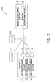
- the remote monitoring system 100 according to a first embodiment of the present invention will be described using FIGS. 1 through 7 .
- FIG 1 shows the overall structure of the remote monitoring system 100.
- the remote monitoring system 100 is a system for managing air conditioning devices 50, which are provided to a property 1, from a remote monitoring device 20 inside a remote monitoring center 2.
- An equipment monitoring device 10 is connected to each of the air conditioning devices 50, and anomalies that occur in the air conditioning devices 50 are detected by the equipment monitoring devices 10.
- the equipment monitoring devices 10 and the remote monitoring device 20 are capable of communicating with each other via an Internet line, and equipment information indicating the operational state of the air conditioning devices 50, and anomaly information indicating an anomaly in the air conditioning devices 50 are transmitted from the equipment monitoring devices 10 to the remote monitoring device 20 via the Internet line.
- the anomaly information of the air conditioning devices 50 is transmitted via the Internet line from the remote monitoring device 20 to a dealer terminal 30 provided to a dealer of the air conditioning devices 50, and to a manager terminal 31 of a manager of the air conditioning devices 50.
- manager herein refers to a property owner or other user of the equipment.
- dealer refers to an equipment sales outlet or a service station for maintaining the equipment. The structure of each component will be described in detail hereinafter.
- the numbers of air conditioning devices 50, equipment monitoring devices 10, remote monitoring devices 20, and other components in the remote monitoring system 100 are not limited to the numbers of these components shown in FIG. 1 .
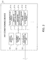
- the air conditioning device 50 in the remote monitoring system 100 will first be described using FIG. 2 .
- the air conditioning device 50 has a refrigerant circuit composed of a compressor, a heat exchanger, and other components not shown in the drawing.
- Various sensors 51a, 51b, 51c, 51d, 51e, and so on are also attached to the air conditioning device 50.
- the sensor 51a detects the temperature of a room in which the air conditioning device 50 is provided.
- the sensor 51b detects the temperature of the ambient air in the vicinity of equipment to which the air conditioning device 50 is provided.
- the sensor 51c detects the discharge temperature, which is the temperature of the refrigerant in a discharge duct of the compressor that is included in the air conditioning device 50.
- the sensor 51d detects the discharge pressure, which is the pressure of the refrigerant in the discharge duct of the compressor that is included in the air conditioning device 50.
- the sensor 51e detects the intake pressure, which is the pressure of the refrigerant in an intake duct of the compressor that is included in the air conditioning device 50.
- a current detection unit 54 for detecting a current value is also attached to the air conditioning device 50.
- the air conditioning device 50 also has an equipment control unit 52 and an equipment communication unit 53.
- the equipment communication unit 53 is connected to the equipment monitoring device 10, and transmits equipment information to the remote monitoring device 20 via the equipment monitoring device 10, as described above.
- the equipment control unit 52 controls the air conditioning device 50 according to control commands inputted from a user.
- the various sensors 51a, 51b, 51c, 51d, 51e, and so on and the current detection unit 54 are connected to the equipment control unit 52.
- the equipment control unit 52 transmits the values (equipment information) detected by the sensors 51a, 51b, 51c, 51d, 51e, and so on and the current detection unit 54 to the equipment monitoring device 10 at predetermined intervals (one minute in the present embodiment).
- the equipment control unit 52 also performs such operations as comparing the values acquired from the sensors 51a, 51b, 51c, 51d, 51e, and so on and current detection unit 54 with a predetermined threshold value at predetermined intervals (one minute in the present embodiment), and when an anomaly such as exceeding the predetermined threshold value is detected, the equipment control unit 52 transmits anomaly information indicating such to the equipment monitoring device 10.
- the equipment monitoring device 10 is primarily composed of an equipment monitoring communication unit 11, an equipment monitoring control unit 12, and an equipment monitoring storage unit 13.
- the equipment monitoring communication unit 11 is composed of a plurality of input/output ports.
- the equipment monitoring communication unit 11 is connected to the air conditioning device 50 and the remote monitoring device 20.
- the equipment monitoring communication unit 11 receives equipment information and anomaly information from the air conditioning device 50 and exchanges various signals with the remote monitoring device 20.
- the equipment monitoring storage unit 13 maintains an equipment information storage area 13a, an anomaly information storage area 13b, and a non-reporting condition storage area 13c.
- Equipment information received from the air conditioning device 50 is stored in the equipment information storage area 13a.
- the term "equipment information” refers to device names, machine codes, operational history (indicating such information as how long a device has been operating in a certain operating mode (cooling mode, heating mode, fan mode, or the like)), values detected from the sensors 51a, 51b, 51c, 51d, 51e, and so on and the current detection unit 54, and addresses allocated for managing the air conditioning devices 50.
- Equipment anomaly information is stored in the anomaly information storage area 13b.
- An anomaly in the equipment is an anomaly in the various sensor values, an anomaly in a current value, or another anomaly.
- An anomaly in a sensor value is information indicating that a value detected in the sensors 51a, 51b, 51c, 51d, 51e, and so on has exceeded a predetermined threshold value.
- An anomaly in a current value is information indicating that a current value detected by the current detection unit has exceeded a predetermined threshold value.
- the equipment monitoring control unit 12 is primarily composed of an anomaly detection unit 12a, a condition acquiring unit 12b, a periodic reporting unit 12c, an anomaly reporting unit 12d, and an anomaly identifying unit 12e.
- the anomaly detection unit 12a detects anomaly information transmitted from the air conditioning device 50.
- the condition acquiring unit 12b acquires a non-reporting condition that relates to an anomaly report transmitted from the remote monitoring device 20.
- the non-reporting condition relating to the anomaly report is a condition referenced when the anomaly reporting unit 12d issues an anomaly report to the remote monitoring device 20.
- the non-reporting condition cites an anomaly category and anomaly level for which an anomaly report to the remote monitoring device 20 is not necessary when an anomaly relating to the anomaly reports already received by the remote monitoring device 20 from the equipment monitoring device 10 is newly detected by the equipment monitoring device 10.
- the periodic reporting unit 12c transmits a change history and daily report once a day to the remote monitoring device 20.
- change history refers to a history of changes in the anomalies occurring in the air conditioning device 50, and the occurrence, resolution, time, and other characteristics of an anomaly are shown in the change history.
- the daily report indicates an operational history that is the history of the operational status of an air conditioning device 50, and the daily report is a summary of the operational history or operational state of the air conditioning device 50 for one day, based on the equipment information stored in the equipment information storage area 13a and the anomaly information stored in the anomaly information storage area 13b.
- the daily report specifically indicates the maximum and minimum values detected in the sensors 51a, 51b, 51c, 51d, 51e, and so on and current detection unit 54 for the day of the report, the cumulative operation time of the air conditioning device 50, the cumulative number of activations and deactivations, the maximum continuous operating time, and other operational details for the day of the report.
- the anomaly reporting unit 12d issues anomaly reports to the remote monitoring device 20.
- the anomaly reporting unit 12d issues anomaly reports to the remote monitoring device 20 on the basis of the results of identification by the anomaly identifying unit 12e described hereinafter.
- the anomaly identifying unit 12e compares an anomaly detected by the anomaly detection unit 12a with a non-reporting condition acquired from the remote monitoring device 20, and determines whether the anomaly is to be reported to the remote monitoring device 20. Specifically, the anomaly identifying unit 12e compares the category and level of a newly detected anomaly with the anomaly category and level indicated in the non-reporting condition, and identifies the newly detected anomaly.
- the anomaly category and anomaly level will both be described in the description of the non-reporting condition generating unit 25b in the remote monitoring device 20 described hereinafter.
- the anomaly reporting unit 12d does not issue an anomaly report to the remote monitoring device 20 when the category of the anomaly detected by the anomaly detection unit 12a is the same as the anomaly category indicated in the non-reporting condition, and the level of the anomaly detected by the anomaly detection unit 12a is the same as the anomaly level specified by the non-reporting condition.
- the remote monitoring device 20 is primarily composed of a remote monitoring communication unit 21, a remote monitoring input unit 22, a remote monitoring output unit 23, a remote monitoring storage unit 24, a remote monitoring control unit 25, and a timer 26.
- the remote monitoring communication unit 21 is composed of a plurality of input/output ports, and is connected to the equipment monitoring device 10, the dealer terminal 30, and the manager terminal 31 via an Internet line.
- the remote monitoring input unit 22 receives anomaly response results and various other data inputs.
- the anomaly response results and the like received by the remote monitoring input unit 22 are correlated with information relating to the anomaly and stored in the remote monitoring storage unit 24 described hereinafter.
- the remote monitoring output unit 23 is primarily composed of a display unit that constitutes a display, and a sound output unit that constitutes a speaker.
- the display unit displays a screen needed for the various operations of the remote monitoring device 20.
- the remote monitoring output unit 23 displays information indicating that an anomaly has occurred in the air conditioning device 50, as well as detailed information relating to the anomaly.
- the timer 26 measures the elapsed time since an anomaly report was received by an anomaly report receiving unit.
- a periodic information storage area 24a, an anomaly information storage area 24b, and a non-reporting condition storage area 24c are maintained in the remote monitoring storage unit 24.
- the change history and daily report reported by the periodic reporting unit 12c described above are stored in the periodic information storage area 24a.
- the anomaly information storage area 24b stores information relating to the anomaly reported by the anomaly reporting unit 12d described above.
- the non-reporting condition storage area 24c stores the non-reporting condition generated by the non-reporting condition generating unit 25b described hereinafter.
- the non-reporting condition thus stored is transmitted to the equipment monitoring device 10 by a non-reporting condition transmitting unit 25c described hereinafter.
- the remote monitoring control unit 25 is primarily composed of a report receiving unit 25a, the non-reporting condition generating unit 25b, the non-reporting condition transmitting unit 25c, and an anomaly information transmitting unit 25d.
- the report receiving unit 25a has an anomaly report receiving unit (not shown) and a periodic report receiving unit (not shown).
- the anomaly report receiving unit receives an anomaly report transmitted from the equipment monitoring device 10, and the periodic report receiving unit receives the change history and daily report.
- the non-reporting condition generating unit 25b generates a non-reporting condition of the anomaly report in the equipment monitoring device 10 on the basis of information relating to the anomaly report received by the report receiving unit 25a.
- the non-reporting condition thus generated is the non-reporting condition acquired by the condition acquiring unit 12b of the equipment monitoring device 10, and is a condition for restricting anomaly reports from the equipment monitoring device 10 to the remote monitoring device 20.
- the non-reporting condition generating unit 25b generates a non-reporting condition on the basis of a past anomaly stored in the anomaly information storage area 24b, and updates the non-reporting condition according to the category and level of the past anomaly.
- Anomalies in a "category" are anomalies that have the same type; e.g., a failure of the same part, an anomaly detected by the same sensor, and the like.
- the "level” of an anomaly refers to the severity of an anomaly, such as "minor,” or “severe,” and are arbitrarily determined based on whether an anomaly requires an urgent response.
- a minor anomaly is an anomaly not related to control of the refrigerant circuit of the air conditioning device 50, and that does not require an urgent response, such as failure of a flap motor, an anomaly in an intake sensor of one indoor unit when a plurality of indoor units are present, or a failure of some sensors when a plurality of the same type of sensors is provided, for example. Anomalies having a level such that there is no need for the manager or dealer of the air conditioning devices 50 to continuously keep track of such anomalies may also be considered as minor anomalies.
- a severe anomaly is an anomaly that is related to control of the refrigerant circuit, and that has a level that requires an urgent response, such as a discharge sensor anomaly, an anomaly in a compressor provided to an outdoor unit, or a fan motor anomaly, for example.
- the non-reporting condition is updated by the non-reporting condition generating unit 25b at a different timing depending on the type and level of the anomaly.
- FIG. 5 is a conceptual view showing the relationship between the anomaly category (column 501), the anomaly level (column 502), the updating time (column 503) corresponding to the anomaly category and anomaly level, the elapsed time (column 504) measured by the abovementioned timer 26, and the necessity (column 505) of an anomaly report from the equipment monitoring device 10 as determined by the relationship between the updating time and the elapsed time.
- the anomaly category, the anomaly level, and the updating time can be arbitrarily set by the manager of the remote monitoring center 2 to reflect the needs of a customer (dealers and air conditioning device 50 managers), and these set items of information are stored in the remote monitoring storage unit 24.
- the elapsed time (column 504) indicates the time elapsed since the last anomaly report having the corresponding category and level was received by the remote monitoring device 20. As shown in line 511, 4 minutes and 35 seconds have elapsed since the last report of an anomaly having a set updating time of 5 minutes (category: A, level: high) was received from the equipment monitoring device 10.
- Line 511 also indicates that an anomaly report to the remote monitoring device 20 is unnecessary when the equipment monitoring device 10 detects an anomaly having the same category (category: A) and same level (level: high) as the anomaly indicated by the condition of the air conditioning device 50.
- the equipment monitoring device 10 therefore does not issue an anomaly report to the remote monitoring device 20 in this case even when an anomaly of category "A" and level "high” is detected by the equipment monitoring device 10.
- 16 minutes and 50 seconds have elapsed since the last report of an anomaly having a set updating time of 15 minutes (category: A, level: medium) was received from the equipment monitoring device 10.
- Line 512 also indicates that an anomaly report to the remote monitoring device 20 is necessary when the equipment monitoring device 10 detects an anomaly having the same category (category: A) and same level (level: medium) as the anomaly indicated by the condition of the air conditioning device 50.
- the equipment monitoring device 10 therefore issues an anomaly report to the remote monitoring device 20 in this case when an anomaly in the air conditioning device 50 is detected by the equipment monitoring device 10.
- the elapsed time (column 504) measured by the timer 26 is reset after the non-reporting condition is transmitted to the equipment monitoring device 10.
- the anomaly information transmitting unit 25d automatically transmits information relating to the anomaly information to at least one of the dealer terminal 30 and the manager terminal 31 when the anomaly report receiving unit receives the anomaly report from the equipment monitoring device 10.
- FIGS. 6 and 7 The sequence of processing that takes place in the equipment monitoring device 10 when an anomaly in an air conditioning device 50 is detected will next be described using FIGS. 6 and 7 .
- the anomaly identifying unit 12e confirms whether a non-reporting condition is stored in the non-reporting condition storage area 13c (step S2).
- the anomaly identifying unit 12e determines whether the anomaly detected by the anomaly detection unit 12a matches the non-reporting condition stored in the non-reporting condition storage area 13c (step S3).
- an anomaly report is issued to the remote monitoring device 20 (step S4), and when the detected anomaly matches the non-reporting condition, an anomaly report is not issued.
- step S2 When a determination is made in step S2 that a non-reporting condition is not stored, the process proceeds to step S4, and an anomaly report is issued to the remote monitoring device 20.
- the anomaly report is issued to the remote monitoring device 20
- the non-reporting condition subsequently transmitted from the remote monitoring device 20 is acquired (step S5).
- the non-reporting condition generating unit 25b confirms whether a non-reporting condition is stored in the non-reporting condition storage area 24c (step S12). When a non-reporting condition is stored, the non-reporting condition generating unit 25b updates the non-reporting condition (step S13). When confirmation is made in step S12 that a non-reporting condition is not stored, the non-reporting condition generating unit 25b generates a non-reporting condition (step S14). When the non-reporting condition is updated or generated in step S13 or step S14, the non-reporting condition transmitting unit 25c transmits the non-reporting condition to the equipment monitoring device 10 via the remote monitoring communication unit 21 (step S15).
- an anomaly reported to the remote monitoring device 20 from the equipment monitoring device 10 is compared with the category and level of an already reported anomaly.
- the equipment monitoring device 10 does not issue an anomaly report to the remote monitoring device 20.
- the number of anomaly reports transmitted from the equipment monitoring device 10 to the remote monitoring device 20 can thereby be reduced, and anomalies that require an urgent response can therefore be easily identified in the remote monitoring device 20.
- the remote monitoring system 100 of the present embodiment when the anomaly of the air conditioning device 50 detected by the equipment monitoring device 10 is transmitted to the remote monitoring device 20, information relating to the anomaly is automatically transmitted to the manager terminal 31 and/or the dealer terminal 30. Therefore, by restricting the anomaly reports received by the remote monitoring device 20, the amount of information relating to anomalies that is transmitted to the manager terminal 31 and/or dealer terminal 30 is also restricted, and the complexity of responding to anomalies can therefore be reduced in each terminal 30, 31.
- the equipment monitoring device 10 acquires a non-reporting condition generated by the remote monitoring device 20 at the time of anomaly reporting.
- the non-reporting condition has a different updating time depending on the category and level of the anomaly.
- the manager of the remote monitoring center 2 can also set the updating time to reflect the needs of a customer. It is therefore possible to appropriately respond to the needs of a customer by changing the updating time between anomalies that require an immediate response and constant monitoring, and anomalies that are known and do not require confirmation for a certain amount of time.
- the equipment managed by the equipment monitoring device 10 may be equipment other than an air conditioning device 50.
- the equipment may be power supply equipment, a water supply and drainage device, an elevator, an illumination device, a disaster prevention device, a crime prevention device, or the like, or may be a combination of a plurality of types of equipment.
- the equipment monitoring device 10, remote monitoring device 20, dealer terminal 30, and manager terminal 31 may be connected by a line other than an Internet line.
- these components may be connected by a telephone line.
- the dealer terminal 30 and the manager terminal 31 also need not be connected to the equipment monitoring device 10 and remote monitoring device 20.
- anomaly reports from the equipment monitoring device 10 are issued based on a non-reporting condition transmitted from the remote monitoring device 20, and an anomaly report from the equipment monitoring device 10 is restricted when the anomaly has the same category and level as an anomaly indicated in the non-reporting condition.
- anomaly reporting is not limited to being restricted according to whether the anomaly has the same level as an anomaly indicated in the non-reporting condition, and a configuration may be adopted in which reporting is restricted for anomalies having the same level and lower levels than the anomaly indicated in the non-reporting condition.
- the number of anomaly reports received by the remote monitoring device 20 can thereby be even further reduced, thereby making it even easier to respond to assess the operational status of the air conditioning device 50 and respond to anomalies.
- a configuration may also be adopted in which high-level anomalies that require an urgent response are always considered necessary to report.
- the anomaly levels are classified as "high, medium, and low,” but the anomaly levels are not limited to this classification, and may be classified as desired by the manager of the remote monitoring center 2. For example, anomalies may be classified into two levels, "minor” and "severe.”
- the present invention is useful as an equipment monitoring device and remote monitoring system whereby the number of anomaly reports from the equipment monitoring device to a remote monitoring device can be reduced, and information relating to anomalies that require an urgent response can easily be identified.
Landscapes
- Engineering & Computer Science (AREA)
- Chemical & Material Sciences (AREA)
- Combustion & Propulsion (AREA)
- Mechanical Engineering (AREA)
- General Engineering & Computer Science (AREA)
- Human Computer Interaction (AREA)
- Health & Medical Sciences (AREA)
- Biomedical Technology (AREA)
- Computer Networks & Wireless Communication (AREA)
- Business, Economics & Management (AREA)
- Emergency Management (AREA)
- Physics & Mathematics (AREA)
- General Physics & Mathematics (AREA)
- Selective Calling Equipment (AREA)
- Air Conditioning Control Device (AREA)
- Alarm Systems (AREA)
Abstract
Description
- The present invention relates to an equipment monitoring device and to a remote monitoring system.
- Monitoring systems have been used in the past for receiving equipment information from an air conditioning device or other equipment and monitoring the operational status of the equipment. In such a monitoring system, an equipment monitoring device is provided in a building (property) in which the equipment is provided, and when the equipment monitoring device detects an anomaly in the equipment, an anomaly report is issued from the equipment monitoring device to a remote monitoring device that is provided at a remote location from the equipment. When the anomaly report is received by the remote monitoring device, anomaly information that relates to the anomaly report is sent to a manager or other person responsible for the equipment, and action is taken with respect to the anomaly. In such a monitoring system, a complex operation is involved in determining which reported anomaly to urgently respond to when a large number of anomaly reports are received by the remote monitoring device. An equipment monitoring device has therefore been proposed for restricting anomaly reports from the equipment monitoring device to the remote monitoring system when the detected subject of an anomaly is the same as that of a previously detected anomaly in order to reduce the amount of anomaly reports received by the remote monitoring device and make anomalies easier for a manager or the like to identify.
- [Patent Document 1] Japanese Laid-open Patent Publication No.
10-170056 - However, even when an equipment monitoring device such as the one described above is used to manage equipment remotely, the amount of information relating to anomalies that is sent to the manager or the like remains as large as before, and distinguishing between each item of information is complex.
- An object of the present invention is to provide an equipment monitoring device or remote monitoring system whereby the number of anomaly reports issued from the equipment monitoring device to a remote monitoring device can be reduced, and information relating to anomalies that require an urgent response can easily be identified.
- An equipment monitoring device according to a first aspect of the present invention is an equipment monitoring device for monitoring equipment and transmitting an operational status of the equipment to a remote monitoring device that is provided in a remote location relative to the equipment, and the equipment monitoring device comprises an anomaly detection unit, an anomaly identifying unit, and an anomaly reporting unit. The anomaly detection unit detects an anomaly that occurs in the equipment. The anomaly identifying unit identifies the anomaly on the basis of at least one of an anomaly category and an anomaly level. The anomaly reporting unit issues an anomaly report that is a report of the anomaly to the remote monitoring device, on the basis of the results of an identification made by the anomaly identifying unit. Anomalies in a "category" are anomalies that have the same type of subject; e.g., a failure of the same part, an anomaly detected by the same sensor, and the like. The "level" of an anomaly refers to the severity of an anomaly, such as "minor," or "severe," determined based on whether an anomaly requires an urgent response.
- In the equipment monitoring device of the present invention, an anomaly report is issued to the remote monitoring device on the basis of the result of the anomaly identifying unit identifying the anomaly on the basis of at least one of the anomaly category and the anomaly level.
- Consequently, the number of anomaly reports received by the remote monitoring device can be reduced, and anomalies that require an urgent response can easily be identified in the remote monitoring device.
- An equipment monitoring device according to a second aspect of the present invention is the equipment monitoring device according to the first aspect of the present invention, wherein the anomaly identifying unit compares the category and the level of a reported anomaly which is the anomaly already reported to the remote monitoring device, and the category and the level of a new anomaly which is a newly detected the anomaly.
- In the equipment monitoring device of the present invention, the anomaly reporting unit issues an anomaly report to the remote monitoring device on the basis of the result of comparison between the category and level of the new anomaly and the category and level of the already reported anomaly by the anomaly identifying unit.
- Consequently, the amount of information to be processed by the remote monitoring device can be reduced by preventing redundant reception of anomalies that relate to an anomaly report already received by the remote monitoring device.
- An equipment monitoring device according to a third aspect of the present invention is the equipment monitoring device according to the second aspect of the present invention, wherein the anomaly reporting unit does not issue the anomaly report to the remote monitoring device when the category of the new anomaly matches the category of the already reported anomaly, and at least one of the following cases occurs: the level of the new anomaly matches the level of the already reported anomaly, and the level of the new anomaly is lower than the level of the already reported anomaly.
- In the equipment monitoring device of the present invention, anomaly reporting is restricted by the relationship between the level of the new anomaly and the level of an already reported anomaly when the category of the new anomaly and the category of the already reported anomaly are the same.
- Consequently, since the equipment monitoring device does not issue an anomaly report for an anomaly having at least one of the same level as an already reported anomaly and a level lower than the level of an already reported anomaly, it is possible to reduce the amount of information relating to anomalies that is received by the remote monitoring device.
- An equipment monitoring device according to a fourth aspect of the present invention is the equipment monitoring device according to the second or third aspect of the present invention, further comprising a condition acquiring unit. The condition acquiring unit acquires a non-reporting condition of the anomaly from the remote monitoring device. Information relating to the already reported anomaly is obtained based on the non-reporting condition acquired by the condition acquiring unit.
- In the equipment monitoring device of the present invention, information relating to the already reported anomaly to be compared with a new anomaly is obtained according to a non-reporting condition of the anomaly that is acquired from the remote monitoring device.
- Consequently, the non-reporting condition is updated in the remote monitoring device, and it is thereby possible to change the anomaly that is reported to the remote monitoring device from the equipment monitoring device. Even in the case of an already reported anomaly that has previously been reported from the equipment monitoring device to the remote monitoring device and has thus been disallowed from being reported to the remote monitoring device, for example, by subsequently changing the subject of the non-reporting condition acquired from the remote monitoring device, the anomaly can again be reported to the remote monitoring device.
- An equipment monitoring device according to a fifth aspect of the present invention is the equipment monitoring device according to any of the first through fourth aspects of the present invention, further comprising a periodic reporting unit. The periodic reporting unit periodically transmits to the remote monitoring device at least one of an operational history that is a history of the operational status of the equipment, and a change history that is a history of changes in the anomaly.
- In the equipment monitoring device of the present invention, since at least one of an operational history and a change history is transmitted to the remote monitoring device, the occurrence and resolution of an anomaly can be ascertained from the change history for an anomaly not reported to the remote monitoring device. The status of the equipment can thereby be efficiency monitored in the remote monitoring device without issuing an anomaly report every time an anomaly occurs.
- A remote monitoring system according to a sixth aspect of the present invention is a remote monitoring system comprising an equipment monitoring device and a remote monitoring device, wherein the equipment monitoring device monitors an operational status of a unit of equipment, and the remote monitoring device is provided in a remote location relative to the equipment and receives information relating to the operational status from the equipment monitoring device. The equipment monitoring device comprises an anomaly detection unit, an anomaly identifying unit, and an anomaly reporting unit. The anomaly detection unit detects an anomaly that occurs in the equipment. The anomaly identifying unit identifies the anomaly on the basis of at least one of an anomaly category and an anomaly level. The anomaly reporting unit issues an anomaly report that is a report of the anomaly to the remote monitoring device, on the basis of the results of identification by the anomaly identifying unit.
- In the remote monitoring system of the present invention, an anomaly report is issued to the remote monitoring device on the basis of the result of the anomaly identifying unit identifying the anomaly on the basis of at least one of the anomaly category and the anomaly level.
- Consequently, the number of anomaly reports received by the remote monitoring device can be reduced, and anomalies that require an urgent response can easily be identified in the remote monitoring device.
- A remote monitoring system according to a seventh aspect of the present invention is the remote monitoring system according to the sixth aspect of the present invention, wherein the remote monitoring device comprises an anomaly report receiving unit, a non-reporting condition generating unit, and a non-reporting condition transmitting unit. The anomaly report receiving unit receives the anomaly report. The non-reporting condition generating unit generates a non-reporting condition of the anomaly report in the equipment monitoring device on the basis of information relating to the anomaly report. The non-reporting condition transmitting unit transmits the non-reporting condition to the equipment monitoring device. The non-reporting condition generating unit also updates and generates the non-reporting condition on the basis of the level.
- In the remote monitoring system of the present invention, the non-reporting condition is updated and generated according to the level of the anomaly received by the remote monitoring device, and the anomaly report from the equipment monitoring device is issued based on the non-reporting condition.
- Since the timing of updating the non-reporting condition generated in the remote monitoring device therefore varies according to the level of the anomaly, by updating the non-reporting condition at a different time for severe anomalies and minor anomalies, for example, the system can be set so that minor anomalies are not reported for some time, so that severe anomalies are sequentially reported.
- A remote monitoring system according to an eighth aspect of the present invention is the remote monitoring system according to the sixth or seventh aspect of the present invention, wherein the remote monitoring device comprises an anomaly information transmitting unit. The anomaly information transmitting unit automatically transmits the anomaly information to at least one of a manager and a dealer of the equipment when the anomaly report is received by the anomaly report receiving unit. The term "manager" refers to a property owner or other user of the equipment. The term "dealer" refers to an equipment sales outlet or a service station for maintaining the equipment.
- In the remote monitoring system of the present invention, information relating to the anomaly report received by the remote monitoring device is automatically transmitted to at least one of a manager and a dealer of the equipment.
- The manager or dealer can therefore appropriately assess the status of the equipment.
- Through the equipment monitoring device according to the first aspect of the present invention, the number of anomaly reports received by the remote monitoring device can be reduced, and anomalies that require an urgent response can easily be identified in the remote monitoring device.
- Through the equipment monitoring device according to the second aspect of the present invention, the amount of information to be processed by the remote monitoring device can be reduced by preventing redundant reception of anomalies that relate to an anomaly report already received by the remote monitoring device.
- Through the equipment monitoring device according to the third aspect of the present invention, since the equipment monitoring device does not issue an anomaly report for an anomaly having at least one of the same level as an already reported anomaly and a level lower than the level of an already reported anomaly, it is possible to reduce the amount of information relating to anomalies that is received by the remote monitoring device.
- Through the equipment monitoring device according to the fourth aspect of the present invention, the non-reporting condition is updated in the remote monitoring device, and it is thereby possible to change the anomaly that is reported to the remote monitoring device from the equipment monitoring device.
- Through the equipment monitoring device according to the fifth aspect of the present invention, the status of the equipment can be efficiency monitored in the remote monitoring device without issuing an anomaly report every time an anomaly occurs.
- Through the remote monitoring system according to the sixth aspect of the present invention, the number of anomaly reports received by the remote monitoring device can be reduced, and anomalies that require an urgent response can easily be identified in the remote monitoring device.
- Through the remote monitoring system according to the seventh aspect of the present invention, by updating the non-reporting condition at a different time for severe anomalies and minor anomalies, for example, the system can be set so that minor anomalies are not reported for some time, so that severe anomalies are sequentially reported.
- Through the remote monitoring system according to the eighth aspect of the present invention, at least one of a manager and a dealer can appropriately assess the status of the equipment.
-
-
FIG 1 is a view showing the overall structure of the remote monitoring system according to an embodiment of the present invention. -
FIG 2 is a view showing the structure of an air conditioning device according to an embodiment of the present invention. -
FIG 3 is a view showing the structure of the equipment monitoring device according to an embodiment of the present invention. -
FIG 4 is a view showing the structure of the remote monitoring device according to an embodiment of the present invention. -
FIG 5 is a conceptual view used when the non-reporting condition generating unit according to an embodiment of the present invention updates the non-reporting condition. -
FIG 6 is a view showing the sequence of processing in the equipment monitoring device according to an embodiment of the present invention. -
FIG 7 is a view showing the sequence of processing in the remote monitoring device according to an embodiment of the present invention. -
- 1:
- property
- 2:
- remote monitoring center
- 10:
- equipment monitoring device
- 20:
- remote monitoring device
- 50:
- air conditioning device
- 100:
- remote monitoring system
- The
remote monitoring system 100 according to a first embodiment of the present invention will be described usingFIGS. 1 through 7 . -
FIG 1 shows the overall structure of theremote monitoring system 100. Theremote monitoring system 100 is a system for managingair conditioning devices 50, which are provided to aproperty 1, from aremote monitoring device 20 inside aremote monitoring center 2. Anequipment monitoring device 10 is connected to each of theair conditioning devices 50, and anomalies that occur in theair conditioning devices 50 are detected by theequipment monitoring devices 10. Theequipment monitoring devices 10 and theremote monitoring device 20 are capable of communicating with each other via an Internet line, and equipment information indicating the operational state of theair conditioning devices 50, and anomaly information indicating an anomaly in theair conditioning devices 50 are transmitted from theequipment monitoring devices 10 to theremote monitoring device 20 via the Internet line. When anomaly information of theair conditioning devices 50 is received by theremote monitoring device 20, the anomaly information is transmitted via the Internet line from theremote monitoring device 20 to adealer terminal 30 provided to a dealer of theair conditioning devices 50, and to amanager terminal 31 of a manager of theair conditioning devices 50. The term "manager" herein refers to a property owner or other user of the equipment. The term "dealer" refers to an equipment sales outlet or a service station for maintaining the equipment. The structure of each component will be described in detail hereinafter. The numbers ofair conditioning devices 50,equipment monitoring devices 10,remote monitoring devices 20, and other components in theremote monitoring system 100 are not limited to the numbers of these components shown inFIG. 1 . - The
air conditioning device 50 in theremote monitoring system 100 will first be described usingFIG. 2 . Theair conditioning device 50 has a refrigerant circuit composed of a compressor, a heat exchanger, and other components not shown in the drawing.Various sensors air conditioning device 50. Thesensor 51a detects the temperature of a room in which theair conditioning device 50 is provided. Thesensor 51b detects the temperature of the ambient air in the vicinity of equipment to which theair conditioning device 50 is provided. Thesensor 51c detects the discharge temperature, which is the temperature of the refrigerant in a discharge duct of the compressor that is included in theair conditioning device 50. Thesensor 51d detects the discharge pressure, which is the pressure of the refrigerant in the discharge duct of the compressor that is included in theair conditioning device 50. Thesensor 51e detects the intake pressure, which is the pressure of the refrigerant in an intake duct of the compressor that is included in theair conditioning device 50. Acurrent detection unit 54 for detecting a current value is also attached to theair conditioning device 50. - The
air conditioning device 50 also has anequipment control unit 52 and anequipment communication unit 53. Theequipment communication unit 53 is connected to theequipment monitoring device 10, and transmits equipment information to theremote monitoring device 20 via theequipment monitoring device 10, as described above. Theequipment control unit 52 controls theair conditioning device 50 according to control commands inputted from a user. Thevarious sensors current detection unit 54 are connected to theequipment control unit 52. Theequipment control unit 52 transmits the values (equipment information) detected by thesensors current detection unit 54 to theequipment monitoring device 10 at predetermined intervals (one minute in the present embodiment). Theequipment control unit 52 also performs such operations as comparing the values acquired from thesensors current detection unit 54 with a predetermined threshold value at predetermined intervals (one minute in the present embodiment), and when an anomaly such as exceeding the predetermined threshold value is detected, theequipment control unit 52 transmits anomaly information indicating such to theequipment monitoring device 10. - As shown in
FIG. 3 , theequipment monitoring device 10 is primarily composed of an equipment monitoring communication unit 11, an equipmentmonitoring control unit 12, and an equipmentmonitoring storage unit 13. The equipment monitoring communication unit 11 is composed of a plurality of input/output ports. The equipment monitoring communication unit 11 is connected to theair conditioning device 50 and theremote monitoring device 20. The equipment monitoring communication unit 11 receives equipment information and anomaly information from theair conditioning device 50 and exchanges various signals with theremote monitoring device 20. - The equipment
monitoring storage unit 13 maintains an equipmentinformation storage area 13a, an anomalyinformation storage area 13b, and a non-reportingcondition storage area 13c. Equipment information received from theair conditioning device 50 is stored in the equipmentinformation storage area 13a. The term "equipment information" refers to device names, machine codes, operational history (indicating such information as how long a device has been operating in a certain operating mode (cooling mode, heating mode, fan mode, or the like)), values detected from thesensors current detection unit 54, and addresses allocated for managing theair conditioning devices 50. Equipment anomaly information is stored in the anomalyinformation storage area 13b. An anomaly in the equipment is an anomaly in the various sensor values, an anomaly in a current value, or another anomaly. An anomaly in a sensor value is information indicating that a value detected in thesensors air conditioning device 50 has failed, a short circuit has occurred, an anomaly has occurred in a compressor or fan motor provided to an outdoor unit, or that various other anomalies have occurred. The anomalyinformation storage area 13b has only enough storage capacity to enable stored information to be stored for a predetermined period (30 minutes in the present embodiment), and is configured so that the oldest information is deleted in sequence each time new information is acquired. - The equipment
monitoring control unit 12 is primarily composed of ananomaly detection unit 12a, acondition acquiring unit 12b, aperiodic reporting unit 12c, ananomaly reporting unit 12d, and ananomaly identifying unit 12e. Theanomaly detection unit 12a detects anomaly information transmitted from theair conditioning device 50. Thecondition acquiring unit 12b acquires a non-reporting condition that relates to an anomaly report transmitted from theremote monitoring device 20. The non-reporting condition relating to the anomaly report is a condition referenced when theanomaly reporting unit 12d issues an anomaly report to theremote monitoring device 20. Specifically, the non-reporting condition cites an anomaly category and anomaly level for which an anomaly report to theremote monitoring device 20 is not necessary when an anomaly relating to the anomaly reports already received by theremote monitoring device 20 from theequipment monitoring device 10 is newly detected by theequipment monitoring device 10. Theperiodic reporting unit 12c transmits a change history and daily report once a day to theremote monitoring device 20. The term "change history" refers to a history of changes in the anomalies occurring in theair conditioning device 50, and the occurrence, resolution, time, and other characteristics of an anomaly are shown in the change history. The daily report indicates an operational history that is the history of the operational status of anair conditioning device 50, and the daily report is a summary of the operational history or operational state of theair conditioning device 50 for one day, based on the equipment information stored in the equipmentinformation storage area 13a and the anomaly information stored in the anomalyinformation storage area 13b. The daily report specifically indicates the maximum and minimum values detected in thesensors current detection unit 54 for the day of the report, the cumulative operation time of theair conditioning device 50, the cumulative number of activations and deactivations, the maximum continuous operating time, and other operational details for the day of the report. Theanomaly reporting unit 12d issues anomaly reports to theremote monitoring device 20. Theanomaly reporting unit 12d issues anomaly reports to theremote monitoring device 20 on the basis of the results of identification by theanomaly identifying unit 12e described hereinafter. Theanomaly identifying unit 12e compares an anomaly detected by theanomaly detection unit 12a with a non-reporting condition acquired from theremote monitoring device 20, and determines whether the anomaly is to be reported to theremote monitoring device 20. Specifically, theanomaly identifying unit 12e compares the category and level of a newly detected anomaly with the anomaly category and level indicated in the non-reporting condition, and identifies the newly detected anomaly. The anomaly category and anomaly level will both be described in the description of the non-reportingcondition generating unit 25b in theremote monitoring device 20 described hereinafter. Theanomaly reporting unit 12d does not issue an anomaly report to theremote monitoring device 20 when the category of the anomaly detected by theanomaly detection unit 12a is the same as the anomaly category indicated in the non-reporting condition, and the level of the anomaly detected by theanomaly detection unit 12a is the same as the anomaly level specified by the non-reporting condition. - As shown in
FIG 4 , theremote monitoring device 20 is primarily composed of a remotemonitoring communication unit 21, a remotemonitoring input unit 22, a remotemonitoring output unit 23, a remotemonitoring storage unit 24, a remotemonitoring control unit 25, and atimer 26. - The remote
monitoring communication unit 21 is composed of a plurality of input/output ports, and is connected to theequipment monitoring device 10, thedealer terminal 30, and themanager terminal 31 via an Internet line. The remotemonitoring input unit 22 receives anomaly response results and various other data inputs. The anomaly response results and the like received by the remotemonitoring input unit 22 are correlated with information relating to the anomaly and stored in the remotemonitoring storage unit 24 described hereinafter. The remotemonitoring output unit 23 is primarily composed of a display unit that constitutes a display, and a sound output unit that constitutes a speaker. The display unit displays a screen needed for the various operations of theremote monitoring device 20. The remotemonitoring output unit 23 displays information indicating that an anomaly has occurred in theair conditioning device 50, as well as detailed information relating to the anomaly. Thetimer 26 measures the elapsed time since an anomaly report was received by an anomaly report receiving unit. - A periodic
information storage area 24a, an anomalyinformation storage area 24b, and a non-reportingcondition storage area 24c, primarily, are maintained in the remotemonitoring storage unit 24. The change history and daily report reported by theperiodic reporting unit 12c described above are stored in the periodicinformation storage area 24a. The anomalyinformation storage area 24b stores information relating to the anomaly reported by theanomaly reporting unit 12d described above. The non-reportingcondition storage area 24c stores the non-reporting condition generated by the non-reportingcondition generating unit 25b described hereinafter. The non-reporting condition thus stored is transmitted to theequipment monitoring device 10 by a non-reportingcondition transmitting unit 25c described hereinafter. - The remote
monitoring control unit 25 is primarily composed of areport receiving unit 25a, the non-reportingcondition generating unit 25b, the non-reportingcondition transmitting unit 25c, and an anomalyinformation transmitting unit 25d. Thereport receiving unit 25a has an anomaly report receiving unit (not shown) and a periodic report receiving unit (not shown). The anomaly report receiving unit receives an anomaly report transmitted from theequipment monitoring device 10, and the periodic report receiving unit receives the change history and daily report. The non-reportingcondition generating unit 25b generates a non-reporting condition of the anomaly report in theequipment monitoring device 10 on the basis of information relating to the anomaly report received by thereport receiving unit 25a. The non-reporting condition thus generated is the non-reporting condition acquired by thecondition acquiring unit 12b of theequipment monitoring device 10, and is a condition for restricting anomaly reports from theequipment monitoring device 10 to theremote monitoring device 20. The non-reportingcondition generating unit 25b generates a non-reporting condition on the basis of a past anomaly stored in the anomalyinformation storage area 24b, and updates the non-reporting condition according to the category and level of the past anomaly. Anomalies in a "category" are anomalies that have the same type; e.g., a failure of the same part, an anomaly detected by the same sensor, and the like. The "level" of an anomaly refers to the severity of an anomaly, such as "minor," or "severe," and are arbitrarily determined based on whether an anomaly requires an urgent response. For example, a minor anomaly is an anomaly not related to control of the refrigerant circuit of theair conditioning device 50, and that does not require an urgent response, such as failure of a flap motor, an anomaly in an intake sensor of one indoor unit when a plurality of indoor units are present, or a failure of some sensors when a plurality of the same type of sensors is provided, for example. Anomalies having a level such that there is no need for the manager or dealer of theair conditioning devices 50 to continuously keep track of such anomalies may also be considered as minor anomalies. A severe anomaly is an anomaly that is related to control of the refrigerant circuit, and that has a level that requires an urgent response, such as a discharge sensor anomaly, an anomaly in a compressor provided to an outdoor unit, or a fan motor anomaly, for example. The non-reporting condition is updated by the non-reportingcondition generating unit 25b at a different timing depending on the type and level of the anomaly. - Updating of the non-reporting condition by the non-reporting
condition generating unit 25b will next be described usingFIG 5. FIG. 5 is a conceptual view showing the relationship between the anomaly category (column 501), the anomaly level (column 502), the updating time (column 503) corresponding to the anomaly category and anomaly level, the elapsed time (column 504) measured by theabovementioned timer 26, and the necessity (column 505) of an anomaly report from theequipment monitoring device 10 as determined by the relationship between the updating time and the elapsed time. Among these items of information, the anomaly category, the anomaly level, and the updating time can be arbitrarily set by the manager of theremote monitoring center 2 to reflect the needs of a customer (dealers andair conditioning device 50 managers), and these set items of information are stored in the remotemonitoring storage unit 24. The elapsed time (column 504) indicates the time elapsed since the last anomaly report having the corresponding category and level was received by theremote monitoring device 20. As shown in line 511, 4 minutes and 35 seconds have elapsed since the last report of an anomaly having a set updating time of 5 minutes (category: A, level: high) was received from theequipment monitoring device 10. Line 511 also indicates that an anomaly report to theremote monitoring device 20 is unnecessary when theequipment monitoring device 10 detects an anomaly having the same category (category: A) and same level (level: high) as the anomaly indicated by the condition of theair conditioning device 50. Theequipment monitoring device 10 therefore does not issue an anomaly report to theremote monitoring device 20 in this case even when an anomaly of category "A" and level "high" is detected by theequipment monitoring device 10. On the other hand, according toline 512, 16 minutes and 50 seconds have elapsed since the last report of an anomaly having a set updating time of 15 minutes (category: A, level: medium) was received from theequipment monitoring device 10.Line 512 also indicates that an anomaly report to theremote monitoring device 20 is necessary when theequipment monitoring device 10 detects an anomaly having the same category (category: A) and same level (level: medium) as the anomaly indicated by the condition of theair conditioning device 50. Theequipment monitoring device 10 therefore issues an anomaly report to theremote monitoring device 20 in this case when an anomaly in theair conditioning device 50 is detected by theequipment monitoring device 10. The elapsed time (column 504) measured by thetimer 26 is reset after the non-reporting condition is transmitted to theequipment monitoring device 10. - The anomaly
information transmitting unit 25d automatically transmits information relating to the anomaly information to at least one of thedealer terminal 30 and themanager terminal 31 when the anomaly report receiving unit receives the anomaly report from theequipment monitoring device 10. - The sequence of processing that takes place in the
equipment monitoring device 10 when an anomaly in anair conditioning device 50 is detected will next be described usingFIGS. 6 and7 . - As shown in
FIG 6 , when an anomaly in theair conditioning device 50 is detected by theanomaly detection unit 12a (step S1), theanomaly identifying unit 12e confirms whether a non-reporting condition is stored in the non-reportingcondition storage area 13c (step S2). When a non-reporting condition is stored, theanomaly identifying unit 12e determines whether the anomaly detected by theanomaly detection unit 12a matches the non-reporting condition stored in the non-reportingcondition storage area 13c (step S3). When the detected anomaly does not match the non-reporting condition, an anomaly report is issued to the remote monitoring device 20 (step S4), and when the detected anomaly matches the non-reporting condition, an anomaly report is not issued. When a determination is made in step S2 that a non-reporting condition is not stored, the process proceeds to step S4, and an anomaly report is issued to theremote monitoring device 20. When the anomaly report is issued to theremote monitoring device 20, the non-reporting condition subsequently transmitted from theremote monitoring device 20 is acquired (step S5). - The sequence of control in the
remote monitoring device 20 will next be described usingFIG. 7 . - When an anomaly report is received in the remote monitoring device 20 (step S11), the non-reporting
condition generating unit 25b confirms whether a non-reporting condition is stored in the non-reportingcondition storage area 24c (step S12). When a non-reporting condition is stored, the non-reportingcondition generating unit 25b updates the non-reporting condition (step S13). When confirmation is made in step S12 that a non-reporting condition is not stored, the non-reportingcondition generating unit 25b generates a non-reporting condition (step S14). When the non-reporting condition is updated or generated in step S13 or step S14, the non-reportingcondition transmitting unit 25c transmits the non-reporting condition to theequipment monitoring device 10 via the remote monitoring communication unit 21 (step S15). - (1) In the
remote monitoring system 100 of the present invention, an anomaly reported to theremote monitoring device 20 from theequipment monitoring device 10 is compared with the category and level of an already reported anomaly. When the detected new anomaly has the same category as an anomaly indicated by the non-reporting condition, which is based on an already reported anomaly, and has the same level as the already reported anomaly, theequipment monitoring device 10 does not issue an anomaly report to theremote monitoring device 20. The number of anomaly reports transmitted from theequipment monitoring device 10 to theremote monitoring device 20 can thereby be reduced, and anomalies that require an urgent response can therefore be easily identified in theremote monitoring device 20. - Furthermore, in the
remote monitoring system 100 of the present embodiment, when the anomaly of theair conditioning device 50 detected by theequipment monitoring device 10 is transmitted to theremote monitoring device 20, information relating to the anomaly is automatically transmitted to themanager terminal 31 and/or thedealer terminal 30. Therefore, by restricting the anomaly reports received by theremote monitoring device 20, the amount of information relating to anomalies that is transmitted to themanager terminal 31 and/ordealer terminal 30 is also restricted, and the complexity of responding to anomalies can therefore be reduced in each terminal 30, 31. - (2) The
equipment monitoring device 10 according to the present embodiment acquires a non-reporting condition generated by theremote monitoring device 20 at the time of anomaly reporting. The non-reporting condition has a different updating time depending on the category and level of the anomaly. The manager of theremote monitoring center 2 can also set the updating time to reflect the needs of a customer. It is therefore possible to appropriately respond to the needs of a customer by changing the updating time between anomalies that require an immediate response and constant monitoring, and anomalies that are known and do not require confirmation for a certain amount of time. - (3) Furthermore, in the
remote monitoring system 100 according to the present embodiment, operational history that is a history of the operational status of theair conditioning device 50, and change history that is a history of changes in an anomaly are periodically transmitted from theequipment monitoring device 10 to theremote monitoring device 20. The status of theair conditioning device 50 can therefore be efficiently assessed in theremote monitoring center 2 even in theremote monitoring system 100 of the present embodiment, in which not all anomalies detected by theequipment monitoring device 10 are reported to theremote monitoring device 20. - (1) In the embodiment described above, the equipment managed by the
equipment monitoring device 10 may be equipment other than anair conditioning device 50. For example, the equipment may be power supply equipment, a water supply and drainage device, an elevator, an illumination device, a disaster prevention device, a crime prevention device, or the like, or may be a combination of a plurality of types of equipment. - (2) In the present embodiment, the
equipment monitoring device 10,remote monitoring device 20,dealer terminal 30, andmanager terminal 31 may be connected by a line other than an Internet line. For example, these components may be connected by a telephone line. Thedealer terminal 30 and themanager terminal 31 also need not be connected to theequipment monitoring device 10 andremote monitoring device 20. - (3) In the
remote monitoring system 100 according to the present embodiment, anomaly reports from theequipment monitoring device 10 are issued based on a non-reporting condition transmitted from theremote monitoring device 20, and an anomaly report from theequipment monitoring device 10 is restricted when the anomaly has the same category and level as an anomaly indicated in the non-reporting condition. However, anomaly reporting is not limited to being restricted according to whether the anomaly has the same level as an anomaly indicated in the non-reporting condition, and a configuration may be adopted in which reporting is restricted for anomalies having the same level and lower levels than the anomaly indicated in the non-reporting condition. The number of anomaly reports received by theremote monitoring device 20 can thereby be even further reduced, thereby making it even easier to respond to assess the operational status of theair conditioning device 50 and respond to anomalies. A configuration may also be adopted in which high-level anomalies that require an urgent response are always considered necessary to report. - (4) In
FIG 5 , the anomaly levels are classified as "high, medium, and low," but the anomaly levels are not limited to this classification, and may be classified as desired by the manager of theremote monitoring center 2. For example, anomalies may be classified into two levels, "minor" and "severe." - Embodiments of the present invention are described above based on the drawings, but the specific configuration of the present invention is not limited to these embodiments and may be modified within the scope of the invention.
- The present invention is useful as an equipment monitoring device and remote monitoring system whereby the number of anomaly reports from the equipment monitoring device to a remote monitoring device can be reduced, and information relating to anomalies that require an urgent response can easily be identified.
Claims (8)
- An equipment monitoring device (10) for monitoring equipment and transmitting an operational status of the equipment to a remote monitoring device that is provided in a remote location relative to the equipment; the equipment monitoring device comprising:an anomaly detection unit (12a) for detecting an anomaly that occurs in the equipment;an anomaly identifying unit (12e) for identifying the anomaly on the basis of at least one of an anomaly category and an anomaly level; andan anomaly reporting unit (12d) for issuing an anomaly report that is a report of the anomaly to the remote monitoring device, on the basis of the results of an identification made by the anomaly identifying unit.
- The equipment monitoring device according to claim 1, wherein
the anomaly identifying unit compares the category and the level of a reported anomaly which is the anomaly already reported to the remote monitoring device, and the category and the level of a new anomaly which is a newly detected the anomaly. - The equipment monitoring device according to claim 2, wherein
the anomaly reporting unit does not issue the anomaly report to the remote monitoring device when the category of the new anomaly matches the category of the already reported anomaly, and at least one of the following cases occurs: the level of the new anomaly matches the level of the already reported anomaly, and the level of the new anomaly is lower than the level of the already reported anomaly. - The equipment monitoring device according to claim 2 or 3, further comprising:a condition acquiring unit (12b) for acquiring a non-reporting condition of the anomaly from the remote monitoring device; wherein
information relating to the already reported anomaly is obtained based on the non-reporting condition acquired by the condition acquiring unit. - The equipment monitoring device according to any of claims 1 through 4, further comprising:a periodic reporting unit (12c) for periodically transmitting to the remote monitoring device at least one of an operational history that is a history of the operational status of the equipment, and a change history that is a history of changes in the anomaly.
- A remote monitoring system (100) comprising:an equipment monitoring device (10) for monitoring an operational status of a unit of equipment; anda remote monitoring device (20) for receiving information relating to the operational status from the equipment monitoring device, the remote monitoring device being provided in a remote location relative to the equipment; the remote monitoring system wherein the equipment monitoring device comprises:an anomaly detection unit (12a) for detecting an anomaly that occurs in the equipment;an anomaly identifying unit (12e) for identifying the anomaly on the basis of at least one of an anomaly category and an anomaly level; andan anomaly reporting unit (12d) for issuing an anomaly report that is a report of the anomaly to the remote monitoring device, on the basis of the results of identification by the anomaly identifying unit.
- The remote monitoring system according to claim 6, wherein
the remote monitoring device comprises:an anomaly report receiving unit (25a) for receiving the anomaly report;a non-reporting condition generating unit (25b) for generating a non-reporting condition of the anomaly report in the equipment monitoring device on the basis of information relating to the anomaly report; anda non-reporting condition transmitting unit (25c) for transmitting the non-reporting condition to the equipment monitoring device; whereinthe non-reporting condition generating unit updates and generates the non-reporting condition on the basis of the level. - The remote monitoring system according to claim 6 or 7, wherein
the remote monitoring device comprises an anomaly information transmitting unit (25d) for automatically transmitting the anomaly information to at least one of a manager and a dealer of the equipment when the anomaly report is received by the anomaly report receiving unit.
Applications Claiming Priority (2)
| Application Number | Priority Date | Filing Date | Title |
|---|---|---|---|
| JP2007250332A JP4337923B2 (en) | 2007-09-27 | 2007-09-27 | Device monitoring device and remote monitoring system |
| PCT/JP2008/002655 WO2009041039A1 (en) | 2007-09-27 | 2008-09-25 | Device monitor and remote monitoring system |
Publications (3)
| Publication Number | Publication Date |
|---|---|
| EP2208944A1 true EP2208944A1 (en) | 2010-07-21 |
| EP2208944A4 EP2208944A4 (en) | 2015-02-18 |
| EP2208944B1 EP2208944B1 (en) | 2018-11-07 |
Family
ID=40510944
Family Applications (1)
| Application Number | Title | Priority Date | Filing Date |
|---|---|---|---|
| EP08834531.9A Active EP2208944B1 (en) | 2007-09-27 | 2008-09-25 | Device monitor and remote monitoring system |
Country Status (8)
| Country | Link |
|---|---|
| US (1) | US8326578B2 (en) |
| EP (1) | EP2208944B1 (en) |
| JP (1) | JP4337923B2 (en) |
| KR (1) | KR101097720B1 (en) |
| CN (1) | CN101809373B (en) |
| AU (1) | AU2008305923B8 (en) |
| ES (1) | ES2709900T3 (en) |
| WO (1) | WO2009041039A1 (en) |
Cited By (5)
| Publication number | Priority date | Publication date | Assignee | Title |
|---|---|---|---|---|
| EP2927613A4 (en) * | 2012-11-30 | 2016-12-28 | Mitsubishi Electric Corp | DEVICE, SYSTEM AND METHOD FOR OPERATING FACILITY EQUIPMENT, AND PROGRAM |
| EP2211559A4 (en) * | 2007-10-31 | 2017-03-08 | Daikin Industries, Ltd. | Remote monitoring system |
| CN110086697A (en) * | 2019-04-29 | 2019-08-02 | 广东美的制冷设备有限公司 | Household electrical appliances fault handling method and device |
| EP3726157A4 (en) * | 2017-12-13 | 2021-01-27 | Daikin Industries, Ltd. | AIR CONDITIONING SYSTEM, REMOTE CONTROL DEVICE AND PROCESS FOR RECORDING HISTORY OF OPERATING DATA OF AN AIR CONDITIONER |
| CN113324313A (en) * | 2021-05-17 | 2021-08-31 | Tcl空调器(中山)有限公司 | Method for reporting case by using air conditioner, case reporting system of air conditioner, air conditioner and storage medium |
Families Citing this family (15)
| Publication number | Priority date | Publication date | Assignee | Title |
|---|---|---|---|---|
| JP2011003007A (en) * | 2009-06-18 | 2011-01-06 | Yamatake Corp | Device and method for controlling facilities |
| US9189644B2 (en) | 2012-12-20 | 2015-11-17 | Bank Of America Corporation | Access requests at IAM system implementing IAM data model |
| US9529629B2 (en) * | 2012-12-20 | 2016-12-27 | Bank Of America Corporation | Computing resource inventory system |
| CN105339852A (en) * | 2013-06-26 | 2016-02-17 | 三菱电机株式会社 | Remote unit and method for judging abnormality of the remote unit |
| KR101356081B1 (en) * | 2013-07-11 | 2014-01-28 | 한국과학기기공업협동조합 | Scientific instruments management system |
| CN104033992A (en) * | 2014-06-06 | 2014-09-10 | 广东美的暖通设备有限公司 | VRF (Variable Refrigerant Flow)air-conditioner fault handling method and air-conditioner |
| CN104898639B (en) * | 2015-04-03 | 2018-08-07 | 珠海格力电器股份有限公司 | System for equipment state detection and control method |
| CN107842975A (en) * | 2016-09-20 | 2018-03-27 | 中国电信股份有限公司 | Special air conditioning for device room running status determines method, apparatus, system and user terminal |
| JP6899177B2 (en) * | 2016-10-27 | 2021-07-07 | ホーチキ株式会社 | Tunnel disaster prevention system |
| JP7068819B2 (en) * | 2017-12-28 | 2022-05-17 | アズビル株式会社 | Facility monitoring device and facility monitoring method |
| JP7397276B2 (en) * | 2019-05-21 | 2023-12-13 | ダイキン工業株式会社 | equipment management system |
| JPWO2020245933A1 (en) * | 2019-06-05 | 2021-11-11 | 三菱電機株式会社 | Air conditioning and cooling equipment management device |
| JP7545818B2 (en) * | 2020-06-03 | 2024-09-05 | 日立グローバルライフソリューションズ株式会社 | Abnormality diagnosis device and abnormality diagnosis method |
| JP7784644B2 (en) * | 2021-10-08 | 2025-12-12 | パナソニックIpマネジメント株式会社 | Air conditioning monitoring system |
| CN114139745A (en) * | 2021-12-01 | 2022-03-04 | 北京磁浮有限公司 | Information processing and control method, device and terminal for rail transit power supply and distribution facility |
Family Cites Families (5)
| Publication number | Priority date | Publication date | Assignee | Title |
|---|---|---|---|---|
| JP3757504B2 (en) * | 1996-12-12 | 2006-03-22 | 三菱電機株式会社 | Cooling device remote monitoring system |
| JP3521843B2 (en) * | 2000-04-20 | 2004-04-26 | ダイキン工業株式会社 | Air conditioner monitoring system |
| JP2003166745A (en) * | 2001-11-29 | 2003-06-13 | Daikin Ind Ltd | Air conditioner remote monitoring device |
| CN1256550C (en) * | 2004-03-25 | 2006-05-17 | 上海交通大学 | On-line fault diagnosis system for temperature and flow sensors of central air-conditioning water system |
| US7188482B2 (en) * | 2004-08-27 | 2007-03-13 | Carrier Corporation | Fault diagnostics and prognostics based on distance fault classifiers |
-
2007
- 2007-09-27 JP JP2007250332A patent/JP4337923B2/en not_active Expired - Fee Related
-
2008
- 2008-09-25 KR KR1020107008207A patent/KR101097720B1/en not_active Expired - Fee Related
- 2008-09-25 CN CN2008801089320A patent/CN101809373B/en not_active Expired - Fee Related
- 2008-09-25 US US12/678,505 patent/US8326578B2/en active Active
- 2008-09-25 ES ES08834531T patent/ES2709900T3/en active Active
- 2008-09-25 AU AU2008305923A patent/AU2008305923B8/en not_active Ceased
- 2008-09-25 EP EP08834531.9A patent/EP2208944B1/en active Active
- 2008-09-25 WO PCT/JP2008/002655 patent/WO2009041039A1/en not_active Ceased
Cited By (6)
| Publication number | Priority date | Publication date | Assignee | Title |
|---|---|---|---|---|
| EP2211559A4 (en) * | 2007-10-31 | 2017-03-08 | Daikin Industries, Ltd. | Remote monitoring system |
| EP2927613A4 (en) * | 2012-11-30 | 2016-12-28 | Mitsubishi Electric Corp | DEVICE, SYSTEM AND METHOD FOR OPERATING FACILITY EQUIPMENT, AND PROGRAM |
| US9715240B2 (en) | 2012-11-30 | 2017-07-25 | Mitsubishi Electric Corporation | Facility equipment operation device, facility equipment operation system, facility equipment operation method, and medium |
| EP3726157A4 (en) * | 2017-12-13 | 2021-01-27 | Daikin Industries, Ltd. | AIR CONDITIONING SYSTEM, REMOTE CONTROL DEVICE AND PROCESS FOR RECORDING HISTORY OF OPERATING DATA OF AN AIR CONDITIONER |
| CN110086697A (en) * | 2019-04-29 | 2019-08-02 | 广东美的制冷设备有限公司 | Household electrical appliances fault handling method and device |
| CN113324313A (en) * | 2021-05-17 | 2021-08-31 | Tcl空调器(中山)有限公司 | Method for reporting case by using air conditioner, case reporting system of air conditioner, air conditioner and storage medium |
Also Published As
| Publication number | Publication date |
|---|---|
| CN101809373B (en) | 2012-10-17 |
| AU2008305923B8 (en) | 2011-03-31 |
| JP2009079843A (en) | 2009-04-16 |
| US20100204958A1 (en) | 2010-08-12 |
| JP4337923B2 (en) | 2009-09-30 |
| AU2008305923B2 (en) | 2011-03-17 |
| US8326578B2 (en) | 2012-12-04 |
| AU2008305923A1 (en) | 2009-04-02 |
| CN101809373A (en) | 2010-08-18 |
| EP2208944B1 (en) | 2018-11-07 |
| KR20100068441A (en) | 2010-06-23 |
| ES2709900T3 (en) | 2019-04-22 |
| EP2208944A4 (en) | 2015-02-18 |
| WO2009041039A1 (en) | 2009-04-02 |
| KR101097720B1 (en) | 2011-12-23 |
Similar Documents
| Publication | Publication Date | Title |
|---|---|---|
| EP2208944B1 (en) | Device monitor and remote monitoring system | |
| US12159526B2 (en) | Abberation detection technology | |
| US7295896B2 (en) | Automated part procurement and service dispatch | |
| AU2022231725B2 (en) | Device management system | |
| US6955302B2 (en) | Remote monitoring diagnostics | |
| JP5468041B2 (en) | Plant equipment maintenance management system | |
| KR20030047795A (en) | Household electric appliances based on network, and system and service for inspecting the same using network | |
| EP2037191A1 (en) | Control apparatus | |
| KR101259803B1 (en) | Unifying Control System for Multi-Airconditioner and Error control method thereof | |
| KR20090043871A (en) | Error management system of air conditioner | |
| JP2001141290A (en) | Air conditioner and its monitoring device | |
| US7599816B2 (en) | Maintenance-information providing system | |
| JP4550253B2 (en) | Remote monitoring system for air conditioner and monitoring method for indoor unit | |
| KR20050110815A (en) | Method and system for managing purifier using network | |
| KR100697079B1 (en) | Central control system of multi-air conditioner and its error notification method | |
| JP2009059270A (en) | Device monitoring device, comprehensive management device, and abnormality report destination change system | |
| JP2005309724A (en) | Abnormality diagnosis system and abnormality diagnosis method | |
| KR20210052374A (en) | STORE Light/SIGN FAULT DIAGNOSIS AND NOTIFICATION SYSTEM | |
| KR20030071376A (en) | System and method for remote management of air conditioner |
Legal Events
| Date | Code | Title | Description |
|---|---|---|---|
| PUAI | Public reference made under article 153(3) epc to a published international application that has entered the european phase |
Free format text: ORIGINAL CODE: 0009012 |
|
| 17P | Request for examination filed |
Effective date: 20100416 |
|
| AK | Designated contracting states |
Kind code of ref document: A1 Designated state(s): AT BE BG CH CY CZ DE DK EE ES FI FR GB GR HR HU IE IS IT LI LT LU LV MC MT NL NO PL PT RO SE SI SK TR |
|
| AX | Request for extension of the european patent |
Extension state: AL BA MK RS |
|
| DAX | Request for extension of the european patent (deleted) | ||
| A4 | Supplementary search report drawn up and despatched |
Effective date: 20150120 |
|
| RIC1 | Information provided on ipc code assigned before grant |
Ipc: F24F 11/02 20060101AFI20150114BHEP |
|
| STAA | Information on the status of an ep patent application or granted ep patent |
Free format text: STATUS: EXAMINATION IS IN PROGRESS |
|
| 17Q | First examination report despatched |
Effective date: 20161128 |
|
| REG | Reference to a national code |
Ref country code: DE Ref legal event code: R079 Ref document number: 602008057834 Country of ref document: DE Free format text: PREVIOUS MAIN CLASS: F24F0011020000 Ipc: F24F0011300000 |
|
| GRAP | Despatch of communication of intention to grant a patent |
Free format text: ORIGINAL CODE: EPIDOSNIGR1 |
|
| STAA | Information on the status of an ep patent application or granted ep patent |
Free format text: STATUS: GRANT OF PATENT IS INTENDED |
|
| RIC1 | Information provided on ipc code assigned before grant |
Ipc: F24F 11/32 20180101ALN20180418BHEP Ipc: F24F 11/30 20180101AFI20180418BHEP |
|
| INTG | Intention to grant announced |
Effective date: 20180508 |
|
| GRAS | Grant fee paid |
Free format text: ORIGINAL CODE: EPIDOSNIGR3 |
|
| GRAA | (expected) grant |
Free format text: ORIGINAL CODE: 0009210 |
|
| STAA | Information on the status of an ep patent application or granted ep patent |
Free format text: STATUS: THE PATENT HAS BEEN GRANTED |
|
| AK | Designated contracting states |
Kind code of ref document: B1 Designated state(s): AT BE BG CH CY CZ DE DK EE ES FI FR GB GR HR HU IE IS IT LI LT LU LV MC MT NL NO PL PT RO SE SI SK TR |
|
| REG | Reference to a national code |
Ref country code: GB Ref legal event code: FG4D |
|
| REG | Reference to a national code |
Ref country code: CH Ref legal event code: EP Ref country code: AT Ref legal event code: REF Ref document number: 1062495 Country of ref document: AT Kind code of ref document: T Effective date: 20181115 |
|
| REG | Reference to a national code |
Ref country code: IE Ref legal event code: FG4D |
|
| REG | Reference to a national code |
Ref country code: DE Ref legal event code: R096 Ref document number: 602008057834 Country of ref document: DE |
|
| REG | Reference to a national code |
Ref country code: NL Ref legal event code: MP Effective date: 20181107 |
|
| REG | Reference to a national code |
Ref country code: LT Ref legal event code: MG4D |
|
| REG | Reference to a national code |
Ref country code: AT Ref legal event code: MK05 Ref document number: 1062495 Country of ref document: AT Kind code of ref document: T Effective date: 20181107 |
|
| REG | Reference to a national code |
Ref country code: ES Ref legal event code: FG2A Ref document number: 2709900 Country of ref document: ES Kind code of ref document: T3 Effective date: 20190422 |
|
| PG25 | Lapsed in a contracting state [announced via postgrant information from national office to epo] |
Ref country code: IS Free format text: LAPSE BECAUSE OF FAILURE TO SUBMIT A TRANSLATION OF THE DESCRIPTION OR TO PAY THE FEE WITHIN THE PRESCRIBED TIME-LIMIT Effective date: 20190307 Ref country code: BG Free format text: LAPSE BECAUSE OF FAILURE TO SUBMIT A TRANSLATION OF THE DESCRIPTION OR TO PAY THE FEE WITHIN THE PRESCRIBED TIME-LIMIT Effective date: 20190207 Ref country code: LT Free format text: LAPSE BECAUSE OF FAILURE TO SUBMIT A TRANSLATION OF THE DESCRIPTION OR TO PAY THE FEE WITHIN THE PRESCRIBED TIME-LIMIT Effective date: 20181107 Ref country code: HR Free format text: LAPSE BECAUSE OF FAILURE TO SUBMIT A TRANSLATION OF THE DESCRIPTION OR TO PAY THE FEE WITHIN THE PRESCRIBED TIME-LIMIT Effective date: 20181107 Ref country code: NO Free format text: LAPSE BECAUSE OF FAILURE TO SUBMIT A TRANSLATION OF THE DESCRIPTION OR TO PAY THE FEE WITHIN THE PRESCRIBED TIME-LIMIT Effective date: 20190207 Ref country code: LV Free format text: LAPSE BECAUSE OF FAILURE TO SUBMIT A TRANSLATION OF THE DESCRIPTION OR TO PAY THE FEE WITHIN THE PRESCRIBED TIME-LIMIT Effective date: 20181107 Ref country code: AT Free format text: LAPSE BECAUSE OF FAILURE TO SUBMIT A TRANSLATION OF THE DESCRIPTION OR TO PAY THE FEE WITHIN THE PRESCRIBED TIME-LIMIT Effective date: 20181107 Ref country code: FI Free format text: LAPSE BECAUSE OF FAILURE TO SUBMIT A TRANSLATION OF THE DESCRIPTION OR TO PAY THE FEE WITHIN THE PRESCRIBED TIME-LIMIT Effective date: 20181107 |
|
| PG25 | Lapsed in a contracting state [announced via postgrant information from national office to epo] |
Ref country code: SE Free format text: LAPSE BECAUSE OF FAILURE TO SUBMIT A TRANSLATION OF THE DESCRIPTION OR TO PAY THE FEE WITHIN THE PRESCRIBED TIME-LIMIT Effective date: 20181107 Ref country code: GR Free format text: LAPSE BECAUSE OF FAILURE TO SUBMIT A TRANSLATION OF THE DESCRIPTION OR TO PAY THE FEE WITHIN THE PRESCRIBED TIME-LIMIT Effective date: 20190208 Ref country code: PT Free format text: LAPSE BECAUSE OF FAILURE TO SUBMIT A TRANSLATION OF THE DESCRIPTION OR TO PAY THE FEE WITHIN THE PRESCRIBED TIME-LIMIT Effective date: 20190307 Ref country code: NL Free format text: LAPSE BECAUSE OF FAILURE TO SUBMIT A TRANSLATION OF THE DESCRIPTION OR TO PAY THE FEE WITHIN THE PRESCRIBED TIME-LIMIT Effective date: 20181107 |
|
| PG25 | Lapsed in a contracting state [announced via postgrant information from national office to epo] |
Ref country code: DK Free format text: LAPSE BECAUSE OF FAILURE TO SUBMIT A TRANSLATION OF THE DESCRIPTION OR TO PAY THE FEE WITHIN THE PRESCRIBED TIME-LIMIT Effective date: 20181107 Ref country code: PL Free format text: LAPSE BECAUSE OF FAILURE TO SUBMIT A TRANSLATION OF THE DESCRIPTION OR TO PAY THE FEE WITHIN THE PRESCRIBED TIME-LIMIT Effective date: 20181107 Ref country code: CZ Free format text: LAPSE BECAUSE OF FAILURE TO SUBMIT A TRANSLATION OF THE DESCRIPTION OR TO PAY THE FEE WITHIN THE PRESCRIBED TIME-LIMIT Effective date: 20181107 |
|
| REG | Reference to a national code |
Ref country code: DE Ref legal event code: R097 Ref document number: 602008057834 Country of ref document: DE |
|
| PG25 | Lapsed in a contracting state [announced via postgrant information from national office to epo] |
Ref country code: EE Free format text: LAPSE BECAUSE OF FAILURE TO SUBMIT A TRANSLATION OF THE DESCRIPTION OR TO PAY THE FEE WITHIN THE PRESCRIBED TIME-LIMIT Effective date: 20181107 Ref country code: RO Free format text: LAPSE BECAUSE OF FAILURE TO SUBMIT A TRANSLATION OF THE DESCRIPTION OR TO PAY THE FEE WITHIN THE PRESCRIBED TIME-LIMIT Effective date: 20181107 Ref country code: SK Free format text: LAPSE BECAUSE OF FAILURE TO SUBMIT A TRANSLATION OF THE DESCRIPTION OR TO PAY THE FEE WITHIN THE PRESCRIBED TIME-LIMIT Effective date: 20181107 |
|
| PLBE | No opposition filed within time limit |
Free format text: ORIGINAL CODE: 0009261 |
|
| STAA | Information on the status of an ep patent application or granted ep patent |
Free format text: STATUS: NO OPPOSITION FILED WITHIN TIME LIMIT |
|
| 26N | No opposition filed |
Effective date: 20190808 |
|
| PG25 | Lapsed in a contracting state [announced via postgrant information from national office to epo] |
Ref country code: SI Free format text: LAPSE BECAUSE OF FAILURE TO SUBMIT A TRANSLATION OF THE DESCRIPTION OR TO PAY THE FEE WITHIN THE PRESCRIBED TIME-LIMIT Effective date: 20181107 |
|
| PG25 | Lapsed in a contracting state [announced via postgrant information from national office to epo] |
Ref country code: TR Free format text: LAPSE BECAUSE OF FAILURE TO SUBMIT A TRANSLATION OF THE DESCRIPTION OR TO PAY THE FEE WITHIN THE PRESCRIBED TIME-LIMIT Effective date: 20181107 |
|
| PG25 | Lapsed in a contracting state [announced via postgrant information from national office to epo] |
Ref country code: MC Free format text: LAPSE BECAUSE OF FAILURE TO SUBMIT A TRANSLATION OF THE DESCRIPTION OR TO PAY THE FEE WITHIN THE PRESCRIBED TIME-LIMIT Effective date: 20181107 |
|
| REG | Reference to a national code |
Ref country code: CH Ref legal event code: PL |
|
| PG25 | Lapsed in a contracting state [announced via postgrant information from national office to epo] |
Ref country code: CH Free format text: LAPSE BECAUSE OF NON-PAYMENT OF DUE FEES Effective date: 20190930 Ref country code: LI Free format text: LAPSE BECAUSE OF NON-PAYMENT OF DUE FEES Effective date: 20190930 Ref country code: IE Free format text: LAPSE BECAUSE OF NON-PAYMENT OF DUE FEES Effective date: 20190925 Ref country code: LU Free format text: LAPSE BECAUSE OF NON-PAYMENT OF DUE FEES Effective date: 20190925 |
|
| REG | Reference to a national code |
Ref country code: BE Ref legal event code: MM Effective date: 20190930 |
|
| PG25 | Lapsed in a contracting state [announced via postgrant information from national office to epo] |
Ref country code: BE Free format text: LAPSE BECAUSE OF NON-PAYMENT OF DUE FEES Effective date: 20190930 |
|
| PG25 | Lapsed in a contracting state [announced via postgrant information from national office to epo] |
Ref country code: CY Free format text: LAPSE BECAUSE OF FAILURE TO SUBMIT A TRANSLATION OF THE DESCRIPTION OR TO PAY THE FEE WITHIN THE PRESCRIBED TIME-LIMIT Effective date: 20181107 |
|
| PG25 | Lapsed in a contracting state [announced via postgrant information from national office to epo] |
Ref country code: MT Free format text: LAPSE BECAUSE OF FAILURE TO SUBMIT A TRANSLATION OF THE DESCRIPTION OR TO PAY THE FEE WITHIN THE PRESCRIBED TIME-LIMIT Effective date: 20181107 Ref country code: HU Free format text: LAPSE BECAUSE OF FAILURE TO SUBMIT A TRANSLATION OF THE DESCRIPTION OR TO PAY THE FEE WITHIN THE PRESCRIBED TIME-LIMIT; INVALID AB INITIO Effective date: 20080925 |
|
| P01 | Opt-out of the competence of the unified patent court (upc) registered |
Effective date: 20230525 |
|
| PGFP | Annual fee paid to national office [announced via postgrant information from national office to epo] |
Ref country code: DE Payment date: 20240730 Year of fee payment: 17 |
|
| PGFP | Annual fee paid to national office [announced via postgrant information from national office to epo] |
Ref country code: GB Payment date: 20240801 Year of fee payment: 17 |
|
| PGFP | Annual fee paid to national office [announced via postgrant information from national office to epo] |
Ref country code: FR Payment date: 20240808 Year of fee payment: 17 |
|
| PGFP | Annual fee paid to national office [announced via postgrant information from national office to epo] |
Ref country code: IT Payment date: 20240812 Year of fee payment: 17 |
|
| PGFP | Annual fee paid to national office [announced via postgrant information from national office to epo] |
Ref country code: ES Payment date: 20241001 Year of fee payment: 17 |