JP4337923B2 - Device monitoring device and remote monitoring system - Google Patents
Device monitoring device and remote monitoring system Download PDFInfo
- Publication number
- JP4337923B2 JP4337923B2 JP2007250332A JP2007250332A JP4337923B2 JP 4337923 B2 JP4337923 B2 JP 4337923B2 JP 2007250332 A JP2007250332 A JP 2007250332A JP 2007250332 A JP2007250332 A JP 2007250332A JP 4337923 B2 JP4337923 B2 JP 4337923B2
- Authority
- JP
- Japan
- Prior art keywords
- abnormality
- remote monitoring
- unit
- monitoring device
- reporting
- Prior art date
- Legal status (The legal status is an assumption and is not a legal conclusion. Google has not performed a legal analysis and makes no representation as to the accuracy of the status listed.)
- Active
Links
Images


Classifications
-
- F—MECHANICAL ENGINEERING; LIGHTING; HEATING; WEAPONS; BLASTING
- F24—HEATING; RANGES; VENTILATING
- F24F—AIR-CONDITIONING; AIR-HUMIDIFICATION; VENTILATION; USE OF AIR CURRENTS FOR SCREENING
- F24F11/00—Control or safety arrangements
- F24F11/30—Control or safety arrangements for purposes related to the operation of the system, e.g. for safety or monitoring
- F24F11/32—Responding to malfunctions or emergencies
- F24F11/38—Failure diagnosis
-
- F—MECHANICAL ENGINEERING; LIGHTING; HEATING; WEAPONS; BLASTING
- F24—HEATING; RANGES; VENTILATING
- F24F—AIR-CONDITIONING; AIR-HUMIDIFICATION; VENTILATION; USE OF AIR CURRENTS FOR SCREENING
- F24F11/00—Control or safety arrangements
- F24F11/30—Control or safety arrangements for purposes related to the operation of the system, e.g. for safety or monitoring
- F24F11/32—Responding to malfunctions or emergencies
-
- F—MECHANICAL ENGINEERING; LIGHTING; HEATING; WEAPONS; BLASTING
- F24—HEATING; RANGES; VENTILATING
- F24F—AIR-CONDITIONING; AIR-HUMIDIFICATION; VENTILATION; USE OF AIR CURRENTS FOR SCREENING
- F24F11/00—Control or safety arrangements
- F24F11/50—Control or safety arrangements characterised by user interfaces or communication
- F24F11/52—Indication arrangements, e.g. displays
-
- F—MECHANICAL ENGINEERING; LIGHTING; HEATING; WEAPONS; BLASTING
- F24—HEATING; RANGES; VENTILATING
- F24F—AIR-CONDITIONING; AIR-HUMIDIFICATION; VENTILATION; USE OF AIR CURRENTS FOR SCREENING
- F24F11/00—Control or safety arrangements
- F24F11/50—Control or safety arrangements characterised by user interfaces or communication
- F24F11/56—Remote control
-
- G—PHYSICS
- G08—SIGNALLING
- G08B—SIGNALLING OR CALLING SYSTEMS; ORDER TELEGRAPHS; ALARM SYSTEMS
- G08B25/00—Alarm systems in which the location of the alarm condition is signalled to a central station, e.g. fire or police telegraphic systems
- G08B25/01—Alarm systems in which the location of the alarm condition is signalled to a central station, e.g. fire or police telegraphic systems characterised by the transmission medium
- G08B25/10—Alarm systems in which the location of the alarm condition is signalled to a central station, e.g. fire or police telegraphic systems characterised by the transmission medium using wireless transmission systems
Landscapes
- Engineering & Computer Science (AREA)
- Chemical & Material Sciences (AREA)
- Combustion & Propulsion (AREA)
- Mechanical Engineering (AREA)
- General Engineering & Computer Science (AREA)
- Human Computer Interaction (AREA)
- Health & Medical Sciences (AREA)
- Biomedical Technology (AREA)
- Computer Networks & Wireless Communication (AREA)
- Business, Economics & Management (AREA)
- Emergency Management (AREA)
- Physics & Mathematics (AREA)
- General Physics & Mathematics (AREA)
- Selective Calling Equipment (AREA)
- Air Conditioning Control Device (AREA)
- Alarm Systems (AREA)
Description
本発明は機器監視装置および遠隔監視システムに関する。 The present invention relates to a device monitoring apparatus and a remote monitoring system.
従来、空気調和装置等の機器から機器情報を受信して、機器の運転状況を監視する監視システムが利用されている。そのような監視システムでは、機器を設置した建物内(物件)に機器監視装置を設置し、機器監視装置が機器の異常を検知すると、機器監視装置から機器の遠隔に配置された遠隔監視装置に異常発報が行われる。遠隔監視装置で異常発報が受信されると、当該異常発報に係る異常情報は機器の管理者等に通知され、異常に対して何らかの措置が取られることになる。このような監視システムにおいて、遠隔監視装置で受信する異常発報の量が多くなると、どの異常発報に係る異常が早急に対応すべきものかを判別する作業が煩雑になる。そのため、遠隔監視装置で受信する異常発報の量を低減させ、管理者等が異常の特定を容易に行えるように、過去に検出した異常と同一の内容を検知した場合に、機器監視装置から遠隔監視装置に対する異常発報を制限する機器監視装置が提案されている。
しかし、このような機器監視装置を用いて機器を遠隔で管理する場合であっても、管理者等に通知される異常に関する情報量は依然として多く、情報を判別する作業が煩雑になる。 However, even when a device is managed remotely using such a device monitoring device, the amount of information related to an abnormality notified to an administrator or the like is still large, and the task of discriminating information becomes complicated.
本発明の課題は、機器監視装置から遠隔監視装置に対する異常発報の量を減少させ、早急に対応が必要な異常に係る情報を容易に判別することができる機器監視装置または遠隔監視システムを提供することである。 An object of the present invention is to provide a device monitoring device or a remote monitoring system capable of reducing the amount of abnormality reporting from a device monitoring device to a remote monitoring device and easily determining information relating to an abnormality that needs to be dealt with immediately. It is to be.
第1発明に係る遠隔監視システムは、機器監視装置と、遠隔監視装置とを備える遠隔監視システムであって、機器監視装置は機器の運転状況を監視し、遠隔監視装置は、機器の遠隔に配置され、機器監視装置から運転状況に関する情報を受信する。また、機器監視装置は、異常検知部と、異常識別部と、異常発報部とを有する。異常検知部は、機器で発生した異常を検知する。異常識別部は、非発報条件に示される異常のカテゴリおよび異常のレベルに基づいて、異常検知部によって検知された異常を識別する。非発報条件は、遠隔監視装置への異常発報を制限する条件である。非発報条件は、遠隔監視装置から送られる。異常発報部は、異常識別部の識別した結果に基づいて、遠隔監視装置に対する異常の通報である異常発報を行う。 A remote monitoring system according to a first aspect of the present invention is a remote monitoring system comprising a device monitoring device and a remote monitoring device, wherein the device monitoring device monitors the operating status of the device, and the remote monitoring device is disposed remotely from the device. And receives information related to the driving situation from the equipment monitoring device. Further, the device monitoring apparatus includes an abnormality detection unit, an abnormality identification unit, and an abnormality notification unit. The abnormality detection unit detects an abnormality that has occurred in the device. The abnormality identification unit identifies the abnormality detected by the abnormality detection unit based on the abnormality category and abnormality level indicated in the non-reporting condition. The non-reporting condition is a condition for limiting abnormal reporting to the remote monitoring device. The non-reporting condition is sent from the remote monitoring device. The abnormality reporting unit performs abnormality reporting, which is a report of abnormality to the remote monitoring device, based on the result identified by the abnormality identifying unit.
本発明に係る遠隔監視システムは、遠隔監視装置で生成し更新された非発報条件が機器監視装置に送られる。機器監視装置では、遠隔監視装置から送られた非発報条件に基づいて異常のカテゴリおよび異常のレベルを識別し、識別した結果に基づき、遠隔監視装置に対する異常発報を行う。 In the remote monitoring system according to the present invention, the non-reporting condition generated and updated by the remote monitoring device is sent to the device monitoring device. In the device monitoring apparatus, an abnormality category and an abnormality level are identified based on the non-reporting condition sent from the remote monitoring apparatus, and an abnormality is reported to the remote monitoring apparatus based on the identified result.
したがって、遠隔監視装置で受信する異常発報の量を減少させ、遠隔監視装置において早急に対応が必要な異常を容易に判別することができる。 Accordingly, it is possible to reduce the amount of abnormality notification received by the remote monitoring device and easily determine an abnormality that needs to be dealt with immediately in the remote monitoring device.
第2発明に係る遠隔監視システムは、第1発明に係る遠隔監視システムであって、非発報条件生成部は、顧客の要望に応じて設定された複数の異常のカテゴリおよび異常のレベルに基づいて非発報条件を生成し、顧客の要望に応じた異なるタイミングで非発報条件を更新する。A remote monitoring system according to a second aspect of the present invention is the remote monitoring system according to the first aspect of the present invention, wherein the non-reporting condition generating unit is based on a plurality of abnormality categories and abnormality levels set according to the customer's request. The non-reporting condition is generated, and the non-reporting condition is updated at different timing according to the customer's request.
これにより、異常のレベルに応じて遠隔監視装置において生成される非発報条件の更新のタイミングが異なるため、例えば、重度の異常と軽微な異常とで非発報条件の更新期間を変更することにより、重度の異常は逐次異常発報を行うように、軽微な異常は暫く異常発報を行わないように設定することができる。 As a result, the update timing of the non-reporting condition generated in the remote monitoring device differs depending on the level of the abnormality, so for example, changing the update period of the non-reporting condition for a severe abnormality and a minor abnormality Accordingly, it is possible to set so that a severe abnormality is sequentially reported as an abnormality and a minor abnormality is not reported for a while.
第3発明に係る遠隔監視システムは、第2発明に係る遠隔監視システムであって、新たに検知された異常である新たな異常のカテゴリおよび異常のレベルと、非発報条件に示される異常のカテゴリおよび異常のレベルとを比較する。 Remote monitoring system according to the third aspect of the present invention is the remote monitoring system according to the second invention, the new a newly detected anomaly anomaly and the category and anomaly level, abnormality shown in Hihatsuho conditions Compare categories and anomaly levels .
本発明に係る遠隔監視システムは、異常識別部が比較した新たな異常のカテゴリおよびレベルと非発報条件に示される異常のカテゴリおよび異常のレベルとの比較結果に基づき、異常発報部が遠隔監視装置に対する異常発報を行う。 The remote monitoring system according to the present invention is based on the comparison result between the new abnormality category and level compared by the abnormality identification unit and the abnormality category and abnormality level indicated in the non-reporting condition. Anomaly is reported to the monitoring device.
したがって、遠隔監視装置において既に受信した異常発報に係る異常を重複して受信しないようにすることで、遠隔監視装置で処理すべき情報の量を減少させることができる。 Therefore, it is possible to reduce the amount of information to be processed by the remote monitoring apparatus by preventing the abnormality related to the abnormality report already received by the remote monitoring apparatus from being received redundantly.
第4発明に係る遠隔監視システムは、第3発明に係る遠隔監視システムであって、異常発報部は、新たな異常のカテゴリが非発報条件に示される異常のカテゴリと同一であり、かつ、新たな異常のレベルが非発報条件に示される異常のレベルと同一の場合および発報済みの異常のレベルより低い場合の少なくともいずれか一方の場合は、遠隔監視装置に対する前記異常発報を行わない。 Remote monitoring system according to a fourth aspect of the present invention is the remote monitoring system pertaining to the third aspect of the invention, the abnormality alarm unit, a new abnormal categories are the same as the anomaly category indicated in Hihatsuho condition, and When the new abnormality level is the same as the abnormality level indicated in the non-reporting condition and / or lower than the reported abnormality level, the abnormality reporting to the remote monitoring device is performed. Not performed.
本発明に係る遠隔監視システムでは、新たな異常のカテゴリと非発報条件に示される異常のカテゴリとが同一の場合、新たな異常のレベルと非発報条件に示される異常のレベルとの関係で異常発報が制限される。 In the remote monitoring system according to the present invention, when the new abnormality category and the abnormality category indicated in the non-reporting condition are the same, the relationship between the new abnormality level and the abnormality level indicated in the non-reporting condition Will limit the abnormal reporting.
したがって、機器監視装置が非発報条件に示される異常のレベルと同一および非発報条件に示される異常のレベルより低いレベルの少なくともいずれか一方の異常については異常発報が行われないため、遠隔監視装置で受信する異常に関する情報の量を減らすことができる。 Therefore, because the device monitoring device does not issue an abnormality for at least one of the abnormality levels that are the same as the abnormality level indicated in the non-reporting condition and lower than the abnormality level indicated in the non-reporting condition , It is possible to reduce the amount of information related to the abnormality received by the remote monitoring device.
第5発明に係る遠隔監視システムは、第1から第4発明のいずれかに係る遠隔監視システムであって、定期発報部をさらに備える。定期発報部は、機器の運転状況の履歴である運転履歴および異常の変化点の履歴である変化点履歴の少なくともいずれか一方を遠隔監視装置に定期的に送信する。 A remote monitoring system according to a fifth aspect of the present invention is the remote monitoring system according to any of the first to fourth aspects of the present invention, further comprising a periodic notification unit. The periodic notification unit periodically transmits at least one of an operation history, which is a history of the operation status of the device, and a change point history, which is a history of abnormal change points, to the remote monitoring device.
本発明に係る遠隔監視システムは、遠隔監視装置に対して運転履歴および変化点履歴の少なくともいずれか一方を遠隔監視装置に送るため、遠隔監視装置に対して異常発報を行わなかった異常についても変化点履歴により異常の発生および異常の解消を把握することができる。全ての異常発生毎に異常発報を行うことなく、遠隔監視装置において効率よく機器の状況を監視することができる。 Since the remote monitoring system according to the present invention sends at least one of the operation history and the change point history to the remote monitoring device to the remote monitoring device, the abnormality is not reported to the remote monitoring device. The occurrence of abnormality and the elimination of abnormality can be grasped from the change point history. The device status can be efficiently monitored in the remote monitoring device without reporting an abnormality every time an abnormality occurs.
第6発明に係る遠隔監視システムは、第5発明に係る遠隔監視システムであって、遠隔監視装置は、異常情報送信部を有する。異常情報送信部は、異常発報受信部によって異常発報が受信されると自動的に異常情報を機器の管理者および販売店の少なくともいずれか一方に送信する。ここで管理者とは、物件のオーナー等、機器の利用者を意味する。また、販売店とは、機器の販売店の他、機器の保守を行うサービスステーションを意味する。 A remote monitoring system according to a sixth aspect of the present invention is the remote monitoring system according to the fifth aspect of the present invention, wherein the remote monitoring device has an abnormality information transmitting unit. The abnormality information transmission unit automatically transmits abnormality information to at least one of the manager of the device and the store when the abnormality notification is received by the abnormality notification receiving unit. Here, the manager means a user of the device such as a property owner. In addition, the dealer means a service station that performs maintenance of the equipment in addition to the equipment dealer.
本発明に係る遠隔監視システムでは、遠隔監視装置で受信した異常発報に関する情報が自動的に機器の管理者および販売店の少なくともいずれか一方に送信される。 In the remote monitoring system according to the present invention, the information related to the abnormal report received by the remote monitoring device is automatically transmitted to at least one of the manager of the device and the store.
したがって、管理者または販売店が機器の状況を適宜把握することができる。 Therefore, an administrator or a store can appropriately grasp the status of the device.
第1発明に係る遠隔監視システムでは、遠隔監視装置で受信する異常発報の量を減少させ、遠隔監視装置において早急に対応が必要な異常を容易に判別することができる。 In the remote monitoring system according to the first aspect of the present invention, it is possible to reduce the amount of abnormality notification received by the remote monitoring device and easily determine an abnormality that needs to be dealt with immediately in the remote monitoring device.
第2発明に係る遠隔監視システムでは、重度の異常と軽微な異常とで非発報条件の更新期間を変更することにより、重度の異常は逐次異常発報を行うように、軽微な異常は暫く異常発報を行わないように設定することができる。 In the remote monitoring system according to the second aspect of the invention, by changing the update period of the non-reporting condition between a serious abnormality and a minor abnormality, the minor abnormality is reported for a while so that the severe abnormality is sequentially reported. It can be set not to perform an abnormal alarm.
第3発明に係る遠隔監視システムでは、遠隔監視装置において既に受信した異常発報に係る異常を重複して受信しないようにすることで、遠隔監視装置で処理すべき情報の量を減少させることができる。 In the remote monitoring system according to the third aspect of the invention, the amount of information to be processed by the remote monitoring device can be reduced by avoiding redundant reception of the abnormality related to the abnormality notification already received in the remote monitoring device. it can.
第4発明に係る遠隔監視システムでは、機器監視装置が非発報条件に示される異常のレベルと同一および低いレベルの少なくともいずれか一方の異常については異常発報が行われないため、遠隔監視装置で受信する異常に関する情報の量を減らすことができる。 In the remote monitoring system according to the fourth aspect of the invention, since the device monitoring device does not issue an abnormality for at least one of the abnormalities that are the same as or lower than the abnormality level indicated in the non-reporting condition , the remote monitoring device It is possible to reduce the amount of information related to abnormalities received at
第5発明に係る遠隔監視システムでは、全ての異常発生毎に異常発報を行うことなく、遠隔監視装置において効率よく機器の状況を監視することができる。 In the remote monitoring system according to the fifth aspect of the present invention, it is possible to efficiently monitor the status of the device in the remote monitoring device without issuing an abnormality report for every abnormality.
第6発明に係る遠隔監視システムでは、管理者および販売店の少なくともいずれか一方が機器の状況を適宜把握することができる。 In the remote monitoring system according to the sixth aspect of the invention, at least one of the administrator and the store can appropriately grasp the status of the device.
〈第1実施形態〉
本発明の第1実施形態に係る遠隔監視システム100について図1から図7を用いて説明する。
<First Embodiment>
A
〈全体構成〉
図1は、遠隔監視システム100の全体構成を示す。遠隔監視システム100は、遠隔管理センター2内の遠隔監視装置20から物件1に設置された空気調和装置50を管理するシステムである。各空気調和装置50には、それぞれ機器監視装置10が接続されており、空気調和装置50で発生した異常が機器監視装置10で検知される。機器監視装置10と、遠隔監視装置20とはインターネット回線を介して相互に通信可能となっており、空気調和装置50の運転状態を示す機器情報と、空気調和装置50の異常を示す情報である異常情報とが機器監視装置10からインターネット回線を介して遠隔監視装置20に送信される。遠隔監視装置20で空気調和装置50の異常情報を受信すると、当該異常情報が遠隔監視装置20から空気調和装置50の販売店に設置された販売店端末30と、空気調和装置50の管理者が有する管理者端末31とにインターネット回線を介して送信される。ここで、管理者とは、物件のオーナー等機器を利用する利用者を意味する。また、販売店とは、機器の販売店の他、機器の保守を行うサービスステーションを意味する。以下、各部の構成について詳細に説明する。なお、遠隔監視システム100においては、空気調和装置50、機器監視装置10、遠隔監視装置20等の数は図1に示すものに限定されない。
<overall structure>
FIG. 1 shows the overall configuration of the
〈各部の構成〉
(1)空気調和装置50の概略構成
まず、図2を用いて、この遠隔監視システム100における空気調和装置50を説明する。空気調和装置50は、図示されない圧縮機や熱交換器等から構成される冷媒回路を有している。また、空気調和装置50には、各種センサ51a,51b,51c,51d,51e,・・・が取り付けられている。センサ51aは、空気調和装置50が設置されている部屋の温度を検出する。センサ51bは、空気調和装置50の設置されている設備付近の外気の温度を検出する。センサ51cは、空気調和装置50に含まれる圧縮機の吐出管における冷媒の温度である吐出温度を検出する。センサ51dは、空気調和装置50に含まれる圧縮機の吐出管における冷媒の圧力である吐出圧を検出する。センサ51eは、空気調和装置50に含まれる圧縮機の吸入管における冷媒の圧力である吸入圧を検出する。また、空気調和装置50には、電流値を検出する電流検出部54が取り付けられている。
<Configuration of each part>
(1) Schematic Configuration of
さらに、空気調和装置50は、機器制御部52および機器通信部53を有している。機器通信部53は、機器監視装置10と接続されており、上述の通り機器監視装置10を介して遠隔監視装置20へ機器情報を送信する。機器制御部52は、利用者から入力された制御命令に応じて空気調和装置50を制御する。また、機器制御部52には、上述の各種センサ51a,51b,51c,51d,51e,・・・および電流検出部54が接続されている。機器制御部52は、各種センサ51a,51b,51c,51d,51e,・・・および電流検出部54により検出された値(機器情報)を所定の間隔(本実施形態では1分)で機器監視装置10に送信する。また、機器制御部52は、所定の間隔(本実施形態では1分)で各種センサ51a,51b,51c,51d,51e,・・・および電流検出部54から取得した値を所定の閾値と比較する等し、所定の閾値を超える等の異常を検出した場合には、その旨を示す異常情報を機器監視装置10に送信する。
Furthermore, the
(2)機器監視装置10の構成
機器監視装置10は、図3に示すように、主として、機器監視通信部11と、機器監視制御部12と、機器監視記憶部13とを有する。機器監視通信部11は、複数の入出力ポートによって構成されている。機器監視通信部11は、空気調和装置50および遠隔監視装置20とそれぞれ接続されており、空気調和装置50から機器情報および異常情報を受信し、遠隔監視装置20と各種信号の授受を行う。
(2) Configuration of
機器監視記憶部13は、機器情報記憶領域13aと、異常情報記憶領域13bと、非発報条件記憶領域13cとを確保している。機器情報記憶領域13aには、空気調和装置50から受信した機器情報が記憶されている。ここで、機器情報とは、空気調和装置50を管理するために割り振られるアドレス、機器名、機種コード、運転履歴(どのような運転モード(冷房モード、暖房モード、送風モードなど)でどのくらいの時間駆動したか等を示すもの)、各種センサ51a,51b,51c,51d,51e,・・・および電流検出部54から検出された値をいう。異常情報記憶領域13bには、機器の異常情報が記憶されている。ここで、機器の異常とは、各種センサ値の異常や、電流値の異常などをいう。なお、センサ値の異常とは、各種センサ51a,51b,51c,51d,51e,・・・において検出された値が所定の閾値を超えていた場合、その旨を示す情報である。電流値の異常とは、電流検出部が検出する電流値が所定の閾値を超えていた場合にその旨を示す情報である。これらの情報により、空気調和装置50におけるフラップモーターの故障、ショートサーキットの発生、室外機に備えられた圧縮機またはファンのモーター異常等、各種異常が発生したことを把握することができる。異常情報記憶領域13bは記憶した情報を所定の期間(本実施形態では30分)分記憶しておくことが可能な程度の記憶容量のみを有しており、新しい情報が取得される度に、順次、最も古い情報が消去されてゆくようになっている。
The device
機器監視制御部12は、主として、異常検知部12aと、条件取得部12bと、定期発報部12cと、異常発報部12dと、異常識別部12eとを有している。異常検知部12aは、空気調和装置50から送信される異常情報を検知する。条件取得部12bは、遠隔監視装置20から送信される異常発報に関する非発報条件を取得する。ここで、異常発報に関する非発報条件とは、異常発報部12dが遠隔監視装置20に対して異常発報を行う際に参照する条件である。具体的には、遠隔監視装置20がそれまでに機器監視装置10から受信した異常発報に係る異常のうち、新たに機器監視装置10で検知された場合に遠隔監視装置20に対する異常発報の必要がない異常のカテゴリおよび異常のレベルを挙げたものである。定期発報部12cは、遠隔監視装置20に対し、一日一回、変化点履歴および日報を送信する。ここで、変化点履歴とは空気調和装置50で発生した異常の変化点の履歴であり、変化点履歴には、異常の発生、異常の解消、およびその時間等が示されている。また、日報とは、空気調和装置50の運転状況の履歴である運転履歴を示すものであり、機器情報記憶領域13aに記憶される機器情報と、異常情報記憶領域13bに記憶される異常情報とに基づいて、1日分の空気調和装置50の運転履歴や運転状態がまとめられた情報である。詳細には、その1日にセンサ51a,51b,51c,51d,51e,・・・および電流検出部54において検出された値の最大値・最小値や、その1日の空気調和装置50の積算運転時間、積算発停回数、最大連続運転時間等の運転内容が示される。異常発報部12dは、遠隔監視装置20に対して異常発報を行う。なお、異常発報部12dは、後述の異常識別部12eによる識別結果に基づき、遠隔監視装置20に対する異常発報を行う。異常識別部12eは、異常検知部12aが検知した異常と、遠隔監視装置20から取得した非発報条件とを比較し、遠隔監視装置20に異常発報を行う異常を決定する。具体的には、異常識別部12eは、新たに検知した異常のカテゴリおよび異常のレベルと、非発報条件で示される異常のカテゴリおよび異常のレベルとを比較し、新たに検知した異常を識別する。異常のカテゴリおよび異常のレベルについては、後述の遠隔監視装置20における非発報条件生成部25bについての説明の際、併せて説明する。なお、ここで、異常検知部12aによって検知された異常のカテゴリが、非発報条件で示される異常のカテゴリと同一であり、かつ、異常検知部12aによって検知された異常のレベルが非発報条件で特定される異常のレベルと同一の場合は、異常発報部12dは、遠隔監視装置20に対する異常発報を行わない。
The device
(3)遠隔監視装置20の概略構成
遠隔監視装置20は、図4に示すように、主として、遠隔監視通信部21と、遠隔監視入力部22と、遠隔監視出力部23と、遠隔監視記憶部24と、遠隔監視制御部25と、タイマー26を有している。
(3) Schematic Configuration of
遠隔監視通信部21は、複数の入出力ポートによって構成されており、機器監視装置10、販売店端末30、および管理者端末31とインターネット回線で接続されている。遠隔監視入力部22は、異常の対処結果等、各種データ入力を受け付ける。遠隔監視入力部22で受け付けた異常の対処結果等は、当該異常に係る情報に関連付けられて後述する遠隔監視記憶部24に記憶される。遠隔監視出力部23は、主に、ディスプレイを構成する表示部と、スピーカーを構成する音声出力部と、からなる。表示部では、遠隔監視装置20の各種操作に必要な画面を表示する。また、遠隔監視出力部23は、空気調和装置50に異常が発生した旨やその異常についての詳細な情報などを表示する。タイマー26は、異常発報受信部が異常発報を受信した後の経過時間を計測する。
The remote
遠隔監視記憶部24には、主として、定期情報記憶領域24aと、異常情報記憶領域24bと、非発報条件記憶領域24cとが確保されている。定期情報記憶領域24aには、上述の定期発報部12cによって発報された変化点履歴および日報を記憶する。異常情報記憶領域24bは、上述の異常発報部12dによって発報された異常に関する情報を記憶する。非発報条件記憶領域24cは、後述する非発報条件生成部25bによって生成された非発報条件を記憶する。ここで記憶された非発報条件は、後述する非発報条件送信部25cによって、機器監視装置10に送信される。
In the remote
遠隔監視制御部25は、主として、発報受信部25aと、非発報条件生成部25bと、非発報条件送信部25cと、異常情報送信部25dとを有する。発報受信部25aは、異常発報受信部(図示せず)と、定期発報受信部(図示せず)とを有する。異常発報受信部は、機器監視装置10から送信される異常発報を受信し、定期発報受信部は、変化点履歴および日報を受信する。非発報条件生成部25bは、発報受信部25aで受信した異常発報に関する情報に基づいて機器監視装置10における異常発報の非発報条件を生成する。ここで生成される非発報条件は、上述した機器監視装置10の条件取得部12bが取得する非発報条件であって、機器監視装置10から遠隔監視装置20に向けて行われる異常発報を制限するための条件である。非発報条件生成部25bは、異常情報記憶領域24bに記憶された過去の異常に基づいて非発報条件を生成し、その異常のカテゴリおよびレベルに応じて非発報条件を更新する。異常のカテゴリとは、任意で決定される同種の異常の分類であり、例えば、同一部品の故障、同一のセンサから検知される異常などを意味する。また、異常のレベルとは、軽微、重度など、異常に対して早急に対応すべきか否かに基づき任意で決定される異常の程度を意味する。例えば、軽微な異常とは、フラップモーターの故障、複数の室内機がある場合の一つの室内機の吸い込みセンサ異常、同種のセンサが複数ある場合の一部センサの故障等、空気調和装置50の冷媒回路の制御とは関係がなく早急の対応が必要でないものである。また、空気調和装置50の管理者または販売店が連続して異常の連絡を受ける必要がないと判断するようなレベルの異常も軽微な異常とすることができる。重要な異常とは、例えば、吐出センサ異常、室外機に備えられた圧縮機の異常およびファンのモーター異常等、冷媒回路の制御に関係し、早急に対応すべきレベルの異常である。なお、非発報条件生成部25bによる非発報条件の更新は、異常の種類およびレベルに基づいて異なるタイミングで行われる。
The remote
以下、図5を用いて、非発報条件生成部25bが行う非発報条件の更新について説明する。図5は、異常のカテゴリ(列501)、異常のレベル(列502)、異常のカテゴリおよび異常のレベルに対応する更新時間(列503)、上述のタイマー26によって計測された経過時間(列504)、更新時間および経過時間の関係で決定される機器監視装置10からの異常発報の必要/不要(列505)の関係を示す概念図である。このうち異常のカテゴリ、異常のレベル、および更新時間は、遠隔監視センター2の管理者が顧客(販売店および空気調和装置50の管理者)の要望等を反映させて任意で設定でき、その情報は遠隔監視記憶部24に記憶される。経過時間(列504)は、遠隔監視装置20で当該カテゴリおよびレベルの異常発報を前回受信した後の経過時間を示す。行511では、更新時間が5分と設定されている異常(カテゴリ:A、レベル:高)について、前回機器監視装置10からの異常発報を受信した後の経過時間が4分35秒であることを示す。また、機器監視装置10が空気調和装置50の当該条件で示される異常と同一のカテゴリ(カテゴリ:A)および同一のレベル(レベル:高)の異常を検知した場合に、遠隔監視装置20への異常発報は不要であることを示す。したがって、この場合、機器監視装置10でカテゴリAおよびレベル高の異常が検知されても、機器監視装置10から遠隔監視装置20への異常発報は行われない。一方、行512では、更新時間が15分と設定されている異常(カテゴリ:A、レベル:中)について、前回機器監視装置10からの異常発報を受信した後の経過時間が16分50秒であることを示す。また、機器監視装置10が空気調和装置50の当該条件で示される異常と同一のカテゴリ(カテゴリ:A)および同一のレベル(レベル:中)の異常が検知された場合に、遠隔監視装置20への異常発報が必要であることを示す。したがって、この場合、機器監視装置10で空気調和装置50の異常が検知されると、機器監視装置10から遠隔監視装置20への異常発報が行われる。なお、タイマー26が計測する経過時間(列504)は、当該非発報条件が機器監視装置10に送信された後、リセットされる。
Hereinafter, the update of the non-reporting condition performed by the non-reporting
異常情報送信部25dは、異常発報受信部が機器監視装置10からの異常発報を受信すると、異常情報に関する情報を販売店端末30および管理者端末31の少なくともいずれか一方に自動的に送信する。
The abnormality
〈異常発生時における処理の流れ〉
(i)次に、機器監視装置10において空気調和装置50の異常が検知された場合の処理の流れについて図6および7を用いて説明する。
<Process flow when an abnormality occurs>
(I) Next, the flow of processing when an abnormality of the
A.機器監視装置10における制御の流れ
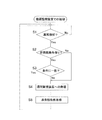
図6に示すように、異常検知部12aにより空気調和装置50における異常が検出されると(ステップS1)、異常識別部12eは非発報条件記憶領域13cに非発報条件が記憶されているか否かを確認する(ステップS2)。非発報条件が記憶されていた場合、異常識別部12eは、異常検知部12aが検知した異常が非発報条件記憶領域13cに記憶されている非発報条件に一致するか否かを判断する(ステップS3)。ここで、検知された異常が非発報条件に一致しない場合は、遠隔監視装置20へ異常発報を行い(ステップS4)、非発報条件に一致する場合は、異常発報を行わない。また、ステップS2で、非発報条件が記憶されていないと判断された場合は、ステップS4に進み遠隔監視装置20への異常発報を行う。遠隔監視装置20へ異常発報を行うと、その後遠隔監視装置20から送信される非発報条件を取得する(ステップS5)。
A. Control Flow in
B.遠隔監視装置20における制御の流れ
次に、図7を用いて、遠隔監視装置20における制御の流れを説明する。
B. Control Flow in
遠隔監視装置20において異常発報が受信されると(ステップS11)、非発報条件生成部25bは非発報条件記憶領域24cに非発報条件が記憶されているか否か確認する(ステップS12)。非発報条件が記憶されていた場合、非発報条件生成部25bは非発報条件を更新する(ステップS13)。ステップS12において非発報条件が記憶されていないと確認された場合は、非発報条件生成部25bは非発報条件を生成する(ステップS14)。ステップS13またはステップS14において非発報条件が更新または生成されると、非発報条件送信部25cが遠隔監視通信部21を経由し当該非発報条件を機器監視装置10に送信する(ステップS15)。
When the
〈特徴〉
(1)本発明に係る遠隔監視システム100では、機器監視装置10から遠隔監視装置20に発報される異常が、既に発報された異常のカテゴリおよび異常のレベルと比較される。検知された新たな異常と、既に発報された異常に基づく非発報条件で示される異常が同一カテゴリであり、かつ同一レベルの異常であった場合には、機器監視装置10は遠隔監視装置20への異常発報を行わない。これにより、機器監視装置10から遠隔監視装置20へ送信される異常発報の量を減らすことができるため、遠隔監視装置20において、早急に対応が必要な異常を容易に判別することができる。
<Characteristic>
(1) In the
さらに、本実施形態に係る遠隔監視システム100では、機器監視装置10で検出された空気調和装置50の異常が遠隔監視装置20に送信されると、当該異常に関する情報が管理者端末31および/または販売店端末30に自動的に送信される。そのため、遠隔監視装置20で受信する異常発報を制限することにより、管理者端末31および/または販売店端末30に送信される異常に関する情報も制限するため、各端末30,31においても異常に対応する煩雑さを解消することができる。
Furthermore, in the
(2)また、本実施形態に係る機器監視装置10は、異常発報時に遠隔監視装置20で生成された非発報条件を取得する。この非発報条件は異常のカテゴリおよび異常のレベルに応じて異なる更新時間を有する。また、この更新時間は、遠隔管理センター2の管理者が顧客の意向を反映させて設定することができる。したがって、即座に対応すべき異常であって常時把握したい異常と、承知済みの異常であり一定期間は確認する必要がない異常との更新時間を変更することにより、顧客の要望に適切に対応することができる。
(2) Moreover, the
(3)さらに、本実施形態に係る遠隔監視システム100では、空気調和装置50の運転状況の履歴である運転履歴と、異常の変化点の履歴である変化点履歴とが機器監視装置10から遠隔監視装置20に定期的に送信される。したがって、機器監視装置10で検知した異常の全てを遠隔監視装置20へ通報していない本実施形態に係る遠隔監視システム100であっても、遠隔監視センター2において空気調和装置50の状況を効率よく把握することができる。
(3) Furthermore, in the
〈変更例〉
(1)上記実施形態において、機器監視装置10の管理対象となる機器は、空気調和装置50以外の設備機器であってもよい。例えば、電源設備、給排水装置、昇降機、照明装置、防災装置、防犯装置等であってもよく、また、複数の種類の機器が組み合わせられたものであってもよい。
<Example of change>
(1) In the above embodiment, the device to be managed by the
(2)本実施形態では、機器監視装置10と、遠隔監視装置20と、販売店端末30と、管理者端末31とが、インターネット回線以外の回線で接続されていてもよい。例えば、電話回線で接続されていてもよい。さらに、販売店端末30および管理者端末31は、機器監視装置10および遠隔管理装置20と接続されていなくてもよい。
(2) In the present embodiment, the
(3)本実施形態に係る遠隔監視システム100では、機器監視装置10からの異常発報が、遠隔監視装置20から送信される非発報条件に基づいて行われ、非発報条件で示される異常と同一のカテゴリおよび同一のレベルの場合に、機器監視装置10からの異常発報が制限されたが、非発報条件で示される異常と同一レベルに限らず、非発報条件で示される異常と同一レベルおよびそれより低いレベルの異常発報を制限するように設定してもよい。それにより、遠隔監視装置20で受信される異常発報の量をさらに制限することができ、空気調和装置50の運転状況の把握および異常に対する対応がより容易にできる。さらに、異常のレベルが高い場合であって、早急な対応が必要な異常については、常に通報を必要とするように設定してもよい。
(3) In the
(4)また、図5では、異常のレベルが「高、中、低」に分類されたが、異常のレベルの分類はこれらに限られず遠隔監視センター2の管理者の任意で決定してもよい。例えば、軽微、重要の2段階に分類してもよい。
(4) In FIG. 5, the abnormality level is classified as “high, medium, low”. However, the classification of the abnormality level is not limited to these and may be arbitrarily determined by the administrator of the
〈他の実施形態〉
以上、本発明の実施形態について図面に基づいて説明したが、具体的な構成は、これらの実施形態に限られるものではなく、発明の要旨を逸脱しない範囲で変更可能である。
<Other embodiments>
As mentioned above, although embodiment of this invention was described based on drawing, a specific structure is not restricted to these embodiment, It can change in the range which does not deviate from the summary of invention.
本発明は、機器監視装置から遠隔監視装置に対する異常発報の量を減少させ、早急な対応が必要な異常に係る情報を容易に判別することができる機器監視装置および遠隔監視システムとして有用である。 INDUSTRIAL APPLICABILITY The present invention is useful as a device monitoring device and a remote monitoring system that can reduce the amount of abnormality reporting from a device monitoring device to a remote monitoring device and can easily determine information related to an abnormality that requires immediate action. .
1 物件
2 遠隔監視センター
10 機器監視装置
20 遠隔監視装置
50 空気調和装置
100 遠隔監視システム
1
Claims (6)
前記機器の遠隔に配置され、前記機器監視装置から前記運転状況に関する情報を受信する遠隔監視装置(20)と、
を備える遠隔監視システム(100)であって、
前記機器監視装置は、
前記機器で発生した異常を検知する異常検知部(12a)と、
前記遠隔監視装置への異常発報を制限する条件である非発報条件であって、前記遠隔監視装置から送られる前記非発報条件、に示される異常のカテゴリおよび異常のレベルに基づき、前記異常検知部によって検知された前記異常を識別する異常識別部(12e)と、
前記異常識別部の識別した結果に基づいて、前記遠隔監視装置に対する前記異常の通報である異常発報を行う異常発報部(12d)と
を有し、
前記遠隔監視装置は、
前記異常発報を受信する異常発報受信部(25a)と、
前記異常発報に係る異常のカテゴリおよび異常のレベルに基づき、前記非発報条件を生成し更新する非発報条件生成部(25b)と、
前記非発報条件を前記機器監視装置に送信する非発報条件送信部(25c)と、
を有する遠隔監視システム。 A device monitoring device (10) for monitoring the operating status of the device;
A remote monitoring device (20) disposed remotely from the device and receiving information on the driving situation from the device monitoring device;
A remote monitoring system (100) comprising:
The device monitoring device is
An anomaly detector (12a) for detecting an anomaly occurring in the device ;
A non-reporting condition that is a condition for limiting the abnormal reporting to the remote monitoring device, based on the category and level of the abnormality indicated in the non-reporting condition sent from the remote monitoring device, An abnormality identification unit (12e) for identifying the abnormality detected by the abnormality detection unit;
On the basis of the abnormality recognizing unit of the identification result, have a said abnormality alarm unit that performs a notification in which abnormal alarm of abnormality (12d) for the remote monitoring device,
The remote monitoring device is
An abnormal report receiving unit (25a) for receiving the abnormal report;
A non-reporting condition generation unit (25b) that generates and updates the non-reporting condition based on an abnormality category and an abnormality level related to the abnormal reporting;
A non-reporting condition transmitting unit (25c) for transmitting the non-reporting condition to the device monitoring device ;
Having a remote monitoring system.
請求項1に記載の遠隔監視システム。The remote monitoring system according to claim 1.
請求項2に記載の遠隔監視システム。 The abnormality identification unit compares the newly detected abnormality category and abnormality level with the newly detected abnormality, and the abnormality category and abnormality level indicated in the non-reporting condition .
The remote monitoring system according to claim 2 .
請求項3に記載の遠隔監視システム。 The abnormality reporting unit includes the abnormality in which the new abnormality category is the same as the abnormality category indicated in the non-reporting condition , and the new abnormality level is included in the non-reporting condition. At least when the one case when the level of the same and the lower than the abnormal level indicated in the non-alarm condition, the remote according to claim 3 is not performed the abnormality alarm for the remote monitoring device Monitoring system.
請求項1から4のいずれかに記載の遠隔監視システム。 The apparatus further includes a periodic notification unit (12c) that periodically transmits at least one of an operation history that is a history of the operation status of the device and a change point history that is a history of the abnormal change point to the remote monitoring device. ,
The remote monitoring system according to any one of claims 1 to 4 .
請求項5に記載の遠隔監視システム。 The remote monitoring device automatically transmits the abnormality information to at least one of an administrator of the device and a store when the abnormality notification is received by the abnormality notification receiving unit ( 25d)
The remote monitoring system according to claim 5 .
Priority Applications (8)
| Application Number | Priority Date | Filing Date | Title |
|---|---|---|---|
| JP2007250332A JP4337923B2 (en) | 2007-09-27 | 2007-09-27 | Device monitoring device and remote monitoring system |
| PCT/JP2008/002655 WO2009041039A1 (en) | 2007-09-27 | 2008-09-25 | Device monitor and remote monitoring system |
| ES08834531T ES2709900T3 (en) | 2007-09-27 | 2008-09-25 | Device monitor and remote monitoring system |
| KR1020107008207A KR101097720B1 (en) | 2007-09-27 | 2008-09-25 | Remote Monitoring System |
| CN2008801089320A CN101809373B (en) | 2007-09-27 | 2008-09-25 | Device monitor and remote monitoring system |
| EP08834531.9A EP2208944B1 (en) | 2007-09-27 | 2008-09-25 | Device monitor and remote monitoring system |
| AU2008305923A AU2008305923B8 (en) | 2007-09-27 | 2008-09-25 | Equipment Monitoring Device and Remote Monitoring System |
| US12/678,505 US8326578B2 (en) | 2007-09-27 | 2008-09-25 | Equipment monitoring device and remote monitoring system |
Applications Claiming Priority (1)
| Application Number | Priority Date | Filing Date | Title |
|---|---|---|---|
| JP2007250332A JP4337923B2 (en) | 2007-09-27 | 2007-09-27 | Device monitoring device and remote monitoring system |
Publications (2)
| Publication Number | Publication Date |
|---|---|
| JP2009079843A JP2009079843A (en) | 2009-04-16 |
| JP4337923B2 true JP4337923B2 (en) | 2009-09-30 |
Family
ID=40510944
Family Applications (1)
| Application Number | Title | Priority Date | Filing Date |
|---|---|---|---|
| JP2007250332A Active JP4337923B2 (en) | 2007-09-27 | 2007-09-27 | Device monitoring device and remote monitoring system |
Country Status (8)
| Country | Link |
|---|---|
| US (1) | US8326578B2 (en) |
| EP (1) | EP2208944B1 (en) |
| JP (1) | JP4337923B2 (en) |
| KR (1) | KR101097720B1 (en) |
| CN (1) | CN101809373B (en) |
| AU (1) | AU2008305923B8 (en) |
| ES (1) | ES2709900T3 (en) |
| WO (1) | WO2009041039A1 (en) |
Families Citing this family (19)
| Publication number | Priority date | Publication date | Assignee | Title |
|---|---|---|---|---|
| JP4265683B1 (en) * | 2007-10-31 | 2009-05-20 | ダイキン工業株式会社 | Remote monitoring system |
| JP2011003007A (en) * | 2009-06-18 | 2011-01-06 | Yamatake Corp | Device and method for controlling facilities |
| EP2927613B1 (en) * | 2012-11-30 | 2019-09-04 | Mitsubishi Electric Corporation | Facility equipment operation device, facility equipment operation system, facility equipment operation method, and program |
| US9189644B2 (en) | 2012-12-20 | 2015-11-17 | Bank Of America Corporation | Access requests at IAM system implementing IAM data model |
| US9529629B2 (en) * | 2012-12-20 | 2016-12-27 | Bank Of America Corporation | Computing resource inventory system |
| KR101721814B1 (en) * | 2013-06-26 | 2017-03-30 | 미쓰비시덴키 가부시키가이샤 | Remote unit and remote unit abnormality determining method |
| KR101356081B1 (en) * | 2013-07-11 | 2014-01-28 | 한국과학기기공업협동조합 | Scientific instruments management system |
| CN104033992A (en) * | 2014-06-06 | 2014-09-10 | 广东美的暖通设备有限公司 | VRF (Variable Refrigerant Flow)air-conditioner fault handling method and air-conditioner |
| CN104898639B (en) * | 2015-04-03 | 2018-08-07 | 珠海格力电器股份有限公司 | System for equipment state detection and control method |
| CN107842975A (en) * | 2016-09-20 | 2018-03-27 | 中国电信股份有限公司 | Special air conditioning for device room running status determines method, apparatus, system and user terminal |
| JP6899177B2 (en) * | 2016-10-27 | 2021-07-07 | ホーチキ株式会社 | Tunnel disaster prevention system |
| JP7111944B2 (en) * | 2017-12-13 | 2022-08-03 | ダイキン工業株式会社 | Air-conditioning system, remote control device, and method for storing operation data history of air-conditioner |
| JP7068819B2 (en) * | 2017-12-28 | 2022-05-17 | アズビル株式会社 | Facility monitoring device and facility monitoring method |
| CN110086697A (en) * | 2019-04-29 | 2019-08-02 | 广东美的制冷设备有限公司 | Household electrical appliances fault handling method and device |
| JP7397276B2 (en) * | 2019-05-21 | 2023-12-13 | ダイキン工業株式会社 | equipment management system |
| WO2020245933A1 (en) * | 2019-06-05 | 2020-12-10 | 三菱電機株式会社 | Air-conditioning and cooling equipment management apparatus |
| JP7545818B2 (en) * | 2020-06-03 | 2024-09-05 | 日立グローバルライフソリューションズ株式会社 | Abnormality diagnosis device and abnormality diagnosis method |
| CN113324313A (en) * | 2021-05-17 | 2021-08-31 | Tcl空调器(中山)有限公司 | Method for reporting case by using air conditioner, case reporting system of air conditioner, air conditioner and storage medium |
| CN114139745A (en) * | 2021-12-01 | 2022-03-04 | 北京磁浮有限公司 | Information processing and control method, device and terminal for rail transit power supply and distribution facility |
Family Cites Families (5)
| Publication number | Priority date | Publication date | Assignee | Title |
|---|---|---|---|---|
| JP3757504B2 (en) * | 1996-12-12 | 2006-03-22 | 三菱電機株式会社 | Cooling device remote monitoring system |
| JP3521843B2 (en) * | 2000-04-20 | 2004-04-26 | ダイキン工業株式会社 | Air conditioner monitoring system |
| JP2003166745A (en) * | 2001-11-29 | 2003-06-13 | Daikin Ind Ltd | Remote monitor device of air conditioner |
| CN1256550C (en) | 2004-03-25 | 2006-05-17 | 上海交通大学 | On-line fault diagnosis system for centarl air conditioner water system temp and flow sensor |
| US7188482B2 (en) * | 2004-08-27 | 2007-03-13 | Carrier Corporation | Fault diagnostics and prognostics based on distance fault classifiers |
-
2007
- 2007-09-27 JP JP2007250332A patent/JP4337923B2/en active Active
-
2008
- 2008-09-25 US US12/678,505 patent/US8326578B2/en active Active
- 2008-09-25 ES ES08834531T patent/ES2709900T3/en active Active
- 2008-09-25 CN CN2008801089320A patent/CN101809373B/en not_active Expired - Fee Related
- 2008-09-25 KR KR1020107008207A patent/KR101097720B1/en not_active IP Right Cessation
- 2008-09-25 AU AU2008305923A patent/AU2008305923B8/en not_active Ceased
- 2008-09-25 EP EP08834531.9A patent/EP2208944B1/en active Active
- 2008-09-25 WO PCT/JP2008/002655 patent/WO2009041039A1/en active Application Filing
Also Published As
| Publication number | Publication date |
|---|---|
| US8326578B2 (en) | 2012-12-04 |
| JP2009079843A (en) | 2009-04-16 |
| CN101809373A (en) | 2010-08-18 |
| KR20100068441A (en) | 2010-06-23 |
| KR101097720B1 (en) | 2011-12-23 |
| CN101809373B (en) | 2012-10-17 |
| AU2008305923A1 (en) | 2009-04-02 |
| EP2208944B1 (en) | 2018-11-07 |
| EP2208944A1 (en) | 2010-07-21 |
| ES2709900T3 (en) | 2019-04-22 |
| WO2009041039A1 (en) | 2009-04-02 |
| US20100204958A1 (en) | 2010-08-12 |
| EP2208944A4 (en) | 2015-02-18 |
| AU2008305923B8 (en) | 2011-03-31 |
| AU2008305923B2 (en) | 2011-03-17 |
Similar Documents
| Publication | Publication Date | Title |
|---|---|---|
| JP4337923B2 (en) | Device monitoring device and remote monitoring system | |
| US7295896B2 (en) | Automated part procurement and service dispatch | |
| US6955302B2 (en) | Remote monitoring diagnostics | |
| KR101259803B1 (en) | Unifying Control System for Multi-Airconditioner and Error control method thereof | |
| US11132892B1 (en) | Abberation detection technology | |
| CN113455014B (en) | Device management system | |
| WO2008004515A1 (en) | Control apparatus | |
| JP2008217229A (en) | Equipment management device and equipment management system | |
| KR100697079B1 (en) | Multi-Airconditioner Center Control System and Error Report Method thereof | |
| JP2015188421A (en) | remote monitoring system | |
| JP4765798B2 (en) | Diagnostic device and air conditioning management device | |
| JP4827780B2 (en) | Air conditioning control system | |
| AU2008239134B8 (en) | Group management apparatus and group management system | |
| JP2009059270A (en) | Equipment monitoring device, comprehensive management device, and abnormality warning destination changing system | |
| JP2011237935A (en) | Facility equipment management system | |
| JP2008051357A (en) | Remote management system and remote management device | |
| JP2009222321A (en) | Remote monitoring system | |
| JP2008262359A (en) | Group management device, group management program, and group management system | |
| AU2010201357B2 (en) | Alarm and diagnostics system and method for a distributed-architecture heating, ventilation and air conditioning network |
Legal Events
| Date | Code | Title | Description |
|---|---|---|---|
| A521 | Request for written amendment filed |
Free format text: JAPANESE INTERMEDIATE CODE: A523 Effective date: 20090129 |
|
| TRDD | Decision of grant or rejection written | ||
| A01 | Written decision to grant a patent or to grant a registration (utility model) |
Free format text: JAPANESE INTERMEDIATE CODE: A01 Effective date: 20090609 |
|
| A01 | Written decision to grant a patent or to grant a registration (utility model) |
Free format text: JAPANESE INTERMEDIATE CODE: A01 |
|
| A61 | First payment of annual fees (during grant procedure) |
Free format text: JAPANESE INTERMEDIATE CODE: A61 Effective date: 20090622 |
|
| R151 | Written notification of patent or utility model registration |
Ref document number: 4337923 Country of ref document: JP Free format text: JAPANESE INTERMEDIATE CODE: R151 |
|
| FPAY | Renewal fee payment (event date is renewal date of database) |
Free format text: PAYMENT UNTIL: 20120710 Year of fee payment: 3 |
|
| FPAY | Renewal fee payment (event date is renewal date of database) |
Free format text: PAYMENT UNTIL: 20120710 Year of fee payment: 3 |
|
| FPAY | Renewal fee payment (event date is renewal date of database) |
Free format text: PAYMENT UNTIL: 20130710 Year of fee payment: 4 |