EP2208885A2 - Turbine blade and method of fabricating the same - Google Patents
Turbine blade and method of fabricating the same Download PDFInfo
- Publication number
- EP2208885A2 EP2208885A2 EP09177435A EP09177435A EP2208885A2 EP 2208885 A2 EP2208885 A2 EP 2208885A2 EP 09177435 A EP09177435 A EP 09177435A EP 09177435 A EP09177435 A EP 09177435A EP 2208885 A2 EP2208885 A2 EP 2208885A2
- Authority
- EP
- European Patent Office
- Prior art keywords
- joint
- base
- turbine blade
- blade
- region
- Prior art date
- Legal status (The legal status is an assumption and is not a legal conclusion. Google has not performed a legal analysis and makes no representation as to the accuracy of the status listed.)
- Withdrawn
Links
- 238000004519 manufacturing process Methods 0.000 title description 3
- 230000013011 mating Effects 0.000 claims abstract description 20
- 239000011521 glass Substances 0.000 claims description 18
- 150000001721 carbon Chemical class 0.000 claims description 4
- 230000002093 peripheral effect Effects 0.000 claims description 3
- 238000000034 method Methods 0.000 description 14
- 238000003780 insertion Methods 0.000 description 4
- 230000037431 insertion Effects 0.000 description 4
- 239000000853 adhesive Substances 0.000 description 3
- 230000001070 adhesive effect Effects 0.000 description 3
- 239000006260 foam Substances 0.000 description 3
- 239000002131 composite material Substances 0.000 description 2
- 238000003754 machining Methods 0.000 description 2
- 238000012986 modification Methods 0.000 description 2
- 230000004048 modification Effects 0.000 description 2
- 230000008719 thickening Effects 0.000 description 2
- 239000002023 wood Substances 0.000 description 2
- OKTJSMMVPCPJKN-UHFFFAOYSA-N Carbon Chemical compound [C] OKTJSMMVPCPJKN-UHFFFAOYSA-N 0.000 description 1
- 239000004593 Epoxy Substances 0.000 description 1
- 240000007182 Ochroma pyramidale Species 0.000 description 1
- 238000005452 bending Methods 0.000 description 1
- 229910052799 carbon Inorganic materials 0.000 description 1
- 238000007796 conventional method Methods 0.000 description 1
- 239000003733 fiber-reinforced composite Substances 0.000 description 1
- 238000001802 infusion Methods 0.000 description 1
- 239000000463 material Substances 0.000 description 1
- 239000011347 resin Substances 0.000 description 1
- 229920005989 resin Polymers 0.000 description 1
- 238000012549 training Methods 0.000 description 1
Images



Classifications
-
- F—MECHANICAL ENGINEERING; LIGHTING; HEATING; WEAPONS; BLASTING
- F03—MACHINES OR ENGINES FOR LIQUIDS; WIND, SPRING, OR WEIGHT MOTORS; PRODUCING MECHANICAL POWER OR A REACTIVE PROPULSIVE THRUST, NOT OTHERWISE PROVIDED FOR
- F03D—WIND MOTORS
- F03D1/00—Wind motors with rotation axis substantially parallel to the air flow entering the rotor
- F03D1/06—Rotors
- F03D1/065—Rotors characterised by their construction elements
- F03D1/0675—Rotors characterised by their construction elements of the blades
-
- F—MECHANICAL ENGINEERING; LIGHTING; HEATING; WEAPONS; BLASTING
- F05—INDEXING SCHEMES RELATING TO ENGINES OR PUMPS IN VARIOUS SUBCLASSES OF CLASSES F01-F04
- F05B—INDEXING SCHEME RELATING TO WIND, SPRING, WEIGHT, INERTIA OR LIKE MOTORS, TO MACHINES OR ENGINES FOR LIQUIDS COVERED BY SUBCLASSES F03B, F03D AND F03G
- F05B2240/00—Components
- F05B2240/20—Rotors
- F05B2240/30—Characteristics of rotor blades, i.e. of any element transforming dynamic fluid energy to or from rotational energy and being attached to a rotor
-
- F—MECHANICAL ENGINEERING; LIGHTING; HEATING; WEAPONS; BLASTING
- F05—INDEXING SCHEMES RELATING TO ENGINES OR PUMPS IN VARIOUS SUBCLASSES OF CLASSES F01-F04
- F05B—INDEXING SCHEME RELATING TO WIND, SPRING, WEIGHT, INERTIA OR LIKE MOTORS, TO MACHINES OR ENGINES FOR LIQUIDS COVERED BY SUBCLASSES F03B, F03D AND F03G
- F05B2240/00—Components
- F05B2240/20—Rotors
- F05B2240/30—Characteristics of rotor blades, i.e. of any element transforming dynamic fluid energy to or from rotational energy and being attached to a rotor
- F05B2240/302—Segmented or sectional blades
-
- Y—GENERAL TAGGING OF NEW TECHNOLOGICAL DEVELOPMENTS; GENERAL TAGGING OF CROSS-SECTIONAL TECHNOLOGIES SPANNING OVER SEVERAL SECTIONS OF THE IPC; TECHNICAL SUBJECTS COVERED BY FORMER USPC CROSS-REFERENCE ART COLLECTIONS [XRACs] AND DIGESTS
- Y02—TECHNOLOGIES OR APPLICATIONS FOR MITIGATION OR ADAPTATION AGAINST CLIMATE CHANGE
- Y02E—REDUCTION OF GREENHOUSE GAS [GHG] EMISSIONS, RELATED TO ENERGY GENERATION, TRANSMISSION OR DISTRIBUTION
- Y02E10/00—Energy generation through renewable energy sources
- Y02E10/70—Wind energy
- Y02E10/72—Wind turbines with rotation axis in wind direction
-
- Y—GENERAL TAGGING OF NEW TECHNOLOGICAL DEVELOPMENTS; GENERAL TAGGING OF CROSS-SECTIONAL TECHNOLOGIES SPANNING OVER SEVERAL SECTIONS OF THE IPC; TECHNICAL SUBJECTS COVERED BY FORMER USPC CROSS-REFERENCE ART COLLECTIONS [XRACs] AND DIGESTS
- Y10—TECHNICAL SUBJECTS COVERED BY FORMER USPC
- Y10T—TECHNICAL SUBJECTS COVERED BY FORMER US CLASSIFICATION
- Y10T29/00—Metal working
- Y10T29/49—Method of mechanical manufacture
- Y10T29/49316—Impeller making
- Y10T29/49336—Blade making
- Y10T29/49337—Composite blade
Definitions
- the invention relates generally to turbine blades, and, more particularly, to multiple-piece turbine blades and methods of fabricating the turbine blades.
- Turbine blades such as those used for wind turbines usually have large sizes. Shipment of a large blade from where it was made to where it will be assembled is inconvenient and costly.
- a turbine blade in accordance with an embodiment disclosed herein, includes at least two blade segments.
- Each blade segment includes first and second shells joined together, a base region, at least one joint region including a mating face.
- Each of the first and second shells includes an outer skin, a base spar cap attached to an inner surface of the outer skin in the base region, a joint spar cap attached to the inner surface of the outer skin in the joint region and adjacent to at least a portion of the base spar cap.
- the joint spar cap includes holes in the mating face of the joint region.
- the turbine blade further includes fasteners within the holes for securing the at least two blade segments together.
- a blade segment in accordance with another embodiment disclosed herein, includes first and second shells joined together, a base region, and at least one joint region including a mating face.
- Each of the first and second shells further includes an outer skin, a base spar cap attached to an inner surface of the outer skin in the base region, and a joint spar cap attached to the inner surface of the outer skin in the joint region and respectively adjacent to at least a portion of a corresponding base spar cap.
- the joint spar cap includes holes in the mating face of the joint region for insertion of fasteners.
- a method of fabricating a blade segment includes providing first and second outer skins of the first and second shells; providing joint spar caps respectively on inner surfaces of the first and second outer skins in joint regions of the first and second outer skins; positioning base spar caps respectively on each inner surface of the first and second outer skins in base regions of the first and second outer skins and adjacent to the joint spar caps; positioning at least one shear web between the pair of base spar caps and between the pair of joint spar caps; attaching the first and second shells; and providing holes in the joint spar caps in mating faces of the joint regions for insertion of fasteners.
- embodiments of the present invention include turbine blades and methods for fabricating turbine blades.
- turbine blades refers to blades used in various applications such as, but not limited to, wind turbines and aircraft systems.
- FIGs. 1-7 show embodiments of the invention used in a wind turbine system 10.
- wind turbine system 10 includes a rotor 14 and several blades 12.
- Each blade 12 includes at least first and second blade segments 16 and 18.
- the term "outboard” means farther from rotor 14, and "inboard” means closer to rotor 14.
- first blade segment 16 is an inboard blade segment
- second blade segment 18 is an outboard blade segment.
- the blades 12 are mounted atop a tower 20.
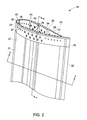
- FIG. 2 is an exemplary perspective view of inboard blade segment 16, which includes a base region 22, a joint region 24, a pressure side shell 23, and a suction side shell 21.
- Each shell includes an outer skin 26, 27, a core 36, 37, an inner skin 44, 45, and spar caps which are shown in more detail below with respect to FIG. 4 .
- Joint region 24 includes a mating face 28 for engaging with outboard blade segment 18.
- Joint region 24 is formed in a shape of an airfoil section and has a leading edge 30 and a training edge 32.
- outer skin 26 and 27 is made from glass reinforced composites such as, for example biaxial glass, uniaxial glass, or triaxial glass, or any combination of thereof.
- cores 36 and 37 comprise wood, for example, balsa, or foam, or a combination of both.
- inner skin 44, 45 is formed from glass reinforced composites such as, for example, biaxial glass layers.
- joint region 24 has a stepped inner surface, and includes joint spar caps 34 which have larger thicknesses than cores 36 and 37.
- joint spar cap 34 of joint region 24 comprises triaxial glass layers.
- One or more longitudinal crossbeams 38 are disposed within joint region 24 and between upper and lower joint spar caps 34.
- Shear web 38 is adapted to withstand aerodynamic shear loading on blade 12.
- shear web 38 is made from foam strengthened with biaxial glass.
- a plurality of longitudinal holes 40 extend into mating face 28 in the longitudinal direction.
- holes 40 in joint spar caps 34 have a larger diameter than holes 40 in cores 36 and 37.
- Joint region 24 may additionally define a plurality of access slots 42 along an outer and/or inner periphery thereof. Each access slot 42 extends at least partially through joint region 24 and communicates with a corresponding hole 40.
- two rows of access slots 42 are respectively defined in upper and lower joint spar caps 34, and the two rows of access slots 42 are staggered in the longitudinal direction.
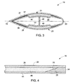
- FIG. 3 is a cross-sectional view of base region 22 of inboard blade segment 16 along line 3-3 of FIG. 2 .
- Base region 22 includes longitudinal bending load bearing structures or base spar caps 46 between inboard outer skin 26, 27 and inner skin 44, 45.
- base spar caps 46 are formed from continuous fiber reinforced composites such as carbon composites.
- the base spar caps 46 may be formed of glass or carbon.
- One or more shear webs 48, 38 to be used for withstanding aerodynamic shear loading on the wind turbine blade 12 are disposed within the airfoil section between the base spar caps 46.
- shear webs 48 and 38 of base region 22 and joint region 24 are separately made and joined with each other to extend along a full length of the inboard blade segment 16.
- shear webs 48 and 38 are portions of one integral shear web.
- FIG. 4 is an illustrative cross-sectional view of one embodiment of inboard blade segment 16 along line 4-4 of FIG. 2 .
- base spar caps 46 of base region 22 and upper and lower joint spar caps 34 of joint region 24 respectively have a first and a second tapered edge 33 and 35 engaging with each other. With this embodiment, a load on base spar caps 46 can be transferred to the joint spar caps 34 of the joint region 24.
- First and second tapered edges 33 and 35 in FIG. 4 are very exaggerated for purposes of illustration and are not drawn to scale.
- an exemplary process of fabricating a pressure side shell 23 of inboard blade segment 16 includes providing an outer skin 26 for example, laying up a plurality of biaxial glass layers.
- joint spar cap 34 is provided on an inner surface of outer skin 26 in joint region of pressure side shell 23.
- joint spar cap 34 is formed by thickening outer skin 26 at joint region 24 with triaxial glass layers.
- the triaxial glass layers are designed to have different length and width, so when they are laid up, a second tapered edge 35 is formed.
- the outer shell is molded, and joint spar cap 34 is integrally molded together with the outer shell.
- Base spar cap 46 is positioned on the inner surface of outer skin 26 in base region 22 of pressure side shell 23 adjacent to joint spar cap 34. As discussed above, in one embodiment, base spar cap 46 has a first tapered edge 33 to engage with second tapered edge 35 of joint spar cap 34. In one embodiment, the first and second tapered edges 33 and 35 are cured together after base spar cap 46 is properly positioned.
- a core 36 ( FIGs. 2 and 3 ), comprising a material such as wood or foam, is laid on non-spar cap areas of outer skin 26.
- the process of producing pressure side shell 23 of inboard blade segment 16 further includes laying an inner skin 44.
- inner skin 44 includes biaxial glass layers.
- Shear web 48 ( FIG. 3 ) is positioned on inner skin 44 and adhered thereto.
- a suction side shell 21 of the inboard blade segment 16 is produced with one fabricating example being similar to the process of pressure side shell 23 described above.
- the suction side and pressure side shells 21, 23 are attached to each other in any structurally appropriate matter with one example being by adhesive.
- holes 40 and access slots 42 are machined in joint region 24 after suction side and pressure side shells 26, 27 are assembled together. In another embodiment, machining of holes 40 and access slots 42 can be performed immediately after joint spar cap 34 is produced. In still another embodiment, machining holes 40 and access slots 42 can be performed after the inner skin 44, 45 is laid on.
- FIG. 5 illustrates a perspective view of outboard blade segment 18 which may be fabricated in a similar process as inboard blade segment 16 described above and may have a similar structure as that of inboard blade segment 16.
- Outboard blade segment 18 has a mating face 50 adapted for engaging with inboard blade segment 16.
- a plurality of longitudinal holes 52 extend from mating face 50 into outboard blade segment 18, in the longitudinal direction. Holes 52 are respectively in alignment with holes 40 of inboard blade segment 16 when assembling the inboard and outboard blade segments 16 and 8 together.
- Outboard blade segment 18 defines a plurality of access slots 54 along a periphery direction, and each access slot 54 communicates with a corresponding hole 52.
- Inboard and outboard blade segments 16 and 18 can be manufactured in the same or different factories.
- inboard and outboard blade segments 16 and 18 may be secured together as shown in FIG. 6 .
- the securing is accomplished with a T-bolt connection.
- a plurality of T-bolts 56 may be pre-attached to one of the inboard and outboard blade segments 16 and 18.
- T-bolts 56 may be pre-assembled to outboard blade segment 18 as shown in FIG. 5 .
- each T-bolt 56 includes a longitudinal stud 58 with opposite thread ends 60 and 62 (inboard and outboard thread ends) for engaging with barrel nuts 64 and 66.
- outboard thread end 60 of each T-bolt 56 is secured in outboard blade segment 18 by a corresponding barrel nut 66 before being shipped, and, after shipping, inboard thread end 62 of each T-bolt 56 is extended into a corresponding access slot 42 of inboard blade segment 16 through a corresponding inboard longitudinal hole 40.
- barrel nuts 66 are glued to outboard blade segment 18 through adhesive.
- the adhesive includes epoxy, an infusion resin, or combinations thereof.
Landscapes
- Engineering & Computer Science (AREA)
- Life Sciences & Earth Sciences (AREA)
- Sustainable Development (AREA)
- Sustainable Energy (AREA)
- Chemical & Material Sciences (AREA)
- Combustion & Propulsion (AREA)
- Mechanical Engineering (AREA)
- General Engineering & Computer Science (AREA)
- Wind Motors (AREA)
- Turbine Rotor Nozzle Sealing (AREA)
Abstract
Description
- The invention relates generally to turbine blades, and, more particularly, to multiple-piece turbine blades and methods of fabricating the turbine blades.
- Turbine blades such as those used for wind turbines usually have large sizes. Shipment of a large blade from where it was made to where it will be assembled is inconvenient and costly.
- There is a need in the art to ship the turbine blades in segments and then join the segments together at a remote assembly location. However, conventional methods for addressing this need often result in undesirable levels of complexity and expense. Accordingly, an improved joint system and a corresponding method are needed to address one or more of the foregoing issues.
- In accordance with an embodiment disclosed herein, a turbine blade is provided. The turbine blade includes at least two blade segments. Each blade segment includes first and second shells joined together, a base region, at least one joint region including a mating face. Each of the first and second shells includes an outer skin, a base spar cap attached to an inner surface of the outer skin in the base region, a joint spar cap attached to the inner surface of the outer skin in the joint region and adjacent to at least a portion of the base spar cap. The joint spar cap includes holes in the mating face of the joint region. The turbine blade further includes fasteners within the holes for securing the at least two blade segments together.
- In accordance with another embodiment disclosed herein, a blade segment is provided. The blade segment includes first and second shells joined together, a base region, and at least one joint region including a mating face. Each of the first and second shells further includes an outer skin, a base spar cap attached to an inner surface of the outer skin in the base region, and a joint spar cap attached to the inner surface of the outer skin in the joint region and respectively adjacent to at least a portion of a corresponding base spar cap. The joint spar cap includes holes in the mating face of the joint region for insertion of fasteners.
- In accordance with still another embodiment disclosed herein, a method of fabricating a blade segment is provided. The method includes providing first and second outer skins of the first and second shells; providing joint spar caps respectively on inner surfaces of the first and second outer skins in joint regions of the first and second outer skins; positioning base spar caps respectively on each inner surface of the first and second outer skins in base regions of the first and second outer skins and adjacent to the joint spar caps; positioning at least one shear web between the pair of base spar caps and between the pair of joint spar caps; attaching the first and second shells; and providing holes in the joint spar caps in mating faces of the joint regions for insertion of fasteners.
- Various features, aspects, and advantages of the present invention will become better understood when the following detailed description is read with reference to the accompanying drawings in which like characters represent like parts throughout the drawings, wherein:
-
FIG. 1 is a schematic illustration of a wind turbine including several blades. -
FIG. 2 is a perspective view of an inboard blade segment according to an embodiment of the invention. -
FIG. 3 is a cross-sectional view of the inboard blade segment along line 3-3 ofFIG. 2 . -
FIG. 4 is a partial cross-sectional view of the inboard blade segment along line 4-4 ofFIG. 2 . -
FIG. 5 is a perspective view of an outboard blade segment according to an embodiment of the invention. -
FIG. 6 illustrates the outboard and inboard blade segments engaging with each other. -
FIG. 7 is partial cross-sectional view of an assembly of the outboard and inboard blade segments along line 7-7 ofFIG. 6 according to certain embodiments of the invention. - As discussed in detail below, embodiments of the present invention include turbine blades and methods for fabricating turbine blades. As used herein, the term "turbine blades" refers to blades used in various applications such as, but not limited to, wind turbines and aircraft systems.
- As used herein, singular forms such as "a," "an," and "the" include plural referents unless the context clearly dictates otherwise. For example, although a two-segment blade is shown in the drawings for purposes of illustration, more segments may be included if desired.
-
FIGs. 1-7 show embodiments of the invention used in awind turbine system 10. Referring toFIG. 1 ,wind turbine system 10 includes arotor 14 andseveral blades 12. Eachblade 12 includes at least first andsecond blade segments rotor 14, and "inboard" means closer torotor 14. Thus, in the exemplary embodiment,first blade segment 16 is an inboard blade segment, andsecond blade segment 18 is an outboard blade segment. Theblades 12 are mounted atop atower 20. -
FIG. 2 is an exemplary perspective view ofinboard blade segment 16, which includes abase region 22, ajoint region 24, apressure side shell 23, and asuction side shell 21. Each shell includes anouter skin core inner skin FIG. 4 .Joint region 24 includes amating face 28 for engaging withoutboard blade segment 18.Joint region 24 is formed in a shape of an airfoil section and has a leadingedge 30 and atraining edge 32. In certain embodiments,outer skin cores inner skin - In one embodiment,
joint region 24 has a stepped inner surface, and includesjoint spar caps 34 which have larger thicknesses thancores joint spar cap 34 ofjoint region 24 comprises triaxial glass layers. - One or more
longitudinal crossbeams 38, also referred to as shear webs, are disposed withinjoint region 24 and between upper and lowerjoint spar caps 34.Shear web 38 is adapted to withstand aerodynamic shear loading onblade 12. In certain embodiments,shear web 38 is made from foam strengthened with biaxial glass. - A plurality of
longitudinal holes 40 extend intomating face 28 in the longitudinal direction. In the exemplary embodiment,holes 40 injoint spar caps 34 have a larger diameter thanholes 40 incores Joint region 24 may additionally define a plurality ofaccess slots 42 along an outer and/or inner periphery thereof. Eachaccess slot 42 extends at least partially throughjoint region 24 and communicates with acorresponding hole 40. In the exemplary embodiment, two rows ofaccess slots 42 are respectively defined in upper and lowerjoint spar caps 34, and the two rows ofaccess slots 42 are staggered in the longitudinal direction. -
FIG. 3 is a cross-sectional view ofbase region 22 ofinboard blade segment 16 along line 3-3 ofFIG. 2 .Base region 22 includes longitudinal bending load bearing structures orbase spar caps 46 between inboardouter skin inner skin base spar caps 46 are formed from continuous fiber reinforced composites such as carbon composites. In certain other embodiments, thebase spar caps 46 may be formed of glass or carbon. One ormore shear webs wind turbine blade 12 are disposed within the airfoil section between thebase spar caps 46. In one embodiment,shear webs base region 22 andjoint region 24 are separately made and joined with each other to extend along a full length of theinboard blade segment 16. In an alternative embodiment,shear webs -
FIG. 4 is an illustrative cross-sectional view of one embodiment ofinboard blade segment 16 along line 4-4 ofFIG. 2 . In this embodiment,base spar caps 46 ofbase region 22 and upper and lowerjoint spar caps 34 ofjoint region 24 respectively have a first and a secondtapered edge base spar caps 46 can be transferred to thejoint spar caps 34 of thejoint region 24. First and secondtapered edges FIG. 4 are very exaggerated for purposes of illustration and are not drawn to scale. - With continued reference to
FIG. 4 , an exemplary process of fabricating apressure side shell 23 ofinboard blade segment 16 includes providing anouter skin 26 for example, laying up a plurality of biaxial glass layers. - A
joint spar cap 34 is provided on an inner surface ofouter skin 26 in joint region ofpressure side shell 23. In one embodiment,joint spar cap 34 is formed by thickeningouter skin 26 atjoint region 24 with triaxial glass layers. In one embodiment, the triaxial glass layers are designed to have different length and width, so when they are laid up, a second taperededge 35 is formed. In another embodiment, the outer shell is molded, andjoint spar cap 34 is integrally molded together with the outer shell. -
Base spar cap 46 is positioned on the inner surface ofouter skin 26 inbase region 22 ofpressure side shell 23 adjacent tojoint spar cap 34. As discussed above, in one embodiment,base spar cap 46 has a first taperededge 33 to engage with second taperededge 35 ofjoint spar cap 34. In one embodiment, the first and secondtapered edges base spar cap 46 is properly positioned. A core 36 (FIGs. 2 and3 ), comprising a material such as wood or foam, is laid on non-spar cap areas ofouter skin 26. - In certain embodiments, the process of producing
pressure side shell 23 ofinboard blade segment 16 further includes laying aninner skin 44. For example, a joint of the first and secondtapered edges inner skin 44. In certain embodiments,inner skin 44 includes biaxial glass layers. - Shear web 48 (
FIG. 3 ) is positioned oninner skin 44 and adhered thereto. Asuction side shell 21 of theinboard blade segment 16 is produced with one fabricating example being similar to the process ofpressure side shell 23 described above. The suction side andpressure side shells - In one embodiment, holes 40 and
access slots 42 are machined injoint region 24 after suction side andpressure side shells holes 40 andaccess slots 42 can be performed immediately afterjoint spar cap 34 is produced. In still another embodiment, machining holes 40 andaccess slots 42 can be performed after theinner skin -
FIG. 5 illustrates a perspective view ofoutboard blade segment 18 which may be fabricated in a similar process asinboard blade segment 16 described above and may have a similar structure as that ofinboard blade segment 16.Outboard blade segment 18 has amating face 50 adapted for engaging withinboard blade segment 16. A plurality oflongitudinal holes 52 extend frommating face 50 intooutboard blade segment 18, in the longitudinal direction.Holes 52 are respectively in alignment withholes 40 ofinboard blade segment 16 when assembling the inboard andoutboard blade segments 16 and 8 together.Outboard blade segment 18 defines a plurality ofaccess slots 54 along a periphery direction, and eachaccess slot 54 communicates with a correspondinghole 52. Inboard andoutboard blade segments - After shipment, inboard and
outboard blade segments FIG. 6 . In one embodiment, the securing is accomplished with a T-bolt connection. In a more specific embodiment, a plurality of T-bolts 56 (shown inFIG. 5 ) may be pre-attached to one of the inboard andoutboard blade segments bolts 56 may be pre-assembled tooutboard blade segment 18 as shown inFIG. 5 . - Referring to
FIGs. 6 and7 , each T-bolt 56 includes alongitudinal stud 58 with opposite thread ends 60 and 62 (inboard and outboard thread ends) for engaging withbarrel nuts outboard thread end 60 of each T-bolt 56 is secured inoutboard blade segment 18 by acorresponding barrel nut 66 before being shipped, and, after shipping,inboard thread end 62 of each T-bolt 56 is extended into acorresponding access slot 42 ofinboard blade segment 16 through a corresponding inboardlongitudinal hole 40. In certain embodiments,barrel nuts 66 are glued tooutboard blade segment 18 through adhesive. In a non-limiting example, the adhesive includes epoxy, an infusion resin, or combinations thereof. - It is to be understood that not necessarily all such objects or advantages described above may be achieved in accordance with any particular embodiment. Thus, for example, those skilled in the art will recognize that the systems and techniques described herein may be embodied or carried out in a manner that achieves or optimizes one advantage or group of advantages as taught herein without necessarily achieving other objects or advantages as may be taught or suggested herein.
- Furthermore, the skilled artisan will recognize the interchangeability of various features from different embodiments. The various features described, as well as other known equivalents for each feature, can be mixed and matched by one of ordinary skill in this art to construct additional systems and techniques in accordance with principles of this disclosure.
- While only certain features of the invention have been illustrated and described herein, many modifications and changes will occur to those skilled in the art. It is, therefore, to be understood that the appended claims are intended to cover all such modifications and changes as fall within the true spirit of the invention.
- Various aspects and embodiments of the present invention are defined by the following numbered clauses:
- 1. A turbine blade comprising:
- at least two blade segments, each blade segment comprising first and second shells joined together, a base region, at least one joint region including a mating face, each of the first and second shells further comprising:
- an outer skin;
- a base spar cap attached to an inner surface of the outer skin in the base region;
- a joint spar cap attached to the inner surface of the outer skin in the joint region and adjacent to at least a portion of the base spar cap, wherein the joint spar cap includes holes in the mating face of the joint region; and
- fasteners within the holes securing the at least two blade segments together.
- 2. The turbine blade of clause 1, wherein each of the first and second shells further includes a core attached to the inner surface of the outer skin in core regions of the shell, and an inner skin attached to the base and joint spar caps and the core.
- 3. The turbine blade of any preceding clause, wherein each blade segment further includes at least one shear web.
- 4. The turbine blade of any preceding clause, wherein the at least one shear web is adjacent to the base spar caps in the base region, and where the at least one shear web is adjacent to the joint spar caps in the joint region.
- 5. The turbine blade of any preceding clause, wherein each base spar cap comprises a first tapered edge, each joint spar cap comprises a second tapered edge, and the first and second tapered edges face each other.
- 6. The turbine blade of any preceding clause, wherein the holes extend from the mating face along a longitudinal direction of the turbine blade.
- 7. The turbine blade of any preceding clause, wherein the joint region defines a plurality of peripheral access slots with each access slot communicating with a corresponding hole.
- 8. The turbine blade of any preceding clause, wherein the joint region defines at least two rows of staggered access slots.
- 9. The turbine blade of any preceding clause, wherein the spar caps comprise carbon composites.
- 10. The turbine blade of any preceding clause, wherein the joint spar cap comprises triaxial glass.
- 11. A blade segment comprising:
- first and second shells joined together, a base region, and at least one joint region including a mating face, each of the first and second shells further comprising:
- an outer skin,
- a base spar cap attached to an inner surface of the outer skin in the base region, and
- a joint spar cap attached to the inner surface of the outer skin in the joint region and respectively adjacent to at least a portion of a corresponding base spar cap,
- first and second shells joined together, a base region, and at least one joint region including a mating face, each of the first and second shells further comprising:
- 12. The blade segment of any preceding clause. wherein each of the first and second shells further comprises a core attached to the inner surface of the outer skin, and an inner skin attached to the base and joint spar caps and the core.
- 13. The blade segment of any preceding clause, wherein each base spar cap comprises a first tapered edge, each joint spar cap comprises a second tapered edge, and the first and second tapered edges face each other.
- 14. The blade segment of any preceding clause, wherein the joint region defines a plurality of peripheral access slots with each access slot communicating with a corresponding hole.
- 15. The blade segment of any preceding clause wherein the base spar caps comprise carbon composites, and the joint spar caps comprises triaxial glass.
- 16. A method of fabricating a blade segment comprising first and second shells, comprising:
- providing first and second outer skins of the first and second shells;
- providing joint spar caps respectively on inner surfaces of the first and second outer skins in joint regions of the first and second outer skins;
- positioning base spar caps respectively on each inner surface of the first and second outer skins in base regions of the first and second outer skins and adjacent to the joint spar caps;
- positioning at least one shear web between the pair of base spar caps and between the pair of joint spar caps;
- attaching the first and second shells; and
- providing holes in the joint spar caps in mating faces of the joint regions for insertion of fasteners.
- 17. The method of
clause 16 wherein providing joint spar caps comprises providing joint spar caps each having a tapered edge, wherein the base spar caps have tapered edges, and wherein the base spar caps are positioned such that the tapered edges of the joint spar caps and the spar caps are engaged. - 18. The method of
clause 16 or 17 further comprising, prior to attaching the first and second shells, attaching inner skins respectively to the base spar caps and the joint spar caps at least in the area of the tapered edges. - 19. The method of any of
clauses 16 to 18 wherein providing the joint spar caps comprises thickening the outer skin with triaxial glass layers in the joint region. - 20. The method of any of
clause 16 to 19, wherein the triaxial glass layers have different lengths and widths.
Claims (10)
- A turbine blade (12) comprising:at least two blade segments (16,18), each blade segment comprising first and second shells (21,23) joined together, a base region (22), at least one joint region (24) including a mating face (28), each of the first and second shells further comprising:an outer skin (26,27);a base spar cap (46) attached to an inner surface of the outer skin in the base region;a joint spar cap (34) attached to the inner surface of the outer skin in the joint region (24) and adjacent to at least a portion of the base spar cap (46), wherein the joint spar cap includes holes in the mating face of the joint region; andfasteners (64,66) within the holes securing the at least two blade segments (16,28) together.
- The turbine blade (12) of claim 1, wherein each of the first and second shells (21,23) further includes a core attached to the inner surface of the outer skin in core regions of the shell, and an inner skin (44) attached to the base and joint spar caps and the core.
- The turbine blade (12) of any preceding claim, wherein each blade segment (16,18) further includes at least one shear web (48).
- The turbine blade (12) of claim 3, wherein the at least one shear web (48) is adjacent to the base spar caps (46) in the base region (22), and where the at least one shear web is adjacent to the joint spar caps (34) in the joint region (24).
- The turbine blade (12) of any preceding claim, wherein each base spar cap (46) comprises a first tapered edge, each joint spar cap (34) comprises a second tapered edge, and the first and second tapered edges face each other.
- The turbine blade (12) of any preceding claim, wherein the holes extend from the mating face (28) along a longitudinal direction of the turbine blade (12).
- The turbine blade (12) of any preceding claim, wherein the joint region (24) defines a plurality of peripheral access slots with each access slot communicating with a corresponding hole.
- The turbine blade (12) of any preceding claim, wherein the joint region (24) defines at least two rows of staggered access slots.
- The turbine blade (12) of any preceding claim, wherein the spar caps (34,36) comprise carbon composites.
- The turbine blade (12) of any preceding claim, wherein the joint spar cap (34) comprises triaxial glass.
Applications Claiming Priority (1)
| Application Number | Priority Date | Filing Date | Title |
|---|---|---|---|
| US12/333,522 US7891947B2 (en) | 2008-12-12 | 2008-12-12 | Turbine blade and method of fabricating the same |
Publications (2)
| Publication Number | Publication Date |
|---|---|
| EP2208885A2 true EP2208885A2 (en) | 2010-07-21 |
| EP2208885A3 EP2208885A3 (en) | 2017-11-15 |
Family
ID=41728295
Family Applications (1)
| Application Number | Title | Priority Date | Filing Date |
|---|---|---|---|
| EP09177435.6A Withdrawn EP2208885A3 (en) | 2008-12-12 | 2009-11-30 | Turbine blade and method of fabricating the same |
Country Status (3)
| Country | Link |
|---|---|
| US (1) | US7891947B2 (en) |
| EP (1) | EP2208885A3 (en) |
| CN (1) | CN101749181B (en) |
Cited By (5)
| Publication number | Priority date | Publication date | Assignee | Title |
|---|---|---|---|---|
| DE102010046519A1 (en) * | 2010-09-22 | 2012-03-22 | Nordex Energy Gmbh | Rotor blade or rotor blade segment for a wind energy plant |
| GB2520007A (en) * | 2013-11-05 | 2015-05-13 | Vestas Wind Sys As | Improvements relating to wind turbine rotor blades |
| EP2778393A3 (en) * | 2013-03-15 | 2016-09-07 | Vestas Wind Systems A/S | Wind turbine blade design and associated manufacturing methods using rectangular spars |
| US9845787B2 (en) | 2008-12-05 | 2017-12-19 | Vestas Wind Systems A/S | Efficient wind turbine blades, wind turbine blade structures, and associated systems and methods of manufacture, assembly and use |
| US9903338B2 (en) | 2013-12-16 | 2018-02-27 | General Electric Company | Wind turbine blade and method of assembling the same |
Families Citing this family (61)
| Publication number | Priority date | Publication date | Assignee | Title |
|---|---|---|---|---|
| JP5242920B2 (en) * | 2007-01-23 | 2013-07-24 | 株式会社日立製作所 | Split blade for windmill |
| ES2364258B1 (en) * | 2008-03-05 | 2012-06-01 | Manuel Torres Martinez | AEROGENERATOR BLADES SECTION UNION SYSTEM |
| ES2342998B1 (en) * | 2009-01-19 | 2011-06-27 | Manuel Torres Martinez | AIRLINER SHOVEL. |
| ES2663526T3 (en) * | 2009-04-13 | 2018-04-13 | Maxiflow Manufacturing Inc. | Wind turbine blade and its construction method |
| ES2373154B2 (en) * | 2009-04-22 | 2012-06-07 | Gamesa Innovation & Technology, S.L. | RAY PROTECTION SYSTEM FOR SECTIONAL BLADES. |
| CA2781551A1 (en) * | 2009-11-24 | 2011-06-03 | David E. Ronner | Wind turbine blade and methods, apparatus and materials for fabrication in the field |
| US9500179B2 (en) | 2010-05-24 | 2016-11-22 | Vestas Wind Systems A/S | Segmented wind turbine blades with truss connection regions, and associated systems and methods |
| US8172539B2 (en) | 2010-06-17 | 2012-05-08 | General Electric Company | Wind turbine rotor blade joint |
| EP2400147A1 (en) * | 2010-06-25 | 2011-12-28 | Siemens Aktiengesellschaft | Root of the blade of a wind turbine |
| US7997874B2 (en) * | 2010-08-19 | 2011-08-16 | General Electric Company | Wind turbine rotor blade joint |
| US7976275B2 (en) * | 2010-08-30 | 2011-07-12 | General Electric Company | Wind turbine rotor blade assembly having an access window and related methods |
| FR2964427B1 (en) * | 2010-09-06 | 2014-05-09 | Messier Dowty Sa | CARTRIDGE OF TURBOJET AND TURBOJET RECEIVING SUCH CARTERS |
| DK2441950T3 (en) * | 2010-10-15 | 2014-06-10 | Alstom Renovables Espana Sl | Wing for a wind turbine |
| US8784596B2 (en) | 2010-11-19 | 2014-07-22 | The Boeing Company | Method for making and joining composite sandwich shell edge joint |
| US8875931B2 (en) | 2010-11-19 | 2014-11-04 | The Boeing Company | Composite sandwich shell edge joint |
| US20110243736A1 (en) * | 2010-12-08 | 2011-10-06 | General Electric Company | Joint sleeve for a rotor blade assembly of a wind turbine |
| ES2392523B2 (en) * | 2011-05-13 | 2013-05-16 | Investigaciones Y Desarrollos Eólicos, S.L. | SYSTEM OF UNION OF COMPONENT SECTIONS OF AEROGENERATOR SHOES. |
| US8262362B2 (en) * | 2011-06-08 | 2012-09-11 | General Electric Company | Wind turbine blade shear web with spring flanges |
| US20120141287A1 (en) * | 2011-08-29 | 2012-06-07 | General Electric Company | Wind turbine rotor blade joint |
| FR2980514B1 (en) * | 2011-09-23 | 2018-01-05 | Flakt Solyvent-Ventec | ROTATING MACHINE BLADE WITH REINFORCED MODULAR STRUCTURE |
| EP2795105B1 (en) * | 2011-12-22 | 2021-02-17 | LM WP Patent Holding A/S | Wind turbine blade assembled from inboard part and outboard part having different types of load carrying structures |
| IN2012DE00573A (en) * | 2012-02-29 | 2015-06-05 | Gen Electric | |
| CN103321841B (en) * | 2012-03-19 | 2015-05-13 | 华锐风电科技(集团)股份有限公司 | Blade of wind driven generator and wind driven generator |
| CN102635514A (en) * | 2012-05-02 | 2012-08-15 | 国电联合动力技术有限公司 | Sectional type blade of large-scale wind power generator set and connecting method for sectional type blade |
| CN102734084A (en) * | 2012-06-26 | 2012-10-17 | 昆明理工峰潮科技有限公司 | Sectional blade of wind driven generator |
| CN102926945B (en) * | 2012-11-13 | 2014-10-29 | 中国科学院工程热物理研究所 | Multi-segment wind turbine blade connected by U-shaped strengthening devices and assembling method thereof |
| US20140178205A1 (en) * | 2012-12-21 | 2014-06-26 | General Electric Company | Joints for connecting blade segments of a wind turbine rotor blade |
| US9470205B2 (en) | 2013-03-13 | 2016-10-18 | Vestas Wind Systems A/S | Wind turbine blades with layered, multi-component spars, and associated systems and methods |
| US9297357B2 (en) | 2013-04-04 | 2016-03-29 | General Electric Company | Blade insert for a wind turbine rotor blade |
| US9464622B2 (en) * | 2013-05-31 | 2016-10-11 | General Electric Company | Rotor blade assembly having a stiffening root insert |
| US9739259B2 (en) | 2013-06-05 | 2017-08-22 | The Regents Of The University Of California | Wind turbine blade with biplane section |
| DK3019741T3 (en) * | 2013-07-09 | 2018-03-26 | Vestas Wind Sys As | WINDMILL LIVES WITH SECTIONS THAT ARE ASSEMBLED |
| US9506452B2 (en) | 2013-08-28 | 2016-11-29 | General Electric Company | Method for installing a shear web insert within a segmented rotor blade assembly |
| US9605651B2 (en) * | 2013-12-04 | 2017-03-28 | General Electric Company | Spar assembly for a wind turbine rotor blade |
| US9790919B2 (en) * | 2014-02-25 | 2017-10-17 | General Electric Company | Joint assembly for rotor blade segments of a wind turbine |
| EP2927481B1 (en) * | 2014-03-31 | 2021-09-22 | Siemens Gamesa Renewable Energy A/S | Rotor blade for a wind turbine |
| WO2015155079A1 (en) * | 2014-04-07 | 2015-10-15 | Wobben Properties Gmbh | Rotor blade for a wind turbine |
| EP2930350B1 (en) | 2014-04-11 | 2018-02-14 | Siemens Aktiengesellschaft | Segmented rotor blade with a bolt connection |
| WO2015181401A1 (en) * | 2014-05-29 | 2015-12-03 | Nabrawind Sl | Screwed connection for a modular blade |
| US9745956B2 (en) * | 2014-12-10 | 2017-08-29 | General Electric Company | Spar cap for a wind turbine rotor blade |
| EP3064768B8 (en) | 2015-03-04 | 2019-06-19 | Siemens Gamesa Renewable Energy A/S | A wind turbine rotor blade and a method for mounting a wind turbine rotor blade |
| GB201509991D0 (en) * | 2015-06-09 | 2015-07-22 | Vestas Wind Sys As | Modular wind turbine blades |
| WO2017092766A1 (en) | 2015-11-30 | 2017-06-08 | Vestas Wind Systems A/S | Wind turbines, wind turbine blades, and methods for manufacturing wind turbine blades |
| WO2017092764A1 (en) * | 2015-11-30 | 2017-06-08 | Vestas Wind Systems A/S | Method of manufacturing a wind turbine blade and wind turbine blade |
| WO2018121826A1 (en) | 2016-12-28 | 2018-07-05 | Vestas Wind Systems A/S | Connection joint for a sectional wind turbine rotor blade and associated methods |
| US10495058B2 (en) * | 2017-02-21 | 2019-12-03 | General Electric Company | Joint assembly for rotor blade segments of a wind turbine |
| JP2018145898A (en) * | 2017-03-07 | 2018-09-20 | 株式会社日立製作所 | Wind power blade or wind power generator |
| CN108691728A (en) * | 2017-04-10 | 2018-10-23 | 远景能源(江苏)有限公司 | Wind turbine blade with spar caps and preparation method thereof and spar caps unit for the wind turbine blade |
| US10563636B2 (en) | 2017-08-07 | 2020-02-18 | General Electric Company | Joint assembly for a wind turbine rotor blade |
| DK3578807T3 (en) * | 2018-06-08 | 2024-01-02 | Siemens Gamesa Renewable Energy As | PROCEDURE FOR MANUFACTURING WIND TURBINE ROTOR BLADES |
| EP3653871A1 (en) * | 2018-11-14 | 2020-05-20 | Winfoor AB | Coupling arrangement |
| CN109677602B (en) * | 2018-12-26 | 2020-08-07 | 张耀天 | Unmanned aerial vehicle wing |
| DK3712424T3 (en) * | 2019-03-21 | 2023-10-09 | Siemens Gamesa Renewable Energy As | WINDMILL BLADE AND WINDMILL |
| WO2022109827A1 (en) * | 2020-11-25 | 2022-06-02 | Shanghai Electric Wind Power Group Co., Ltd. | Joint for segmented wind turbine blade, segmented wind turbine blade and method for manufacturing the same |
| CN112523934B (en) * | 2020-12-04 | 2022-06-24 | 上海电气风电集团股份有限公司 | Sectional type blade, manufacturing process and wind generating set |
| GB202020710D0 (en) | 2020-12-30 | 2021-02-10 | Gen Electric | Method of joining segments of a composite component |
| CN113137347A (en) * | 2021-05-08 | 2021-07-20 | 上海电气风电集团股份有限公司 | Fan sectional type blade connecting structure, fan sectional type blade and manufacturing process |
| CN114183296B (en) * | 2021-11-10 | 2022-06-21 | 常州市宏发纵横新材料科技股份有限公司 | Wind-powered electricity generation blade spanwise piecemeal connection structure |
| EP4191052A1 (en) * | 2021-12-01 | 2023-06-07 | Siemens Gamesa Renewable Energy A/S | Wind turbine blade and method for manufacturing a wind turbine blade |
| CN114810472A (en) * | 2022-03-09 | 2022-07-29 | 中材科技风电叶片股份有限公司 | Blade, connecting assembly and blade forming method |
| CN121066759A (en) * | 2025-08-26 | 2025-12-05 | 中材科技(萍乡)风电叶片有限公司 | Wind power blade, manufacturing method of wind power blade and wind generating set |
Family Cites Families (20)
| Publication number | Priority date | Publication date | Assignee | Title |
|---|---|---|---|---|
| US1785318A (en) * | 1929-01-26 | 1930-12-16 | Dfan Mcg Gilfillan | Wing structure for airplanes |
| DE2921152C2 (en) * | 1979-05-25 | 1982-04-22 | Messerschmitt-Bölkow-Blohm GmbH, 8000 München | Rotor blade for wind power plants |
| US4474536A (en) * | 1980-04-09 | 1984-10-02 | Gougeon Brothers, Inc. | Wind turbine blade joint assembly and method of making wind turbine blades |
| DE3113079C2 (en) * | 1981-04-01 | 1985-11-21 | Messerschmitt-Bölkow-Blohm GmbH, 8000 München | Large aerodynamic wing and process for its manufacture |
| US4976587A (en) * | 1988-07-20 | 1990-12-11 | Dwr Wind Technologies Inc. | Composite wind turbine rotor blade and method for making same |
| DE19962989B4 (en) * | 1999-12-24 | 2006-04-13 | Wobben, Aloys, Dipl.-Ing. | Rotor blade for wind turbines |
| DK175718B1 (en) * | 2002-04-15 | 2005-02-07 | Ssp Technology As | Möllevinge |
| JP2004011616A (en) * | 2002-06-11 | 2004-01-15 | Shin Meiwa Ind Co Ltd | Wind turbine blade structure of wind generator |
| CN1906410B (en) * | 2004-01-26 | 2010-11-10 | 维斯塔斯风力系统有限公司 | Method and system for handling wind turbine blades |
| JP4580169B2 (en) * | 2004-02-05 | 2010-11-10 | 富士重工業株式会社 | Split blade for windmill and lightning protection device for windmill |
| EP1584817A1 (en) | 2004-04-07 | 2005-10-12 | Gamesa Eolica, S.A. (Sociedad Unipersonal) | Wind turbine blade |
| ATE534817T1 (en) * | 2004-06-30 | 2011-12-15 | Vestas Wind Sys As | WIND TURBINE BLADES MADE FROM TWO SEPARATE PARTS |
| GB0415545D0 (en) | 2004-07-12 | 2004-08-11 | Peace Steven | Wind turbine |
| JP2006123277A (en) * | 2004-10-27 | 2006-05-18 | Mitsubishi Heavy Ind Ltd | Frp structure, frp windmill blade, and method for joining frp hollow member |
| DK176176B1 (en) * | 2004-11-24 | 2006-11-27 | Siemens Wind Power As | Method and connector for assembling a blade, preferably wind turbine blade, into sections |
| ES2265760B1 (en) * | 2005-03-31 | 2008-01-16 | GAMESA INNOVATION & TECHNOLOGY, S.L. | SHOVEL FOR WIND GENERATORS. |
| JP4574442B2 (en) * | 2005-05-27 | 2010-11-04 | 富士重工業株式会社 | Horizontal axis windmill blade |
| US7690895B2 (en) * | 2005-07-29 | 2010-04-06 | General Electric Company | Multi-piece passive load reducing blades and wind turbines using same |
| US7654799B2 (en) * | 2006-04-30 | 2010-02-02 | General Electric Company | Modular rotor blade for a wind turbine and method for assembling same |
| JP5242920B2 (en) * | 2007-01-23 | 2013-07-24 | 株式会社日立製作所 | Split blade for windmill |
-
2008
- 2008-12-12 US US12/333,522 patent/US7891947B2/en not_active Expired - Fee Related
-
2009
- 2009-11-30 EP EP09177435.6A patent/EP2208885A3/en not_active Withdrawn
- 2009-12-11 CN CN2009102585945A patent/CN101749181B/en not_active Expired - Fee Related
Non-Patent Citations (1)
| Title |
|---|
| None * |
Cited By (7)
| Publication number | Priority date | Publication date | Assignee | Title |
|---|---|---|---|---|
| US9845787B2 (en) | 2008-12-05 | 2017-12-19 | Vestas Wind Systems A/S | Efficient wind turbine blades, wind turbine blade structures, and associated systems and methods of manufacture, assembly and use |
| DE102010046519A1 (en) * | 2010-09-22 | 2012-03-22 | Nordex Energy Gmbh | Rotor blade or rotor blade segment for a wind energy plant |
| EP2434143A3 (en) * | 2010-09-22 | 2014-05-21 | Nordex Energy GmbH | Rotor blade or rotor blade segment for a wind turbine |
| EP2778393A3 (en) * | 2013-03-15 | 2016-09-07 | Vestas Wind Systems A/S | Wind turbine blade design and associated manufacturing methods using rectangular spars |
| GB2520007A (en) * | 2013-11-05 | 2015-05-13 | Vestas Wind Sys As | Improvements relating to wind turbine rotor blades |
| US11118561B2 (en) | 2013-11-05 | 2021-09-14 | Vestas Wind Systems A/S | Modular wind turbine rotor blade |
| US9903338B2 (en) | 2013-12-16 | 2018-02-27 | General Electric Company | Wind turbine blade and method of assembling the same |
Also Published As
| Publication number | Publication date |
|---|---|
| US7891947B2 (en) | 2011-02-22 |
| CN101749181B (en) | 2013-06-19 |
| EP2208885A3 (en) | 2017-11-15 |
| CN101749181A (en) | 2010-06-23 |
| US20100143148A1 (en) | 2010-06-10 |
Similar Documents
| Publication | Publication Date | Title |
|---|---|---|
| US7891947B2 (en) | Turbine blade and method of fabricating the same | |
| EP2243953B1 (en) | Turbine blade fabrication | |
| EP3155258B1 (en) | A tip system for a wind turbine blade | |
| US8425195B2 (en) | Wind turbine blade | |
| EP2843227B1 (en) | Method for installing a shear web insert within a segmented rotor blade assembly | |
| US9995271B2 (en) | Wind turbine blade with tapering root bushings | |
| US20140271217A1 (en) | Efficient wind turbine blade design and associated manufacturing methods using rectangular spars and segmented shear web | |
| US20110243736A1 (en) | Joint sleeve for a rotor blade assembly of a wind turbine | |
| EP3682109B1 (en) | Misaligned spar cap scarf joint connection | |
| US10900469B2 (en) | Method to retrofit a wind turbine rotor blade with a replacement blade tip segment | |
| EP4150205B1 (en) | Blade shell section and a wind turbine blade comprising a blade shell section | |
| EP3874148B1 (en) | A wind turbine blade with a plurality of shear webs | |
| EP2623769A1 (en) | Wind turbine blade with a connection ring forming part of a blade root - to - hub connection | |
| US11767819B2 (en) | Spacer material, for reducing a bond gap between a beam structure and a blade shell of a segmented rotor blade | |
| EP4217603B1 (en) | Male spar beam for a segmented wind turbine blade | |
| US20250020099A1 (en) | Tip system for a wind turbine blade | |
| US20130129517A1 (en) | Aerogenerator blade and manufacturing method thereof | |
| CN114391063B (en) | Segmented rotor blade for a wind turbine and method for joining the same |
Legal Events
| Date | Code | Title | Description |
|---|---|---|---|
| PUAI | Public reference made under article 153(3) epc to a published international application that has entered the european phase |
Free format text: ORIGINAL CODE: 0009012 |
|
| AK | Designated contracting states |
Kind code of ref document: A2 Designated state(s): AT BE BG CH CY CZ DE DK EE ES FI FR GB GR HR HU IE IS IT LI LT LU LV MC MK MT NL NO PL PT RO SE SI SK SM TR |
|
| PUAL | Search report despatched |
Free format text: ORIGINAL CODE: 0009013 |
|
| AK | Designated contracting states |
Kind code of ref document: A3 Designated state(s): AT BE BG CH CY CZ DE DK EE ES FI FR GB GR HR HU IE IS IT LI LT LU LV MC MK MT NL NO PL PT RO SE SI SK SM TR |
|
| RIC1 | Information provided on ipc code assigned before grant |
Ipc: F03D 1/06 20060101AFI20171012BHEP |
|
| 17P | Request for examination filed |
Effective date: 20180515 |
|
| RBV | Designated contracting states (corrected) |
Designated state(s): AT BE BG CH CY CZ DE DK EE ES FI FR GB GR HR HU IE IS IT LI LT LU LV MC MK MT NL NO PL PT RO SE SI SK SM TR |
|
| 17Q | First examination report despatched |
Effective date: 20181005 |
|
| STAA | Information on the status of an ep patent application or granted ep patent |
Free format text: STATUS: THE APPLICATION IS DEEMED TO BE WITHDRAWN |
|
| 18D | Application deemed to be withdrawn |
Effective date: 20190216 |
|
| P01 | Opt-out of the competence of the unified patent court (upc) registered |
Effective date: 20230522 |