EP2208860A2 - Interstage seal for a gas turbine and corresponding gas turbine - Google Patents
Interstage seal for a gas turbine and corresponding gas turbine Download PDFInfo
- Publication number
- EP2208860A2 EP2208860A2 EP10150525A EP10150525A EP2208860A2 EP 2208860 A2 EP2208860 A2 EP 2208860A2 EP 10150525 A EP10150525 A EP 10150525A EP 10150525 A EP10150525 A EP 10150525A EP 2208860 A2 EP2208860 A2 EP 2208860A2
- Authority
- EP
- European Patent Office
- Prior art keywords
- rotor disk
- buckets
- sealing member
- turbine
- stage
- Prior art date
- Legal status (The legal status is an assumption and is not a legal conclusion. Google has not performed a legal analysis and makes no representation as to the accuracy of the status listed.)
- Granted
Links
- 238000007789 sealing Methods 0.000 claims abstract description 62
- 239000000463 material Substances 0.000 claims description 7
- 239000007789 gas Substances 0.000 description 20
- 238000001816 cooling Methods 0.000 description 11
- 238000000034 method Methods 0.000 description 9
- 230000037406 food intake Effects 0.000 description 3
- 238000010926 purge Methods 0.000 description 3
- PXHVJJICTQNCMI-UHFFFAOYSA-N Nickel Chemical compound [Ni] PXHVJJICTQNCMI-UHFFFAOYSA-N 0.000 description 2
- 239000000567 combustion gas Substances 0.000 description 2
- 238000002485 combustion reaction Methods 0.000 description 2
- 230000006835 compression Effects 0.000 description 2
- 238000007906 compression Methods 0.000 description 2
- 239000000112 cooling gas Substances 0.000 description 2
- 229910045601 alloy Inorganic materials 0.000 description 1
- 239000000956 alloy Substances 0.000 description 1
- 229910010293 ceramic material Inorganic materials 0.000 description 1
- 239000002131 composite material Substances 0.000 description 1
- 230000000694 effects Effects 0.000 description 1
- 238000005242 forging Methods 0.000 description 1
- 239000002184 metal Substances 0.000 description 1
- 229910052751 metal Inorganic materials 0.000 description 1
- 238000005058 metal casting Methods 0.000 description 1
- 229910052759 nickel Inorganic materials 0.000 description 1
- 230000002265 prevention Effects 0.000 description 1
- 229910000601 superalloy Inorganic materials 0.000 description 1
Images

Classifications
-
- F—MECHANICAL ENGINEERING; LIGHTING; HEATING; WEAPONS; BLASTING
- F01—MACHINES OR ENGINES IN GENERAL; ENGINE PLANTS IN GENERAL; STEAM ENGINES
- F01D—NON-POSITIVE DISPLACEMENT MACHINES OR ENGINES, e.g. STEAM TURBINES
- F01D11/00—Preventing or minimising internal leakage of working-fluid, e.g. between stages
- F01D11/001—Preventing or minimising internal leakage of working-fluid, e.g. between stages for sealing space between stator blade and rotor
-
- F—MECHANICAL ENGINEERING; LIGHTING; HEATING; WEAPONS; BLASTING
- F01—MACHINES OR ENGINES IN GENERAL; ENGINE PLANTS IN GENERAL; STEAM ENGINES
- F01D—NON-POSITIVE DISPLACEMENT MACHINES OR ENGINES, e.g. STEAM TURBINES
- F01D11/00—Preventing or minimising internal leakage of working-fluid, e.g. between stages
- F01D11/005—Sealing means between non relatively rotating elements
- F01D11/006—Sealing the gap between rotor blades or blades and rotor
-
- F—MECHANICAL ENGINEERING; LIGHTING; HEATING; WEAPONS; BLASTING
- F01—MACHINES OR ENGINES IN GENERAL; ENGINE PLANTS IN GENERAL; STEAM ENGINES
- F01D—NON-POSITIVE DISPLACEMENT MACHINES OR ENGINES, e.g. STEAM TURBINES
- F01D5/00—Blades; Blade-carrying members; Heating, heat-insulating, cooling or antivibration means on the blades or the members
- F01D5/02—Blade-carrying members, e.g. rotors
- F01D5/06—Rotors for more than one axial stage, e.g. of drum or multiple disc type; Details thereof, e.g. shafts, shaft connections
- F01D5/066—Connecting means for joining rotor-discs or rotor-elements together, e.g. by a central bolt, by clamps
Definitions
- the subject matter disclosed herein relates to gas turbines and, more particularly, to inter-stage seals in gas turbines.
- Turbine components are typically directly exposed to high temperature gases, and therefore require cooling to meet their useful life. For example, some of the compressor discharge air is diverted from the combustion process for cooling rotor components of the turbine.
- Turbine buckets, blades and vanes typically include internal cooling channels therein which receive compressor discharge air or other cooling gases for cooling thereof during operation.
- turbine rotor disks which support the buckets are subject to significant thermal loads and thus also need to be cooled to increase their lifetimes.
- the main flow path of the turbine is designed to confine combustion gases as they flow through the turbine.
- Turbine rotor structural components must be provided with cooling air independent of the main gas flow to prevent ingestion of the hot combustion gases therein during operation, and must be shielded from direct exposure to the hot flowpath gas.
- Such confinement is accomplished by rotary seals positioned between the rotating turbine buckets to prevent ingestion or back flow of the hot air or gases into interior portions of the turbine rotor structure.
- Such rotary seals are insufficient to completely protect the interior components, such as the rotor structure, rotor and rotor disks, requiring the additional use of purge flows of cooling air into and through the rotor cavity.
- Such additional measures to protect the interior components increase the cost and complexity and hinder the performance of gas turbines.
- a device for reducing secondary airflow in a gas turbine constructed in accordance with exemplary embodiments of the invention includes: an inter-stage sealing member located between a plurality of first turbine buckets attached to a first rotor disk and a plurality of second turbine buckets attached to a second rotor disk, the first rotor disk and the second rotor disk being rotatable about a central axis.
- the inter-stage sealing member is configured to be attached in a fixed position relative to the first rotor disk and the second rotor disk, and to contact the plurality of first buckets and the plurality of second buckets in a sealing engagement.
- exemplary embodiments of the invention include a gas turbine system including: a plurality of first turbine buckets attached to a first rotatable rotor disk; a plurality of second turbine buckets attached to a second rotatable rotor disk; a plurality of stationary radially extending turbine nozzles located axially between the first rotor disk and the second rotor disk; and a rotatable inter-stage sealing member attached to the first and second rotating disks, the rotatable sealing member configured to contact the plurality of first turbine buckets and the plurality of second turbine buckets to form a sealed flow path defined by the plurality of first and second buckets and at least one of the plurality of stationary nozzles and the sealing member.
- FIG. 1 a portion of a turbine section of a gas turbine constructed in accordance with an exemplary embodiment of the invention is indicated generally at 10.
- the turbine 10 includes alternating inter-stage nozzle stages 12 and turbine stages 14, 16.
- An inter-stage sealing assembly 18 is disposed between the turbine stages 14, 16.
- FIG. 1 shows a side cross-sectional view of a first turbine stage 14, a second turbine stage 16, and the nozzle stage 12 and sealing assembly 18 therebetween.
- Each turbine stage 14, 16 includes a rotor disk 20 that is attached to a rotor shaft (not shown) that causes the rotor disks 20 to rotate about a central axis.
- a plurality of blades or buckets 22 are removably attached to an outer periphery of each rotor disk 20.
- the buckets 22 are attached by any suitable mechanism, such as an axially extending dovetail connection.
- the buckets 22 each include a bucket platform 23 configured to attach to the corresponding rotor disk 20.
- an "axial" direction is a direction parallel to the central axis
- a "radial” direction is a direction extending from the central axis and perpendicular to the central axis.
- An “outer” location refers to a location in the radial direction that is farther away from the central axis than an “inner” location.
- the nozzle stage 12 includes a plurality of nozzle vanes 24 that are connected to an outer casing assembly such as a turbine shell or an outer support ring attached thereto, and extend radially toward the central axis.
- each of the nozzle vanes 24 are attached to an inner support ring, or segments forming a ring 26 having a diameter less than a diameter of the outer support ring, or segments forming a ring.
- the inter-stage sealing assembly 18 is included to reduce or prevent heated gas or air from leaking into interior portions of the turbine 10 and away from the flow path defined by the buckets 22 and the nozzle stage 12.
- the sealing assembly includes a sealing member 28 that is attached in a fixed position relative to the rotating rotor disks 20, and therefore rotates along with the rotor disks 20.
- the sealing member 28 is also disposed against a surface of the buckets 22, such as against the bucket platforms 23, to cause a sealing connection between the sealing member 28 and the buckets 22.
- the corresponding gas flow path is accordingly defined by the buckets 22 and the inner support ring 26, with leakage of gas flow from the flow path being prevented by the sealing member 28.
- the sealing member 28 is cast or otherwise made from high temperature materials capable of withstanding elevated temperatures such as 1500 °F.
- high temperature materials capable of withstanding elevated temperatures such as 1500 °F.
- examples of such materials include nickel based superalloys such as those alloys used for flowpath components.
- the sealing member 28 is attached to an inter-stage disk 30 that is attached in fixed position relative to the rotor disks 20.
- the inter-stage disk 30 is attached to the rotor disks by a bolt connection 31 or other suitable attachment to, for example, flanges 33.
- the attachment designs described herein are not limited. Any suitable attached mechanism may be used to attach the sealing member 28 in a fixed position relative to the rotor disks 20.
- the sealing member 28 is a continuous circumferential ring having an outer diameter less than an inner diameter of the nozzle inner support ring 26 and/or the nozzle vane 24. In another embodiment, the sealing member 28 is segmented and is attached to the inter-stage disk 30 by a removable connection such as a circumferentail dovetail connection 32. In one embodiment, the sealing member 28 includes at least one extension 34 at each axial end of the sealing member 28 that contact at least one axially-extending protrusion 36 on each of the buckets 22 such as the bucket platforms 23. This contact between the extensions 34 and the protrusions 36 provides the seal between the buckets 22 and the sealing member 28. This contact can be metal-to-metal or contain a separate sealing feature between the extension 34 and the protrusion 36.
- the sealing member 28 is made from high temperature-resistant materials that can withstand the high temperature of the flow path.
- the sealing member 28 can be segmented with sealing features between circumferential segments, such as spline seals.
- the sealing member 28 is made from any of various materials such as metal castings, forgings, composite materials and ceramic materials.
- cooling air or other cooling means are applied to the sealing member 28 to counteract the high temperatures in the flow path.
- the sealing member 28 thus protects the lower temperature rotating structures such as the rotor and rotor disks 20 from the hot gas of the flowpath, allowing for greatly reduced or eliminated rotor cavity purge flow levels since any local flow path ingestion occurs only on high temperature capable materials.
- a buffer cavity 40 is formed between the sealing member 28 and the inner support ring 26. This cavity 40 is surrounded by the high temperature materials of the sealing member 28, ring 26 and bucket platforms 23.
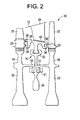
- FIG. 2 another embodiment of the turbine section 10 is shown, in which the inner support ring 26 is omitted and the sealing member 28 forms the flow path along with the buckets 22.
- the nozzle vanes 24 are individually attached to the turbine shell in a cantilever arrangement.
- a controllable gap 42 is defined between the sealing member 28 and the nozzle 24.
- an exemplary method for reducing secondary airflow in a gas turbine includes disposing the rotor disks 20 in at least one of the compression section and the turbine section.
- the turbine nozzle vanes 24 are disposed axially between the rotor disks 20.
- the sealing member 28 is attached at a fixed position relative to the rotor disks 20, and disposed to contact the buckets 22.
- the combustion section is activated to cause rotation of the rotors 20 and direct an air flow through a conduit formed by the buckets 22 and at least one of the nozzle stages 12 and the sealing member 28.
- the sealing member 28 prevents or reduces leakage of the air flow from the conduit during operation of the turbine 10.
- any other suitable type of turbine may be used.
- the systems and methods described herein may be used with a steam turbine or turbine including both gas and steam generation.
- the devices, systems and methods described herein provide numerous advantages over prior art systems.
- the devices, systems and methods provide the technical effect of increasing efficiency and performance of the turbine by reducing the number of components and by reducing or eliminating the need for cooling gas flows.
- the need for disk rim cover plates to seal the connection between the rotor disks and the buckets may be eliminated.
- the prevention of air flow leakage into interior cavities of the turbine reduces the level of cooling flow required, thus improving turbine efficiency and reducing cost.
Abstract
Description
- The subject matter disclosed herein relates to gas turbines and, more particularly, to inter-stage seals in gas turbines.
- Turbine components are typically directly exposed to high temperature gases, and therefore require cooling to meet their useful life. For example, some of the compressor discharge air is diverted from the combustion process for cooling rotor components of the turbine.
- Turbine buckets, blades and vanes typically include internal cooling channels therein which receive compressor discharge air or other cooling gases for cooling thereof during operation. In addition, turbine rotor disks which support the buckets are subject to significant thermal loads and thus also need to be cooled to increase their lifetimes.
- The main flow path of the turbine is designed to confine combustion gases as they flow through the turbine. Turbine rotor structural components must be provided with cooling air independent of the main gas flow to prevent ingestion of the hot combustion gases therein during operation, and must be shielded from direct exposure to the hot flowpath gas.
- Such confinement is accomplished by rotary seals positioned between the rotating turbine buckets to prevent ingestion or back flow of the hot air or gases into interior portions of the turbine rotor structure. Such rotary seals are insufficient to completely protect the interior components, such as the rotor structure, rotor and rotor disks, requiring the additional use of purge flows of cooling air into and through the rotor cavity. Such additional measures to protect the interior components increase the cost and complexity and hinder the performance of gas turbines.
- Accordingly, there is a need for improved systems and methods for cooling turbine engines, that reduce rotor cooling air purge flow levels, reduce complexity and preserve or improve turbine performance.
- A device for reducing secondary airflow in a gas turbine, constructed in accordance with exemplary embodiments of the invention includes: an inter-stage sealing member located between a plurality of first turbine buckets attached to a first rotor disk and a plurality of second turbine buckets attached to a second rotor disk, the first rotor disk and the second rotor disk being rotatable about a central axis. The inter-stage sealing member is configured to be attached in a fixed position relative to the first rotor disk and the second rotor disk, and to contact the plurality of first buckets and the plurality of second buckets in a sealing engagement.
- Other exemplary embodiments of the invention include a gas turbine system including: a plurality of first turbine buckets attached to a first rotatable rotor disk; a plurality of second turbine buckets attached to a second rotatable rotor disk; a plurality of stationary radially extending turbine nozzles located axially between the first rotor disk and the second rotor disk; and a rotatable inter-stage sealing member attached to the first and second rotating disks, the rotatable sealing member configured to contact the plurality of first turbine buckets and the plurality of second turbine buckets to form a sealed flow path defined by the plurality of first and second buckets and at least one of the plurality of stationary nozzles and the sealing member.
- Additional features and advantages are realized through the techniques of exemplary embodiments of the invention. Other embodiments and aspects of the invention are described in detail herein and are considered a part of the claimed invention. For a better understanding of the invention with advantages and features thereof, refer to the description and to the drawings.
- There follows a detailed description of embodiments of the invention by way of example only with reference to the accompanying drawings, in which:
-
FIG. 1 is a side view of a portion of a gas turbine including a sealing assembly in accordance with an exemplary embodiment of the invention; and -
FIG. 2 is a side view of another exemplary embodiment of the sealing assembly ofFIG. 1 . - Referring to
FIG. 1 , a portion of a turbine section of a gas turbine constructed in accordance with an exemplary embodiment of the invention is indicated generally at 10. Theturbine 10 includes alternatinginter-stage nozzle stages 12 andturbine stages inter-stage sealing assembly 18 is disposed between theturbine stages FIG. 1 shows a side cross-sectional view of afirst turbine stage 14, asecond turbine stage 16, and thenozzle stage 12 andsealing assembly 18 therebetween. Although the embodiments described herein are described with reference to the turbine section of a gas turbine, the embodiments may also be utilized in conjunction with various compression sections of a gas turbine. - Each
turbine stage rotor disk 20 that is attached to a rotor shaft (not shown) that causes therotor disks 20 to rotate about a central axis. A plurality of blades orbuckets 22 are removably attached to an outer periphery of eachrotor disk 20. Thebuckets 22 are attached by any suitable mechanism, such as an axially extending dovetail connection. In one embodiment, thebuckets 22 each include abucket platform 23 configured to attach to thecorresponding rotor disk 20. As used herein, an "axial" direction is a direction parallel to the central axis, and a "radial" direction is a direction extending from the central axis and perpendicular to the central axis. An "outer" location refers to a location in the radial direction that is farther away from the central axis than an "inner" location. - The
nozzle stage 12 includes a plurality ofnozzle vanes 24 that are connected to an outer casing assembly such as a turbine shell or an outer support ring attached thereto, and extend radially toward the central axis. In one embodiment, each of thenozzle vanes 24 are attached to an inner support ring, or segments forming aring 26 having a diameter less than a diameter of the outer support ring, or segments forming a ring. - The
inter-stage sealing assembly 18 is included to reduce or prevent heated gas or air from leaking into interior portions of theturbine 10 and away from the flow path defined by thebuckets 22 and thenozzle stage 12. The sealing assembly includes asealing member 28 that is attached in a fixed position relative to the rotatingrotor disks 20, and therefore rotates along with therotor disks 20. The sealingmember 28 is also disposed against a surface of thebuckets 22, such as against thebucket platforms 23, to cause a sealing connection between the sealingmember 28 and thebuckets 22. The corresponding gas flow path is accordingly defined by thebuckets 22 and theinner support ring 26, with leakage of gas flow from the flow path being prevented by the sealingmember 28. - The sealing
member 28 is cast or otherwise made from high temperature materials capable of withstanding elevated temperatures such as 1500 °F. Examples of such materials include nickel based superalloys such as those alloys used for flowpath components. - In one embodiment, the sealing
member 28 is attached to aninter-stage disk 30 that is attached in fixed position relative to therotor disks 20. In one embodiment, theinter-stage disk 30 is attached to the rotor disks by abolt connection 31 or other suitable attachment to, for example,flanges 33. The attachment designs described herein are not limited. Any suitable attached mechanism may be used to attach the sealingmember 28 in a fixed position relative to therotor disks 20. - In one embodiment, the sealing
member 28 is a continuous circumferential ring having an outer diameter less than an inner diameter of the nozzleinner support ring 26 and/or thenozzle vane 24. In another embodiment, the sealingmember 28 is segmented and is attached to theinter-stage disk 30 by a removable connection such as acircumferentail dovetail connection 32. In one embodiment, the sealingmember 28 includes at least oneextension 34 at each axial end of the sealingmember 28 that contact at least one axially-extendingprotrusion 36 on each of thebuckets 22 such as thebucket platforms 23. This contact between theextensions 34 and theprotrusions 36 provides the seal between thebuckets 22 and the sealingmember 28. This contact can be metal-to-metal or contain a separate sealing feature between theextension 34 and theprotrusion 36. - In one embodiment, the sealing
member 28 is made from high temperature-resistant materials that can withstand the high temperature of the flow path. The sealingmember 28 can be segmented with sealing features between circumferential segments, such as spline seals. The sealingmember 28 is made from any of various materials such as metal castings, forgings, composite materials and ceramic materials. In another embodiment, cooling air or other cooling means are applied to the sealingmember 28 to counteract the high temperatures in the flow path. The sealingmember 28 thus protects the lower temperature rotating structures such as the rotor androtor disks 20 from the hot gas of the flowpath, allowing for greatly reduced or eliminated rotor cavity purge flow levels since any local flow path ingestion occurs only on high temperature capable materials. In one embodiment, abuffer cavity 40 is formed between the sealingmember 28 and theinner support ring 26. Thiscavity 40 is surrounded by the high temperature materials of the sealingmember 28,ring 26 andbucket platforms 23. - Referring to
FIG. 2 , another embodiment of theturbine section 10 is shown, in which theinner support ring 26 is omitted and the sealingmember 28 forms the flow path along with thebuckets 22. In this embodiment, thenozzle vanes 24 are individually attached to the turbine shell in a cantilever arrangement. In one embodiment, acontrollable gap 42 is defined between the sealingmember 28 and thenozzle 24. - In one embodiment, an exemplary method for reducing secondary airflow in a gas turbine is provided. The method includes disposing the
rotor disks 20 in at least one of the compression section and the turbine section. Theturbine nozzle vanes 24 are disposed axially between therotor disks 20. The sealingmember 28 is attached at a fixed position relative to therotor disks 20, and disposed to contact thebuckets 22. The combustion section is activated to cause rotation of therotors 20 and direct an air flow through a conduit formed by thebuckets 22 and at least one of the nozzle stages 12 and the sealingmember 28. The sealingmember 28 prevents or reduces leakage of the air flow from the conduit during operation of theturbine 10. - Although the systems and methods described herein are provided in conjunction with gas turbines, any other suitable type of turbine may be used. For example, the systems and methods described herein may be used with a steam turbine or turbine including both gas and steam generation.
- The devices, systems and methods described herein provide numerous advantages over prior art systems. For example, the devices, systems and methods provide the technical effect of increasing efficiency and performance of the turbine by reducing the number of components and by reducing or eliminating the need for cooling gas flows. For example, the need for disk rim cover plates to seal the connection between the rotor disks and the buckets may be eliminated. Furthermore, the prevention of air flow leakage into interior cavities of the turbine reduces the level of cooling flow required, thus improving turbine efficiency and reducing cost.
- In general, this written description uses examples to disclose the invention, including the best mode, and also to enable any person skilled in the art to practice the invention, including making and using any devices or systems and performing any incorporated methods. The patentable scope of the invention is defined by the claims, and may include other examples that occur to those skilled in the art. Such other examples are intended to be within the scope of exemplary embodiments of the invention if they have structural elements that do not differ from the literal language of the claims, or if they include equivalent structural elements with insubstantial differences from the literal language of the claims.
Claims (14)
- A device for reducing secondary airflow in a gas turbine (10), the device comprising:an inter-stage sealing member (28) located between a plurality of first turbine buckets (22) attached to a first rotor disk (20) and a plurality of second turbine buckets (22) attached to a second rotor disk (20), the first rotor disk (20) and the second rotor disk (20) being rotatable about a central axis,the inter-stage sealing member (28) configured to be attached in a fixed position relative to the first rotor disk (20) and the second rotor disk (20), and to contact the plurality of first buckets (22) and the plurality of second buckets (22) in a sealing engagement.
- The device of claim 1, wherein the sealing member (28) is a circumferential ring member (28) rotatable about the central axis.
- The device of claim 1, wherein the sealing member (28) is a segmented structure including a plurality of segments and a sealing feature disposed between each of the plurality of segments.
- The device of any of the preceding claims, wherein the sealing member is made from a high temperature material capable of withstanding flowpath gas temperatures.
- The device of any of the preceding claims, wherein the sealing member is an actively cooled structure.
- The device of claim 1, further comprising an additional inter-stage rotor disk (30) in a fixed position relative to the first rotor disk and the second rotor disk, the additional inter-stage rotor disk (30) connected to the sealing member (28) and supporting the sealing member (28) in contact with the plurality of first buckets (22) and second buckets (22).
- The device of claim 6, wherein the additional rotor disk (30) is connectable to the sealing member (28) by a circumferential dovetail connection (32).
- The device of any of the preceding claims, wherein the sealing member (28) includes at least one extension member (34) extending axially from each end of the sealing member (28).
- The device of claim 4, wherein the at least one extension member (28) is engageable with at least one axially extending protrusion (36) on each of the plurality of first buckets (22) and the plurality of second buckets (22) to form the sealing engagement.
- The device of any of the preceding claims, further comprising an inter-stage nozzle assembly (12) including a plurality of stationary radially extending turbine nozzles (24) located axially between the first rotor disk (20) and the second rotor disk (20) and connected to an inner support ring (26), the nozzle assembly (18) and the plurality of first and second buckets (22) forming an air flow path.
- A gas turbine (10) system comprising:a plurality of first turbine buckets (22) attached to a first rotatable rotor disk (20) ;a plurality of second turbine buckets (22) attached to a second rotatable rotor disk (20) ;a plurality of stationary radially extending turbine nozzles (24) located axially between the first rotor disk (20) and the second rotor disk (20) ; anda rotatable inter-stage sealing member (28) attached to the first and second rotating disks, the rotatable sealing member (28) configured to contact the plurality of first turbine buckets (22) and the plurality of second turbine buckets (22) to form a sealed flow path defined by the plurality of first and second buckets (22) and at least one of the plurality of stationary nozzles and the sealing member (28).
- The system of claim 11, further comprising an additional inter-stage rotor disk (30) in a fixed position relative to the first rotor disk (20) and the second rotor disk (20), the additional inter-stage rotor disk (30) connected to the sealing member (28) and supporting the sealing member (28) in contact with the plurality of first buckets (22) and second buckets (22).
- The system of claim 11 or 12, wherein the plurality of stationary nozzles are connected to an inner support ring, and the inner support ring and the plurality of first and second buckets forming an air flow path.
- The system of any of claims 11 to 13, wherein the sealing member and the plurality of first and second buckets form a sealed air flow path.
Applications Claiming Priority (1)
| Application Number | Priority Date | Filing Date | Title |
|---|---|---|---|
| US12/353,305 US8221062B2 (en) | 2009-01-14 | 2009-01-14 | Device and system for reducing secondary air flow in a gas turbine |
Publications (3)
| Publication Number | Publication Date |
|---|---|
| EP2208860A2 true EP2208860A2 (en) | 2010-07-21 |
| EP2208860A3 EP2208860A3 (en) | 2012-12-05 |
| EP2208860B1 EP2208860B1 (en) | 2020-06-24 |
Family
ID=41720549
Family Applications (1)
| Application Number | Title | Priority Date | Filing Date |
|---|---|---|---|
| EP10150525.3A Active EP2208860B1 (en) | 2009-01-14 | 2010-01-12 | Interstage seal for a gas turbine and corresponding gas turbine |
Country Status (5)
| Country | Link |
|---|---|
| US (1) | US8221062B2 (en) |
| EP (1) | EP2208860B1 (en) |
| JP (1) | JP5491874B2 (en) |
| CN (1) | CN101845996B (en) |
| HU (1) | HUE051990T2 (en) |
Cited By (10)
| Publication number | Priority date | Publication date | Assignee | Title |
|---|---|---|---|---|
| FR3009336A1 (en) * | 2013-08-05 | 2015-02-06 | Snecma | ROTARY TURBOMACHINE ASSEMBLY WITH A VIROLE LABYRINTHE CMC |
| WO2015130497A1 (en) * | 2014-02-25 | 2015-09-03 | Siemens Energy, Inc. | Thermal shields for gas turbine rotor |
| EP3020919A1 (en) * | 2014-11-17 | 2016-05-18 | United Technologies Corporation | Fiber reinforced spacer for a gas turbine engine |
| CN106460539A (en) * | 2014-05-27 | 2017-02-22 | 赛峰飞机发动机公司 | Sealing plate with fuse function |
| EP3244022A1 (en) * | 2016-05-10 | 2017-11-15 | General Electric Company | Turbine assembly, turbine inner wall assembly and turbine assembly method |
| EP3287605A1 (en) * | 2016-08-23 | 2018-02-28 | United Technologies Corporation | Rim seal for gas turbine engine |
| EP3318724A1 (en) * | 2016-11-04 | 2018-05-09 | Siemens Aktiengesellschaft | Sealing segment of a rotor and rotor |
| EP3523507B1 (en) | 2016-10-07 | 2020-06-24 | Safran Aircraft Engines | Movable ring assembly for a turbine engine turbine |
| IT202000004585A1 (en) * | 2020-03-04 | 2021-09-04 | Nuovo Pignone Tecnologie Srl | Improved turbine and blade for root protection from the hot gases of the flow path. |
| RU2809677C1 (en) * | 2020-03-04 | 2023-12-14 | НУОВО ПИНЬОНЕ ТЕКНОЛОДЖИ - С.р.л. | Improved turbine and blade to protect blade root from hot gases from flow channel |
Families Citing this family (31)
| Publication number | Priority date | Publication date | Assignee | Title |
|---|---|---|---|---|
| US8376697B2 (en) * | 2008-09-25 | 2013-02-19 | Siemens Energy, Inc. | Gas turbine sealing apparatus |
| US8845284B2 (en) | 2010-07-02 | 2014-09-30 | General Electric Company | Apparatus and system for sealing a turbine rotor |
| US9217334B2 (en) | 2011-10-26 | 2015-12-22 | General Electric Company | Turbine cover plate assembly |
| US9051845B2 (en) | 2012-01-05 | 2015-06-09 | General Electric Company | System for axial retention of rotating segments of a turbine |
| US9080456B2 (en) * | 2012-01-20 | 2015-07-14 | General Electric Company | Near flow path seal with axially flexible arms |
| US8864453B2 (en) | 2012-01-20 | 2014-10-21 | General Electric Company | Near flow path seal for a turbomachine |
| US20130186103A1 (en) * | 2012-01-20 | 2013-07-25 | General Electric Company | Near flow path seal for a turbomachine |
| US11459157B2 (en) | 2012-02-13 | 2022-10-04 | Polytex Fibers Llc | Woven plastic bags with features that reduce leakage, breakage and infestations |
| US9540940B2 (en) | 2012-03-12 | 2017-01-10 | General Electric Company | Turbine interstage seal system |
| US9151169B2 (en) * | 2012-03-29 | 2015-10-06 | General Electric Company | Near-flow-path seal isolation dovetail |
| US20130264779A1 (en) * | 2012-04-10 | 2013-10-10 | General Electric Company | Segmented interstage seal system |
| US9169849B2 (en) | 2012-05-08 | 2015-10-27 | United Technologies Corporation | Gas turbine engine compressor stator seal |
| US9169737B2 (en) * | 2012-11-07 | 2015-10-27 | United Technologies Corporation | Gas turbine engine rotor seal |
| EP2935837B1 (en) | 2012-12-19 | 2019-02-06 | United Technologies Corporation | Segmented seal for a gas turbine engine |
| US10808616B2 (en) | 2013-02-28 | 2020-10-20 | Raytheon Technologies Corporation | Method and apparatus for handling pre-diffuser airflow for cooling high pressure turbine components |
| US9605596B2 (en) | 2013-03-08 | 2017-03-28 | United Technologies Corporation | Duct blocker seal assembly for a gas turbine engine |
| US9441639B2 (en) * | 2013-05-13 | 2016-09-13 | General Electric Company | Compressor rotor heat shield |
| CN103541776B (en) * | 2013-10-15 | 2015-12-30 | 北京华清燃气轮机与煤气化联合循环工程技术有限公司 | Axial seal structure between a kind of gas turbine wheel disk |
| US10465519B2 (en) * | 2013-10-17 | 2019-11-05 | Pratt & Whitney Canada Corp. | Fastening system for rotor hubs |
| US9404376B2 (en) * | 2013-10-28 | 2016-08-02 | General Electric Company | Sealing component for reducing secondary airflow in a turbine system |
| US10287905B2 (en) | 2013-11-11 | 2019-05-14 | United Technologies Corporation | Segmented seal for gas turbine engine |
| US11305927B2 (en) | 2014-04-04 | 2022-04-19 | Polytex Fibers Llc | Easy open plastic bags |
| CA2944904C (en) | 2014-04-04 | 2022-08-16 | Polytex Fibers Corporation | Woven plastic bags with features that reduce leakage, breakage and infestations |
| US11472622B2 (en) | 2014-04-04 | 2022-10-18 | Polytex Fibers Llc | Woven plastic bags with features that reduce leakage, breakage, and infestations |
| US10662793B2 (en) * | 2014-12-01 | 2020-05-26 | General Electric Company | Turbine wheel cover-plate mounted gas turbine interstage seal |
| US20160186592A1 (en) * | 2014-12-31 | 2016-06-30 | General Electric Company | Flowpath boundary and rotor assemblies in gas turbines |
| US10337345B2 (en) | 2015-02-20 | 2019-07-02 | General Electric Company | Bucket mounted multi-stage turbine interstage seal and method of assembly |
| KR102153015B1 (en) * | 2017-11-21 | 2020-09-07 | 두산중공업 주식회사 | Rotor disk assembly and gas turbine including the same |
| CN112534119B (en) * | 2018-08-02 | 2023-04-14 | 西门子能源全球有限两合公司 | Rotor with a rotor component arranged between two rotor disks |
| GB2581964A (en) * | 2019-03-04 | 2020-09-09 | Rolls Royce Plc | A turbomachine for a gas turbine engine |
| KR102127429B1 (en) | 2019-06-05 | 2020-06-26 | 두산중공업 주식회사 | Sealing structure between turbine rotor disk and interstage disk |
Family Cites Families (19)
| Publication number | Priority date | Publication date | Assignee | Title |
|---|---|---|---|---|
| GB706730A (en) * | 1951-04-11 | 1954-04-07 | Vickers Electrical Co Ltd | Improvements relating to turbine rotors |
| US3551068A (en) * | 1968-10-25 | 1970-12-29 | Westinghouse Electric Corp | Rotor structure for an axial flow machine |
| DE2555911A1 (en) * | 1975-12-12 | 1977-06-23 | Motoren Turbinen Union | ROTOR FOR FLOW MACHINES, IN PARTICULAR GAS TURBINE JETS |
| US5080556A (en) * | 1990-09-28 | 1992-01-14 | General Electric Company | Thermal seal for a gas turbine spacer disc |
| US5236302A (en) * | 1991-10-30 | 1993-08-17 | General Electric Company | Turbine disk interstage seal system |
| GB2307520B (en) * | 1995-11-14 | 1999-07-07 | Rolls Royce Plc | A gas turbine engine |
| DE19940525A1 (en) * | 1999-08-26 | 2001-03-01 | Asea Brown Boveri | Heat accumulation unit for a rotor arrangement |
| US6464453B2 (en) * | 2000-12-04 | 2002-10-15 | General Electric Company | Turbine interstage sealing ring |
| US6769865B2 (en) * | 2002-03-22 | 2004-08-03 | General Electric Company | Band cooled turbine nozzle |
| EP1371814A1 (en) * | 2002-06-11 | 2003-12-17 | ALSTOM (Switzerland) Ltd | Sealing arrangement for a rotor of a turbomachine |
| US7488153B2 (en) * | 2002-07-01 | 2009-02-10 | Alstom Technology Ltd. | Steam turbine |
| US7252481B2 (en) * | 2004-05-14 | 2007-08-07 | Pratt & Whitney Canada Corp. | Natural frequency tuning of gas turbine engine blades |
| US7410345B2 (en) * | 2005-04-11 | 2008-08-12 | General Electric Company | Turbine nozzle retention key |
| US7520718B2 (en) * | 2005-07-18 | 2009-04-21 | Siemens Energy, Inc. | Seal and locking plate for turbine rotor assembly between turbine blade and turbine vane |
| WO2007023158A1 (en) * | 2005-08-23 | 2007-03-01 | Alstom Technology Ltd | Device for securing installation of and fixing a heat shield element for a rotor unit of a flow engine |
| US8573940B2 (en) * | 2006-07-07 | 2013-11-05 | United Technologies Corporation | Interlocking knife edge seals |
| EP1898054B1 (en) * | 2006-08-25 | 2018-05-30 | Ansaldo Energia IP UK Limited | Gas turbine |
| US7870742B2 (en) * | 2006-11-10 | 2011-01-18 | General Electric Company | Interstage cooled turbine engine |
| ATE472046T1 (en) * | 2007-09-24 | 2010-07-15 | Alstom Technology Ltd | SEAL IN GAS TURBINE |
-
2009
- 2009-01-14 US US12/353,305 patent/US8221062B2/en active Active
-
2010
- 2010-01-12 HU HUE10150525A patent/HUE051990T2/en unknown
- 2010-01-12 JP JP2010003534A patent/JP5491874B2/en active Active
- 2010-01-12 EP EP10150525.3A patent/EP2208860B1/en active Active
- 2010-01-14 CN CN201010005139.7A patent/CN101845996B/en active Active
Non-Patent Citations (1)
| Title |
|---|
| None |
Cited By (20)
| Publication number | Priority date | Publication date | Assignee | Title |
|---|---|---|---|---|
| FR3009336A1 (en) * | 2013-08-05 | 2015-02-06 | Snecma | ROTARY TURBOMACHINE ASSEMBLY WITH A VIROLE LABYRINTHE CMC |
| WO2015130497A1 (en) * | 2014-02-25 | 2015-09-03 | Siemens Energy, Inc. | Thermal shields for gas turbine rotor |
| CN106062314A (en) * | 2014-02-25 | 2016-10-26 | 西门子能源公司 | Thermal shields for gas turbine rotor |
| US9771802B2 (en) | 2014-02-25 | 2017-09-26 | Siemens Energy, Inc. | Thermal shields for gas turbine rotor |
| CN106460539A (en) * | 2014-05-27 | 2017-02-22 | 赛峰飞机发动机公司 | Sealing plate with fuse function |
| CN106460539B (en) * | 2014-05-27 | 2018-02-02 | 赛峰飞机发动机公司 | sealing plate with insurance function |
| US10648481B2 (en) | 2014-11-17 | 2020-05-12 | United Technologies Corporation | Fiber reinforced spacer for a gas turbine engine |
| EP3020919A1 (en) * | 2014-11-17 | 2016-05-18 | United Technologies Corporation | Fiber reinforced spacer for a gas turbine engine |
| EP3244022A1 (en) * | 2016-05-10 | 2017-11-15 | General Electric Company | Turbine assembly, turbine inner wall assembly and turbine assembly method |
| EP3287605A1 (en) * | 2016-08-23 | 2018-02-28 | United Technologies Corporation | Rim seal for gas turbine engine |
| US10533445B2 (en) | 2016-08-23 | 2020-01-14 | United Technologies Corporation | Rim seal for gas turbine engine |
| EP3523507B1 (en) | 2016-10-07 | 2020-06-24 | Safran Aircraft Engines | Movable ring assembly for a turbine engine turbine |
| WO2018082907A1 (en) * | 2016-11-04 | 2018-05-11 | Siemens Aktiengesellschaft | Sealing segment of a rotor and rotor |
| EP3318724A1 (en) * | 2016-11-04 | 2018-05-09 | Siemens Aktiengesellschaft | Sealing segment of a rotor and rotor |
| IT202000004585A1 (en) * | 2020-03-04 | 2021-09-04 | Nuovo Pignone Tecnologie Srl | Improved turbine and blade for root protection from the hot gases of the flow path. |
| WO2021175488A1 (en) * | 2020-03-04 | 2021-09-10 | Nuovo Pignone Tecnologie - S.R.L. | Improved turbine and blade for the protection of the root from flow path hot gases |
| WO2021175495A1 (en) * | 2020-03-04 | 2021-09-10 | Nuovo Pignone Tecnologie - S.R.L. | Improved turbine and blade for the protection of the root from flow path hot gases |
| GB2608336A (en) * | 2020-03-04 | 2022-12-28 | Nuovo Pignone Tecnologie Srl | Improved turbine and blade for the protection of the root from flow path hot gases |
| GB2614118A (en) * | 2020-03-04 | 2023-06-28 | Nuovo Pignone Tecnologie Srl | Improved turbine and blade for the protection of the root from flow path hot gases |
| RU2809677C1 (en) * | 2020-03-04 | 2023-12-14 | НУОВО ПИНЬОНЕ ТЕКНОЛОДЖИ - С.р.л. | Improved turbine and blade to protect blade root from hot gases from flow channel |
Also Published As
| Publication number | Publication date |
|---|---|
| EP2208860B1 (en) | 2020-06-24 |
| CN101845996B (en) | 2015-04-01 |
| JP5491874B2 (en) | 2014-05-14 |
| US8221062B2 (en) | 2012-07-17 |
| CN101845996A (en) | 2010-09-29 |
| EP2208860A3 (en) | 2012-12-05 |
| JP2010164054A (en) | 2010-07-29 |
| US20100178160A1 (en) | 2010-07-15 |
| HUE051990T2 (en) | 2021-04-28 |
Similar Documents
| Publication | Publication Date | Title |
|---|---|---|
| US8221062B2 (en) | Device and system for reducing secondary air flow in a gas turbine | |
| US8419356B2 (en) | Turbine seal assembly | |
| CA2662039C (en) | Turbine shroud gas path duct interface | |
| US7824152B2 (en) | Multivane segment mounting arrangement for a gas turbine | |
| CN101839152B (en) | Ceramic matrix composite turbine engine and nozzle assembly thereof | |
| US9115596B2 (en) | Blade outer air seal having anti-rotation feature | |
| EP2564032B1 (en) | Component of a turbine with leaf seals and method for sealing against leakage between a vane and a carrier element | |
| US8388310B1 (en) | Turbine disc sealing assembly | |
| EP3095958B1 (en) | System for thermally shielding a portion of a gas turbine shroud assembly | |
| US8511976B2 (en) | Turbine seal system | |
| EP2568121B1 (en) | Stepped conical honeycomb seal carrier and corresponding annular seal | |
| US7588412B2 (en) | Cooled shroud assembly and method of cooling a shroud | |
| US9200527B2 (en) | Systems, methods, and apparatus for a turbine interstage rim seal | |
| EP2867502B1 (en) | Gas turbine engine component having platform cooling channel | |
| JP2012013080A (en) | Rotor assembly for use in gas turbine engines and method for assembling the same | |
| EP2984296A1 (en) | Blade outer air seal with secondary air sealing | |
| JP6405185B2 (en) | Seal parts that reduce the secondary air flow in the turbine system | |
| CN110735667B (en) | Sealing assembly for a turbine rotor of a turbomachine and corresponding turbine | |
| EP3047130B1 (en) | A gas turbine seal assembly comprising splined honeycomb seals | |
| US11261747B2 (en) | Ceramic matrix composite vane with added platform | |
| EP3047111A2 (en) | Insert and standoff design for a gas turbine engine vane | |
| US20210207487A1 (en) | Turbomachine blading angular sector with seal between sectors | |
| RU2809677C1 (en) | Improved turbine and blade to protect blade root from hot gases from flow channel |
Legal Events
| Date | Code | Title | Description |
|---|---|---|---|
| PUAI | Public reference made under article 153(3) epc to a published international application that has entered the european phase |
Free format text: ORIGINAL CODE: 0009012 |
|
| AK | Designated contracting states |
Kind code of ref document: A2 Designated state(s): AT BE BG CH CY CZ DE DK EE ES FI FR GB GR HR HU IE IS IT LI LT LU LV MC MK MT NL NO PL PT RO SE SI SK SM TR |
|
| AX | Request for extension of the european patent |
Extension state: AL BA RS |
|
| PUAL | Search report despatched |
Free format text: ORIGINAL CODE: 0009013 |
|
| AK | Designated contracting states |
Kind code of ref document: A3 Designated state(s): AT BE BG CH CY CZ DE DK EE ES FI FR GB GR HR HU IE IS IT LI LT LU LV MC MK MT NL NO PL PT RO SE SI SK SM TR |
|
| AX | Request for extension of the european patent |
Extension state: AL BA RS |
|
| RIC1 | Information provided on ipc code assigned before grant |
Ipc: F01D 11/00 20060101AFI20121026BHEP |
|
| 17P | Request for examination filed |
Effective date: 20130605 |
|
| RBV | Designated contracting states (corrected) |
Designated state(s): AT BE BG CH CY CZ DE DK EE ES FI FR GB GR HR HU IE IS IT LI LT LU LV MC MK MT NL NO PL PT RO SE SI SK SM TR |
|
| REG | Reference to a national code |
Ref country code: DE Ref legal event code: R079 Ref document number: 602010064706 Country of ref document: DE Free format text: PREVIOUS MAIN CLASS: F01D0011000000 Ipc: F01D0005060000 |
|
| RIC1 | Information provided on ipc code assigned before grant |
Ipc: F01D 11/00 20060101ALI20191122BHEP Ipc: F01D 5/06 20060101AFI20191122BHEP |
|
| GRAP | Despatch of communication of intention to grant a patent |
Free format text: ORIGINAL CODE: EPIDOSNIGR1 |
|
| STAA | Information on the status of an ep patent application or granted ep patent |
Free format text: STATUS: GRANT OF PATENT IS INTENDED |
|
| INTG | Intention to grant announced |
Effective date: 20200115 |
|
| GRAS | Grant fee paid |
Free format text: ORIGINAL CODE: EPIDOSNIGR3 |
|
| GRAA | (expected) grant |
Free format text: ORIGINAL CODE: 0009210 |
|
| STAA | Information on the status of an ep patent application or granted ep patent |
Free format text: STATUS: THE PATENT HAS BEEN GRANTED |
|
| AK | Designated contracting states |
Kind code of ref document: B1 Designated state(s): AT BE BG CH CY CZ DE DK EE ES FI FR GB GR HR HU IE IS IT LI LT LU LV MC MK MT NL NO PL PT RO SE SI SK SM TR |
|
| REG | Reference to a national code |
Ref country code: GB Ref legal event code: FG4D |
|
| REG | Reference to a national code |
Ref country code: CH Ref legal event code: EP |
|
| REG | Reference to a national code |
Ref country code: DE Ref legal event code: R096 Ref document number: 602010064706 Country of ref document: DE |
|
| REG | Reference to a national code |
Ref country code: AT Ref legal event code: REF Ref document number: 1284086 Country of ref document: AT Kind code of ref document: T Effective date: 20200715 |
|
| REG | Reference to a national code |
Ref country code: IE Ref legal event code: FG4D |
|
| REG | Reference to a national code |
Ref country code: NL Ref legal event code: FP |
|
| PG25 | Lapsed in a contracting state [announced via postgrant information from national office to epo] |
Ref country code: GR Free format text: LAPSE BECAUSE OF FAILURE TO SUBMIT A TRANSLATION OF THE DESCRIPTION OR TO PAY THE FEE WITHIN THE PRESCRIBED TIME-LIMIT Effective date: 20200925 Ref country code: SE Free format text: LAPSE BECAUSE OF FAILURE TO SUBMIT A TRANSLATION OF THE DESCRIPTION OR TO PAY THE FEE WITHIN THE PRESCRIBED TIME-LIMIT Effective date: 20200624 Ref country code: NO Free format text: LAPSE BECAUSE OF FAILURE TO SUBMIT A TRANSLATION OF THE DESCRIPTION OR TO PAY THE FEE WITHIN THE PRESCRIBED TIME-LIMIT Effective date: 20200924 Ref country code: FI Free format text: LAPSE BECAUSE OF FAILURE TO SUBMIT A TRANSLATION OF THE DESCRIPTION OR TO PAY THE FEE WITHIN THE PRESCRIBED TIME-LIMIT Effective date: 20200624 Ref country code: LT Free format text: LAPSE BECAUSE OF FAILURE TO SUBMIT A TRANSLATION OF THE DESCRIPTION OR TO PAY THE FEE WITHIN THE PRESCRIBED TIME-LIMIT Effective date: 20200624 |
|
| REG | Reference to a national code |
Ref country code: LT Ref legal event code: MG4D |
|
| PG25 | Lapsed in a contracting state [announced via postgrant information from national office to epo] |
Ref country code: HR Free format text: LAPSE BECAUSE OF FAILURE TO SUBMIT A TRANSLATION OF THE DESCRIPTION OR TO PAY THE FEE WITHIN THE PRESCRIBED TIME-LIMIT Effective date: 20200624 Ref country code: BG Free format text: LAPSE BECAUSE OF FAILURE TO SUBMIT A TRANSLATION OF THE DESCRIPTION OR TO PAY THE FEE WITHIN THE PRESCRIBED TIME-LIMIT Effective date: 20200924 Ref country code: LV Free format text: LAPSE BECAUSE OF FAILURE TO SUBMIT A TRANSLATION OF THE DESCRIPTION OR TO PAY THE FEE WITHIN THE PRESCRIBED TIME-LIMIT Effective date: 20200624 |
|
| REG | Reference to a national code |
Ref country code: AT Ref legal event code: MK05 Ref document number: 1284086 Country of ref document: AT Kind code of ref document: T Effective date: 20200624 |
|
| PG25 | Lapsed in a contracting state [announced via postgrant information from national office to epo] |
Ref country code: PT Free format text: LAPSE BECAUSE OF FAILURE TO SUBMIT A TRANSLATION OF THE DESCRIPTION OR TO PAY THE FEE WITHIN THE PRESCRIBED TIME-LIMIT Effective date: 20201026 Ref country code: SM Free format text: LAPSE BECAUSE OF FAILURE TO SUBMIT A TRANSLATION OF THE DESCRIPTION OR TO PAY THE FEE WITHIN THE PRESCRIBED TIME-LIMIT Effective date: 20200624 Ref country code: AT Free format text: LAPSE BECAUSE OF FAILURE TO SUBMIT A TRANSLATION OF THE DESCRIPTION OR TO PAY THE FEE WITHIN THE PRESCRIBED TIME-LIMIT Effective date: 20200624 Ref country code: EE Free format text: LAPSE BECAUSE OF FAILURE TO SUBMIT A TRANSLATION OF THE DESCRIPTION OR TO PAY THE FEE WITHIN THE PRESCRIBED TIME-LIMIT Effective date: 20200624 Ref country code: RO Free format text: LAPSE BECAUSE OF FAILURE TO SUBMIT A TRANSLATION OF THE DESCRIPTION OR TO PAY THE FEE WITHIN THE PRESCRIBED TIME-LIMIT Effective date: 20200624 Ref country code: ES Free format text: LAPSE BECAUSE OF FAILURE TO SUBMIT A TRANSLATION OF THE DESCRIPTION OR TO PAY THE FEE WITHIN THE PRESCRIBED TIME-LIMIT Effective date: 20200624 Ref country code: IT Free format text: LAPSE BECAUSE OF FAILURE TO SUBMIT A TRANSLATION OF THE DESCRIPTION OR TO PAY THE FEE WITHIN THE PRESCRIBED TIME-LIMIT Effective date: 20200624 Ref country code: CZ Free format text: LAPSE BECAUSE OF FAILURE TO SUBMIT A TRANSLATION OF THE DESCRIPTION OR TO PAY THE FEE WITHIN THE PRESCRIBED TIME-LIMIT Effective date: 20200624 |
|
| PG25 | Lapsed in a contracting state [announced via postgrant information from national office to epo] |
Ref country code: IS Free format text: LAPSE BECAUSE OF FAILURE TO SUBMIT A TRANSLATION OF THE DESCRIPTION OR TO PAY THE FEE WITHIN THE PRESCRIBED TIME-LIMIT Effective date: 20201024 Ref country code: PL Free format text: LAPSE BECAUSE OF FAILURE TO SUBMIT A TRANSLATION OF THE DESCRIPTION OR TO PAY THE FEE WITHIN THE PRESCRIBED TIME-LIMIT Effective date: 20200624 Ref country code: SK Free format text: LAPSE BECAUSE OF FAILURE TO SUBMIT A TRANSLATION OF THE DESCRIPTION OR TO PAY THE FEE WITHIN THE PRESCRIBED TIME-LIMIT Effective date: 20200624 |
|
| REG | Reference to a national code |
Ref country code: DE Ref legal event code: R097 Ref document number: 602010064706 Country of ref document: DE |
|
| REG | Reference to a national code |
Ref country code: HU Ref legal event code: AG4A Ref document number: E051990 Country of ref document: HU |
|
| PG25 | Lapsed in a contracting state [announced via postgrant information from national office to epo] |
Ref country code: DK Free format text: LAPSE BECAUSE OF FAILURE TO SUBMIT A TRANSLATION OF THE DESCRIPTION OR TO PAY THE FEE WITHIN THE PRESCRIBED TIME-LIMIT Effective date: 20200624 |
|
| PLBE | No opposition filed within time limit |
Free format text: ORIGINAL CODE: 0009261 |
|
| STAA | Information on the status of an ep patent application or granted ep patent |
Free format text: STATUS: NO OPPOSITION FILED WITHIN TIME LIMIT |
|
| 26N | No opposition filed |
Effective date: 20210325 |
|
| PG25 | Lapsed in a contracting state [announced via postgrant information from national office to epo] |
Ref country code: SI Free format text: LAPSE BECAUSE OF FAILURE TO SUBMIT A TRANSLATION OF THE DESCRIPTION OR TO PAY THE FEE WITHIN THE PRESCRIBED TIME-LIMIT Effective date: 20200624 Ref country code: MC Free format text: LAPSE BECAUSE OF FAILURE TO SUBMIT A TRANSLATION OF THE DESCRIPTION OR TO PAY THE FEE WITHIN THE PRESCRIBED TIME-LIMIT Effective date: 20200624 |
|
| REG | Reference to a national code |
Ref country code: CH Ref legal event code: PL |
|
| PG25 | Lapsed in a contracting state [announced via postgrant information from national office to epo] |
Ref country code: LU Free format text: LAPSE BECAUSE OF NON-PAYMENT OF DUE FEES Effective date: 20210112 |
|
| REG | Reference to a national code |
Ref country code: BE Ref legal event code: MM Effective date: 20210131 |
|
| PG25 | Lapsed in a contracting state [announced via postgrant information from national office to epo] |
Ref country code: LI Free format text: LAPSE BECAUSE OF NON-PAYMENT OF DUE FEES Effective date: 20210131 Ref country code: CH Free format text: LAPSE BECAUSE OF NON-PAYMENT OF DUE FEES Effective date: 20210131 |
|
| PG25 | Lapsed in a contracting state [announced via postgrant information from national office to epo] |
Ref country code: IE Free format text: LAPSE BECAUSE OF NON-PAYMENT OF DUE FEES Effective date: 20210112 |
|
| PG25 | Lapsed in a contracting state [announced via postgrant information from national office to epo] |
Ref country code: BE Free format text: LAPSE BECAUSE OF NON-PAYMENT OF DUE FEES Effective date: 20210131 |
|
| PG25 | Lapsed in a contracting state [announced via postgrant information from national office to epo] |
Ref country code: CY Free format text: LAPSE BECAUSE OF FAILURE TO SUBMIT A TRANSLATION OF THE DESCRIPTION OR TO PAY THE FEE WITHIN THE PRESCRIBED TIME-LIMIT Effective date: 20200624 |
|
| PGFP | Annual fee paid to national office [announced via postgrant information from national office to epo] |
Ref country code: HU Payment date: 20221227 Year of fee payment: 14 Ref country code: DE Payment date: 20221220 Year of fee payment: 14 |
|
| P01 | Opt-out of the competence of the unified patent court (upc) registered |
Effective date: 20230522 |
|
| REG | Reference to a national code |
Ref country code: DE Ref legal event code: R081 Ref document number: 602010064706 Country of ref document: DE Owner name: GENERAL ELECTRIC TECHNOLOGY GMBH, CH Free format text: FORMER OWNER: GENERAL ELECTRIC COMPANY, SCHENECTADY, NY, US |
|
| REG | Reference to a national code |
Ref country code: HU Ref legal event code: GB9C Owner name: GENERAL ELECTRIC TECHNOLOGY GMBH, CH Free format text: FORMER OWNER(S): GENERAL ELECTRIC COMPANY, US |
|
| PGFP | Annual fee paid to national office [announced via postgrant information from national office to epo] |
Ref country code: GB Payment date: 20231219 Year of fee payment: 15 |
|
| PGFP | Annual fee paid to national office [announced via postgrant information from national office to epo] |
Ref country code: NL Payment date: 20231219 Year of fee payment: 15 Ref country code: FR Payment date: 20231219 Year of fee payment: 15 |
|
| REG | Reference to a national code |
Ref country code: GB Ref legal event code: 732E Free format text: REGISTERED BETWEEN 20240222 AND 20240228 |