EP2208827A2 - Boom of a working machine - Google Patents
Boom of a working machine Download PDFInfo
- Publication number
- EP2208827A2 EP2208827A2 EP10150759A EP10150759A EP2208827A2 EP 2208827 A2 EP2208827 A2 EP 2208827A2 EP 10150759 A EP10150759 A EP 10150759A EP 10150759 A EP10150759 A EP 10150759A EP 2208827 A2 EP2208827 A2 EP 2208827A2
- Authority
- EP
- European Patent Office
- Prior art keywords
- boom
- boom member
- cylinder
- side plates
- rigid
- Prior art date
- Legal status (The legal status is an assumption and is not a legal conclusion. Google has not performed a legal analysis and makes no representation as to the accuracy of the status listed.)
- Granted
Links
- 238000003780 insertion Methods 0.000 claims abstract description 33
- 230000037431 insertion Effects 0.000 claims abstract description 33
- 230000004048 modification Effects 0.000 description 15
- 238000012986 modification Methods 0.000 description 15
- 230000003014 reinforcing effect Effects 0.000 description 9
- 230000000452 restraining effect Effects 0.000 description 3
- 229910000831 Steel Inorganic materials 0.000 description 1
- 238000005452 bending Methods 0.000 description 1
- 238000000034 method Methods 0.000 description 1
- 239000010959 steel Substances 0.000 description 1
- 238000006467 substitution reaction Methods 0.000 description 1
Images





Classifications
-
- E—FIXED CONSTRUCTIONS
- E02—HYDRAULIC ENGINEERING; FOUNDATIONS; SOIL SHIFTING
- E02F—DREDGING; SOIL-SHIFTING
- E02F3/00—Dredgers; Soil-shifting machines
- E02F3/04—Dredgers; Soil-shifting machines mechanically-driven
- E02F3/28—Dredgers; Soil-shifting machines mechanically-driven with digging tools mounted on a dipper- or bucket-arm, i.e. there is either one arm or a pair of arms, e.g. dippers, buckets
- E02F3/30—Dredgers; Soil-shifting machines mechanically-driven with digging tools mounted on a dipper- or bucket-arm, i.e. there is either one arm or a pair of arms, e.g. dippers, buckets with a dipper-arm pivoted on a cantilever beam, i.e. boom
- E02F3/301—Dredgers; Soil-shifting machines mechanically-driven with digging tools mounted on a dipper- or bucket-arm, i.e. there is either one arm or a pair of arms, e.g. dippers, buckets with a dipper-arm pivoted on a cantilever beam, i.e. boom with more than two arms (boom included), e.g. two-part boom with additional dipper-arm
-
- E—FIXED CONSTRUCTIONS
- E02—HYDRAULIC ENGINEERING; FOUNDATIONS; SOIL SHIFTING
- E02F—DREDGING; SOIL-SHIFTING
- E02F3/00—Dredgers; Soil-shifting machines
- E02F3/04—Dredgers; Soil-shifting machines mechanically-driven
- E02F3/28—Dredgers; Soil-shifting machines mechanically-driven with digging tools mounted on a dipper- or bucket-arm, i.e. there is either one arm or a pair of arms, e.g. dippers, buckets
- E02F3/30—Dredgers; Soil-shifting machines mechanically-driven with digging tools mounted on a dipper- or bucket-arm, i.e. there is either one arm or a pair of arms, e.g. dippers, buckets with a dipper-arm pivoted on a cantilever beam, i.e. boom
- E02F3/32—Dredgers; Soil-shifting machines mechanically-driven with digging tools mounted on a dipper- or bucket-arm, i.e. there is either one arm or a pair of arms, e.g. dippers, buckets with a dipper-arm pivoted on a cantilever beam, i.e. boom working downwardly and towards the machine, e.g. with backhoes
- E02F3/325—Backhoes of the miniature type
-
- E—FIXED CONSTRUCTIONS
- E02—HYDRAULIC ENGINEERING; FOUNDATIONS; SOIL SHIFTING
- E02F—DREDGING; SOIL-SHIFTING
- E02F3/00—Dredgers; Soil-shifting machines
- E02F3/04—Dredgers; Soil-shifting machines mechanically-driven
- E02F3/28—Dredgers; Soil-shifting machines mechanically-driven with digging tools mounted on a dipper- or bucket-arm, i.e. there is either one arm or a pair of arms, e.g. dippers, buckets
- E02F3/36—Component parts
- E02F3/369—Devices to connect parts of a boom or an arm
-
- E—FIXED CONSTRUCTIONS
- E02—HYDRAULIC ENGINEERING; FOUNDATIONS; SOIL SHIFTING
- E02F—DREDGING; SOIL-SHIFTING
- E02F3/00—Dredgers; Soil-shifting machines
- E02F3/04—Dredgers; Soil-shifting machines mechanically-driven
- E02F3/96—Dredgers; Soil-shifting machines mechanically-driven with arrangements for alternate or simultaneous use of different digging elements
- E02F3/965—Dredgers; Soil-shifting machines mechanically-driven with arrangements for alternate or simultaneous use of different digging elements of metal-cutting or concrete-crushing implements
Definitions
- the present invention relates to a boom attached to a working machine, such as a demolition machine, as a working attachment.
- An example of a boom of a working machine includes a main boom member supported on an upper rotating body of the working machine such that the main boom member can be raised and lowered.
- components can be detachably attached to the main boom member.
- Japanese Registered Utility Model No. 2535667 describes a working machine in which a base end of an intermediate boom member is inserted between a pair of side plates of a lower boom member, which is a main boom member, and is connected to the lower boom member with connection pins. Similarly, a base end of an upper boom member (second boom member) is inserted between a pair of side plates of the intermediate boom member (first boom member) at a distal end thereof, and is connected to the intermediate boom member with connection pins.
- a base end of a second boom member 108 is inserted between a pair of side plates 120 of a first boom member 106, and is connected to the first boom member 106 with connection pins 122.
- a boom cylinder 111 for folding and unfolding the second boom member 108 and a third boom member (not shown) with respect to each other is rotatably supported by a cylinder attachment part 126.
- the cylinder attachment part 126 is provided at a front side of the second boom member 108, which has a closed cross-section structure (box-shaped structure) with a high rigidity.
- An object of the present invention is to provide a boom of a working machine in which a cylinder attachment part can be provided on a second boom member without reducing the rigidity even when a base end of the second boom member cannot be inserted between a pair of side plates of a first boom member.
- a cylinder attachment part is provided on a rigid member which connects a pair of side plates included in the second boom member to each other.
- a boom of a working machine includes at least a first boom member, a second boom member, and a third boom member, a base end of the first boom member being attached to a main body of the working machine with a first-boom member base-end pin such that the first boom member is capable of swinging vertically, a distal end of the first boom member being connected to the second boom member, the second boom member and the third boom member being connected to each other such that the second boom member and the third boom member are rotatable relative to each other about a horizontal shaft, the second boom member and the third boom member being folded and unfolded relative to each other by a boom cylinder.
- the second boom member includes a pair of side plates configured to sandwich the distal end of the first boom member from both sides of the first boom member in a horizontal direction at base ends of the side plates, a rigid member configured to connect the pair of side plates to each other in the horizontal direction, a closed cross-section portion surrounded by the rigid member and the side plates, horizontal-shaft insertion sections which are provided on the pair of side plates and through which the horizontal shaft extends, connection-pin insertion sections which are provided on the pair of side plates and through which a connection pin for connecting the first boom member to the side plates extends, side-plate extending sections included in the pair of side plates and extending from the connection-pin insertion sections in a direction away from the horizontal shaft, and a cylinder attachment part which is provided on the side-plate extending sections and through which a cylinder supporting pin extends, the cylinder supporting pin supporting one end of the boom cylinder such that the boom cylinder is rotatable. At least a portion of the cylinder supporting pin is disposed closer to the first boom member than the closed
- the distal end of the first boom member is sandwiched from both sides thereof in the horizontal direction by the pair of side plates of the second boom member.
- the pair of side plates are connected to each other in the horizontal direction by the rigid member, so that the closed cross-section portion is formed by the rigid member and the pair of side plates and the rigidity is ensured.
- the load applied to the boom cylinder when the cylinder is expanded or contracted is supported by the side-plate extending sections formed by extending the side plates.
- the second and third boom members can be separated from the first boom member without detaching the boom cylinder from the cylinder attachment part.
- "at least a portion of the cylinder supporting pin is " means that the first-boom member base-end pin and the closed cross-section portion may have portions at the same distance from the horizontal-shaft insertion section in the linear direction connecting the first-boom member base-end pin and the horizontal-shaft insertion sections.
- the cylinder attachment part is connected to a side-plate connecting part configured to connect the left and right side-plate extending sections, and at least a part of load applied to the boom cylinder is received by the side-plate connecting part.
- the rigid member includes a rigid-member main body configured to connect the pair of side plates to each other at a position between the horizontal-shaft insertion sections and the connection-pin insertion sections and a rigid-member extending section configured to extend from the rigid-member main body and connect the pair of side plates to each other along a front side of the first boom member.
- the rigid-member main body defines a part of the closed cross-section portion
- the rigid-member extending section defines the side-plate connecting part
- the cylinder attachment part is connected so as to extend along the closed cross-section portion and the rigid-member extending section.
- the cylinder attachment part can be more effectively disposed within a limited space.
- a second closed cross-section portion different from the closed cross-section portion is provided on the side-plate extending sections at the side opposite to the cylinder attachment part.
- the rigidity of the cylinder attachment part which receives a large load, is further increased by the second closed cross-section portion.
- the second closed cross-section portion is provided on the side-plate extending sections, the load applied to the boom cylinder can be more effectively supported in a limited space.
- the first boom member is a main boom member supported on an upper rotating body of the working machine such that the main boom member is capable of being raised and lowered
- the second boom member is a main front boom member connected to the main boom member
- the components attached to the main boom member at the upper side thereof can be replaced without detaching the boom cylinder from the cylinder attachment part. Since the first boom member is the main boom member of the working machine and the second boom member is the main front boom member, a high-rigidity boom member which can be easily replaced with another boom member even when the working machine is small can be provided.
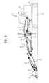
- Fig. 2 shows a hydraulic excavator 1 as an example of a working machine.
- the hydraulic excavator 1 includes a boom of a working machine according to an embodiment of the present invention.
- the hydraulic excavator 1 includes a lower travelling body 3 provided with a crawler 2 and an upper rotating body 4 that is rotatably supported by the lower travelling body 3.
- the upper rotating body 4 includes a boom foot 5 on which a lower end of a main boom member 6, which corresponds to a first boom member, and lower ends of main boom cylinders 7 are supported.
- the main boom cylinders 7 allow the main boom member 6 to be raised and lowered by being pivoted about a boom foot pin 5a, which corresponds to a first-boom member base-end pin.
- the main boom member 6 is provided with hook pins 6a that horizontally project therefrom in the left-right directions.
- a base end of the main front boom member 8 is engaged with the hook pins 6a.
- the main boom member 6 is also provided with boss portions 6b that horizontally project therefrom in the left-right directions. Cylinder pins 7a that support upper ends of the main boom cylinders 7 are inserted through the respective boss portions 6b.
- boom members can be connected to a distal end of the main boom member 6.
- the main front boom member 8 which corresponds to a second boom member, is attached to the distal end of the main boom member 6 in a non-rotatable manner.
- the intermediate boom member 9 can be folded and unfolded by a boom cylinder 11.
- a lower end of an arm cylinder 12 is connected to a back surface of the intermediate boom member 9 such that the arm cylinder 12 is rotatable.
- a base end of an arm 13 is rotatably supported by a distal end of the intermediate boom member 9, and an upper end of the arm cylinder 12 is rotatably connected to the base end of the arm 13. Accordingly, the intermediate boom member 9 and the arm 13 are connected to each other such that the intermediate boom member 9 and the arm 13 can rotate relative to each other.
- a base end of a bucket 14 is connected to a distal end of the arm 13 such that the bucket 14 is rotatable.
- a bucket link 16 is connected to the base end of the bucket 14 and the distal end of the arm 13.
- a distal end of a bucket cylinder 15 is connected to the bucket link 16. Accordingly, the bucket 14 is connected to the arm 13 such that the bucket 14 can rotate relative to the arm 13.
- the main front boom member 8 includes a pair of side plates 20 which sandwich the distal end of the main boom member 6 from both sides thereof in a horizontal direction at the base end of the main front boom member 8.
- Each side plate 20 includes a boss-shaped horizontal-shaft insertion section 20a having a through hole.
- the boom connection pin 10 connected to the above-described intermediate boom member 9 is inserted through the pair of horizontal-shaft insertion sections 20a at the left and right sides.
- each side plate 20 includes a pair of connection-pin insertion sections 20b through which connection pins 22 for connecting the side plate 20 to the main boom member 6 are inserted.
- the horizontal-shaft insertion section 20a and the pair of connection-pin insertion sections 20b in each side plate 20 are arranged in the shape of a triangle in a side view.
- the pair of side plates 20 are provided with claw-shaped hooks 20c formed at an end opposite to the horizontal-shaft insertion sections 20a (at the main-boom member-6 side).
- the hooks 20c are engaged with the above-described hook pins 6a.
- Portions of the pair of side plates 20 at the main-boom member-6 side are cut in a rounded shape so as to continue from the hooks 20c and extend around the boss portions 6b of the main boom member 6. As shown only in Fig.
- the boom connection pin 10 and the connection pins 22 are provided with a rotation restraining member 10a and rotation restraining members 22a, respectively.
- Blocks 8a are provided so as to project from a surface of the main front boom member 8 to prevent the rotation restraining members 10a and 22a from rotating.
- a rigid member 23 which connects the pair of side plates 20 to each other in the horizontal direction is welded to each side plate 20 in an area surrounded by the horizontal-shaft insertion section 20a and the pair of connection-pin insertion sections 20b.
- the rigid member 23 includes a rigid-member main body 23a and a rigid-member extending section 23b.
- the rigid-member main body 23a connects the pair of side plates 20 to each other at a position between the horizontal-shaft insertion sections 20a and the connection-pin insertion sections 20b.
- the rigid-member extending section 23b continues from the rigid-member main body 23a and connects the pair of side plates 20 to each other at a front-surface side of the main boom member 6.
- the rigid-member main body 23a and the rigid-member extending section 23b may be formed by bending a single steel plate or be welded to each other.
- a first reinforcing plate 23c is welded to the rigid-member main body 23a at the horizontal-shaft-insertion-section-20a side thereof.
- the first reinforcing plate 23c is bent toward the pair of connection-pin insertion sections 20b at both ends thereof.
- a closed cross-section portion 25 is formed in an area surrounded by the first reinforcing plate 23c, the rigid-member main body 23a, and the pair of side plates 20.
- the rigid-member extending section 23b continues from the rigid-member main body 23a and extends around the connection-pin insertion sections 20b at the front side in a direction away from the horizontal-shaft insertion sections 20a. Then, the rigid-member extending section 23b is bent so as to extend in a direction away from the connection-pin insertion sections 20b at the front side.
- a cylinder attachment part 26 is welded to the rigid-member extending section 23b and the first reinforcing plate 23c.
- the cylinder attachment part 26 includes a pair of ribs 26a which are spaced from each other in the horizontal direction and which are welded to the rigid-member extending section 23b and the first reinforcing plate 23c so as to continuously extend therealong.
- Each of the ribs 26a is provided with a boss portion 26b.
- the cylinder supporting pin 27 is disposed closer to the main boom member 6 than the closed cross-section portion 25 along a linear direction that connects the boom foot pin 5a at the base end of the main boom member 6 and the horizontal-shaft insertion sections 20a. More specifically, in the case where the boom foot pin 5a is viewed from the horizontal-shaft insertion sections 20a, although the cylinder supporting pin 27 and the closed cross-section portion 25 may have portions at the same distance from the horizontal-shaft insertion sections 20a, at least a portion of the cylinder supporting pin 27 is closer to the main boom member 6 (to the boom foot pin 5a) than the closed cross-section portion 25. This arrangement can be provided since the side plates 20 include side-plate extending sections 21 which expand rearward.
- a load applied to the cylinder attachment part 26 is transmitted to the connection pins 22 through the rigid-member extending section 23b and the side-plate extending sections 21. A part of the load is also transmitted to the closed cross-section portion 25.
- a second reinforcing plate 23d is welded to the rigid-member extending section 23b at the side opposite to the cylinder attachment part 26.
- the second reinforcing plate 23d is bent in a V shape in a side view.
- a second closed cross-section portion 29 is formed in an area surrounded by the second reinforcing plate 23d, the pair of side plates 20, and the rigid-member extending section 23b.
- the rigidity of the cylinder attachment part 26, which receives a large load, is further increased by the second closed cross-section portion 29.
- the shape of the rigid-member extending section 23b is not limited to the V-shape, and may also be an angular U-shape, a semicircular shape, etc., in a side view.
- the components attached to the main boom member 6 at the upper side thereof can be replaced by removing the main front boom member 8 from the main boom member 6 without detaching the boom cylinder 11 from the cylinder attachment part 26.
- various types of boom members such as an ultra-long attachment, a separate boom member, etc., may be attached in place of the bucket boom member as in the present embodiment.
- the distal end of the main boom member 6 is sandwiched from both sides thereof in the horizontal direction by the pair of side plates 20 of the main front boom member 8.
- the pair of side plates 20 are connected to each other in the horizontal direction by the rigid member 23, so that the closed cross-section portion 25 is formed by the rigid member 23 and the pair of side plates 20 and the rigidity is ensured.
- the cylinder attachment part 26 is supported by the side-plate extending sections 21 formed by extending the side plates 20.
- the side plates 20 are extended in a direction away from the boom connection pin 10 along an axial direction of the boom cylinder 11 within a limited space, so that the load applied to the cylinder supporting pin 27 can be effectively supported.
- Fig. 6 shows a first modification of the embodiment according to the present invention.
- the first modification basically differs from the above-described embodiment in that the rigid-member extending section 23b is not provided.
- components similar to those shown in Figs. 1 to 5 are denoted by the same reference numerals, and detailed explanations thereof are thus omitted.
- a rigid member 123 includes only a portion corresponding to the rigid-member main body 23a according to the above-described embodiment.
- the closed cross-section portion 25 is formed by this portion and the first reinforcing plate 23c.
- a side-plate connecting part 125 composed of a circular pipe that extends in the left-right directions is welded to the side-plate extending sections 21.
- a pair of ribs 126a are welded to the side-plate connecting part 125 at the left and right sides, and each rib 126b is provided with a boss portion 126b.
- a cylinder attachment part 126 is formed of the ribs 126a and the boss portions 126b.
- the cylinder supporting pin 27 is inserted through the boss portions 126b while one end of the boom cylinder 11 is placed between the boss portions 126b.
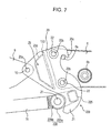
- Fig. 7 shows a second modification of the embodiment according to the present invention.
- the second modification basically differs from the above-described first modification in that a side-plate connecting part 225 composed of a rectangular pipe is provided.
- a cylinder attachment part 226 is formed of ribs 226a and portions 226b. Accordingly, similar to the first modification, the strength can be effectively ensured within a limited space.
- the boss portions may also be directly welded to the side-plate extending sections 21 so that the boss portions function as a side-plate connecting part. Also in this case, the load applied to the boom cylinder 11 can be transmitted to the side-plate extending sections 21. Also in this modification, similar to the first and second modifications, the strength can be effectively ensured in a limited space.
- the main boom member 6 is provided as the first boom member
- the main front boom member 8 is provided as the second boom member
- the intermediate boom member 9 is provided as the third boom member.
- the first boom member may be a connecting boom member connected to the main boom member, and a backhoe attachment, which includes a bucket 14 that faces upward, or a crusher may be attached to the distal end of the boom member.
- the third boom member may also be an arm.
Landscapes
- Engineering & Computer Science (AREA)
- Structural Engineering (AREA)
- Mechanical Engineering (AREA)
- Mining & Mineral Resources (AREA)
- Civil Engineering (AREA)
- General Engineering & Computer Science (AREA)
- Shovels (AREA)
- Component Parts Of Construction Machinery (AREA)
Abstract
Description
- The present invention relates to a boom attached to a working machine, such as a demolition machine, as a working attachment.
- An example of a boom of a working machine includes a main boom member supported on an upper rotating body of the working machine such that the main boom member can be raised and lowered. In the working machine, components can be detachably attached to the main boom member.
- Japanese Registered Utility Model No.
2535667 - More specifically, as shown in
Figs. 8 and9 , in this type of working machine, a base end of asecond boom member 108 is inserted between a pair ofside plates 120 of afirst boom member 106, and is connected to thefirst boom member 106 withconnection pins 122. Aboom cylinder 111 for folding and unfolding thesecond boom member 108 and a third boom member (not shown) with respect to each other is rotatably supported by acylinder attachment part 126. Thecylinder attachment part 126 is provided at a front side of thesecond boom member 108, which has a closed cross-section structure (box-shaped structure) with a high rigidity. - However, there may be a case where the base end of the second boom member cannot be inserted between the pair of side plates of the first boom member because the working machine is small and sufficient space cannot be provided or because of the detaching/attaching structure.
- In such a case, a distal end of the first boom member must be inserted between a pair of side plates of the second boom member. Therefore, it is difficult to provide the cylinder attachment part on the second boom member from the viewpoint of space and rigidity.
- An object of the present invention is to provide a boom of a working machine in which a cylinder attachment part can be provided on a second boom member without reducing the rigidity even when a base end of the second boom member cannot be inserted between a pair of side plates of a first boom member.
- To achieve the above-described object, according to the present invention, a cylinder attachment part is provided on a rigid member which connects a pair of side plates included in the second boom member to each other.
- According to the present invention, a boom of a working machine includes at least a first boom member, a second boom member, and a third boom member, a base end of the first boom member being attached to a main body of the working machine with a first-boom member base-end pin such that the first boom member is capable of swinging vertically, a distal end of the first boom member being connected to the second boom member, the second boom member and the third boom member being connected to each other such that the second boom member and the third boom member are rotatable relative to each other about a horizontal shaft, the second boom member and the third boom member being folded and unfolded relative to each other by a boom cylinder.
- The second boom member includes a pair of side plates configured to sandwich the distal end of the first boom member from both sides of the first boom member in a horizontal direction at base ends of the side plates, a rigid member configured to connect the pair of side plates to each other in the horizontal direction, a closed cross-section portion surrounded by the rigid member and the side plates, horizontal-shaft insertion sections which are provided on the pair of side plates and through which the horizontal shaft extends, connection-pin insertion sections which are provided on the pair of side plates and through which a connection pin for connecting the first boom member to the side plates extends, side-plate extending sections included in the pair of side plates and extending from the connection-pin insertion sections in a direction away from the horizontal shaft, and a cylinder attachment part which is provided on the side-plate extending sections and through which a cylinder supporting pin extends, the cylinder supporting pin supporting one end of the boom cylinder such that the boom cylinder is rotatable. At least a portion of the cylinder supporting pin is disposed closer to the first boom member than the closed cross-section portion in a linear direction connecting the first-boom member base-end pin and the horizontal-shaft insertion sections.
- According to this structure, when the base end of the second boom member cannot be inserted between a pair of side plates included in the first boom member and it is difficult to arrange the cylinder supporting pin because the working machine is small and sufficient space cannot be provided or because of the detaching/attaching structure, the distal end of the first boom member is sandwiched from both sides thereof in the horizontal direction by the pair of side plates of the second boom member. The pair of side plates are connected to each other in the horizontal direction by the rigid member, so that the closed cross-section portion is formed by the rigid member and the pair of side plates and the rigidity is ensured. In addition, the load applied to the boom cylinder when the cylinder is expanded or contracted is supported by the side-plate extending sections formed by extending the side plates. Therefore, a sufficient strength can be ensured in a limited space. In addition, since the cylinder attachment part is provided on the second boom member, the second and third boom members can be separated from the first boom member without detaching the boom cylinder from the cylinder attachment part. Here, "at least a portion of the cylinder supporting pin is ..." means that the first-boom member base-end pin and the closed cross-section portion may have portions at the same distance from the horizontal-shaft insertion section in the linear direction connecting the first-boom member base-end pin and the horizontal-shaft insertion sections.
- In the above-described structure, preferably, the cylinder attachment part is connected to a side-plate connecting part configured to connect the left and right side-plate extending sections, and at least a part of load applied to the boom cylinder is received by the side-plate connecting part.
- With this structure, at least a part of the load applied to the boom cylinder is received by the side-plate connecting part, and is transmitted to the side-plate extending sections. Therefore, the strength can be effectively ensured within a limited space.
- In addition, according to the present invention, in any of the above-described structures, preferably, the rigid member includes a rigid-member main body configured to connect the pair of side plates to each other at a position between the horizontal-shaft insertion sections and the connection-pin insertion sections and a rigid-member extending section configured to extend from the rigid-member main body and connect the pair of side plates to each other along a front side of the first boom member. In addition, preferably, the rigid-member main body defines a part of the closed cross-section portion, the rigid-member extending section defines the side-plate connecting part, and the cylinder attachment part is connected so as to extend along the closed cross-section portion and the rigid-member extending section.
- With this structure, a part of the load applied to the cylinder attachment part is transmitted to the closed cross-section portion through the rigid-member extending section. In addition, the rigid-member extending section functions as the side-plate connecting part, and the load applied to the boom cylinder is transmitted also to the rigid member. Therefore, the cylinder attachment part can be more effectively disposed within a limited space.
- According to the present invention, in the above-described structure, preferably, a second closed cross-section portion different from the closed cross-section portion is provided on the side-plate extending sections at the side opposite to the cylinder attachment part.
- With this structure, the rigidity of the cylinder attachment part, which receives a large load, is further increased by the second closed cross-section portion. In addition, since the second closed cross-section portion is provided on the side-plate extending sections, the load applied to the boom cylinder can be more effectively supported in a limited space.
- According to the present invention, in any of the above-described structures, preferably, the first boom member is a main boom member supported on an upper rotating body of the working machine such that the main boom member is capable of being raised and lowered, and the second boom member is a main front boom member connected to the main boom member.
- With this structure, even when the space is limited, as in the case where the working machine is small, the components attached to the main boom member at the upper side thereof can be replaced without detaching the boom cylinder from the cylinder attachment part. Since the first boom member is the main boom member of the working machine and the second boom member is the main front boom member, a high-rigidity boom member which can be easily replaced with another boom member even when the working machine is small can be provided.
-
-
Fig. 1 is an enlarged perspective of a main front boom member and a section surrounding the main front boom member in a boom of a working machine according to an embodiment of the present invention; -
Fig. 2 is a side view illustrating the overall body of a hydraulic excavator; -
Fig. 3 is an enlarged side view illustrating the main front boom member and the section surrounding the main front boom member; -
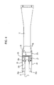
Fig. 4 is an enlarged bottom view illustrating the main front boom member and the section surrounding the main front boom member; -
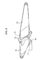
Fig. 5 is an enlarged side view of the main front boom member; -
Fig. 6 is an enlarged side view illustrating a main front boom member and a section surrounding the main front boom member according to a first modification of the embodiment; -
Fig. 7 is an enlarged side view illustrating a main front boom member and a section surrounding the main front boom member according to a second modification of the embodiment; -
Fig. 8 is a side view illustrating a connecting section of a boom of a working machine according to a related art; and -
Fig. 9 is a bottom view illustrating the connecting section of the boom of the working machine according to the related art. - An embodiment of the present invention will be described below with reference to the drawings.
-
Fig. 2 shows a hydraulic excavator 1 as an example of a working machine. The hydraulic excavator 1 includes a boom of a working machine according to an embodiment of the present invention. The hydraulic excavator 1 includes alower travelling body 3 provided with a crawler 2 and an upper rotating body 4 that is rotatably supported by thelower travelling body 3. - The upper rotating body 4 includes a
boom foot 5 on which a lower end of amain boom member 6, which corresponds to a first boom member, and lower ends ofmain boom cylinders 7 are supported. Themain boom cylinders 7 allow themain boom member 6 to be raised and lowered by being pivoted about aboom foot pin 5a, which corresponds to a first-boom member base-end pin. As shown inFigs. 1 ,3 , and4 , themain boom member 6 is provided withhook pins 6a that horizontally project therefrom in the left-right directions. In a process of attaching a mainfront boom member 8 to themain boom member 6, a base end of the mainfront boom member 8 is engaged with thehook pins 6a. Themain boom member 6 is also provided withboss portions 6b that horizontally project therefrom in the left-right directions.Cylinder pins 7a that support upper ends of themain boom cylinders 7 are inserted through therespective boss portions 6b. - Various types of boom members can be connected to a distal end of the
main boom member 6. In the present embodiment, the mainfront boom member 8, which corresponds to a second boom member, is attached to the distal end of themain boom member 6 in a non-rotatable manner. Anintermediate boom member 9, which corresponds to a third boom member, is connected to a distal end of the mainfront boom member 8 such that theintermediate boom member 9 can rotate relative to the mainfront boom member 8 about aboom connection pin 10, which corresponds to a horizontal shaft. Theintermediate boom member 9 can be folded and unfolded by aboom cylinder 11. - As shown in
Fig. 2 , a lower end of anarm cylinder 12 is connected to a back surface of theintermediate boom member 9 such that thearm cylinder 12 is rotatable. A base end of anarm 13 is rotatably supported by a distal end of theintermediate boom member 9, and an upper end of thearm cylinder 12 is rotatably connected to the base end of thearm 13. Accordingly, theintermediate boom member 9 and thearm 13 are connected to each other such that theintermediate boom member 9 and thearm 13 can rotate relative to each other. - A base end of a
bucket 14 is connected to a distal end of thearm 13 such that thebucket 14 is rotatable. Abucket link 16 is connected to the base end of thebucket 14 and the distal end of thearm 13. A distal end of abucket cylinder 15 is connected to thebucket link 16. Accordingly, thebucket 14 is connected to thearm 13 such that thebucket 14 can rotate relative to thearm 13. - As shown in
Figs. 1 ,3 , and4 , the mainfront boom member 8 includes a pair ofside plates 20 which sandwich the distal end of themain boom member 6 from both sides thereof in a horizontal direction at the base end of the mainfront boom member 8. Eachside plate 20 includes a boss-shaped horizontal-shaft insertion section 20a having a through hole. Theboom connection pin 10 connected to the above-describedintermediate boom member 9 is inserted through the pair of horizontal-shaft insertion sections 20a at the left and right sides. In addition, eachside plate 20 includes a pair of connection-pin insertion sections 20b through which connection pins 22 for connecting theside plate 20 to themain boom member 6 are inserted. The horizontal-shaft insertion section 20a and the pair of connection-pin insertion sections 20b in eachside plate 20 are arranged in the shape of a triangle in a side view. The pair ofside plates 20 are provided with claw-shapedhooks 20c formed at an end opposite to the horizontal-shaft insertion sections 20a (at the main-boom member-6 side). Thehooks 20c are engaged with the above-describedhook pins 6a. Portions of the pair ofside plates 20 at the main-boom member-6 side are cut in a rounded shape so as to continue from thehooks 20c and extend around theboss portions 6b of themain boom member 6. As shown only inFig. 1 , theboom connection pin 10 and the connection pins 22 are provided with arotation restraining member 10a androtation restraining members 22a, respectively.Blocks 8a are provided so as to project from a surface of the mainfront boom member 8 to prevent therotation restraining members - A
rigid member 23 which connects the pair ofside plates 20 to each other in the horizontal direction is welded to eachside plate 20 in an area surrounded by the horizontal-shaft insertion section 20a and the pair of connection-pin insertion sections 20b. Therigid member 23 includes a rigid-membermain body 23a and a rigid-member extending section 23b. The rigid-membermain body 23a connects the pair ofside plates 20 to each other at a position between the horizontal-shaft insertion sections 20a and the connection-pin insertion sections 20b. The rigid-member extending section 23b continues from the rigid-membermain body 23a and connects the pair ofside plates 20 to each other at a front-surface side of themain boom member 6. The rigid-membermain body 23a and the rigid-member extending section 23b may be formed by bending a single steel plate or be welded to each other. - A first reinforcing
plate 23c is welded to the rigid-membermain body 23a at the horizontal-shaft-insertion-section-20a side thereof. The first reinforcingplate 23c is bent toward the pair of connection-pin insertion sections 20b at both ends thereof. Aclosed cross-section portion 25 is formed in an area surrounded by the first reinforcingplate 23c, the rigid-membermain body 23a, and the pair ofside plates 20. - The rigid-
member extending section 23b continues from the rigid-membermain body 23a and extends around the connection-pin insertion sections 20b at the front side in a direction away from the horizontal-shaft insertion sections 20a. Then, the rigid-member extending section 23b is bent so as to extend in a direction away from the connection-pin insertion sections 20b at the front side. Acylinder attachment part 26 is welded to the rigid-member extending section 23b and the first reinforcingplate 23c. Thecylinder attachment part 26 includes a pair ofribs 26a which are spaced from each other in the horizontal direction and which are welded to the rigid-member extending section 23b and the first reinforcingplate 23c so as to continuously extend therealong. Each of theribs 26a is provided with aboss portion 26b. Acylinder supporting pin 27, which supports an end (tube-side end in the present embodiment) of theboom cylinder 11 such that theboom cylinder 11 is rotatable, is inserted through theboss portions 26b. - Referring to
Fig. 3 , according to the present embodiment, at least a portion of thecylinder supporting pin 27 is disposed closer to themain boom member 6 than theclosed cross-section portion 25 along a linear direction that connects theboom foot pin 5a at the base end of themain boom member 6 and the horizontal-shaft insertion sections 20a. More specifically, in the case where theboom foot pin 5a is viewed from the horizontal-shaft insertion sections 20a, although thecylinder supporting pin 27 and theclosed cross-section portion 25 may have portions at the same distance from the horizontal-shaft insertion sections 20a, at least a portion of thecylinder supporting pin 27 is closer to the main boom member 6 (to theboom foot pin 5a) than theclosed cross-section portion 25. This arrangement can be provided since theside plates 20 include side-plate extending sections 21 which expand rearward. - A load applied to the
cylinder attachment part 26 is transmitted to the connection pins 22 through the rigid-member extending section 23b and the side-plate extending sections 21. A part of the load is also transmitted to theclosed cross-section portion 25. - A second reinforcing
plate 23d is welded to the rigid-member extending section 23b at the side opposite to thecylinder attachment part 26. The second reinforcingplate 23d is bent in a V shape in a side view. A secondclosed cross-section portion 29 is formed in an area surrounded by the second reinforcingplate 23d, the pair ofside plates 20, and the rigid-member extending section 23b. The rigidity of thecylinder attachment part 26, which receives a large load, is further increased by the secondclosed cross-section portion 29. The shape of the rigid-member extending section 23b is not limited to the V-shape, and may also be an angular U-shape, a semicircular shape, etc., in a side view. - In the above-described structure, the components attached to the
main boom member 6 at the upper side thereof can be replaced by removing the mainfront boom member 8 from themain boom member 6 without detaching theboom cylinder 11 from thecylinder attachment part 26. In the hydraulic excavator 1, various types of boom members, such as an ultra-long attachment, a separate boom member, etc., may be attached in place of the bucket boom member as in the present embodiment. - In the present embodiment, when the base end of the main
front boom member 8 cannot be inserted between a pair ofside plates 20 included in themain boom member 6 because the working machine is small and sufficient space cannot be provided or because of the detaching/attaching structure, the distal end of themain boom member 6 is sandwiched from both sides thereof in the horizontal direction by the pair ofside plates 20 of the mainfront boom member 8. The pair ofside plates 20 are connected to each other in the horizontal direction by therigid member 23, so that theclosed cross-section portion 25 is formed by therigid member 23 and the pair ofside plates 20 and the rigidity is ensured. In addition, thecylinder attachment part 26 is supported by the side-plate extending sections 21 formed by extending theside plates 20. Thus, theside plates 20 are extended in a direction away from theboom connection pin 10 along an axial direction of theboom cylinder 11 within a limited space, so that the load applied to thecylinder supporting pin 27 can be effectively supported. First Modification of Embodiment -
Fig. 6 shows a first modification of the embodiment according to the present invention. The first modification basically differs from the above-described embodiment in that the rigid-member extending section 23b is not provided. In the following explanation of the embodiments, components similar to those shown inFigs. 1 to 5 are denoted by the same reference numerals, and detailed explanations thereof are thus omitted. - In this modification, a
rigid member 123 includes only a portion corresponding to the rigid-membermain body 23a according to the above-described embodiment. Theclosed cross-section portion 25 is formed by this portion and the first reinforcingplate 23c. - In addition, a side-
plate connecting part 125 composed of a circular pipe that extends in the left-right directions is welded to the side-plate extending sections 21. - A pair of
ribs 126a are welded to the side-plate connecting part 125 at the left and right sides, and eachrib 126b is provided with aboss portion 126b. Acylinder attachment part 126 is formed of theribs 126a and theboss portions 126b. Thecylinder supporting pin 27 is inserted through theboss portions 126b while one end of theboom cylinder 11 is placed between theboss portions 126b. - With this structure, at least a part of the load applied to the
boom cylinder 11 is received by the side-plate connecting part 125. This load is transmitted to the connection pins 22 through the side-plate extending sections 21. - Therefore, also in this modification, the strength can be effectively ensured in a limited space.
-
Fig. 7 shows a second modification of the embodiment according to the present invention. The second modification basically differs from the above-described first modification in that a side-plate connecting part 225 composed of a rectangular pipe is provided. - Also in this case, a
cylinder attachment part 226 is formed ofribs 226a andportions 226b. Accordingly, similar to the first modification, the strength can be effectively ensured within a limited space. - Although not shown in the figures, the boss portions may also be directly welded to the side-
plate extending sections 21 so that the boss portions function as a side-plate connecting part. Also in this case, the load applied to theboom cylinder 11 can be transmitted to the side-plate extending sections 21. Also in this modification, similar to the first and second modifications, the strength can be effectively ensured in a limited space. - According to the present invention, the above-described embodiment can be changed as follows.
- That is, according to the above-described embodiment, the
main boom member 6 is provided as the first boom member, the mainfront boom member 8 is provided as the second boom member, and theintermediate boom member 9 is provided as the third boom member. However, the present invention is not limited to this structure. For example, the first boom member may be a connecting boom member connected to the main boom member, and a backhoe attachment, which includes abucket 14 that faces upward, or a crusher may be attached to the distal end of the boom member. In addition, the third boom member may also be an arm. - Although the invention has been described with reference to the preferred embodiments in the attached figures, it is noted that equivalents may be employed and substitutions made herein without departing from the scope of the invention as recited in the claims.
Claims (5)
- A boom of a working machine, the boom including at least a first boom member, a second boom member, and a third boom member, a base end of the first boom member being attached to a main body of the working machine with a first-boom member base-end pin such that the first boom member is capable of swinging vertically, a distal end of the first boom member being connected to the second boom member, the second boom member and the third boom member being connected to each other such that the second boom member and the third boom member are rotatable relative to each other about a horizontal shaft, the second boom member and the third boom member being folded and unfolded relative to each other by a boom cylinder,
wherein the second boom member includes
a pair of side plates configured to sandwich the distal end of the first boom member from both sides of the first boom member in a horizontal direction at base ends of the side plates,
a rigid member configured to connect the pair of side plates to each other in the horizontal direction,
a closed cross-section portion surrounded by the rigid member and the side plates,
horizontal-shaft insertion sections which are provided on the pair of side plates and through which the horizontal shaft extends,
connection-pin insertion sections which are provided on the pair of side plates and through which a connection pin for connecting the first boom member to the side plates extends,
side-plate extending sections included in the pair of side plates and extending from the connection-pin insertion sections in a direction away from the horizontal shaft, and
a cylinder attachment part which is provided on the side-plate extending sections and through which a cylinder supporting pin extends, the cylinder supporting pin supporting one end of the boom cylinder such that the boom cylinder is rotatable,
wherein at least a portion of the cylinder supporting pin is disposed closer to the first boom member than the closed cross-section portion in a linear direction connecting the first-boom member base-end pin and the horizontal-shaft insertion sections. - The boom of the working machine according to claim 1,
wherein the cylinder attachment part is connected to a side-plate connecting part configured to connect the left and right side-plate extending sections, and at least a part of load applied to the boom cylinder is received by the side-plate connecting part. - The boom of the working machine according to claim 2,
wherein the rigid member includes
a rigid-member main body configured to connect the pair of side plates to each other at a position between the horizontal-shaft insertion sections and the connection-pin insertion sections, and
a rigid-member extending section configured to extend from the rigid-member main body and connect the pair of side plates to each other along a front side of the first boom member,
wherein the rigid-member main body defines a part of the closed cross-section portion,
wherein the rigid-member extending section defines the side-plate connecting part, and
wherein the cylinder attachment part is connected so as to extend along the closed cross-section portion and the rigid-member extending section. - The boom of the working machine according to claim 3,
wherein a second closed cross-section portion different from the closed cross-section portion is provided on the side-plate extending sections at the side opposite to the cylinder attachment part. - The boom of the working machine according to one of claims 1 to 4,
wherein the first boom member is a main boom member supported on an upper rotating body of the working machine such that the main boom member is capable of being raised and lowered, and
wherein the second boom member is a main front boom member connected to the main boom member.
Applications Claiming Priority (1)
| Application Number | Priority Date | Filing Date | Title |
|---|---|---|---|
| JP2009008188A JP4798228B2 (en) | 2009-01-16 | 2009-01-16 | Work machine boom |
Publications (3)
| Publication Number | Publication Date |
|---|---|
| EP2208827A2 true EP2208827A2 (en) | 2010-07-21 |
| EP2208827A3 EP2208827A3 (en) | 2014-04-23 |
| EP2208827B1 EP2208827B1 (en) | 2015-12-23 |
Family
ID=42082619
Family Applications (1)
| Application Number | Title | Priority Date | Filing Date |
|---|---|---|---|
| EP10150759.8A Not-in-force EP2208827B1 (en) | 2009-01-16 | 2010-01-14 | Boom of a working machine |
Country Status (2)
| Country | Link |
|---|---|
| EP (1) | EP2208827B1 (en) |
| JP (1) | JP4798228B2 (en) |
Cited By (2)
| Publication number | Priority date | Publication date | Assignee | Title |
|---|---|---|---|---|
| WO2012097158A3 (en) * | 2011-01-13 | 2012-09-13 | Ramun John R | Modular system for connecting attachments to a construction machine |
| US8539699B2 (en) | 2006-01-13 | 2013-09-24 | John R. Ramun | Modular system for connecting attachments to a construction machine |
Families Citing this family (2)
| Publication number | Priority date | Publication date | Assignee | Title |
|---|---|---|---|---|
| JP5939343B2 (en) * | 2015-08-12 | 2016-06-22 | コベルコ建機株式会社 | Work machine boom |
| CN118933106B (en) * | 2024-08-20 | 2026-04-14 | 中联重科土方机械有限公司 | Working machine boom front support and working machine |
Citations (1)
| Publication number | Priority date | Publication date | Assignee | Title |
|---|---|---|---|---|
| JP2535667B2 (en) | 1990-11-20 | 1996-09-18 | 富士通株式会社 | Handling mechanism |
Family Cites Families (6)
| Publication number | Priority date | Publication date | Assignee | Title |
|---|---|---|---|---|
| US3589539A (en) * | 1969-06-27 | 1971-06-29 | Hein Werner Corp | Backhoe having an articulated gooseneck boom |
| DE4328449A1 (en) * | 1993-08-24 | 1995-03-02 | Macmoter Spa | Construction machine, in particular excavator vehicle |
| DE4498218T1 (en) * | 1993-10-27 | 1996-12-05 | Komatsu Mfg Co Ltd | Working machine of a hydraulic excavator |
| JP3540541B2 (en) * | 1996-01-30 | 2004-07-07 | 日立建機株式会社 | Swing hydraulic excavator |
| JP4042907B2 (en) * | 2003-05-30 | 2008-02-06 | 日立建機株式会社 | Work equipment front device and work equipment |
| JP5223276B2 (en) * | 2006-10-31 | 2013-06-26 | 尼崎重機株式会社 | Boom and front attachment of work machine |
-
2009
- 2009-01-16 JP JP2009008188A patent/JP4798228B2/en not_active Expired - Fee Related
-
2010
- 2010-01-14 EP EP10150759.8A patent/EP2208827B1/en not_active Not-in-force
Patent Citations (1)
| Publication number | Priority date | Publication date | Assignee | Title |
|---|---|---|---|---|
| JP2535667B2 (en) | 1990-11-20 | 1996-09-18 | 富士通株式会社 | Handling mechanism |
Cited By (2)
| Publication number | Priority date | Publication date | Assignee | Title |
|---|---|---|---|---|
| US8539699B2 (en) | 2006-01-13 | 2013-09-24 | John R. Ramun | Modular system for connecting attachments to a construction machine |
| WO2012097158A3 (en) * | 2011-01-13 | 2012-09-13 | Ramun John R | Modular system for connecting attachments to a construction machine |
Also Published As
| Publication number | Publication date |
|---|---|
| EP2208827A3 (en) | 2014-04-23 |
| JP2010163821A (en) | 2010-07-29 |
| JP4798228B2 (en) | 2011-10-19 |
| EP2208827B1 (en) | 2015-12-23 |
Similar Documents
| Publication | Publication Date | Title |
|---|---|---|
| CN106948392B (en) | Boom of working machine and working machine | |
| EP2354327B1 (en) | Working machine | |
| JP2007162454A (en) | Counterweight attachment / detachment device | |
| EP2208827B1 (en) | Boom of a working machine | |
| JP4920022B2 (en) | Swivel construction machine | |
| JP5189011B2 (en) | Construction machine swivel frame | |
| JP4940189B2 (en) | Backhoe boom structure | |
| JP6013286B2 (en) | Work equipment boom | |
| EP2290163A1 (en) | Construction machine | |
| JP6260284B2 (en) | Construction machinery side frame | |
| JP3697367B2 (en) | Work equipment | |
| EP1775393A1 (en) | Protective structure for a cabin of a workmachine | |
| JP2008201328A (en) | Tractor rear work machine mounting frame structure. | |
| JP3398283B2 (en) | Power shovel | |
| JP4535092B2 (en) | Construction machinery | |
| JP4299952B2 (en) | Folding arm of work machine | |
| WO2008053779A1 (en) | Boom and front attachment for working machine | |
| JP3998091B2 (en) | Construction machinery boom | |
| JP4444606B2 (en) | Construction machinery | |
| JP4351841B2 (en) | Construction machine swivel frame | |
| JP5466672B2 (en) | Front device for construction machine and its mounting table | |
| JP2013170582A (en) | Cylinder device | |
| JP7401418B2 (en) | construction machinery | |
| JPH1136357A (en) | Crane device for hydraulic shovel | |
| JP2006045976A (en) | Construction machine |
Legal Events
| Date | Code | Title | Description |
|---|---|---|---|
| PUAI | Public reference made under article 153(3) epc to a published international application that has entered the european phase |
Free format text: ORIGINAL CODE: 0009012 |
|
| 17P | Request for examination filed |
Effective date: 20100114 |
|
| AK | Designated contracting states |
Kind code of ref document: A2 Designated state(s): AT BE BG CH CY CZ DE DK EE ES FI FR GB GR HR HU IE IS IT LI LT LU LV MC MK MT NL NO PL PT RO SE SI SK SM TR |
|
| AX | Request for extension of the european patent |
Extension state: AL BA RS |
|
| PUAL | Search report despatched |
Free format text: ORIGINAL CODE: 0009013 |
|
| AK | Designated contracting states |
Kind code of ref document: A3 Designated state(s): AT BE BG CH CY CZ DE DK EE ES FI FR GB GR HR HU IE IS IT LI LT LU LV MC MK MT NL NO PL PT RO SE SI SK SM TR |
|
| AX | Request for extension of the european patent |
Extension state: AL BA RS |
|
| RIC1 | Information provided on ipc code assigned before grant |
Ipc: E02F 3/36 20060101ALI20140318BHEP Ipc: E02F 3/96 20060101ALI20140318BHEP Ipc: E02F 3/32 20060101ALI20140318BHEP Ipc: E02F 3/30 20060101AFI20140318BHEP |
|
| GRAP | Despatch of communication of intention to grant a patent |
Free format text: ORIGINAL CODE: EPIDOSNIGR1 |
|
| INTG | Intention to grant announced |
Effective date: 20150717 |
|
| GRAS | Grant fee paid |
Free format text: ORIGINAL CODE: EPIDOSNIGR3 |
|
| GRAA | (expected) grant |
Free format text: ORIGINAL CODE: 0009210 |
|
| AK | Designated contracting states |
Kind code of ref document: B1 Designated state(s): AT BE BG CH CY CZ DE DK EE ES FI FR GB GR HR HU IE IS IT LI LT LU LV MC MK MT NL NO PL PT RO SE SI SK SM TR |
|
| REG | Reference to a national code |
Ref country code: GB Ref legal event code: FG4D |
|
| REG | Reference to a national code |
Ref country code: CH Ref legal event code: EP |
|
| REG | Reference to a national code |
Ref country code: IE Ref legal event code: FG4D |
|
| REG | Reference to a national code |
Ref country code: AT Ref legal event code: REF Ref document number: 766629 Country of ref document: AT Kind code of ref document: T Effective date: 20160115 |
|
| REG | Reference to a national code |
Ref country code: FR Ref legal event code: PLFP Year of fee payment: 7 |
|
| REG | Reference to a national code |
Ref country code: DE Ref legal event code: R096 Ref document number: 602010029633 Country of ref document: DE |
|
| REG | Reference to a national code |
Ref country code: LT Ref legal event code: MG4D |
|
| REG | Reference to a national code |
Ref country code: NL Ref legal event code: MP Effective date: 20151223 |
|
| PG25 | Lapsed in a contracting state [announced via postgrant information from national office to epo] |
Ref country code: HR Free format text: LAPSE BECAUSE OF FAILURE TO SUBMIT A TRANSLATION OF THE DESCRIPTION OR TO PAY THE FEE WITHIN THE PRESCRIBED TIME-LIMIT Effective date: 20151223 Ref country code: LT Free format text: LAPSE BECAUSE OF FAILURE TO SUBMIT A TRANSLATION OF THE DESCRIPTION OR TO PAY THE FEE WITHIN THE PRESCRIBED TIME-LIMIT Effective date: 20151223 Ref country code: NO Free format text: LAPSE BECAUSE OF FAILURE TO SUBMIT A TRANSLATION OF THE DESCRIPTION OR TO PAY THE FEE WITHIN THE PRESCRIBED TIME-LIMIT Effective date: 20160323 |
|
| REG | Reference to a national code |
Ref country code: AT Ref legal event code: MK05 Ref document number: 766629 Country of ref document: AT Kind code of ref document: T Effective date: 20151223 |
|
| PG25 | Lapsed in a contracting state [announced via postgrant information from national office to epo] |
Ref country code: BE Free format text: LAPSE BECAUSE OF NON-PAYMENT OF DUE FEES Effective date: 20160131 Ref country code: NL Free format text: LAPSE BECAUSE OF FAILURE TO SUBMIT A TRANSLATION OF THE DESCRIPTION OR TO PAY THE FEE WITHIN THE PRESCRIBED TIME-LIMIT Effective date: 20151223 Ref country code: LV Free format text: LAPSE BECAUSE OF FAILURE TO SUBMIT A TRANSLATION OF THE DESCRIPTION OR TO PAY THE FEE WITHIN THE PRESCRIBED TIME-LIMIT Effective date: 20151223 Ref country code: SE Free format text: LAPSE BECAUSE OF FAILURE TO SUBMIT A TRANSLATION OF THE DESCRIPTION OR TO PAY THE FEE WITHIN THE PRESCRIBED TIME-LIMIT Effective date: 20151223 Ref country code: GR Free format text: LAPSE BECAUSE OF FAILURE TO SUBMIT A TRANSLATION OF THE DESCRIPTION OR TO PAY THE FEE WITHIN THE PRESCRIBED TIME-LIMIT Effective date: 20160324 Ref country code: FI Free format text: LAPSE BECAUSE OF FAILURE TO SUBMIT A TRANSLATION OF THE DESCRIPTION OR TO PAY THE FEE WITHIN THE PRESCRIBED TIME-LIMIT Effective date: 20151223 |
|
| PG25 | Lapsed in a contracting state [announced via postgrant information from national office to epo] |
Ref country code: CZ Free format text: LAPSE BECAUSE OF FAILURE TO SUBMIT A TRANSLATION OF THE DESCRIPTION OR TO PAY THE FEE WITHIN THE PRESCRIBED TIME-LIMIT Effective date: 20151223 Ref country code: ES Free format text: LAPSE BECAUSE OF FAILURE TO SUBMIT A TRANSLATION OF THE DESCRIPTION OR TO PAY THE FEE WITHIN THE PRESCRIBED TIME-LIMIT Effective date: 20151223 |
|
| PG25 | Lapsed in a contracting state [announced via postgrant information from national office to epo] |
Ref country code: PT Free format text: LAPSE BECAUSE OF FAILURE TO SUBMIT A TRANSLATION OF THE DESCRIPTION OR TO PAY THE FEE WITHIN THE PRESCRIBED TIME-LIMIT Effective date: 20160426 Ref country code: IS Free format text: LAPSE BECAUSE OF FAILURE TO SUBMIT A TRANSLATION OF THE DESCRIPTION OR TO PAY THE FEE WITHIN THE PRESCRIBED TIME-LIMIT Effective date: 20160423 Ref country code: AT Free format text: LAPSE BECAUSE OF FAILURE TO SUBMIT A TRANSLATION OF THE DESCRIPTION OR TO PAY THE FEE WITHIN THE PRESCRIBED TIME-LIMIT Effective date: 20151223 Ref country code: EE Free format text: LAPSE BECAUSE OF FAILURE TO SUBMIT A TRANSLATION OF THE DESCRIPTION OR TO PAY THE FEE WITHIN THE PRESCRIBED TIME-LIMIT Effective date: 20151223 Ref country code: RO Free format text: LAPSE BECAUSE OF FAILURE TO SUBMIT A TRANSLATION OF THE DESCRIPTION OR TO PAY THE FEE WITHIN THE PRESCRIBED TIME-LIMIT Effective date: 20151223 Ref country code: SM Free format text: LAPSE BECAUSE OF FAILURE TO SUBMIT A TRANSLATION OF THE DESCRIPTION OR TO PAY THE FEE WITHIN THE PRESCRIBED TIME-LIMIT Effective date: 20151223 Ref country code: SK Free format text: LAPSE BECAUSE OF FAILURE TO SUBMIT A TRANSLATION OF THE DESCRIPTION OR TO PAY THE FEE WITHIN THE PRESCRIBED TIME-LIMIT Effective date: 20151223 Ref country code: LU Free format text: LAPSE BECAUSE OF FAILURE TO SUBMIT A TRANSLATION OF THE DESCRIPTION OR TO PAY THE FEE WITHIN THE PRESCRIBED TIME-LIMIT Effective date: 20160114 Ref country code: PL Free format text: LAPSE BECAUSE OF FAILURE TO SUBMIT A TRANSLATION OF THE DESCRIPTION OR TO PAY THE FEE WITHIN THE PRESCRIBED TIME-LIMIT Effective date: 20151223 |
|
| REG | Reference to a national code |
Ref country code: CH Ref legal event code: PL |
|
| REG | Reference to a national code |
Ref country code: DE Ref legal event code: R097 Ref document number: 602010029633 Country of ref document: DE |
|
| PG25 | Lapsed in a contracting state [announced via postgrant information from national office to epo] |
Ref country code: MC Free format text: LAPSE BECAUSE OF FAILURE TO SUBMIT A TRANSLATION OF THE DESCRIPTION OR TO PAY THE FEE WITHIN THE PRESCRIBED TIME-LIMIT Effective date: 20151223 |
|
| PLBE | No opposition filed within time limit |
Free format text: ORIGINAL CODE: 0009261 |
|
| STAA | Information on the status of an ep patent application or granted ep patent |
Free format text: STATUS: NO OPPOSITION FILED WITHIN TIME LIMIT |
|
| PG25 | Lapsed in a contracting state [announced via postgrant information from national office to epo] |
Ref country code: CH Free format text: LAPSE BECAUSE OF NON-PAYMENT OF DUE FEES Effective date: 20160131 Ref country code: LI Free format text: LAPSE BECAUSE OF NON-PAYMENT OF DUE FEES Effective date: 20160131 Ref country code: DK Free format text: LAPSE BECAUSE OF FAILURE TO SUBMIT A TRANSLATION OF THE DESCRIPTION OR TO PAY THE FEE WITHIN THE PRESCRIBED TIME-LIMIT Effective date: 20151223 |
|
| REG | Reference to a national code |
Ref country code: IE Ref legal event code: MM4A |
|
| 26N | No opposition filed |
Effective date: 20160926 |
|
| REG | Reference to a national code |
Ref country code: FR Ref legal event code: PLFP Year of fee payment: 8 |
|
| PG25 | Lapsed in a contracting state [announced via postgrant information from national office to epo] |
Ref country code: BE Free format text: LAPSE BECAUSE OF FAILURE TO SUBMIT A TRANSLATION OF THE DESCRIPTION OR TO PAY THE FEE WITHIN THE PRESCRIBED TIME-LIMIT Effective date: 20151223 |
|
| PG25 | Lapsed in a contracting state [announced via postgrant information from national office to epo] |
Ref country code: IE Free format text: LAPSE BECAUSE OF NON-PAYMENT OF DUE FEES Effective date: 20160114 |
|
| PG25 | Lapsed in a contracting state [announced via postgrant information from national office to epo] |
Ref country code: SI Free format text: LAPSE BECAUSE OF FAILURE TO SUBMIT A TRANSLATION OF THE DESCRIPTION OR TO PAY THE FEE WITHIN THE PRESCRIBED TIME-LIMIT Effective date: 20151223 |
|
| PG25 | Lapsed in a contracting state [announced via postgrant information from national office to epo] |
Ref country code: MT Free format text: LAPSE BECAUSE OF FAILURE TO SUBMIT A TRANSLATION OF THE DESCRIPTION OR TO PAY THE FEE WITHIN THE PRESCRIBED TIME-LIMIT Effective date: 20151223 |
|
| REG | Reference to a national code |
Ref country code: FR Ref legal event code: PLFP Year of fee payment: 9 |
|
| PG25 | Lapsed in a contracting state [announced via postgrant information from national office to epo] |
Ref country code: HU Free format text: LAPSE BECAUSE OF FAILURE TO SUBMIT A TRANSLATION OF THE DESCRIPTION OR TO PAY THE FEE WITHIN THE PRESCRIBED TIME-LIMIT; INVALID AB INITIO Effective date: 20100114 Ref country code: CY Free format text: LAPSE BECAUSE OF FAILURE TO SUBMIT A TRANSLATION OF THE DESCRIPTION OR TO PAY THE FEE WITHIN THE PRESCRIBED TIME-LIMIT Effective date: 20151223 |
|
| PG25 | Lapsed in a contracting state [announced via postgrant information from national office to epo] |
Ref country code: MT Free format text: LAPSE BECAUSE OF FAILURE TO SUBMIT A TRANSLATION OF THE DESCRIPTION OR TO PAY THE FEE WITHIN THE PRESCRIBED TIME-LIMIT Effective date: 20160131 Ref country code: MK Free format text: LAPSE BECAUSE OF FAILURE TO SUBMIT A TRANSLATION OF THE DESCRIPTION OR TO PAY THE FEE WITHIN THE PRESCRIBED TIME-LIMIT Effective date: 20151223 Ref country code: TR Free format text: LAPSE BECAUSE OF FAILURE TO SUBMIT A TRANSLATION OF THE DESCRIPTION OR TO PAY THE FEE WITHIN THE PRESCRIBED TIME-LIMIT Effective date: 20151223 |
|
| PG25 | Lapsed in a contracting state [announced via postgrant information from national office to epo] |
Ref country code: BG Free format text: LAPSE BECAUSE OF FAILURE TO SUBMIT A TRANSLATION OF THE DESCRIPTION OR TO PAY THE FEE WITHIN THE PRESCRIBED TIME-LIMIT Effective date: 20151223 |
|
| PGFP | Annual fee paid to national office [announced via postgrant information from national office to epo] |
Ref country code: GB Payment date: 20221201 Year of fee payment: 14 Ref country code: FR Payment date: 20221208 Year of fee payment: 14 |
|
| PGFP | Annual fee paid to national office [announced via postgrant information from national office to epo] |
Ref country code: IT Payment date: 20221213 Year of fee payment: 14 Ref country code: DE Payment date: 20221130 Year of fee payment: 14 |
|
| REG | Reference to a national code |
Ref country code: DE Ref legal event code: R119 Ref document number: 602010029633 Country of ref document: DE |
|
| GBPC | Gb: european patent ceased through non-payment of renewal fee |
Effective date: 20240114 |
|
| PG25 | Lapsed in a contracting state [announced via postgrant information from national office to epo] |
Ref country code: DE Free format text: LAPSE BECAUSE OF NON-PAYMENT OF DUE FEES Effective date: 20240801 |
|
| PG25 | Lapsed in a contracting state [announced via postgrant information from national office to epo] |
Ref country code: GB Free format text: LAPSE BECAUSE OF NON-PAYMENT OF DUE FEES Effective date: 20240114 |
|
| PG25 | Lapsed in a contracting state [announced via postgrant information from national office to epo] |
Ref country code: FR Free format text: LAPSE BECAUSE OF NON-PAYMENT OF DUE FEES Effective date: 20240131 |
|
| PG25 | Lapsed in a contracting state [announced via postgrant information from national office to epo] |
Ref country code: GB Free format text: LAPSE BECAUSE OF NON-PAYMENT OF DUE FEES Effective date: 20240114 Ref country code: FR Free format text: LAPSE BECAUSE OF NON-PAYMENT OF DUE FEES Effective date: 20240131 Ref country code: DE Free format text: LAPSE BECAUSE OF NON-PAYMENT OF DUE FEES Effective date: 20240801 |
|
| PG25 | Lapsed in a contracting state [announced via postgrant information from national office to epo] |
Ref country code: IT Free format text: LAPSE BECAUSE OF NON-PAYMENT OF DUE FEES Effective date: 20240114 |