EP2208702A1 - Battery-fixing device for a battery forklift - Google Patents
Battery-fixing device for a battery forklift Download PDFInfo
- Publication number
- EP2208702A1 EP2208702A1 EP09178532A EP09178532A EP2208702A1 EP 2208702 A1 EP2208702 A1 EP 2208702A1 EP 09178532 A EP09178532 A EP 09178532A EP 09178532 A EP09178532 A EP 09178532A EP 2208702 A1 EP2208702 A1 EP 2208702A1
- Authority
- EP
- European Patent Office
- Prior art keywords
- battery
- stopper
- hole
- frame member
- lock
- Prior art date
- Legal status (The legal status is an assumption and is not a legal conclusion. Google has not performed a legal analysis and makes no representation as to the accuracy of the status listed.)
- Granted
Links
Images

Classifications
-
- B—PERFORMING OPERATIONS; TRANSPORTING
- B66—HOISTING; LIFTING; HAULING
- B66F—HOISTING, LIFTING, HAULING OR PUSHING, NOT OTHERWISE PROVIDED FOR, e.g. DEVICES WHICH APPLY A LIFTING OR PUSHING FORCE DIRECTLY TO THE SURFACE OF A LOAD
- B66F9/00—Devices for lifting or lowering bulky or heavy goods for loading or unloading purposes
- B66F9/06—Devices for lifting or lowering bulky or heavy goods for loading or unloading purposes movable, with their loads, on wheels or the like, e.g. fork-lift trucks
- B66F9/075—Constructional features or details
- B66F9/07513—Details concerning the chassis
- B66F9/07531—Battery compartments
- B66F9/07536—Battery stoppers, i.e. means to hold battery in position
-
- B—PERFORMING OPERATIONS; TRANSPORTING
- B60—VEHICLES IN GENERAL
- B60K—ARRANGEMENT OR MOUNTING OF PROPULSION UNITS OR OF TRANSMISSIONS IN VEHICLES; ARRANGEMENT OR MOUNTING OF PLURAL DIVERSE PRIME-MOVERS IN VEHICLES; AUXILIARY DRIVES FOR VEHICLES; INSTRUMENTATION OR DASHBOARDS FOR VEHICLES; ARRANGEMENTS IN CONNECTION WITH COOLING, AIR INTAKE, GAS EXHAUST OR FUEL SUPPLY OF PROPULSION UNITS IN VEHICLES
- B60K1/00—Arrangement or mounting of electrical propulsion units
- B60K1/04—Arrangement or mounting of electrical propulsion units of the electric storage means for propulsion
-
- B—PERFORMING OPERATIONS; TRANSPORTING
- B60—VEHICLES IN GENERAL
- B60K—ARRANGEMENT OR MOUNTING OF PROPULSION UNITS OR OF TRANSMISSIONS IN VEHICLES; ARRANGEMENT OR MOUNTING OF PLURAL DIVERSE PRIME-MOVERS IN VEHICLES; AUXILIARY DRIVES FOR VEHICLES; INSTRUMENTATION OR DASHBOARDS FOR VEHICLES; ARRANGEMENTS IN CONNECTION WITH COOLING, AIR INTAKE, GAS EXHAUST OR FUEL SUPPLY OF PROPULSION UNITS IN VEHICLES
- B60K1/00—Arrangement or mounting of electrical propulsion units
- B60K1/04—Arrangement or mounting of electrical propulsion units of the electric storage means for propulsion
- B60K2001/0405—Arrangement or mounting of electrical propulsion units of the electric storage means for propulsion characterised by their position
- B60K2001/0422—Arrangement under the front seats
-
- B—PERFORMING OPERATIONS; TRANSPORTING
- B60—VEHICLES IN GENERAL
- B60K—ARRANGEMENT OR MOUNTING OF PROPULSION UNITS OR OF TRANSMISSIONS IN VEHICLES; ARRANGEMENT OR MOUNTING OF PLURAL DIVERSE PRIME-MOVERS IN VEHICLES; AUXILIARY DRIVES FOR VEHICLES; INSTRUMENTATION OR DASHBOARDS FOR VEHICLES; ARRANGEMENTS IN CONNECTION WITH COOLING, AIR INTAKE, GAS EXHAUST OR FUEL SUPPLY OF PROPULSION UNITS IN VEHICLES
- B60K1/00—Arrangement or mounting of electrical propulsion units
- B60K1/04—Arrangement or mounting of electrical propulsion units of the electric storage means for propulsion
- B60K2001/0455—Removal or replacement of the energy storages
- B60K2001/0466—Removal or replacement of the energy storages from above
-
- B—PERFORMING OPERATIONS; TRANSPORTING
- B60—VEHICLES IN GENERAL
- B60Y—INDEXING SCHEME RELATING TO ASPECTS CROSS-CUTTING VEHICLE TECHNOLOGY
- B60Y2200/00—Type of vehicle
- B60Y2200/10—Road Vehicles
- B60Y2200/15—Fork lift trucks, Industrial trucks
Definitions
- the present invention relates to a battery-fixing device for a battery forklift.
- a battery case In battery forklifts, a battery case is placed in a battery space that is formed in a body of the forklift.
- the battery case carries a battery.
- Japanese Unexamined Patent Application Publication No. 2001-55049 discloses a battery-fixing device for such battery forklifts.
- the battery-fixing device has a frame member that extends vertically from the body to form a part of the battery space.
- the frame member has a through hole into which a pin is inserted.
- the pin is formed with a groove.
- the pin is fitted into the through hole of the frame member so that the groove of the pin is engaged with the battery case, which prevents the battery case and the battery from being removed from the battery space.
- the pin is pulled out of the through hole so that the groove is disengaged from the battery case, which allows the battery case to be removed from the battery space in the body.
- misalignment of the pin relative to the through hole of the frame member may occur. Such misalignment of the pin may cause the battery case to be removed from the battery space.
- the present invention is directed to providing a battery-fixing device that reliably and simply prevents a battery case from being removed from a battery space.
- a battery-fixing device is used for a battery forklift that has a battery case in a battery space that is formed in a body of the forklift.
- the battery-fixing device includes a frame member, a stopper and a lock arm.
- the frame member is formed in the body and provided by the battery space.
- the frame member has a through hole.
- the stopper has a lock portion and a groove.
- the stopper is movable in the through hole.
- the lock arm is pivotally supported on the frame member so as to engage with or disengage from the lock portion.
- the engagement of the lock arm with the lock portion keeps the stopper projecting from the through hole toward the battery space so that the groove is engagable with the battery case.
- the disengagement of the lock arm from the lock portion allows the stopper to be pulled back into the through hole so that the groove is not engaged with the battery case.
- left-hand side and the right-hand side as viewed in Fig. 1 are the front side and the rear side of the forklift, respectively, and that the upper and lower sides as viewed in Fig. 1 are the upper and lower sides of the forklift, respectively.
- the forklift has a body 1, a pair of drive wheels 2 (only one is shown) provided on opposite sides of the front portion of the body 1, and a steer wheel 3 with two tires provided in the middle of the rear portion of the body 1.
- the body 1 supports a mast assembly 4 on the front portion thereof and an operator seat 5 on the top portion thereof.
- the forklift further has a steering wheel 6 in front of the operator seat 5, front and rear pillars 7 and 8 extending around the operator seat 5, and a battery case 9 carrying a battery 9A under the operator seat 5 and normally covered by a hood not shown (see Figs. 2 and 3 ).
- the body 1 has a frame member 1A that extends vertically behind the operator seat 5.
- the frame member 1A is formed with a rectangular through hole 1 B into which a stopper 10 is inserted.
- the battery case 9 carrying the battery 9A is placed in a battery space 20 that is formed in the body 1.
- the frame member 1A forms a part of the battery space 20.
- the stopper 10 is in the form of a generally rectangular plate and movable in the through hole 1B of the frame member 1A.
- the stopper 10 includes a rectangular base 10A and a pair of flanges 10B and 10C projecting laterally from the front ends of the respective side surfaces of the base 10A.
- the base 10A is slidingly movable in the through hole 1B, but the flanges 10B and 10C are prevented from entering the through hole 1B.
- the base 10A has a laterally extending groove 10D formed on the lower surface thereof.
- the groove 10D is located on the front side of the base 10A near the battery case 9.
- the base 10A has a rectangular lock hole 10E (a lock portion) and a bolt hole 10F formed therethrough.
- the lock hole 10E is located on the rear side of the base 10A away from the battery case 9.
- the bolt hole 10F is located near the lock hole 10E.
- the stopper 10 has a bolt 11 that is screwed into the bolt hole 10F of the base 10A from below (see Figs. 6 and 7 ).
- the lock hole 10E may be replaced with a groove.
- the frame member 1A has a fixed pin 1C that projects horizontally therefrom.
- the pin 1C supports a generally L-shaped lock arm 12 on the side of the frame member 1A opposite to the battery case 9 (battery space 20).
- the lock arm 12 is formed with a hole 12A that is associated with the pin 1C. With the pin 1C inserted in the hole 12A, a retaining pin 13 is inserted in a hole 1D of the pin 1C, so that the lock arm 12 is pivotally supported around the hole 12A relative to the frame member 1A.
- the lock arm 12 is rotatable on the frame member 1A in a perpendicular direction to the movement of the stopper 10 in the through hole 1B of the frame member 1A.
- the lock arm 12 is formed with an engaging portion 12B and a push portion 12C.
- the engaging portion 12B has a rectangular cross section and is located at one end of the lock arm 12 away from the pin 1C.
- the push portion 12C is located at the other end of the lock arm 12 near the pin 1C.
- the battery-fixing device is composed of the above-described components such as the frame member 1A, the stopper 10, the lock arm 12 and the bolt 11.
- the stopper 10 is moved to a position where the groove 10D can engage with the battery case 9, so as to project from the through hole 1 B of the frame member 1A toward the battery case 9. Then the lock arm 12 is rotated so that the engaging portion 12B is fitted into the lock hole 10E of the stopper 10. By doing so, the stopper 10 is locked relative to the through hole 1 B of the frame member 1A and prevented from dropping into the battery space 20. This reliably prevents the battery case 9 and the battery 9A from being removed from the battery space 20.
- the lock arm 12 is rotated so that the engaging portion 12B is disengaged from the lock hole 10E of the stopper 10. Then the stopper 10 is pulled back into the through hole 1B from the battery space 20 so that the groove 10D is not engaged with the battery case 9, which allows the battery case 9 and battery 9A to be removed from the battery space 20 in the body 1.
- the engagement of the lock arm 12 with the lock hole 10E of the stopper 10 keeps the stopper 10 projecting from the through hole 1B of the frame member 1A toward the battery space 20 so that the groove 10D of the stopper 10 is engagable with the battery case 9.
- the disengagement of the lock arm 12 from the lock hole 10E allows the stopper 10 to be pulled back into the through hole 1 B so that the groove 10D is not engaged with the battery case 9.
- the battery-fixing device according to the invention reliably and simply prevents the battery case 9 and the battery 9A from being removed from the battery space 20.
- the stopper 10 has projections such as the flanges 10B and 10C and the bolt 11 that interfere with the frame member 1A to restrict the movement of the stopper 10 when the lock arm 12 is disengaged from the lock hole 10E of the stopper 10. Therefore, the stopper 10 is prevented from being removed from the through hole 1 B of the frame member 1A, and the stopper 10 can be used successively after replacement of the battery 9A. That is, the same stopper 10 can be used to prevent another battery 9A provided subsequently from being removed from the battery space 20.
- the battery-fixing device the major component of which is the frame member 1A located behind the operator seat 5, does not become an obstacle to a forklift operator.
- a battery-fixing device includes a frame member, a stopper and a lock arm.
- the frame member is formed in a body of the forklift and provided by a battery space where a battery case is placed.
- the frame member has a through hole.
- the stopper has a lock portion and a groove.
- the stopper is movable in the through hole.
- the lock arm is pivotally supported on the frame member so as to engage with or disengage from the lock portion.
- the engagement of the lock arm with the lock portion keeps the stopper projecting from the through hole toward the battery space so that the groove is engagable with the battery case.
- the disengagement of the lock arm from the lock portion allows the stopper to be pulled back into the through hole so that the groove is not engaged with the battery case.
Landscapes
- Engineering & Computer Science (AREA)
- Transportation (AREA)
- Mechanical Engineering (AREA)
- Structural Engineering (AREA)
- Chemical & Material Sciences (AREA)
- Combustion & Propulsion (AREA)
- Civil Engineering (AREA)
- Life Sciences & Earth Sciences (AREA)
- Geology (AREA)
- Forklifts And Lifting Vehicles (AREA)
- Battery Mounting, Suspending (AREA)
- Arrangement Or Mounting Of Propulsion Units For Vehicles (AREA)
Abstract
Description
- The present invention relates to a battery-fixing device for a battery forklift.
- In battery forklifts, a battery case is placed in a battery space that is formed in a body of the forklift. The battery case carries a battery. Japanese Unexamined Patent Application Publication No.
2001-55049 - The battery-fixing device has a frame member that extends vertically from the body to form a part of the battery space. The frame member has a through hole into which a pin is inserted. The pin is formed with a groove.
- The pin is fitted into the through hole of the frame member so that the groove of the pin is engaged with the battery case, which prevents the battery case and the battery from being removed from the battery space. In replacement of the battery, the pin is pulled out of the through hole so that the groove is disengaged from the battery case, which allows the battery case to be removed from the battery space in the body.
- In the above-described device, however, misalignment of the pin relative to the through hole of the frame member may occur. Such misalignment of the pin may cause the battery case to be removed from the battery space.
- The present invention is directed to providing a battery-fixing device that reliably and simply prevents a battery case from being removed from a battery space.
- In accordance with an aspect of the present invention, a battery-fixing device is used for a battery forklift that has a battery case in a battery space that is formed in a body of the forklift. The battery-fixing device includes a frame member, a stopper and a lock arm. The frame member is formed in the body and provided by the battery space. The frame member has a through hole. The stopper has a lock portion and a groove. The stopper is movable in the through hole. The lock arm is pivotally supported on the frame member so as to engage with or disengage from the lock portion. The engagement of the lock arm with the lock portion keeps the stopper projecting from the through hole toward the battery space so that the groove is engagable with the battery case. The disengagement of the lock arm from the lock portion allows the stopper to be pulled back into the through hole so that the groove is not engaged with the battery case.
- Other aspects and advantages of the invention will become apparent from the following description, taken in conjunction with the accompanying drawings, illustrating by way of example the principles of the invention.
-
-
Fig. 1 is a side view of a three-wheel battery forklift equipped with a battery-fixing device according to an embodiment of the present invention; -
Fig. 2 is a fragmentary perspective view of the forklift ofFig. 1 ; -
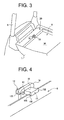
Fig. 3 is a fragmentary perspective view of the forklift ofFig. 1 with a hood removed; -
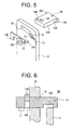
Fig. 4 is a perspective view of the battery-fixing device; -
Fig. 5 is an exploded perspective view of the battery-fixing device ofFig. 4 ; -
Fig. 6 is a sectional view of the battery-fixing device ofFig. 4 with a battery case locked; and -
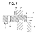
Fig. 7 is a sectional view of the battery-fixing device ofFig. 4 with the battery case unlocked. - The following will describe the embodiment of the battery-fixing device according to the present invention with reference to the accompanying drawings.
- It is noted that the left-hand side and the right-hand side as viewed in
Fig. 1 are the front side and the rear side of the forklift, respectively, and that the upper and lower sides as viewed inFig. 1 are the upper and lower sides of the forklift, respectively. - Referring to
Fig. 1 , the forklift has abody 1, a pair of drive wheels 2 (only one is shown) provided on opposite sides of the front portion of thebody 1, and a steer wheel 3 with two tires provided in the middle of the rear portion of thebody 1. Thebody 1 supports amast assembly 4 on the front portion thereof and anoperator seat 5 on the top portion thereof. The forklift further has a steering wheel 6 in front of theoperator seat 5, front andrear pillars operator seat 5, and abattery case 9 carrying abattery 9A under theoperator seat 5 and normally covered by a hood not shown (seeFigs. 2 and3 ). - Referring to
Figs. 3 through 5 , thebody 1 has aframe member 1A that extends vertically behind theoperator seat 5. Theframe member 1A is formed with a rectangular throughhole 1 B into which astopper 10 is inserted. Thebattery case 9 carrying thebattery 9A is placed in abattery space 20 that is formed in thebody 1. Theframe member 1A forms a part of thebattery space 20. - The
stopper 10 is in the form of a generally rectangular plate and movable in thethrough hole 1B of theframe member 1A. Thestopper 10 includes arectangular base 10A and a pair offlanges base 10A. Thebase 10A is slidingly movable in the throughhole 1B, but theflanges hole 1B. Thebase 10A has a laterally extendinggroove 10D formed on the lower surface thereof. Thegroove 10D is located on the front side of thebase 10A near thebattery case 9. Thebase 10A has arectangular lock hole 10E (a lock portion) and abolt hole 10F formed therethrough. Thelock hole 10E is located on the rear side of thebase 10A away from thebattery case 9. Thebolt hole 10F is located near thelock hole 10E. Thestopper 10 has abolt 11 that is screwed into thebolt hole 10F of thebase 10A from below (seeFigs. 6 and7 ). Thelock hole 10E may be replaced with a groove. - Referring to
Figs. 4 and5 , theframe member 1A has a fixedpin 1C that projects horizontally therefrom. Thepin 1C supports a generally L-shaped lock arm 12 on the side of theframe member 1A opposite to the battery case 9 (battery space 20). Thelock arm 12 is formed with ahole 12A that is associated with thepin 1C. With thepin 1C inserted in thehole 12A, aretaining pin 13 is inserted in ahole 1D of thepin 1C, so that thelock arm 12 is pivotally supported around thehole 12A relative to theframe member 1A. Thelock arm 12 is rotatable on theframe member 1A in a perpendicular direction to the movement of thestopper 10 in the throughhole 1B of theframe member 1A. Thelock arm 12 is formed with anengaging portion 12B and apush portion 12C. Theengaging portion 12B has a rectangular cross section and is located at one end of thelock arm 12 away from thepin 1C. Thepush portion 12C is located at the other end of thelock arm 12 near thepin 1C. - In the present embodiment, the battery-fixing device is composed of the above-described components such as the
frame member 1A, thestopper 10, thelock arm 12 and thebolt 11. - In operation of the battery-fixing device, as shown in
Fig. 6 , firstly, thestopper 10 is moved to a position where thegroove 10D can engage with thebattery case 9, so as to project from the throughhole 1 B of theframe member 1A toward thebattery case 9. Then thelock arm 12 is rotated so that theengaging portion 12B is fitted into thelock hole 10E of thestopper 10. By doing so, thestopper 10 is locked relative to the throughhole 1 B of theframe member 1A and prevented from dropping into thebattery space 20. This reliably prevents thebattery case 9 and thebattery 9A from being removed from thebattery space 20. - When the
lock arm 12 is rotated in opposite direction by pushing thepush portion 12C, the engagingportion 12B of thelock arm 12 is disengaged from thelock hole 10E of thestopper 10. In this condition, forward movement of thestopper 10 toward thebattery case 9 is restricted because thebolt 11 screwed into thestopper 10 interferes with theframe member 1A, which prevents thestopper 10 from being removed from the throughhole 1 B of theframe member 1A. - In replacement of the
battery 9A, as shown inFig.7 , thelock arm 12 is rotated so that the engagingportion 12B is disengaged from thelock hole 10E of thestopper 10. Then thestopper 10 is pulled back into the throughhole 1B from thebattery space 20 so that thegroove 10D is not engaged with thebattery case 9, which allows thebattery case 9 andbattery 9A to be removed from thebattery space 20 in thebody 1. - When the engaging
portion 12B of thelock arm 12 is disengaged from thelock hole 10E of thestopper 10, backward movement of thestopper 10 away from thebattery case 9 is restricted because theflanges stopper 10 interfere with theframe member 1A. As a result, thestopper 10 is prevented from being removed from the throughhole 1 B of theframe member 1A. - As described above, the engagement of the
lock arm 12 with thelock hole 10E of thestopper 10 keeps thestopper 10 projecting from the throughhole 1B of theframe member 1A toward thebattery space 20 so that thegroove 10D of thestopper 10 is engagable with thebattery case 9. The disengagement of thelock arm 12 from thelock hole 10E allows thestopper 10 to be pulled back into the throughhole 1 B so that thegroove 10D is not engaged with thebattery case 9. Thus, the battery-fixing device according to the invention reliably and simply prevents thebattery case 9 and thebattery 9A from being removed from thebattery space 20. Further, thestopper 10 has projections such as theflanges bolt 11 that interfere with theframe member 1A to restrict the movement of thestopper 10 when thelock arm 12 is disengaged from thelock hole 10E of thestopper 10. Therefore, thestopper 10 is prevented from being removed from the throughhole 1 B of theframe member 1A, and thestopper 10 can be used successively after replacement of thebattery 9A. That is, thesame stopper 10 can be used to prevent anotherbattery 9A provided subsequently from being removed from thebattery space 20. - Further, the battery-fixing device, the major component of which is the
frame member 1A located behind theoperator seat 5, does not become an obstacle to a forklift operator. - A battery-fixing device includes a frame member, a stopper and a lock arm. The frame member is formed in a body of the forklift and provided by a battery space where a battery case is placed. The frame member has a through hole. The stopper has a lock portion and a groove. The stopper is movable in the through hole. The lock arm is pivotally supported on the frame member so as to engage with or disengage from the lock portion. The engagement of the lock arm with the lock portion keeps the stopper projecting from the through hole toward the battery space so that the groove is engagable with the battery case. The disengagement of the lock arm from the lock portion allows the stopper to be pulled back into the through hole so that the groove is not engaged with the battery case.
Claims (7)
- A battery-fixing device for a battery forklift, the forklift having a battery case (9) in a battery space (20) that is formed in a body (1) of the forklift,
the battery-fixing device characterized by:a frame member (1A) formed in the body (1) and provided by the battery space (20), the frame member (1A) having a through hole (1 B);a stopper (10) having a lock portion (10E) and a groove (10D), the stopper (10) being movable in the through hole (1B); anda lock arm (12) pivotally supported on the frame member (1A) so as to engage with or disengage from the lock portion (10E),wherein the engagement of the lock arm (12) with the lock portion (10E) keeps the stopper (10) projecting from the through hole (1 B) toward the battery space (20) so that the groove (10D) is engagable with the battery case (9), and the disengagement of the lock arm (12) from the lock portion (10E) allows the stopper (10) to be pulled back into the through hole (1B) so that the groove (10D) is not engaged with the battery case (9). - The battery-fixing device according to claim 1, wherein the frame member (1A) extends vertically to form the battery space (20).
- The battery-fixing device according to claim 1, wherein the lock arm (12) is rotatable on the frame member (1A) in a perpendicular direction to the stopper movement in the through hole (1 B).
- The battery-fixing device according to claim 1, wherein the lock arm (12) is supported on the side of the frame member (1A) opposite to the battery space (20).
- The battery-fixing device according to claim 4, wherein the lock portion is provided by a rectangular hole (10E) that is formed through the stopper (10), and the lock arm (12) has an engaging portion (12B) that is fitted into the rectangular hole (10E) to lock the stopper (10).
- The battery-fixing device according to claim 1, wherein the stopper (10) is prevented from being removed from the through hole (1 B).
- The battery-fixing device according to claim 6, wherein the stopper (10) has a projection (10B, 10C, 11) that interferes with the frame member (1A) to restrict the movement of the stopper (10) when the lock arm (12) is disengaged from the lock portion (10E).
Applications Claiming Priority (1)
| Application Number | Priority Date | Filing Date | Title |
|---|---|---|---|
| JP2008326702A JP4803248B2 (en) | 2008-12-23 | 2008-12-23 | Battery fixing device for battery forklift |
Publications (2)
| Publication Number | Publication Date |
|---|---|
| EP2208702A1 true EP2208702A1 (en) | 2010-07-21 |
| EP2208702B1 EP2208702B1 (en) | 2013-10-02 |
Family
ID=42077671
Family Applications (1)
| Application Number | Title | Priority Date | Filing Date |
|---|---|---|---|
| EP09178532.9A Not-in-force EP2208702B1 (en) | 2008-12-23 | 2009-12-09 | Battery-fixing device for a battery forklift |
Country Status (4)
| Country | Link |
|---|---|
| US (1) | US8033352B2 (en) |
| EP (1) | EP2208702B1 (en) |
| JP (1) | JP4803248B2 (en) |
| CN (1) | CN101758767B (en) |
Families Citing this family (3)
| Publication number | Priority date | Publication date | Assignee | Title |
|---|---|---|---|---|
| DE102011018506A1 (en) * | 2011-04-23 | 2012-10-25 | Jungheinrich Aktiengesellschaft | Reach truck |
| US11183726B2 (en) * | 2017-12-15 | 2021-11-23 | Tiveni Mergeco, Inc. | Clamping bar holder component for a battery module and method thereof |
| CN111376787B (en) * | 2018-12-30 | 2021-08-13 | 浙江吉智新能源汽车科技有限公司 | battery replacement assembly for vehicles |
Citations (6)
| Publication number | Priority date | Publication date | Assignee | Title |
|---|---|---|---|---|
| JPS611458U (en) * | 1984-06-11 | 1986-01-07 | マツダ株式会社 | Automotive battery support device |
| JPS6281362U (en) * | 1985-11-09 | 1987-05-25 | ||
| JPS62139813U (en) * | 1986-02-28 | 1987-09-03 | ||
| JPH0594018U (en) * | 1992-05-25 | 1993-12-21 | 神鋼電機株式会社 | Battery retention device for vehicle |
| JP2001039692A (en) * | 1999-08-04 | 2001-02-13 | Toyota Autom Loom Works Ltd | Battery stopper device |
| JP2001055049A (en) * | 1999-08-19 | 2001-02-27 | Toyota Autom Loom Works Ltd | Battery stopper device and industrial vehicle equipped with the battery stopper device |
Family Cites Families (9)
| Publication number | Priority date | Publication date | Assignee | Title |
|---|---|---|---|---|
| JPS58211918A (en) | 1982-06-04 | 1983-12-09 | Nissan Motor Co Ltd | Battery case fixing device for industrial vehicle |
| JPS611458A (en) | 1984-06-12 | 1986-01-07 | Sumitomo Metal Ind Ltd | Continuous casting method of different kinds of metal |
| DE3534731A1 (en) | 1985-09-28 | 1987-04-09 | Bayer Ag | METHOD FOR PRODUCING HYDROXYBENZALDOXIM-O-ETHERS |
| JPS62139813A (en) | 1985-12-13 | 1987-06-23 | Sumitomo Metal Ind Ltd | Method for straight forward rolling of hot steel slab |
| JPS62153292U (en) * | 1986-03-20 | 1987-09-29 | ||
| JPH01141159U (en) | 1988-03-24 | 1989-09-27 | ||
| JP2527626Y2 (en) | 1990-11-15 | 1997-03-05 | 日本輸送機株式会社 | Battery jump-out prevention device |
| JPH0594018A (en) | 1991-10-02 | 1993-04-16 | Japan Synthetic Rubber Co Ltd | Radiation-sensitive composition |
| JP3613014B2 (en) * | 1998-07-24 | 2005-01-26 | 株式会社豊田自動織機 | Mechanism for holding a battery mounted on an industrial vehicle |
-
2008
- 2008-12-23 JP JP2008326702A patent/JP4803248B2/en not_active Expired - Fee Related
-
2009
- 2009-12-09 EP EP09178532.9A patent/EP2208702B1/en not_active Not-in-force
- 2009-12-10 US US12/634,917 patent/US8033352B2/en not_active Expired - Fee Related
- 2009-12-22 CN CN2009102611032A patent/CN101758767B/en not_active Expired - Fee Related
Patent Citations (6)
| Publication number | Priority date | Publication date | Assignee | Title |
|---|---|---|---|---|
| JPS611458U (en) * | 1984-06-11 | 1986-01-07 | マツダ株式会社 | Automotive battery support device |
| JPS6281362U (en) * | 1985-11-09 | 1987-05-25 | ||
| JPS62139813U (en) * | 1986-02-28 | 1987-09-03 | ||
| JPH0594018U (en) * | 1992-05-25 | 1993-12-21 | 神鋼電機株式会社 | Battery retention device for vehicle |
| JP2001039692A (en) * | 1999-08-04 | 2001-02-13 | Toyota Autom Loom Works Ltd | Battery stopper device |
| JP2001055049A (en) * | 1999-08-19 | 2001-02-27 | Toyota Autom Loom Works Ltd | Battery stopper device and industrial vehicle equipped with the battery stopper device |
Also Published As
| Publication number | Publication date |
|---|---|
| JP2010149939A (en) | 2010-07-08 |
| EP2208702B1 (en) | 2013-10-02 |
| JP4803248B2 (en) | 2011-10-26 |
| US20100155164A1 (en) | 2010-06-24 |
| CN101758767B (en) | 2013-04-24 |
| CN101758767A (en) | 2010-06-30 |
| US8033352B2 (en) | 2011-10-11 |
Similar Documents
| Publication | Publication Date | Title |
|---|---|---|
| EP3739658B1 (en) | Battery pack for electric work vehicle | |
| EP1844975B1 (en) | Seat swiveling device of a vehicle | |
| US8931364B2 (en) | Steering device | |
| CN109094476B (en) | sensor bracket | |
| US11193252B2 (en) | Structure for detachable front loader, detachable front loader, and work vehicle | |
| JP4297020B2 (en) | Connecting device for battery replacement cart | |
| JP6602903B2 (en) | Connecting device and towing vehicle | |
| EP2208702B1 (en) | Battery-fixing device for a battery forklift | |
| JP5407652B2 (en) | Vehicle door handle device | |
| EP3556719B1 (en) | Forklift side door | |
| US10259350B2 (en) | Lock release mechanism | |
| JP6943532B2 (en) | How to attach / detach the battery for battery-powered forklifts and battery-powered forklifts | |
| JP4367306B2 (en) | Battery replacement cart | |
| JP2012201130A (en) | Vehicle body structure of semi-trailer | |
| JP5702189B2 (en) | Cab lock safety device | |
| JP2019077390A (en) | Component conveyance truck | |
| JP4289567B2 (en) | Locking device mounted on a car or the like in a picking vehicle | |
| CN110030252B (en) | Fastening structure for vehicle body member and gasket for mounting vehicle body member | |
| US11999428B2 (en) | Side case attachment structure | |
| JP3976204B2 (en) | Wing lock device | |
| CN221137406U (en) | Small-sized carrier, locking mechanism of universal wheel of small-sized carrier and wheel assembly | |
| JP4163194B2 (en) | Car platform | |
| CN214451458U (en) | Auxiliary tool for mounting brake hard pipe | |
| JP3898204B2 (en) | Work machine mounting structure | |
| JP2026014321A (en) | Cover mounting structure for industrial vehicles |
Legal Events
| Date | Code | Title | Description |
|---|---|---|---|
| PUAI | Public reference made under article 153(3) epc to a published international application that has entered the european phase |
Free format text: ORIGINAL CODE: 0009012 |
|
| 17P | Request for examination filed |
Effective date: 20091209 |
|
| AK | Designated contracting states |
Kind code of ref document: A1 Designated state(s): AT BE BG CH CY CZ DE DK EE ES FI FR GB GR HR HU IE IS IT LI LT LU LV MC MK MT NL NO PL PT RO SE SI SK SM TR |
|
| GRAP | Despatch of communication of intention to grant a patent |
Free format text: ORIGINAL CODE: EPIDOSNIGR1 |
|
| INTG | Intention to grant announced |
Effective date: 20130422 |
|
| RIN1 | Information on inventor provided before grant (corrected) |
Inventor name: SHINODA, MASANORI |
|
| GRAS | Grant fee paid |
Free format text: ORIGINAL CODE: EPIDOSNIGR3 |
|
| GRAA | (expected) grant |
Free format text: ORIGINAL CODE: 0009210 |
|
| AK | Designated contracting states |
Kind code of ref document: B1 Designated state(s): AT BE BG CH CY CZ DE DK EE ES FI FR GB GR HR HU IE IS IT LI LT LU LV MC MK MT NL NO PL PT RO SE SI SK SM TR |
|
| REG | Reference to a national code |
Ref country code: GB Ref legal event code: FG4D |
|
| REG | Reference to a national code |
Ref country code: AT Ref legal event code: REF Ref document number: 634501 Country of ref document: AT Kind code of ref document: T Effective date: 20131015 Ref country code: CH Ref legal event code: EP |
|
| REG | Reference to a national code |
Ref country code: IE Ref legal event code: FG4D |
|
| REG | Reference to a national code |
Ref country code: DE Ref legal event code: R096 Ref document number: 602009019149 Country of ref document: DE Effective date: 20131128 |
|
| PGFP | Annual fee paid to national office [announced via postgrant information from national office to epo] |
Ref country code: DE Payment date: 20131219 Year of fee payment: 5 |
|
| REG | Reference to a national code |
Ref country code: AT Ref legal event code: MK05 Ref document number: 634501 Country of ref document: AT Kind code of ref document: T Effective date: 20131002 |
|
| REG | Reference to a national code |
Ref country code: NL Ref legal event code: VDEP Effective date: 20131002 |
|
| PG25 | Lapsed in a contracting state [announced via postgrant information from national office to epo] |
Ref country code: SI Free format text: LAPSE BECAUSE OF FAILURE TO SUBMIT A TRANSLATION OF THE DESCRIPTION OR TO PAY THE FEE WITHIN THE PRESCRIBED TIME-LIMIT Effective date: 20131002 |
|
| PGFP | Annual fee paid to national office [announced via postgrant information from national office to epo] |
Ref country code: IT Payment date: 20131217 Year of fee payment: 5 |
|
| REG | Reference to a national code |
Ref country code: LT Ref legal event code: MG4D |
|
| PG25 | Lapsed in a contracting state [announced via postgrant information from national office to epo] |
Ref country code: IS Free format text: LAPSE BECAUSE OF FAILURE TO SUBMIT A TRANSLATION OF THE DESCRIPTION OR TO PAY THE FEE WITHIN THE PRESCRIBED TIME-LIMIT Effective date: 20140202 Ref country code: CZ Free format text: LAPSE BECAUSE OF FAILURE TO SUBMIT A TRANSLATION OF THE DESCRIPTION OR TO PAY THE FEE WITHIN THE PRESCRIBED TIME-LIMIT Effective date: 20131002 Ref country code: NL Free format text: LAPSE BECAUSE OF FAILURE TO SUBMIT A TRANSLATION OF THE DESCRIPTION OR TO PAY THE FEE WITHIN THE PRESCRIBED TIME-LIMIT Effective date: 20131002 Ref country code: NO Free format text: LAPSE BECAUSE OF FAILURE TO SUBMIT A TRANSLATION OF THE DESCRIPTION OR TO PAY THE FEE WITHIN THE PRESCRIBED TIME-LIMIT Effective date: 20140102 Ref country code: SE Free format text: LAPSE BECAUSE OF FAILURE TO SUBMIT A TRANSLATION OF THE DESCRIPTION OR TO PAY THE FEE WITHIN THE PRESCRIBED TIME-LIMIT Effective date: 20131002 Ref country code: LT Free format text: LAPSE BECAUSE OF FAILURE TO SUBMIT A TRANSLATION OF THE DESCRIPTION OR TO PAY THE FEE WITHIN THE PRESCRIBED TIME-LIMIT Effective date: 20131002 Ref country code: FI Free format text: LAPSE BECAUSE OF FAILURE TO SUBMIT A TRANSLATION OF THE DESCRIPTION OR TO PAY THE FEE WITHIN THE PRESCRIBED TIME-LIMIT Effective date: 20131002 Ref country code: HR Free format text: LAPSE BECAUSE OF FAILURE TO SUBMIT A TRANSLATION OF THE DESCRIPTION OR TO PAY THE FEE WITHIN THE PRESCRIBED TIME-LIMIT Effective date: 20131002 Ref country code: BE Free format text: LAPSE BECAUSE OF FAILURE TO SUBMIT A TRANSLATION OF THE DESCRIPTION OR TO PAY THE FEE WITHIN THE PRESCRIBED TIME-LIMIT Effective date: 20131002 |
|
| PG25 | Lapsed in a contracting state [announced via postgrant information from national office to epo] |
Ref country code: CY Free format text: LAPSE BECAUSE OF FAILURE TO SUBMIT A TRANSLATION OF THE DESCRIPTION OR TO PAY THE FEE WITHIN THE PRESCRIBED TIME-LIMIT Effective date: 20131002 Ref country code: LV Free format text: LAPSE BECAUSE OF FAILURE TO SUBMIT A TRANSLATION OF THE DESCRIPTION OR TO PAY THE FEE WITHIN THE PRESCRIBED TIME-LIMIT Effective date: 20131002 Ref country code: ES Free format text: LAPSE BECAUSE OF FAILURE TO SUBMIT A TRANSLATION OF THE DESCRIPTION OR TO PAY THE FEE WITHIN THE PRESCRIBED TIME-LIMIT Effective date: 20131002 Ref country code: AT Free format text: LAPSE BECAUSE OF FAILURE TO SUBMIT A TRANSLATION OF THE DESCRIPTION OR TO PAY THE FEE WITHIN THE PRESCRIBED TIME-LIMIT Effective date: 20131002 Ref country code: PL Free format text: LAPSE BECAUSE OF FAILURE TO SUBMIT A TRANSLATION OF THE DESCRIPTION OR TO PAY THE FEE WITHIN THE PRESCRIBED TIME-LIMIT Effective date: 20131002 |
|
| PG25 | Lapsed in a contracting state [announced via postgrant information from national office to epo] |
Ref country code: PT Free format text: LAPSE BECAUSE OF FAILURE TO SUBMIT A TRANSLATION OF THE DESCRIPTION OR TO PAY THE FEE WITHIN THE PRESCRIBED TIME-LIMIT Effective date: 20140203 |
|
| REG | Reference to a national code |
Ref country code: DE Ref legal event code: R097 Ref document number: 602009019149 Country of ref document: DE |
|
| PG25 | Lapsed in a contracting state [announced via postgrant information from national office to epo] |
Ref country code: EE Free format text: LAPSE BECAUSE OF FAILURE TO SUBMIT A TRANSLATION OF THE DESCRIPTION OR TO PAY THE FEE WITHIN THE PRESCRIBED TIME-LIMIT Effective date: 20131002 |
|
| REG | Reference to a national code |
Ref country code: CH Ref legal event code: PL |
|
| PLBE | No opposition filed within time limit |
Free format text: ORIGINAL CODE: 0009261 |
|
| STAA | Information on the status of an ep patent application or granted ep patent |
Free format text: STATUS: NO OPPOSITION FILED WITHIN TIME LIMIT |
|
| PG25 | Lapsed in a contracting state [announced via postgrant information from national office to epo] |
Ref country code: MC Free format text: LAPSE BECAUSE OF FAILURE TO SUBMIT A TRANSLATION OF THE DESCRIPTION OR TO PAY THE FEE WITHIN THE PRESCRIBED TIME-LIMIT Effective date: 20131002 Ref country code: RO Free format text: LAPSE BECAUSE OF FAILURE TO SUBMIT A TRANSLATION OF THE DESCRIPTION OR TO PAY THE FEE WITHIN THE PRESCRIBED TIME-LIMIT Effective date: 20131002 Ref country code: LU Free format text: LAPSE BECAUSE OF FAILURE TO SUBMIT A TRANSLATION OF THE DESCRIPTION OR TO PAY THE FEE WITHIN THE PRESCRIBED TIME-LIMIT Effective date: 20131209 Ref country code: SK Free format text: LAPSE BECAUSE OF FAILURE TO SUBMIT A TRANSLATION OF THE DESCRIPTION OR TO PAY THE FEE WITHIN THE PRESCRIBED TIME-LIMIT Effective date: 20131002 |
|
| 26N | No opposition filed |
Effective date: 20140703 |
|
| GBPC | Gb: european patent ceased through non-payment of renewal fee |
Effective date: 20140102 |
|
| REG | Reference to a national code |
Ref country code: IE Ref legal event code: MM4A |
|
| REG | Reference to a national code |
Ref country code: FR Ref legal event code: ST Effective date: 20140829 |
|
| PG25 | Lapsed in a contracting state [announced via postgrant information from national office to epo] |
Ref country code: DK Free format text: LAPSE BECAUSE OF FAILURE TO SUBMIT A TRANSLATION OF THE DESCRIPTION OR TO PAY THE FEE WITHIN THE PRESCRIBED TIME-LIMIT Effective date: 20131002 |
|
| REG | Reference to a national code |
Ref country code: DE Ref legal event code: R097 Ref document number: 602009019149 Country of ref document: DE Effective date: 20140703 |
|
| PG25 | Lapsed in a contracting state [announced via postgrant information from national office to epo] |
Ref country code: CH Free format text: LAPSE BECAUSE OF NON-PAYMENT OF DUE FEES Effective date: 20131231 Ref country code: IE Free format text: LAPSE BECAUSE OF NON-PAYMENT OF DUE FEES Effective date: 20131209 Ref country code: LI Free format text: LAPSE BECAUSE OF NON-PAYMENT OF DUE FEES Effective date: 20131231 |
|
| PG25 | Lapsed in a contracting state [announced via postgrant information from national office to epo] |
Ref country code: FR Free format text: LAPSE BECAUSE OF NON-PAYMENT OF DUE FEES Effective date: 20131231 Ref country code: GB Free format text: LAPSE BECAUSE OF NON-PAYMENT OF DUE FEES Effective date: 20140102 |
|
| PG25 | Lapsed in a contracting state [announced via postgrant information from national office to epo] |
Ref country code: SM Free format text: LAPSE BECAUSE OF FAILURE TO SUBMIT A TRANSLATION OF THE DESCRIPTION OR TO PAY THE FEE WITHIN THE PRESCRIBED TIME-LIMIT Effective date: 20131002 |
|
| PG25 | Lapsed in a contracting state [announced via postgrant information from national office to epo] |
Ref country code: TR Free format text: LAPSE BECAUSE OF FAILURE TO SUBMIT A TRANSLATION OF THE DESCRIPTION OR TO PAY THE FEE WITHIN THE PRESCRIBED TIME-LIMIT Effective date: 20131002 |
|
| REG | Reference to a national code |
Ref country code: DE Ref legal event code: R119 Ref document number: 602009019149 Country of ref document: DE |
|
| PG25 | Lapsed in a contracting state [announced via postgrant information from national office to epo] |
Ref country code: HU Free format text: LAPSE BECAUSE OF FAILURE TO SUBMIT A TRANSLATION OF THE DESCRIPTION OR TO PAY THE FEE WITHIN THE PRESCRIBED TIME-LIMIT; INVALID AB INITIO Effective date: 20091209 Ref country code: BG Free format text: LAPSE BECAUSE OF FAILURE TO SUBMIT A TRANSLATION OF THE DESCRIPTION OR TO PAY THE FEE WITHIN THE PRESCRIBED TIME-LIMIT Effective date: 20131002 Ref country code: MK Free format text: LAPSE BECAUSE OF FAILURE TO SUBMIT A TRANSLATION OF THE DESCRIPTION OR TO PAY THE FEE WITHIN THE PRESCRIBED TIME-LIMIT Effective date: 20131002 |
|
| PG25 | Lapsed in a contracting state [announced via postgrant information from national office to epo] |
Ref country code: MT Free format text: LAPSE BECAUSE OF FAILURE TO SUBMIT A TRANSLATION OF THE DESCRIPTION OR TO PAY THE FEE WITHIN THE PRESCRIBED TIME-LIMIT Effective date: 20131002 Ref country code: GR Free format text: LAPSE BECAUSE OF NON-PAYMENT OF DUE FEES Effective date: 20131002 |
|
| PG25 | Lapsed in a contracting state [announced via postgrant information from national office to epo] |
Ref country code: DE Free format text: LAPSE BECAUSE OF NON-PAYMENT OF DUE FEES Effective date: 20150701 |
|
| PG25 | Lapsed in a contracting state [announced via postgrant information from national office to epo] |
Ref country code: IT Free format text: LAPSE BECAUSE OF NON-PAYMENT OF DUE FEES Effective date: 20141209 |
|
| PG25 | Lapsed in a contracting state [announced via postgrant information from national office to epo] |
Ref country code: NO Free format text: LAPSE BECAUSE OF FAILURE TO SUBMIT A TRANSLATION OF THE DESCRIPTION OR TO PAY THE FEE WITHIN THE PRESCRIBED TIME-LIMIT Effective date: 20140101 |
|
| PG25 | Lapsed in a contracting state [announced via postgrant information from national office to epo] |
Ref country code: GR Free format text: LAPSE BECAUSE OF FAILURE TO SUBMIT A TRANSLATION OF THE DESCRIPTION OR TO PAY THE FEE WITHIN THE PRESCRIBED TIME-LIMIT Effective date: 20140103 |