EP2208635B1 - Siège pour véhicule équipé d'un harnais - Google Patents
Siège pour véhicule équipé d'un harnais Download PDFInfo
- Publication number
- EP2208635B1 EP2208635B1 EP10290013A EP10290013A EP2208635B1 EP 2208635 B1 EP2208635 B1 EP 2208635B1 EP 10290013 A EP10290013 A EP 10290013A EP 10290013 A EP10290013 A EP 10290013A EP 2208635 B1 EP2208635 B1 EP 2208635B1
- Authority
- EP
- European Patent Office
- Prior art keywords
- backrest
- vehicle
- straps
- fixed
- fact
- Prior art date
- Legal status (The legal status is an assumption and is not a legal conclusion. Google has not performed a legal analysis and makes no representation as to the accuracy of the status listed.)
- Active
Links
Images

Classifications
-
- F—MECHANICAL ENGINEERING; LIGHTING; HEATING; WEAPONS; BLASTING
- F41—WEAPONS
- F41H—ARMOUR; ARMOURED TURRETS; ARMOURED OR ARMED VEHICLES; MEANS OF ATTACK OR DEFENCE, e.g. CAMOUFLAGE, IN GENERAL
- F41H7/00—Armoured or armed vehicles
- F41H7/02—Land vehicles with enclosing armour, e.g. tanks
- F41H7/04—Armour construction
- F41H7/046—Shock resilient mounted seats for armoured or fighting vehicles
-
- B—PERFORMING OPERATIONS; TRANSPORTING
- B60—VEHICLES IN GENERAL
- B60N—SEATS SPECIALLY ADAPTED FOR VEHICLES; VEHICLE PASSENGER ACCOMMODATION NOT OTHERWISE PROVIDED FOR
- B60N2/00—Seats specially adapted for vehicles; Arrangement or mounting of seats in vehicles
- B60N2/24—Seats specially adapted for vehicles; Arrangement or mounting of seats in vehicles for particular purposes or particular vehicles
-
- B—PERFORMING OPERATIONS; TRANSPORTING
- B60—VEHICLES IN GENERAL
- B60R—VEHICLES, VEHICLE FITTINGS, OR VEHICLE PARTS, NOT OTHERWISE PROVIDED FOR
- B60R22/00—Safety belts or body harnesses in vehicles
- B60R22/18—Anchoring devices
- B60R22/22—Anchoring devices secured to the vehicle floor
-
- B—PERFORMING OPERATIONS; TRANSPORTING
- B60—VEHICLES IN GENERAL
- B60R—VEHICLES, VEHICLE FITTINGS, OR VEHICLE PARTS, NOT OTHERWISE PROVIDED FOR
- B60R22/00—Safety belts or body harnesses in vehicles
- B60R22/18—Anchoring devices
- B60R22/24—Anchoring devices secured to the side, door, or roof of the vehicle
-
- B—PERFORMING OPERATIONS; TRANSPORTING
- B60—VEHICLES IN GENERAL
- B60R—VEHICLES, VEHICLE FITTINGS, OR VEHICLE PARTS, NOT OTHERWISE PROVIDED FOR
- B60R22/00—Safety belts or body harnesses in vehicles
- B60R22/02—Semi-passive restraint systems, e.g. systems applied or removed automatically but not both ; Manual restraint systems
- B60R2022/027—Four-point seat belt systems, e.g. with the two upper points connected together
-
- B—PERFORMING OPERATIONS; TRANSPORTING
- B60—VEHICLES IN GENERAL
- B60R—VEHICLES, VEHICLE FITTINGS, OR VEHICLE PARTS, NOT OTHERWISE PROVIDED FOR
- B60R22/00—Safety belts or body harnesses in vehicles
- B60R22/18—Anchoring devices
- B60R2022/1818—Belt guides
-
- B—PERFORMING OPERATIONS; TRANSPORTING
- B60—VEHICLES IN GENERAL
- B60R—VEHICLES, VEHICLE FITTINGS, OR VEHICLE PARTS, NOT OTHERWISE PROVIDED FOR
- B60R22/00—Safety belts or body harnesses in vehicles
- B60R22/18—Anchoring devices
- B60R22/26—Anchoring devices secured to the seat
Definitions
- the technical field of the invention is that of vehicle seats and in particular seats for armored vehicles.
- Automotive seats most often have a seat belt that combines a ventral strap and an angled chest strap.
- the maintenance provided by such belts is satisfactory in the usual conditions of use.
- the harnesses generally comprise a substantially horizontal ventral strap and two shoulder straps that maintain the user in support against the seat back.
- armored vehicles and in particular troop transport vehicles must have seats that provide a secure base for several infantrymen but at the same time occupy a small volume in the passenger compartment.
- a seat for armored vehicle corresponding to the preamble of claim 1 which comprises a tubular nacelle suspended at a ceiling of the vehicle.
- the nacelle is articulated to allow the folding of the seat.
- a holding harness comprises two shoulder straps that cross the seat back and are fixed at a common attachment point secured to a lower part of the nacelle.
- Such a seat has disadvantages.
- the invention aims to provide a seat which provides an effective and ergonomic support of the user, and regardless of his size (between the limits of the 5th percentile female and 95th percentile male of the population).
- the seat according to the invention is light and removable structure but it nevertheless provides effective maintenance in case of longitudinal accelerations (parallel to the seat back).
- the subject of the invention is a vehicle seat incorporating a backrest integral with a structure of the vehicle and a harness comprising two shoulder straps and allowing the occupant of the seat to be supported against the backrest, the backrest comprising orifices allowing the passage of a first end of the harness straps which comprises a member intended to cooperate with a first attachment means, seat characterized in that each strap passes through a fixed loop, positioned behind the backrest and interposed between the latter and the first fixing means, the fixed passer being secured to the vehicle structure and positioned at a height so as to provide an orientation of the harness straps at an angle to the horizontal between 0 ° and 45 ° °.
- Fixed loops are advantageously secured to substantially vertical flexible bands fixed between a high attachment point and a low attachment point, these two points being integral with the vehicle structure.
- the flexible strips may comprise a portion of fixed length and a portion of adjustable length to ensure a tension of the band, the passer being disposed between the two parts of the band.
- the flexible strips may be fixed at the top attachment point by detachable connection means.
- each flexible band may be constituted by the first fastening means of the strap associated with said strip.
- the width of the strips will advantageously be greater than or equal to the width of the straps of the harness.
- the backrest of the seat may be a flexible backrest fixed between a seat integral with the structure and a profile also secured to the structure and disposed in the vicinity of a ceiling of the vehicle, the file being fixed to a detachable way at the level of the profile
- a seat 1 according to one embodiment of the invention comprises a backrest 2 and a seat 3.
- the seat 3 is integral with a wall 4 of the vehicle structure.
- the backrest 2 is a flexible backrest (for example canvas or synthetic material) which is fixed between the seat 3 and a profile 5 which is also secured to the vehicle structure.
- the section 5 is close to the ceiling 6 of the vehicle to which it is fixed by legs 7.
- the backrest 2 is fixed in a detachable manner at the section 5, for example by hooks 8. It is thus easy to detach the file 2 to allow access to the space behind the seat 1 and which serves as a storage area.
- the seat 1 also carries a harness 9 which comprises two shoulder straps 10a, 10b and a ventral strap 11.
- the ventral strap 11 is closed by a quick coupler 12.
- the shoulder straps 10a, 10b allow the occupant of the seat to be supported against the backrest 2. These shoulder straps are integral with one side of the ventral strap 11 and they each carry a first end which comprises a member 14a, 14b (here a tab) which is intended to cooperate with a first fastening means 17a, 17b (here a screw) ensuring the fastening of the tab 14a, 14b and the wall 4 of the vehicle structure.
- the shoulder straps 10a, 10b and the ventral strap 11 have adjustable lengths to allow the adaptation of the harness 9 to different occupant morphologies (not shown adjustment means).
- the flexible backrest 2 has two ports 15 which allow each passage of one of the straps 10a, 10b of the harness 9.
- the dimensions of these openings are large enough to allow an adaptation to the anthropometric differences between the 5th percentile female and the 95th male percentile.
- each strap 10a, 10b passes through a fixed loop 16a, 16b which is positioned behind the backrest 2 and which is thus interposed between the backrest 2 and the first fixing means.
- Each passer 16a, 16b is secured to a flexible band 18a, 18b which is substantially vertical.
- each flexible band is here constituted by the first attachment means 17a, 17b of the strap 10a, 10b associated with said strip 18a, 18b.
- the upper attachment point 19a, 19b is arranged on the section 5 which will comprise suitable holes for fixing a detachable quick link means, for example a carabiner 20a, 20b secured to the end of the strip 18a, 18b (see figure 2 ).
- a detachable quick link means for example a carabiner 20a, 20b secured to the end of the strip 18a, 18b (see figure 2 ).
- the flexible strips 18a, 18b are thus integral, on one side of the profile 5 adjacent to the ceiling 6, and on the other side of the wall 4.
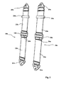
- each band 18a, 18b has a fixed length portion 22a, 22b which extends between the loop 16a, 16b and a lower leg 21a, 21b and a portion of adjustable length 23a, 23b disposed between the loop 16a, 16b and the upper carabiner 20a, 20b.
- the lower slot 26a, 26b of each passer 16a, 16b will have a width sufficient to pass both the fixed portion 22a, 22b of the band and the strap 10a, 10b of the harness.
- the adjustment of the length of the band is done using an adjuster 24a, 24b which ensures the locking of the adjustable portion 23a, 23b of the band to the desired length.
- the carabiner 20a, 20b on the section 5 can be stretched strips 18a, 18b.
- the adjustment makes it easy to take into account the dimensional dispersions at the level of the vehicle structure and in particular the variability in the distance between the top and bottom attachment points from one vehicle to another.
- hooks 8 attached to the flexible backrest 2 are also connected to the backrest 2 by adjustable length straps 25.
- each band 18a, 18b being of fixed length, the loop 16a, 16b is always positioned at the same level vertically with respect to the structure (wall 4). This passer 16a, 16b will be positioned in height to ensure orientation of the harness straps at an angle to the horizontal Hz between 0 ° and 45 °.
- passer 16a, 16b will be here substantially opposite the lower edge of each opening 15 of the folder 2.
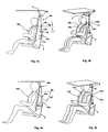
- FIGS 3a and 3b show someone the 5th percentile female using the seat according to the invention.
- the shoulder straps 10a, 10b are oriented substantially horizontally (the angle formed by the straps 10a, 10b with the horizontal Hz is approximately 1 °) .
- the straps 10a, 10b are then substantially in contact with the lower edge of the openings 15 of the backrest 2.
- FIGS. 4a and 4b show the same seat 2 used by a 95 th percentile male.
- the shoulder straps 10a, 10b form an angle with the horizontal Hz which is 45 °.
- the straps 10a, 10b are then close to the upper edge of the openings 15.
- the straps form with the horizontal an angle between 1 ° and 45 ° which is consistent with the ergonomic standards required for a firm and comfortable maintenance of the entire population .
- the invention ensures such a result while implementing a seat 1 of light structure with 2 flexible backrest. This is achieved thanks to the strips 18a, 18b which make it possible to transfer the mechanical and ergonomic stresses of the maintenance onto the structure of the vehicle itself (section 5 and plate 4) while allowing rapid disassembly of the strips 18a, 18b (with the carabiners 20a, 20b) to allow access to the space behind the folders 2.
- the loops 16a, 16b can ergonomically position the straps 10a, 10b relative to users despite fixing the straps at the bottom of the vehicle.
- the strips 18a, 18b will be given a width greater than that of the straps 10a, 10b. Such an arrangement makes it possible to further stiffen the device with respect to the twisting of the strips 18a, 18b. Thus passers 16a, 16b are also given a larger width which facilitates the passage of the straps 10a, 10b in the loops.
- the strips 18a, 18b will be given a width that is greater than or equal to the width of the straps 10a, 10b plus 20%.
- each fixed loop is not secured to a flexible band but is attached to a rigid vertical bar.
Landscapes
- Engineering & Computer Science (AREA)
- Mechanical Engineering (AREA)
- General Engineering & Computer Science (AREA)
- Aviation & Aerospace Engineering (AREA)
- Transportation (AREA)
- Seats For Vehicles (AREA)
- Chair Legs, Seat Parts, And Backrests (AREA)
- Passenger Equipment (AREA)
- Automotive Seat Belt Assembly (AREA)
Description
- Le domaine technique de l'invention est celui des sièges pour véhicules et en particulier des sièges pour véhicules blindés.
- Les sièges automobiles comportent le plus souvent une ceinture de sécurité qui associe une sangle ventrale et une sangle pectorale en biais. Le maintien assuré par de telles ceintures est satisfaisant dans les conditions d'emploi habituelles.
- Il est cependant classique aujourd'hui de munir un siège de véhicule de harnais permettant d'assurer un maintien plus ferme de l'occupant du siège. Les harnais comportent généralement une sangle ventrale sensiblement horizontale et deux sangles d'épaule qui assurent le maintien de l'usager en appui contre le dossier du siège.
- Un tel maintien des deux épaules est particulièrement important dans les véhicules automobiles rapides ou dans les véhicules militaires. En effet ces derniers subissent des chocs violents lors des phases de roulage en tout terrain, chocs ayant des directions variables. Il est donc nécessaire d'assurer un maintien ferme et symétrique du dos de l'usager.
- Par ailleurs les véhicules blindés et en particulier les véhicules de transport de troupes doivent comporter des sièges qui assurent une assise sécurisée à plusieurs fantassins mais qui en même temps occupent un volume réduit dans l'habitacle.
- De telles exigences sont plutôt contradictoires, la légèreté de l'assise semblant peu compatible avec la fermeté du maintien.
- On connaît par le brevet
US2005/0264082 un siège pour véhicule blindé correspondant au préambule de la revendication 1 qui comprend une nacelle tubulaire suspendue au niveau d'un plafond du véhicule. La nacelle est articulée pour permettre le repli du siège. Un harnais de maintien comprend deux sangles d'épaule qui traversent le dossier du siège et sont fixées au niveau d'un point d'attache commun solidaire d'une partie basse de la nacelle. - Un tel siège présente des inconvénients.
- Tout d'abord les deux sangles d'épaule du harnais ont un seul et même point de fixation au niveau de l'extrémité d'une sangle fixée à la nacelle. Il en résulte un risque de torsion de cette sangle commune ce qui réduit la rigidité du maintien notamment en cas d'accélérations parallèles au dossier. Or ces accélérations sont la règle dans les véhicules de transport de troupes pour lesquels les sièges sont le plus souvent fixés avec leurs dossiers parallèles au sens de la marche du véhicule.
- Ensuite les sangles d'épaule du harnais forment un angle avec l'horizontale voisin de 90°. Un tel type de maintien est insuffisamment ergonomique. Le confort et l'efficacité du maintien nécessitent en effet un angle de ces sangles avec l'horizontale qui est inférieur à 45°. Une telle condition est en particulier précisée par le règlement communautaire R16 sur l'installation des ceintures dans les véhicules (directive CE 77/541 du 28/06/1977 et notamment sa modification 96/36 du 17/07/1996).
- Enfin le siège proposé par
US2005/0264082 présente un encombrement encore trop important puisqu'il ne permet pas d'avoir un accès facile aux zones de l'habitacle situées derrière le dossier du siège. - L'invention a pour but de proposer un siège qui assure un maintien efficace et ergonomique de l'usager, et ce quelle que soit sa corpulence (comprise entre les limites des 5ème percentile féminin et 95ème percentiles masculin de la population).
- Le siège selon l'invention est de structure légère et démontable mais il assure cependant un maintien efficace en cas d'accélérations longitudinales (parallèles au dossier du siège).
- Ainsi l'invention a pour objet un siège pour véhicule incorporant un dossier solidaire d'une structure du véhicule et un harnais comportant deux sangles d'épaule et permettant le maintien de l'occupant du siège en appui contre le dossier, le dossier comportant des orifices permettant le passage d'une première extrémité des sangles du harnais qui comporte un organe destiné à coopérer avec un premier moyen de fixation, siège caractérisé en ce que chaque sangle traverse un passant fixe, positionné en arrière du dossier et interposé entre ce dernier et le premier moyen de fixation, le passant fixe étant solidaire de la structure du véhicule et positionné en hauteur de façon à assurer une orientation des sangles des harnais avec un angle par rapport à l'horizontale compris entre 0° et 45°.
- Les passants fixes seront avantageusement solidaires de bandes souples sensiblement verticales fixées entre un point d'attache haut et un point d'attache bas, ces deux points étant solidaires de la structure du véhicule.
- Les bandes souples pourront comporter une partie de longueur fixe et une partie de longueur réglable permettant d'assurer une tension de la bande, le passant étant disposé entre les deux parties de la bande.
- Les bandes souples pourront être fixées au niveau du point d'attache haut par un moyen de liaison détachable.
- Le point d'attache bas de chaque bande souple pourra être constitué par le premier moyen de fixation de la sangle associée à ladite bande.
- La largeur des bandes sera avantageusement supérieure ou égale à la largeur des sangles du harnais.
- Selon un mode particulier de réalisation, le dossier du siège pourra être un dossier souple fixé entre une assise solidaire de la structure et un profilé lui aussi solidaire de la structure et disposé au voisinage d'un plafond du véhicule, le dossier étant fixé d'une façon détachable au niveau du profilé
- L'invention sera mieux comprise à la lecture du descriptif qui va suivre d'un mode particulier de réalisation, description faite en référence aux dessins annexés et dans lesquels :
- la
figure 1 est une vue en perspective arrière d'un siège selon un mode de réalisation de l'invention, - la
figure 2 représente les bandes souples seules, - les
figures 3a et 3b sont deux vues d'une utilisation d'un siège selon l'invention par une personne du 5ème percentile féminin, lafigure 3a étant une vue latérale et lafigure 3b une vue en perspective de trois quarts avant, - les
figures 4a et 4b sont deux vues d'une utilisation d'un siège selon l'invention par une personne du 95ème percentile masculin, lafigure 4a étant une vue latérale et lafigure 4b une vue en perspective de trois quarts avant. - En se reportant à la
figure 1 , un siège 1 selon un mode de réalisation de l'invention comprend un dossier 2 et une assise 3. L'assise 3 est solidaire d'une paroi 4 de la structure du véhicule. Le dossier 2 est un dossier souple (par exemple en toile ou en matériau synthétique) qui est fixé entre l'assise 3 et un profilé 5 qui est lui aussi solidaire de la structure du véhicule. - Le profilé 5 est voisin du plafond 6 du véhicule auquel il est fixé par des pattes 7. Le dossier 2 est fixé d'une façon détachable au niveau du profilé 5, par exemple par des crochets 8. Il est ainsi aisé de détacher le dossier 2 pour permettre un accès à l'espace situé derrière le siège 1 et qui sert de zone de rangement.
- Le siège 1 porte aussi un harnais 9 qui comporte deux sangles d'épaule 10a, 10b et une sangle ventrale 11.
- La sangle ventrale 11 se ferme par une attache rapide 12.
- Les sangles d'épaule 10a, 10b permettent le maintien de l'occupant du siège en appui contre le dossier 2. Ces sangles d'épaule sont solidaires d'un côté de la sangle ventrale 11 et elles portent chacune une première extrémité qui comporte un organe 14a, 14b (ici une patte) qui est destiné à coopérer avec un premier moyen de fixation 17a, 17b (ici une vis) assurant la solidarisation de la patte 14a, 14b et de la paroi 4 de la structure du véhicule. D'une façon classique, les sangles d'épaule 10a, 10b et la sangle ventrale 11 ont des longueurs réglables pour permettre l'adaptation du harnais 9 à différentes morphologies d'occupants (moyens de réglage non représentés).
- Le dossier souple 2 comporte deux orifices 15 qui permettent chacun le passage d'une des sangles 10a, 10b du harnais 9. Les dimensions de ces orifices sont suffisamment grandes pour permettre une adaptation aux écarts anthropométriques entre le 5ème percentile féminin et le 95ème percentile masculin.
- Conformément à une caractéristique essentielle de l'invention, chaque sangle 10a, 10b traverse un passant fixe 16a,16b qui est positionné en arrière du dossier 2 et qui est ainsi interposé entre le dossier 2 et le premier moyen de fixation.
- Chaque passant 16a, 16b est solidaire d'une bande souple 18a, 18b qui est sensiblement verticale.
- Ces bandes 18a, 18b sont fixées entre un point d'attache haut 19a, 19b et un point d'attache bas solidaire de la paroi 4. Ces deux points sont solidaires de la structure du véhicule.
- Le point d'attache bas de chaque bande souple est ici constitué par le premier moyen de fixation 17a, 17b de la sangle 10a, 10b associée à ladite bande 18a, 18b.
- Le point d'attache haut 19a, 19b est disposé sur le profilé 5 qui comportera des trous appropriés permettant la fixation d'un moyen de liaison rapide détachable, par exemple un mousqueton 20a, 20b solidaire de l'extrémité de la bande 18a, 18b (voir
figure 2 ). - Les bandes souples 18a, 18b sont donc ainsi solidaires, d'un côté du profilé 5 voisin du plafond 6, et de l'autre de la paroi 4.
- La
figure 2 montre de façon plus précise les bandes souples 18a, 18b seules. On remarque que chaque bande 18a,18b comporte une partie de longueur fixe 22a, 22b qui s'étend entre le passant 16a, 16b et une patte inférieure 21a, 21b et une partie de longueur réglable 23a,23b disposée entre le passant 16a, 16b et le mousqueton supérieur 20a, 20b. La fente inférieure 26a, 26b de chaque passant 16a, 16b aura une largeur suffisante pour laisser passer à la fois la partie fixe 22a, 22b de la bande et la sangle 10a, 10b du harnais. - Le réglage de la longueur de la bande se fait à l'aide d'un ajusteur 24a, 24b qui assure le blocage de la partie réglable 23a, 23b de la bande à la longueur souhaitée.
- Après fixation du mousqueton 20a, 20b sur le profilé 5 on peut ainsi tendre les bandes 18a, 18b. Le réglage permet de prendre en compte facilement les dispersions de dimensions au niveau de la structure du véhicule et en particulier la variabilité de la distance entre les points d'attache haut et bas d'un véhicule à l'autre.
- On notera par ailleurs que les crochets 8 fixés au dossier souple 2 sont eux aussi reliés au dossier 2 par des sangles à longueurs réglables 25.
- La partie inférieure 21a, 21b de chaque bande 18a, 18b étant de longueur fixe, le passant 16a, 16b se trouve toujours positionné au même niveau verticalement par rapport à la structure (paroi 4). Ce passant 16a, 16b sera positionné en hauteur de façon à assurer une orientation des sangles des harnais avec un angle par rapport à l'horizontale Hz compris entre 0° et 45°.
- Concrètement le passant 16a, 16b se trouvera ici sensiblement en regard du bord inférieur de chaque ouverture 15 du dossier 2.
- Les
figures 3a et 3b montrent une personne du 5ème percentile féminin utilisant le siège selon l'invention. - On voit sur ces figures que, pour une petite morphologie d'usager, les sangles d'épaule 10a, 10b sont orientées sensiblement horizontalement (l'angle formé par les sangles 10a, 10b avec l'horizontale Hz est d'environ 1°).
- Les sangles 10a, 10b sont alors sensiblement en contact avec le bord inférieur des ouvertures 15 du dossier 2.
- Les
figures 4a et 4b montrent le même siège 2 utilisé par une personne du 95ème percentile masculin. Pour la morphologie d'usager la plus forte on voit donc que les sangles d'épaule 10a, 10b forment un angle avec l'horizontale Hz qui est de 45°. Les sangles 10a,10b sont alors proches du bord supérieur des ouvertures 15. - On voit donc qu'avec le siège selon l'invention, les sangles forment avec l'horizontale un angle compris entre 1° et 45° ce qui est conforme aux normes ergonomiques requises pour un maintien ferme et confortable de l'ensemble de la population. L'invention assure un tel résultat tout en mettant en oeuvre un siège 1 de structure légère au dossier 2 souple. Ceci est obtenu grâce aux bandes 18a, 18b qui permettent de transférer les contraintes mécaniques et ergonomiques du maintien sur la structure même du véhicule (profilé 5 et plaque 4) tout en permettant un démontage rapide des bandes 18a, 18b (grâce aux mousquetons 20a,20b) pour permettre un accès à l'espace derrière les dossiers 2.
- Les passants 16a, 16b permettent de positionner ergonomiquement les sangles 10a, 10b par rapport aux usagers malgré une fixation des sangles en partie basse du véhicule.
- Avantageusement on donnera aux bandes 18a, 18b une largeur supérieure à celle des sangles 10a, 10b. Une telle disposition permet de rigidifier encore plus le dispositif vis à vis de la torsion des bandes 18a, 18b. On donne ainsi également aux passants 16a, 16b une largeur plus importante ce qui facilite le passage des sangles 10a, 10b dans les passants. On donnera par exemple aux bandes 18a, 18b une largeur qui est supérieure ou égale à la largeur des sangles 10a, 10b plus 20%.
- A titre de variante on pourra définir un siège dans lequel chaque passant fixe n'est pas solidaire d'une bande souple mais est fixé à une barre verticale rigide. On choisira les dimensions des barres pour assurer la rigidité souhaitée pour le maintien des sangles. Une telle solution rend cependant plus difficile l'accès à l'espace de rangement en arrière du dossier.
Claims (7)
- Siège (1) pour véhicule incorporant un dossier (2) solidaire d'une structure (4, 5) du véhicule et un harnais (9) comportant deux sangles d'épaule (10a, 10b) et permettant le maintien de l'occupant du siège en appui contre le dossier (2), le dossier comportant des orifices (15) permettant le passage d'une première extrémité des sangles (10a, 10b) du harnais qui comporte un organe (14a,14b) destiné à coopérer avec un premier moyen de fixation (17a, 17b), siège caractérisé en ce que chaque sangle (10a, 10b) traverse un passant fixe (16a, 16b) positionné en arrière du dossier (2) et interposé entre ce dernier et le premier moyen de fixation, le passant fixe (16a, 16b) étant solidaire de la structure du véhicule et positionné en hauteur de façon à assurer une orientation des sangles (10a, 10b) des harnais avec un angle par rapport à l'horizontale compris entre 0° et 45°.
- Siège pour véhicule selon la revendication 1, caractérisé en ce que les passants fixes (16a, 16b) sont solidaires de bandes souples (18a, 18b) sensiblement verticales fixées entre un point d'attache haut (19a, 19b) et un point d'attache bas, ces deux points étant solidaires de la structure du véhicule.
- Siège pour véhicule selon la revendication 2, caractérisé en ce que les bandes souples (18a, 18b) comportent une partie (22a, 22b) de longueur fixe et une partie (23a, 23b) de longueur réglable permettant d'assurer une tension de la bande (18a, 18b), le passant (16a, 16b) étant disposé entre les deux parties de la bande.
- Siège pour véhicule selon une des revendications 2 ou 3, caractérisé en ce que les bandes souples (18a, 18b) sont fixées au niveau du point d'attache haut par un moyen de liaison détachable (20a, 20b).
- Siège pour véhicule selon la revendication 2 ou 3, caractérisé en ce que le point d'attache bas de chaque bande souple est constitué par le premier moyen de fixation (17a, 17b) de la sangle (10a, 10b) associée à ladite bande (18a, 18b).
- Siège pour véhicule selon une des revendications 2 à 5, caractérisé en ce que la largeur des bandes (18a, 18b) est supérieure ou égale à la largeur des sangles (10a, 10b) du harnais.
- Siège pour véhicule selon une des revendications 1 à 6, caractérisé en ce que le dossier (2) du siège est un dossier souple qui est fixé entre une assise (3) solidaire de la structure et un profilé (5) lui aussi solidaire de la structure et disposé au voisinage d'un plafond du véhicule, le dossier (2) étant fixé d'une façon détachable au niveau du profilé (5).
Applications Claiming Priority (1)
| Application Number | Priority Date | Filing Date | Title |
|---|---|---|---|
| FR0900225A FR2941196B1 (fr) | 2009-01-19 | 2009-01-19 | Siege pour vehicule equipe d'un harnais |
Publications (2)
| Publication Number | Publication Date |
|---|---|
| EP2208635A1 EP2208635A1 (fr) | 2010-07-21 |
| EP2208635B1 true EP2208635B1 (fr) | 2011-09-07 |
Family
ID=41100765
Family Applications (1)
| Application Number | Title | Priority Date | Filing Date |
|---|---|---|---|
| EP10290013A Active EP2208635B1 (fr) | 2009-01-19 | 2010-01-13 | Siège pour véhicule équipé d'un harnais |
Country Status (4)
| Country | Link |
|---|---|
| EP (1) | EP2208635B1 (fr) |
| AT (1) | ATE523380T1 (fr) |
| ES (1) | ES2372920T3 (fr) |
| FR (1) | FR2941196B1 (fr) |
Cited By (1)
| Publication number | Priority date | Publication date | Assignee | Title |
|---|---|---|---|---|
| EP2630940A1 (fr) | 2012-02-21 | 2013-08-28 | NEXTER Systems | Dispositif support de brancard et véhicule sanitaire équipé d'un tel dispositif |
Families Citing this family (4)
| Publication number | Priority date | Publication date | Assignee | Title |
|---|---|---|---|---|
| EP2371620A1 (fr) * | 2010-04-01 | 2011-10-05 | BAE Systems Safety Products Inc. | Siège unique |
| FR3022193B1 (fr) | 2014-06-12 | 2018-03-02 | Nexter Systems | Dispositif de depose/repöse rapide d'un dossier de siege de vehicule, et ensemble siege le comprenant |
| CN110697051B (zh) * | 2019-09-25 | 2021-05-04 | 湖北航宇嘉泰飞机设备有限公司 | 一种航空座椅肩带出口高度调节机构 |
| US11305678B2 (en) * | 2020-08-20 | 2022-04-19 | Aguti Produktentwicklung & Design Gmbh | Belt mount for a vehicle seat or a vehicle bench seat and vehicle seat arrangement |
Family Cites Families (5)
| Publication number | Priority date | Publication date | Assignee | Title |
|---|---|---|---|---|
| US6817673B2 (en) * | 2002-04-17 | 2004-11-16 | Lear Corporation | Vehicle seat assembly |
| AT500225B1 (de) * | 2004-05-06 | 2009-06-15 | Steyr Daimler Puch Ag | Sitz für ein gepanzertes fahrzeug |
| GB0511317D0 (en) * | 2005-06-03 | 2005-07-13 | Macliver Kevin S | Restraining |
| DE102007002371B3 (de) * | 2007-01-16 | 2008-05-21 | Autoflug Gmbh | Mit einem Schultergurtzeug versehener Sicherheitssitz ohne Seiteneinbauten |
| DE102007011962B3 (de) * | 2007-03-09 | 2008-02-07 | Autoflug Gmbh | An einem aus Federelementen bestehenden Stützgerüst festgelegter Sicherheitssitz |
-
2009
- 2009-01-19 FR FR0900225A patent/FR2941196B1/fr not_active Expired - Fee Related
-
2010
- 2010-01-13 EP EP10290013A patent/EP2208635B1/fr active Active
- 2010-01-13 AT AT10290013T patent/ATE523380T1/de not_active IP Right Cessation
- 2010-01-13 ES ES10290013T patent/ES2372920T3/es active Active
Cited By (1)
| Publication number | Priority date | Publication date | Assignee | Title |
|---|---|---|---|---|
| EP2630940A1 (fr) | 2012-02-21 | 2013-08-28 | NEXTER Systems | Dispositif support de brancard et véhicule sanitaire équipé d'un tel dispositif |
Also Published As
| Publication number | Publication date |
|---|---|
| ATE523380T1 (de) | 2011-09-15 |
| EP2208635A1 (fr) | 2010-07-21 |
| FR2941196A1 (fr) | 2010-07-23 |
| FR2941196B1 (fr) | 2011-01-14 |
| ES2372920T3 (es) | 2012-01-27 |
Similar Documents
| Publication | Publication Date | Title |
|---|---|---|
| EP2129551B1 (fr) | Dispositif de rangement de bagages pour véhicule de transport en commun | |
| EP2208635B1 (fr) | Siège pour véhicule équipé d'un harnais | |
| FR2782484A1 (fr) | Dispositif de siege arriere pour habitacles | |
| FR2996501A1 (fr) | Siege auto pour enfant, a assise reglable en hauteur | |
| EP3164296B1 (fr) | Equipement pour le transport d'un enfant dans un vehicule, comprenant une embase et une nacelle assemblables par translation, embase et nacelle correspondantes | |
| FR3045522A1 (fr) | Nacelle pour enfant presentant une armature interne a structure asymetrique | |
| EP2477841B1 (fr) | Siège de véhicule automobile comportant un élément d'assise apte à former un espace de rangement | |
| EP3186106B1 (fr) | Siège escamotable avec tablette pour véhicule et véhicule équipé de ce siège | |
| FR2992264A1 (fr) | Dispositif de fermeture pour la mise en oeuvre d'un espace de rangement sous un siege de vehicule | |
| FR3046384A1 (fr) | Equipement pour le transport d'un enfant dans un vehicule, comprenant une embase et une nacelle assemblables par translation, embase et nacelle correspondantes | |
| EP4037930B1 (fr) | Banquette de vehicule | |
| FR2921600A1 (fr) | Transporteur pliable pour vehicule automobile et son utilisation | |
| EP1122135B1 (fr) | Banquette arrière de véhicule, ses boucles de ceintures de sécurité à position d'accrochage réglable | |
| EP2723607B1 (fr) | Vehicule automobile a sieges rabattables | |
| EP3002541B1 (fr) | Siege pour vehicule | |
| EP1001890B1 (fr) | Dispositif d'amenagement de la partie arriere de chargement d'un habitacle de vehicule automobile | |
| EP3986747B1 (fr) | Siege pour vehicule | |
| WO2005058648A1 (fr) | Dispositif de maintien d'objets pour coffre de vehicule automobile | |
| EP3160802B1 (fr) | Banquette de vehicule automobile comprenant un guide-sangle pour ceinture de securite | |
| FR2967623A1 (fr) | Arret de charge de vehicule, siege escamotable et banquette comprenant un tel arret de charge. | |
| EP4596325A1 (fr) | Panneau de fermeture d'un coffre d'un véhicule comportant un panneau d'habillage comprenant un dispositif de rangement et d'accroche d'un cintre | |
| EP4257006A1 (fr) | Luge convertible en sac à dos | |
| FR3022875A1 (fr) | Vehicule automobile comportant une banquette quatre places | |
| FR2907397A1 (fr) | Amenagement interieur d'un vehicule automobile comprenant deux tablettes escamotables. | |
| FR3046970A3 (fr) | Dispositif de separation verticale entre une rangee de sieges et une zone de chargement d'un vehicule automobile |
Legal Events
| Date | Code | Title | Description |
|---|---|---|---|
| PUAI | Public reference made under article 153(3) epc to a published international application that has entered the european phase |
Free format text: ORIGINAL CODE: 0009012 |
|
| AK | Designated contracting states |
Kind code of ref document: A1 Designated state(s): AT BE BG CH CY CZ DE DK EE ES FI FR GB GR HR HU IE IS IT LI LT LU LV MC MK MT NL NO PL PT RO SE SI SK SM TR |
|
| AX | Request for extension of the european patent |
Extension state: AL BA RS |
|
| 17P | Request for examination filed |
Effective date: 20110121 |
|
| GRAP | Despatch of communication of intention to grant a patent |
Free format text: ORIGINAL CODE: EPIDOSNIGR1 |
|
| RIC1 | Information provided on ipc code assigned before grant |
Ipc: B60R 22/26 20060101ALN20110210BHEP Ipc: B60R 22/02 20060101ALN20110210BHEP Ipc: B60N 2/24 20060101AFI20110210BHEP |
|
| GRAS | Grant fee paid |
Free format text: ORIGINAL CODE: EPIDOSNIGR3 |
|
| GRAA | (expected) grant |
Free format text: ORIGINAL CODE: 0009210 |
|
| REG | Reference to a national code |
Ref country code: GB Ref legal event code: FG4D Free format text: NOT ENGLISH |
|
| REG | Reference to a national code |
Ref country code: CH Ref legal event code: EP |
|
| REG | Reference to a national code |
Ref country code: IE Ref legal event code: FG4D Free format text: LANGUAGE OF EP DOCUMENT: FRENCH |
|
| REG | Reference to a national code |
Ref country code: DE Ref legal event code: R096 Ref document number: 602010000186 Country of ref document: DE Effective date: 20111117 |
|
| REG | Reference to a national code |
Ref country code: SE Ref legal event code: TRGR |
|
| REG | Reference to a national code |
Ref country code: NL Ref legal event code: VDEP Effective date: 20110907 |
|
| REG | Reference to a national code |
Ref country code: ES Ref legal event code: FG2A Ref document number: 2372920 Country of ref document: ES Kind code of ref document: T3 Effective date: 20120127 |
|
| PG25 | Lapsed in a contracting state [announced via postgrant information from national office to epo] |
Ref country code: LT Free format text: LAPSE BECAUSE OF FAILURE TO SUBMIT A TRANSLATION OF THE DESCRIPTION OR TO PAY THE FEE WITHIN THE PRESCRIBED TIME-LIMIT Effective date: 20110907 Ref country code: HR Free format text: LAPSE BECAUSE OF FAILURE TO SUBMIT A TRANSLATION OF THE DESCRIPTION OR TO PAY THE FEE WITHIN THE PRESCRIBED TIME-LIMIT Effective date: 20110907 Ref country code: FI Free format text: LAPSE BECAUSE OF FAILURE TO SUBMIT A TRANSLATION OF THE DESCRIPTION OR TO PAY THE FEE WITHIN THE PRESCRIBED TIME-LIMIT Effective date: 20110907 Ref country code: NO Free format text: LAPSE BECAUSE OF FAILURE TO SUBMIT A TRANSLATION OF THE DESCRIPTION OR TO PAY THE FEE WITHIN THE PRESCRIBED TIME-LIMIT Effective date: 20111207 |
|
| LTIE | Lt: invalidation of european patent or patent extension |
Effective date: 20110907 |
|
| PG25 | Lapsed in a contracting state [announced via postgrant information from national office to epo] |
Ref country code: AT Free format text: LAPSE BECAUSE OF FAILURE TO SUBMIT A TRANSLATION OF THE DESCRIPTION OR TO PAY THE FEE WITHIN THE PRESCRIBED TIME-LIMIT Effective date: 20110907 Ref country code: LV Free format text: LAPSE BECAUSE OF FAILURE TO SUBMIT A TRANSLATION OF THE DESCRIPTION OR TO PAY THE FEE WITHIN THE PRESCRIBED TIME-LIMIT Effective date: 20110907 Ref country code: GR Free format text: LAPSE BECAUSE OF FAILURE TO SUBMIT A TRANSLATION OF THE DESCRIPTION OR TO PAY THE FEE WITHIN THE PRESCRIBED TIME-LIMIT Effective date: 20111208 Ref country code: CY Free format text: LAPSE BECAUSE OF FAILURE TO SUBMIT A TRANSLATION OF THE DESCRIPTION OR TO PAY THE FEE WITHIN THE PRESCRIBED TIME-LIMIT Effective date: 20110907 Ref country code: SI Free format text: LAPSE BECAUSE OF FAILURE TO SUBMIT A TRANSLATION OF THE DESCRIPTION OR TO PAY THE FEE WITHIN THE PRESCRIBED TIME-LIMIT Effective date: 20110907 |
|
| REG | Reference to a national code |
Ref country code: AT Ref legal event code: MK05 Ref document number: 523380 Country of ref document: AT Kind code of ref document: T Effective date: 20110907 |
|
| REG | Reference to a national code |
Ref country code: IE Ref legal event code: FD4D |
|
| PG25 | Lapsed in a contracting state [announced via postgrant information from national office to epo] |
Ref country code: IE Free format text: LAPSE BECAUSE OF FAILURE TO SUBMIT A TRANSLATION OF THE DESCRIPTION OR TO PAY THE FEE WITHIN THE PRESCRIBED TIME-LIMIT Effective date: 20110907 Ref country code: SK Free format text: LAPSE BECAUSE OF FAILURE TO SUBMIT A TRANSLATION OF THE DESCRIPTION OR TO PAY THE FEE WITHIN THE PRESCRIBED TIME-LIMIT Effective date: 20110907 Ref country code: IS Free format text: LAPSE BECAUSE OF FAILURE TO SUBMIT A TRANSLATION OF THE DESCRIPTION OR TO PAY THE FEE WITHIN THE PRESCRIBED TIME-LIMIT Effective date: 20120107 Ref country code: CZ Free format text: LAPSE BECAUSE OF FAILURE TO SUBMIT A TRANSLATION OF THE DESCRIPTION OR TO PAY THE FEE WITHIN THE PRESCRIBED TIME-LIMIT Effective date: 20110907 |
|
| PG25 | Lapsed in a contracting state [announced via postgrant information from national office to epo] |
Ref country code: EE Free format text: LAPSE BECAUSE OF FAILURE TO SUBMIT A TRANSLATION OF THE DESCRIPTION OR TO PAY THE FEE WITHIN THE PRESCRIBED TIME-LIMIT Effective date: 20110907 Ref country code: RO Free format text: LAPSE BECAUSE OF FAILURE TO SUBMIT A TRANSLATION OF THE DESCRIPTION OR TO PAY THE FEE WITHIN THE PRESCRIBED TIME-LIMIT Effective date: 20110907 Ref country code: NL Free format text: LAPSE BECAUSE OF FAILURE TO SUBMIT A TRANSLATION OF THE DESCRIPTION OR TO PAY THE FEE WITHIN THE PRESCRIBED TIME-LIMIT Effective date: 20110907 Ref country code: PT Free format text: LAPSE BECAUSE OF FAILURE TO SUBMIT A TRANSLATION OF THE DESCRIPTION OR TO PAY THE FEE WITHIN THE PRESCRIBED TIME-LIMIT Effective date: 20120109 Ref country code: PL Free format text: LAPSE BECAUSE OF FAILURE TO SUBMIT A TRANSLATION OF THE DESCRIPTION OR TO PAY THE FEE WITHIN THE PRESCRIBED TIME-LIMIT Effective date: 20110907 Ref country code: IT Free format text: LAPSE BECAUSE OF FAILURE TO SUBMIT A TRANSLATION OF THE DESCRIPTION OR TO PAY THE FEE WITHIN THE PRESCRIBED TIME-LIMIT Effective date: 20110907 |
|
| PLBE | No opposition filed within time limit |
Free format text: ORIGINAL CODE: 0009261 |
|
| STAA | Information on the status of an ep patent application or granted ep patent |
Free format text: STATUS: NO OPPOSITION FILED WITHIN TIME LIMIT |
|
| BERE | Be: lapsed |
Owner name: NEXTER SYSTEMS Effective date: 20120131 |
|
| PG25 | Lapsed in a contracting state [announced via postgrant information from national office to epo] |
Ref country code: DK Free format text: LAPSE BECAUSE OF FAILURE TO SUBMIT A TRANSLATION OF THE DESCRIPTION OR TO PAY THE FEE WITHIN THE PRESCRIBED TIME-LIMIT Effective date: 20110907 |
|
| 26N | No opposition filed |
Effective date: 20120611 |
|
| PG25 | Lapsed in a contracting state [announced via postgrant information from national office to epo] |
Ref country code: MC Free format text: LAPSE BECAUSE OF NON-PAYMENT OF DUE FEES Effective date: 20120131 |
|
| REG | Reference to a national code |
Ref country code: DE Ref legal event code: R097 Ref document number: 602010000186 Country of ref document: DE Effective date: 20120611 |
|
| PG25 | Lapsed in a contracting state [announced via postgrant information from national office to epo] |
Ref country code: BE Free format text: LAPSE BECAUSE OF NON-PAYMENT OF DUE FEES Effective date: 20120131 |
|
| PG25 | Lapsed in a contracting state [announced via postgrant information from national office to epo] |
Ref country code: MK Free format text: LAPSE BECAUSE OF FAILURE TO SUBMIT A TRANSLATION OF THE DESCRIPTION OR TO PAY THE FEE WITHIN THE PRESCRIBED TIME-LIMIT Effective date: 20110907 |
|
| PG25 | Lapsed in a contracting state [announced via postgrant information from national office to epo] |
Ref country code: BG Free format text: LAPSE BECAUSE OF FAILURE TO SUBMIT A TRANSLATION OF THE DESCRIPTION OR TO PAY THE FEE WITHIN THE PRESCRIBED TIME-LIMIT Effective date: 20111207 |
|
| PG25 | Lapsed in a contracting state [announced via postgrant information from national office to epo] |
Ref country code: MT Free format text: LAPSE BECAUSE OF FAILURE TO SUBMIT A TRANSLATION OF THE DESCRIPTION OR TO PAY THE FEE WITHIN THE PRESCRIBED TIME-LIMIT Effective date: 20110907 |
|
| PG25 | Lapsed in a contracting state [announced via postgrant information from national office to epo] |
Ref country code: TR Free format text: LAPSE BECAUSE OF FAILURE TO SUBMIT A TRANSLATION OF THE DESCRIPTION OR TO PAY THE FEE WITHIN THE PRESCRIBED TIME-LIMIT Effective date: 20110907 |
|
| PG25 | Lapsed in a contracting state [announced via postgrant information from national office to epo] |
Ref country code: SM Free format text: LAPSE BECAUSE OF FAILURE TO SUBMIT A TRANSLATION OF THE DESCRIPTION OR TO PAY THE FEE WITHIN THE PRESCRIBED TIME-LIMIT Effective date: 20110907 Ref country code: LU Free format text: LAPSE BECAUSE OF NON-PAYMENT OF DUE FEES Effective date: 20120113 |
|
| PG25 | Lapsed in a contracting state [announced via postgrant information from national office to epo] |
Ref country code: HU Free format text: LAPSE BECAUSE OF FAILURE TO SUBMIT A TRANSLATION OF THE DESCRIPTION OR TO PAY THE FEE WITHIN THE PRESCRIBED TIME-LIMIT Effective date: 20100113 |
|
| REG | Reference to a national code |
Ref country code: CH Ref legal event code: PL |
|
| PG25 | Lapsed in a contracting state [announced via postgrant information from national office to epo] |
Ref country code: LI Free format text: LAPSE BECAUSE OF NON-PAYMENT OF DUE FEES Effective date: 20140131 Ref country code: CH Free format text: LAPSE BECAUSE OF NON-PAYMENT OF DUE FEES Effective date: 20140131 |
|
| REG | Reference to a national code |
Ref country code: FR Ref legal event code: PLFP Year of fee payment: 7 |
|
| REG | Reference to a national code |
Ref country code: FR Ref legal event code: PLFP Year of fee payment: 8 |
|
| REG | Reference to a national code |
Ref country code: FR Ref legal event code: PLFP Year of fee payment: 9 |
|
| REG | Reference to a national code |
Ref country code: ES Ref legal event code: PC2A Owner name: KNDS FRANCE Effective date: 20250225 |
|
| PGFP | Annual fee paid to national office [announced via postgrant information from national office to epo] |
Ref country code: GB Payment date: 20251217 Year of fee payment: 17 |
|
| PGFP | Annual fee paid to national office [announced via postgrant information from national office to epo] |
Ref country code: FR Payment date: 20251217 Year of fee payment: 17 |
|
| PGFP | Annual fee paid to national office [announced via postgrant information from national office to epo] |
Ref country code: SE Payment date: 20251217 Year of fee payment: 17 |
|
| PGFP | Annual fee paid to national office [announced via postgrant information from national office to epo] |
Ref country code: ES Payment date: 20260202 Year of fee payment: 17 |
|
| PGFP | Annual fee paid to national office [announced via postgrant information from national office to epo] |
Ref country code: DE Payment date: 20251217 Year of fee payment: 17 |