EP2207328A1 - Adaptive synchronization of service data - Google Patents
Adaptive synchronization of service data Download PDFInfo
- Publication number
- EP2207328A1 EP2207328A1 EP09175614A EP09175614A EP2207328A1 EP 2207328 A1 EP2207328 A1 EP 2207328A1 EP 09175614 A EP09175614 A EP 09175614A EP 09175614 A EP09175614 A EP 09175614A EP 2207328 A1 EP2207328 A1 EP 2207328A1
- Authority
- EP
- European Patent Office
- Prior art keywords
- service data
- user
- synchronization
- data
- service
- Prior art date
- Legal status (The legal status is an assumption and is not a legal conclusion. Google has not performed a legal analysis and makes no representation as to the accuracy of the status listed.)
- Granted
Links
Images


Classifications
-
- H—ELECTRICITY
- H04—ELECTRIC COMMUNICATION TECHNIQUE
- H04L—TRANSMISSION OF DIGITAL INFORMATION, e.g. TELEGRAPHIC COMMUNICATION
- H04L67/00—Network arrangements or protocols for supporting network services or applications
- H04L67/01—Protocols
- H04L67/10—Protocols in which an application is distributed across nodes in the network
- H04L67/1095—Replication or mirroring of data, e.g. scheduling or transport for data synchronisation between network nodes
-
- H—ELECTRICITY
- H04—ELECTRIC COMMUNICATION TECHNIQUE
- H04L—TRANSMISSION OF DIGITAL INFORMATION, e.g. TELEGRAPHIC COMMUNICATION
- H04L67/00—Network arrangements or protocols for supporting network services or applications
- H04L67/50—Network services
- H04L67/535—Tracking the activity of the user
-
- H—ELECTRICITY
- H04—ELECTRIC COMMUNICATION TECHNIQUE
- H04L—TRANSMISSION OF DIGITAL INFORMATION, e.g. TELEGRAPHIC COMMUNICATION
- H04L67/00—Network arrangements or protocols for supporting network services or applications
- H04L67/50—Network services
- H04L67/60—Scheduling or organising the servicing of application requests, e.g. requests for application data transmissions using the analysis and optimisation of the required network resources
- H04L67/62—Establishing a time schedule for servicing the requests
-
- H—ELECTRICITY
- H04—ELECTRIC COMMUNICATION TECHNIQUE
- H04L—TRANSMISSION OF DIGITAL INFORMATION, e.g. TELEGRAPHIC COMMUNICATION
- H04L51/00—User-to-user messaging in packet-switching networks, transmitted according to store-and-forward or real-time protocols, e.g. e-mail
- H04L51/21—Monitoring or handling of messages
- H04L51/224—Monitoring or handling of messages providing notification on incoming messages, e.g. pushed notifications of received messages
Landscapes
- Engineering & Computer Science (AREA)
- Computer Networks & Wireless Communication (AREA)
- Signal Processing (AREA)
- Computer Hardware Design (AREA)
- General Engineering & Computer Science (AREA)
- Data Exchanges In Wide-Area Networks (AREA)
- Mobile Radio Communication Systems (AREA)
- Circuits Of Receivers In General (AREA)
- Information Transfer Between Computers (AREA)
- Synchronisation In Digital Transmission Systems (AREA)
- Telephonic Communication Services (AREA)
Abstract
Description
- This application claims priority under 35 U.S.C. §119(e) to copending
U.S. Provisional Patent Application No. 60/376,962, filed on April 30, 2002 - Various aspects of the present invention relate to a method and device for adaptively changing the synchronization parameters for synchronizing service data between an institutional data store associated with a user and a service provider providing telecommunication services for the user.
- Many telecommunication service users obtain their services for or through a corporation or other institution. Thus, a user may obtain a wireless telephone service, electronic mail service, voice dialing service or the like for his or her use as an employee of a corporation. With this arrangement, the institution, the user or both may want the service provider to provide its services using specific data, hereafter referred to as service data, which includes data stored in the institution's database. For example, a user may subscribe to a voice activated dialing (VAD) service for work. The.user or the user's employer might then want the service provider to provide the service using service data that includes the contact information stored in the employer's corporate database.
- Service providers face a "firewall challenge," however, when trying to provide services to end users based upon proprietary institutional databases. Specifically, the service providers must deploy their services using infrastructure housed within their data centers and/or networks, but these data centers and networks are situated outside of the security systems or "firewalls" that many institutions use to protect their propriety networks and infrastructure from unauthorized access. Thus, with the example of a voice activated dialing (VAD) service noted above, the employer's contact information may be stored and maintained in a server such as Microsoft Exchanges® server or a Lotus Domino® server situated behind the employer's corporate firewall.
- For the end user in this example, the simplest solution would be to have the service provider's YAD system directly access the employer's Microsoft Exchanged® or Lotus Domino® server and extract the user's contact information directly, without requiring the user's involvement (other than, perhaps, to provide the user's username and password in order to give the provider initial access to the employer's Microsoft Exchange® or Lotus Domino® server). This approach, however, while easiest for the end user and desirable from the service provider's point-of-view, is not one that that will typically meet with the institution's approval. On one hand, the institution will not want its end users to be storing corporate credentials (used to access the institution's servers) on a system located outside the institution's domain. On the other hand, if a service provider's single system attempts to access data within an institution's server on behalf of multiple end users, the institution may have difficulty distinguishing this legitimate access from a hacker's attack, as they have similar characteristics.
- One conventional solution to this "firewall challenge" is to deploy a Virtual Private Network (VPN) that securely bridges the service provider's network and infrastructure to the institution's network and infrastructure. Virtual Private Network have a disadvantage, however, in that they require the institution's participation and significant resources to deploy and support. This disadvantage can be especially cumbersome for larger companies or institutions that are likely to have relationships with several different service providers and/or multiple networks (e.g., for different geographic regions, business units, subsidiaries, etc.).
- Still another disadvantage associated with Victual Private Networks is that they are based on "tunneling" a secure communication session within an insecure communication session that is transported over the public Internet While this technique avoids the costs associated with building large private networks, it can lead to performance issues, as the "tunneling" process induces additional latency on top of the latency already inherent in communication over the Internet. Further, because Virtual Private Networks are built on top of the Internet, over which neither the service provider nor the institution can have total control, performance of Virtual Private Networks can vary significantly based on fime+f-day, geography, and a number of other external
- Another conventional solution to the "firewall challenge" uses synchronization technology. With this technique, the data normally stored and managed in the institution's platforms, like Microsoft Exchanges® servers and Lotus Domino® servers, situated behind the institution's firewall, is replicated in one or more platforms maintained by the service provider. More particularly, a device behind the institution's firewall periodically connects to the service provider's system in order to (1) communicate changes made to the user's data through the user's normal interaction with the institution's systems, (2) determine if changes have been made to the user's service data as a result of the end user's interaction with the service provider, and (3), as needed, transfer data between the institution's system and the service provider's system and otherwise synchronize multiple instances of the user's service data. This approach overcomes the "firewall challenge" because the synchronization process can be initiated by a system operating within the institution's domain using an approved data transfer protocol, such as HITP, its encrypted variant, HTTPS, or any other suitable data transfer protocol.
- This approach relies on these periodic connections, or "pnlling", because the institution's firewall prevents the service provider's systems from sending "change requests" to the institution's systems exactly when such change events occur, In other words, because the service provider's systems cannot directly communicate changes to the service data when and only when such changes occur, the institution's systems must instead periodically "check in" with the service provider's systems to determine if changes have occurred, even if none have. Failure to regularly make a periodic check could heave important changes un-synchronized, leading to user confusion or worse. For example, a 6lne-oritical electronic mail message initiated through the service providers systems may go undelivered to one or more recipients for an unacceptable period of time, or a meeting initiated through the service provider's systems may not be reflected in the institution's systems in a timely fashion leading to a "double-booking" or other conflict in the user's schedule.
- The conventional synchronization solution does have some problems, however. Because the synchronization process is initiated by a device or system operating behind the institution's firewall and within the institution's domain, it is necessary for such solutions to employ a "polling" approach where the institution's system periodically polls the service provider's system, as noted above. The selection of the polling interval or "synchronization interval" offers significant tradeoffs. This is because each concurrent connection has both a fixed and recurring cost component and the shorter the synchronization interval the greater the peak number of concurrent connections will be over a given period of time.
- The selection of how much and the type of data to be synchronized during each synchronization process also presents significant tradeoffs. Like the synchronization operation, data storage also has fixed and recurring costs, so it is not desirable to store any more data than is needed. Also, the amount of synchronized data is related to the synchronization interval because it takes a finite amount of time to synchronize one or more data sets. Thus the larger the size of each synchronized data set and/or the greater the number of such sets, the longer the required synchronization interval. Otherwise, the number of concurrent synchronization communication sessions required to service every end user would approach the number of overall end users, which would be cost-prohibitive.
- Still further, the synchronization interval and the amount of synchronized data both impact the end user's satisfaction. The shorter the synchronization interval, the more closely the synchronization process emulates the responsiveness of a direct access model where the service provider is able to access data in real-time directly from the institution's applications and systems. Similarly, the greater the quantity of data synchronized the synchronization process, the more closely the synchronization process emulates the responsiveness of the service provider accessing all available data by interfacing directly with institution's applications and systems.
- The standard solution to these synchronization tradeoffs is to take one of the following approaches: (1) fixed synchronization interval, fixed synchronization data quantity, (2) fixed synchronization interval, user-defined synchronization data quantity, (3) user-defined synchronization interval, fixed synchronization data quantity, or (4) user-defined synchronization interval, user-defined synchronization data quantity. Each of these' approaches has drawbacks, however. For example, the fixed synchronization interval, fixed synchronization data quantity approach offers predictable costs and is simple in that no end-user decision-making or configuration is required, but this approach uses an arbitrary synchronization interval and an arbitrary synchronization data quantity that may not meet the needs of all end users.
- With the fixed synchronization interval, user-defined synchronization data quantity arrangement, the storage costs are not predictable, and the end-user must be involved in deciding upon and configuring the synchronization data quantity. Moreover, users will tend to "maximize" the synchronized data quantities, thereby driving up storage costs. With the user-defined synchronization interval, fixed synchronization data quantity approach, the connection costs are not predictable, and the end-user must be involved in deciding upon and configuring the synchronization interval. Further, users will tend to "minimize" their synchronization intervals, thereby driving up concurrent connection costs. Lastly, with the user-defined synchronization interval, user-defamed synchronization data quantity arrangement, both the connection costs and the storage costs are unpredictable and the end-user must be involved in a significant amount of decision-making and configuration to determine both the synchronization interval and the synchronization data quantities. Moreover, users will tend to minimize the synchronization interval and maximize the synchronized data quantities, driving up both connection costs and the storage costs
- Accordingly, there is a need for synchronization techniques that allow a service provider to obtain more efficient synchronization parameters for synchronizing its service data between service data stored in an institutional data store associated with a user. Various examples of the present invention advantageously offer a synchronization method and device that adaptively adjusts synchronization parameters, such as the synchronization interval and quantity of synchronized data, on a per-end-user basis in response to actual end-user behavior. In particular, heavy users of service data are rewarded with improved synchronization parameters, such as a combination of shorter synchronization intervals and increased synchronization data quantities, which provides closer to "direct access" performance. Light users of service, on the other hand, are assigned lower cost synchronization parameters, such as longer synchronization intervals and/or decreased synchronization data quantities.
- The various embodiments of the invention thus allow synchronization resources that would otherwise be wasted on light users to be conserved and allocated to heavy users. According to the invention, the synchronization parameter continually change as user behavior changes, such as when a light user begins to use service more heavily, so as to constantly optimize the resources employed by the service provider on both an individual and aggregate basis.
-
Fig. 1 shows one example of a programmable computer that may be used to implement various embodiments of the invention. -
Fig. 2 shows a network employing a synchronization device according to one embodiment of the invention. -
Fig. 3 illustrates a synchronization device according to one embodiment of the invention. -
Fig. 4 illustrates one example of a bell curve according to which a synchronization amount may be increased or decreased in response to an increased or decreased use of service data, respectively. - As is well known in the art, telecommunication service data used to provide telecommunication services, such as wireless telephone service, electronic mail, voice mail and the like, is conventionally stored and manipulated by programmable computers. This type of computer can be embodied by, for example, an electronic mail account server, a wireless application protocol (WAP) gateway device, or a voice mail services server. Further, this type of computer can be used to implement an adaptive synchronization device according to various embodiments of the invention.
-
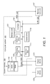
Fig. 1 shows one example of such aprogrammable computer system 101 capable of synchronizing service data between a telecommunication service provider and a data store associated with an end user of the service provider's telecommunication services. Thecomputer system 101 includes aprocessing unit 103, asystem memory 105, and a system bus 107 that couples various system components, including thesystem memory 105, to theprocessing unit 103. Thesystem memory 105 may include a read-only memory (ROM) 109 and a random access memory (RAM) 111. - A basic input/output system 113 (BIOS), containing the routines that help to transfer information between elements within the
computer system 101, such as during startup, may be stored in the read-only memory (ROM) 109. If thecomputer system 101 is embodied by a personal computer, it may further include ahard disk drive 115 for reading from and writing to a hard disk (not shown), amagnetic disk drive 117 for reading from or writing to a removable magnetic disk (not shown), or an optical disk drive 119 for reading from or writing to a removable optical disk (not shown) such as a CD-ROM or other optical media. - A number of program modules may be stored on the ROM 109, the
hard disk drive 115, themagnetic disk drive 117, and the optical disk drive 119. A user may enter commands and information into thecomputer system 101 through aninput device 123, such as a keyboard, a pointing device, a touch screen, a microphone, a joystick or any other suitable interface device. Of course, thecomputer system 101 may employ a variety ofdifferent input devices 123, as is known in the art. Anoutput device 125, such as a monitor or other type of display device, is also included to convey information from thecomputer system 101 to the user. As will be appreciated by those of ordinary skill in the art, a variety ofoutput devices 125, such as speakers and printers, may alternately or additionally be included in thecomputer system 101. - In order to access both the computing systems employed by one or more service providers and one or more data stores associated with an end user, the
computer system 101 preferably is capable of operating in a networked environment using logical connections to one or more remote computers, such as theremote computer 127. Thecomputer system 101 may be connectable to theremote computer 127 through a local area network (LAN) 129 or a wide area network (WAN) 131, such as the Internet. When used in a'networking environment, thecomputer system 101 may be connected to the network through an interlace 133, such as a wireless transceiver, a modem, an Ethernet connection, or any other such interface. While the interface 133 is illustrated as an internal interface inFig. 1 , it may alternately be an external interface as is well known in the art. Of course, it will be appreciated that the networks connections shown in this figure are exemplary, and other means of establishing a communications 1in!c with other computers to access an electronic mail account may be used. -
Fig. 2 illustrates anetwork 201 of devices that include anadaptive synchronization device 203. Thenetwork 201 also includes a variety of service provider (or service carrier) infrastructure sytems 205. As is known in the art, these service provider infrastructure sytems 205 are used to provide telecommunication services to a variety of telecommunication devices 207 employed by anend user 209. For example, the serviceprovider infrastructure system 205A may be a wireless application protocol gateway that communicates with a wireless telecommunication device, such as a wireless telephone or personal information manager, using the wireless mark-up language (WML), the hand-held device mark-up language (HDML), or another suitable communication language. - Similarly, the service
provider infrastructure system 205B may be a packet data gateway for transmitting and receiving information to, e.g., a mobile personal information manager such as a Palm or a Pocket PC-based computing device. Thepacket data gateway 205B may communicate with the mobile personalinformation management device 207B using any suitable communication method, such as a binary synchronization process or an extensible mark-up language (XML). Still further, as shown inFig. 2 , the serviceprovider infrastructure system 205C may be a voice services platform for transmitting voice messages to and receiving voice messages from awireless telephone 207C. In addition, thenetwork 201 may include one or more service provider service data stores 211. As known in the art, these service data stores 211 (e,g., Internet electronic mail servers) store service data used by service carriers to provide telecommunication services, such as electronic mail services, to theend user 209. - Referring back to
Fig. 2 , theadoptive synchronization device 203 is included in asubnetwork 213 associated with theend user 209. For example, thesubnetwork 213 3 may be a network maintained by the end user's employer or any other institution with which the end user is associated, such as a school, research center, or the like. Thesubnetwork 213 includes adata store 215 that stores data associated with theend user 209. Thus, thedata store 215 may store data used by a Microsoft Exchange® server or a Lotus Domino® server that contains contact information associated with theend user 209. If theend user 209 is a sales representative for an employer that maintainssubnetwork 213, then thedata store 215 may, e.g., include the name, telephone number, electronic mail address, and other address information relating to sales prospects of the employer. Thesubnetwork 213 may also include afirewall 217 to protect thesubnetwork 213 from unauthorized access. Such firewalls are well known in the art, and thus will not be described here in detail. - As will be explained in detail below, the
adaptive synchronization device 203 synchronizes the end user's service data stored in thedata store 215 on one side of thefirewall 217 with service data for theend user 209 stored in a synchronizationservice data store 219 maintained on an opposite side offirewall 217. As seen inFig. 2 , the synchronizationservice data store 219 provides service data to the service provider infrastructure systems 205 and the service provider data stores 211. Using this arrangement, the service providers can employ service data stored behind thefirewall 217 indata store 215 without having to actually penetrate thefirewall 217. Instead, the service provider infrastructure systems 205 and the serviceprovider data stores 211 can directly access the service data from the synchronizationservice data store 219. -
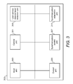
Fig. 3 illustrates theadaptive synchronization device 203 in more detail. As seen in this figure, theadaptive synchronization device 203 includes acontrol unit 301, aninput unit 303, and anoutput unit 305. Theadaptive synchronization device 203 also includes asynchronization process unit 307, a user service dataaccess detection unit 309, and asynchronization adaptation unit 311. Thecontrol unit 301 operates to control the exchange of information between each of the other control units 303-311. - As will be appreciated by those of ordinary skill in the art, one or more components of the
adaptive synchronization device 203 can be embodied using software implemented on a computer system, such as thecomputer system 101 described with regard toFig. 1 above. For example, theinput unit 303, theoutput unit 305, thesynchronization process unit 307, the user service dataaccess detection unit 309, and thesynchronization adaptation unit 311 can each be embodied by software subroutines. Thecontrol unit 301 may then be a control software routine that calls the various software subroutines embodying thedifferent units 303..311. Of course, those of ordinary skill in the art will appreciate that one or more of the units 301-311 may also be embodied by electronic circuitry. - The
input unit 303 receives information provided from outside of theadaptive synchronization device 203. For example, theinput unit 303 may receive messages from the synchronizationservice data store 219 or receive service data from the data store 315. Similarly, theoutput unit 305 transmits information to devices outside of theadaptive synchronization device 203. Thus, theoutput unit 203 may transmit control messages to the synchronizationservice data store 219, transmit request messages requesting information from the data store 315, and transmit service data received by theinput unit 303 from the data store 315 to the synchronizationservice data store 219. The operation of theinput unit 303 andoutput unit 305 are known in the art, and thus will not be discussed in here detail. - The
synchronization unit 307 controls the synchronization of data between thedata store 215 and the synchronization service data store 2I9. That is, thesynchronization unit 307 operates to ensure that a user's service data stored in the synchronizationservice data store 219 is synchronized with the user's service data stored in thedata store 215. Thus, if thedata store 215 contains new user service data (or a new deletion of the user's service data) that is not stored in the synchronizationservice data store 219, then thesynchronization unit 307 updates the synchronizationservice data store 219 to include the new data (or new deletion of data) during a synchronization process. Similarly, if the synchronizationservice data store 219 contains new user service data (or a new deletion of the user's service data) added by the user's use of the service provider's telecommunication services that is not stored in thedata store 215, then thesynchronization unit 307 updates the data store 21S to include the new data (or new deletion of data) during a synchronization process. - Accordingly, the
synchronization unit 307 may instruct theoutput unit 305 to transmit a request for the service data to thedata store 215, instruct theinput unit 303 to receive the requested service data from thedata store 215, and then instruct theoutput unit 305 to forward the received service data to the synchronizationservice data store 219. Alternately, thesynchronization unit 307 may control a synchronization process that operates outside of the adaptive synchronization device 203 (e.g., a synchronization process involving direct communication between thedata store 215 and the synchronizationservice data store 219, or involving another intermediary device between thedata store 215 and the synchronization service data store 219). - The user service data
retrieval detection unit 309 detects the retrieval of service data for theend user 209 from the synchronizationservice data store 219. More particularly, the user service dataretrieval detection unit 309 detects the retrieval of service data for a user by a service provider infrastructure system 205 or a service providerservice data store 211. According to some embodiments of the invention, the user service dataretrieval detection unit 309 detects and records the occurrence of each retrieval of service data associated with theend user 209 from the synchronizationservice data store 219. With alternate embodiments of the invention, the user service dataretrieval detection unit 309 detects and records the quantity of retrieved service data each time that service data associated with theend user 209 is retrieved from the synchronizationservice data store 219. According to still other embodiments of the invention, the user service dataretrieval detection unit 309 detects and records both the occurrence of each retrieval of service data associated with theend user 209 and the quantity of service data retrieved. - The
synchronization adaptation unit 311 then employs the information obtained by the user service dataretrieval detection unit 309 to determine the retrieval amount of the user's service data from the synchronizationservice data store 219, and whether the retrieval amount has increased or decreased. It should be noted that thesynchronization adaptation unit 311 may determine the retrieval amount in a variety of ways. For example, with some embodiments of the invention, thesynchronization adaptation unit 311 determines the retrievals amount based upon the frequency of retrieval of the user's service data in the synchronizationservice data store 219. - Further, if the
synchronization adaptation unit 311 determines the retrieval amount of the user's service data based upon the frequency at which the service data has been retrieved, the frequency value may also be determined in a variety of ways. For example, thesynchronization adaptation unit 311 can determine the service data retrieval frequency based solely upon the two most recent retrievals of the user's service data from the synchronizationservice data store 219. Thus, if the serviceprovider infrastructure system 205A made a first request for service data for the user at 1:130 A.M., the serviceprovider infrastructure system 205B made a second request for service data for the user at 1:30 A.M. and the serviceprovider infrastructure system 205C made a third request for service data for the user at 1:45 A.M., then thesynchronization adaptation unit 311 would determine the frequency of access to the user's service data to be once every 15 minutes. - Alternately, the
synchronization adaptation unit 311 could determine the retrieval frequency by averaging together the intervals between a predetermined number of retrievals requested from the synchronizationservice data store 219. Thus, if thesynchronization adaptation unit 311 determines the retrieval frequency by averaging together the intervals between the three most recent retrieval requests for service data for a user, thensynchronization adaptation unit 311 would determine a retrieval frequency of 22.5 minutes by averaging the interval between the first request and the second request (i.e., 30 minutes) with the interval between the second request and the third request (i.e., 15 nzinutes). Still further, thesynchronization adaptation unit 311 1 could determine the retrieval frequency based upon the number of requests for service data for a user received during a predetermined time period, e.g., each hour. With this embodiment, for the above example, thesynchronization adaptation unit 311 would determine the retrieval frequency to be every twenty minutes (i.e., the average of three retrieval requests within 60 minutes). - In alternate embodiments of the invention, the
synchronization adaptation unit 311 1 may determine the retrieval amount of the user's service data based upon the quantity of service data retrieved from the synchronizationservice data store 219. As before, the quantity of retrieved service data can be measured in a variety of ways. Thus, the quantity value can be defined by using individually retrieved record fields of the service data, based upon a specified window of time over which the retrieved service data was accumulated, or by using the number of records retrieved from the synchronizationservice data store 219. - For example, if the retrieved service data for the user is electronic mail messages, the value of the quantity of retrieved service data could be determined based upon the number of retrieved electronic mail file folders. With alternate embodiments of the invention, the value of the quantity of retrieved service data could be determine based upon the specific period of time (e.g., five days) over which the retrieved messages were received. For still other embodiments of the invention, the value of the quantity of retrieved service data could be determined based simply upon the number of retrieved messages (e.g., 50 electronic mail messages). As will be appreciated by those of ordinary skill in the art, the particular method for determining the quantity of the retrieved service data for a user can be determined according to any technique suitable to the desired application of the invention.
- In still other embodiments of the invention, the
synchronization adaptation unit 311 1 may determine the retrieval amount based on selection events initiated by the user. For example, if a user unsuccessfully attempts to select data, such as an e-mail message or appointment that falls outside of the currently synchronized amount (e.g., where such an amount is initially determined by, for example, a date range relative to the then-current date), then thesynchronization adaptation unit 311 may immediately adjust the applicable data amount for the user to ensure that a subsequent request for the data will be successful. When doing so, thesynchronization adaptation unit 311 1 may also communicate to the user that the adjustment has been made and when, based on the then-current interval, the user should reattempt the request. Other various embodiments of the invention may even adjust the data amount on a predictive basis before an unsuccessful data request actually occurs. For example, if the user has made multiple requests for data in a short period of time where such data fall close to the then-current "boundary" for that particular data type, then thesynchronization adaptation unit 311 may pro-actively adjust the boundary on the assumption that a spike in activity near a "boundary" is an indicator that a request for data beyond the "boundary" is more likely to occur. Thesynchronization adaptation unit 311 may then readjust the data amount if this activity pattern subsides. - According to still other embodiments of the invention, the
synchronization adaptation unit 311 may determine the amount of retrieved service data for the user based upon both the frequency of retrieval requests and the quantity of data obtained during each retrieval. Thus, thesynchronization adaptation unit 311 may determine both a retrieval frequency value and a retrieved service data quantity value. Alternately, thesynchronization adaptation unit 311 may determine a single retrieval amount value using both a determined retrieval frequency and a determined of quantity of retrieved service data. For example, thesynchronization adaptation unit 311 may multiply a determined retrieval frequency by a first constant, multiply a determined retrieval quantity by a second constant, and then add the two resulting values to obtain a single service data retrieval amount value. Again, as will appreciated by those of ordinary skill in the art, the particular method for determining a retrieval amount of retrieved service data for a user can be determined by using any suitable technique appropriate to the desired application of the invention. - As previously noted, the
synchronization adaptation unit 311. also determines whether the determined retrieval amount of retrieved service data for a user is an increase or a decrease over the previously determined retrieval amount of retrieved service data for the user. Thus, if thesynchronization adaptation unit 311 determines the retrieval amount to be the retrieval frequency based upon the interval between the most receipt two retrieval requests, then for the above example (using the first, second and third requests) thesynchronization adaptation unit 311 will determine a first retrieval frequency of one per thirty minutes, and a second retrieval frequency of one per fifteen minutes. With this example, thesynchronization adaptation unit 311 would then determine that the second retrieval frequency, and thus the retrieval amount, has increased over the first retrieval frequency. - In addition to determining the retrieval amount of retrieved service data for a user and whether this retrieval amount is an increase or a decrease over the previously determined retrieval amount, the
synchronization adaptation unit 311 also determines the synchronization amount for synchronizing service data between thedata store 215 and the synchronizationservice data store 219. More particularly, thesynchronization adaptation unit 311 determines the synchronization amount based upon the whether the determined retrieval amount has increased or decreased over previously determined retrievals amounts. - As used herein, the term synchronization amount includes any synchronization parameter that, when increased, improves the operation of the synchronization process (e.g., the quantity of data synchronized during a synchronization process). The term synchronization amount includes the inverse of any synchronization parameter that, when decreased, improves the operation of the synchronization process (e.g., the inverse of the interval between synchronization processes, or the synchronization frequency).
- Thus
synchronization adaptation unit 311 can determine the synchronization amount according to a variety of techniques. For some embodiments of the invention, thesynchronization adaptation unit 311 determines the synchronization amount to be the frequency at which the user's service data stored in thedata store 215 is synchronized with the user's service data stored in the synchronizationservice data store 219. According to still other embodiments of the invention, the synchronization amount is the quantity of service data synchronized between thedata store 215 and the synchronizationservice data store 219 during a synchronization process. With still further embodiments of the invention, the synchronization amount includes both the quantity of service data synchronized between thedata store 215 and the synchronizationservice data store 219 and the frequency of synchronization. Of course, the synchronization amount may also be or include other synchronization parameters (or their inverses) as desirable for the particular application of the invention. - It should be noted that the
synchronization adaptation unit 311 can determine the synchronization amount based upon an increase or decrease of any type of determined retrieval amount. Thus, thesynchronization adaptation unit 311 can use an increase or decrease in a retrieval amount that includes both the retrieval frequency and the quantity of retrieved service data to determine a synchronization amount that includes both the frequency of synchronization and the quantity of synchronized service data. With this example, thesynchronization adaptation unit 311 can increase the synchronization frequency when the retrieval frequency increases, and decrease the synchronization frequency when the retrieval frequency decreases. Similarly, thesynchronization adaptation unit 311 can increase the quantity of synchronized service data when the quantity of retrieved service data increases, and decrease the quantity of synchronized service data when the quantity of retrieved service data decreases. - With still other embodiments of the invention, the
synchronization adaptation unit 311 can use an increase or decrease in a retrieval amount that includes both the retrieval frequency and the quantity of retrieved service data to determine a synchronization amount that includes only the frequency of synchronization, or only the quantity of synchronized service data. In alternate embodiments of invention, thesynchronization adaptation unit 311 can use an increase or decrease in a retrieval amount that includes only the retrieval frequency or only the quantity of retrieved service data to determine a synchronization amount that includes both the frequency of synchronization and the quantity of synchronized service data. As will be appreciated by those of ordinary skill in the art upon a review of this application, an increase or decrease in any combination of types of retrieval amount values can be used to determine an increase or decrease in any combination of types of synchronization amount values, as appropriate for the desired application of the invention. - It should also be noted that the
synchronization adaptation unit 311 can determines the specific increase or decrease in the synchronization amount according to a variety of techniques. According to some embodiments of the invention, for example, thesynchronization adaptation unit 311 increases the synchronization amount based upon an increase in the retrieval amount according to the lower half of a bell curve, such as the half bell curve shown inFig. 4 . - As seen in this figure, the degree to which the synchronization amount is increased significantly as the value of the retrieval amount increases from zero to a threshold value X. Then, as the value of the retrieval amount continues to increase from the threshold value X to a maximum, the degree to which the synchronization amount is increased declines to zero. For example, a "light" end user whose telecommunication use requires his or her service provider to have a relatively low service data retrieval amount for the user's service data may have an initial synchronization interval of 45 minutes. As the user's service data retrieval amount increased, the
synchronization adaptation unit 311 might then cut the synchronization by a third to 15 minutes, and then, with a still increased retrieval amount, again by a third, to a five-minute synchronization interval. - Advantageously, this arrangement accounts for abrupt changes in user behavior. One such change in behavior that is particularly risky is the "trade show effect," or light users who on occasion quickly become heavy users for short periods of time (the risk being that they have a poor user experience because the synchronization parameters have adjusted to be very high). For example, an end user who is a product manager for his or her employer may generally be a light user (i.e., who requires his or her service provider to infrequently retrieve his or her service data from the synchronization service data store 291), but relies rather heavily on the service provider's telecommunication services when on the road for trade shows. While at the trade shows, the user will experience evident service data synchronization deficiencies only initially, because, according to the invention, the service data synchronization amount increases the more the telecommunication services are used.
- According to some embodiments of the invention, the
synchronization adaptation unit 311 will also decrease the synchronization amount according to a rate corresponding to one half of a bell curve. Thus, even if the carrier chooses to cut the synchronization amount (e.g., the synchronization interval) dramatically after an end user's first usage of the service data (thereby quickly improving the user's experience), its costs will not significantly increase because the synchronization amount will readjust to become smaller as the user stops using the device. Only that short interval of time will have entailed high costs to the provider, and the total cost over time is much lower than if, e.g., the frequency of synchronization were constant. It should be noted that the bell curve may be that same as the bell curve governing the increase rate. Alternately, thesynchronization adaptation unit 311 may provide a hysteresis effect by employing a different bell curve than the rate of synchronization amount increase, or by decreasing the synchronization amount according to a different rate pattern altogether - The present invention has been described above by way of specific exemplary embodiments, and the many features and advantages of the present invention are apparent from the written description. Thus, it is intended that the appended claims cover all such features and advantages of the invention. Further, because numerous modifications and changes will readily occur to those skilled in the art, the specification is not intended to limit the invention to the exact construction and operation as illustrated and described. For example, the invention may include any one or more elements from the apparatus and methods described herein in any combination or subcombination. Accordingly, there are any number of alternative combinations for defining the invention, which incorporate one or more elements from the specification (including the drawings, claims, and summary of the invention) in any combinations or subcombinations. Hence, all suitable modification and equivalents may be considered as falling within the scope of the appended claims.
- The following numbered clauses form a part of the_present disclosure and describe embodiments of the present invention.
- 1. A method of synchronizing service data for a user, comprising:
- detecting an increase in frequency of use of service data by a service provider on behalf of the user; and
- when an increase in frequency of use of service data by a service provider on behalf of the user has been detected, increasing a frequency of synchronization of service data between the service provider and a data storage device associated with the user.
- 2. The method of synchronizing service data for a user recited in clause 1, further including:
- detecting a decrease in frequency of use of service data by a service provider on behalf of the user; and
- when a decrease in frequency of use of service data by a service provider on behalf of the user has been detected, decreasing a frequency of synchronization of service data between the service provider and a data storage device associated with the user.
- 3. The method of synchronizing service data for a user recited in clause 2, wherein the frequency of synchronization of service data is decreased by an increasing amount for each decrease in frequency of use of service data below a threshold value and decreased by an decreasing amount for each decrease in frequency of use of service data above the threshold value.
- 4. The method of synchronizing service data for a user recited in clause 1, wherein the frequency of synchronization of service data is increased by an increasing amount for each increase in frequency of use of service data below a threshold value and increased by a decreasing amount for each increase in frequency of use of service data above the threshold value.
- 5. The method of synchronizing service data for a user recited in clause 1, further including:
- when an increase in frequency of use of service data by a service provider on behalf of the user has been detected, increasing a quantity of service data synchronized during synchronization of service data between the service provider and a data storage device associated with the user.
- 6. The method of synchronizing service data for a user recited in clause 5, wherein the quantity of service data synchronized during synchronization of service data is increased by an increasing amount for each increase in frequency of use of service data below a threshold value and increased by a decreasing amount for each increase in frequency of use of service data above the threshold value.
- 7. The method of synchronizing service data for a user recited in clause 5, further including:
- detecting a decrease in frequency of use of service data by a service provider on behalf of the user; and
- when a decrease in frequency of use of service data by a service provider on behalf of the user has been detected, decreasing a quantity of service data synchronized during synchronization of service data between the service provider and a data storage device associated with the user.
- 8. The method of synchronizing service data for a user recited in clause 7, wherein the quantity of service data synchronized during synchronization of service data is decreased by an increasing amount for each decrease in frequency of use of service data below a threshold value and decreased by an decreasing amount for each decrease in frequency of use of service data above the threshold value.
- 9. The method of synchronizing service data for a user recited in clause 1, wherein the data storage device associated with the user is an institutional database maintained by an institution associated with the user.
- 10. The method of synchronizing service data for a user recited in clause 9, wherein the data storage device associated with the user is a corporate data store maintained by an employer of the user.
- 11. The method of synchronizing service data for a user recited in clause 9, wherein the data store is a Microsoft Exchange® database or a Lotus Notes® database.
- 12. A method of synchronizing service data for a user, comprising:
- detecting an increase in a quantity of service data used by a service provider on behalf of the user; and
- when an increase in a quantity of service data used by a service provider on behalf of the user has been detected, increasing a quantity of service data synchronized during synchronization of service data between the service provider and a data storage device associated with the user.
- 13. The method of synchronizing service data for a user recited in clause 12, further including:
- detecting a decrease in a quantity of service data used by a service provider on behalf of the user; and
- when a decrease in a quantity of service data used by a service provider on behalf of the user has been detected, decreasing a quantity of service data synchronized during synchronization of service data between the service provider and a data storage device associated with the user.
- 14. The method of synchronizing service data for a user recited in clause 13, wherein the quantity of service data synchronized during synchronization of service data is decreased by an increasing amount for each decrease in quantity of service data used by the service provider below a threshold value and decreased by an decreasing amount of each decrease in quantity of service data used by the service provider above the threshold value.
- 15. The method of synchronizing service data for a user recited in clause 12, wherein the quantity of service data synchronized during synchronization of service data is increased by an increasing amount for each increase in quantity of service data used by the service provider below a threshold value and increased by a decreasing amount for each increase in quantity of service data used by the service provider above the threshold value.
- 16. The method of synchronizing service data for a user recited in clause 12, further including:
- when an increase in quantity of service data used by the service provider on behalf of the user has been detected, increasing a frequency of synchronization of service data between the service provider and a data storage device associated with the user.
- 17. The method of synchronizing service data for a user recited in clause 16, wherein the frequency of synchronization of service data is increased by an increasing amount for each increase in quantity of service data used by the service provider below a threshold value and increased by a decreasing amount for each increase in quantity of service data used by the service provider above the threshold value.
- 18. The method of synchronizing service data for a user recited in clause 16, further including:
- detecting a decrease in quantity of service data used by the service provider on behalf of the user; and
- when a decrease in quantity of service data used by the service provider on behalf of the user has been detected, decreasing a frequency of synchronization of service data between the service provider and a data storage device associated with the user.
- 19. The method of synchronizing service data for a user recited in clause 18, wherein the frequency of synchronization of service data is decreased by an increasing amount for each decrease in quantity of service data used by the service provider below a threshold value and decreased by an decreasing amount for each decrease in quantity of service data used by the service provider above the threshold value.
- 20. The method of synchronizing service data for a user recited in clause 12, wherein the data storage device associated with the user is an institutional data store maintained by an institution associated with the user.
- 21. The method of synchronizing service data for a user recited in clause 20, wherein the data storage device associated with the user is a corporate data store maintained by an employer of the user.
- 22. The method of synchronizing service data for a user recited in clause 20, wherein the data store is a Microsoft Exchanger data store, a Microsoft Outlook data store, a Lotus Domino data store or a Lotus Notes® data store.
Claims (15)
Applications Claiming Priority (2)
| Application Number | Priority Date | Filing Date | Title |
|---|---|---|---|
| US37696202P | 2002-04-30 | 2002-04-30 | |
| EP03726541A EP1502199B1 (en) | 2002-04-30 | 2003-04-30 | Adaptive synchronization of service data |
Related Parent Applications (1)
| Application Number | Title | Priority Date | Filing Date |
|---|---|---|---|
| EP03726541.0 Division | 2003-04-30 |
Publications (2)
| Publication Number | Publication Date |
|---|---|
| EP2207328A1 true EP2207328A1 (en) | 2010-07-14 |
| EP2207328B1 EP2207328B1 (en) | 2013-03-20 |
Family
ID=29401427
Family Applications (2)
| Application Number | Title | Priority Date | Filing Date |
|---|---|---|---|
| EP03726541A Expired - Lifetime EP1502199B1 (en) | 2002-04-30 | 2003-04-30 | Adaptive synchronization of service data |
| EP09175614A Expired - Lifetime EP2207328B1 (en) | 2002-04-30 | 2003-04-30 | Adaptive synchronization of service data |
Family Applications Before (1)
| Application Number | Title | Priority Date | Filing Date |
|---|---|---|---|
| EP03726541A Expired - Lifetime EP1502199B1 (en) | 2002-04-30 | 2003-04-30 | Adaptive synchronization of service data |
Country Status (10)
| Country | Link |
|---|---|
| EP (2) | EP1502199B1 (en) |
| JP (1) | JP4588443B2 (en) |
| AT (1) | ATE448629T1 (en) |
| AU (1) | AU2003228771A1 (en) |
| CA (1) | CA2483887A1 (en) |
| DE (1) | DE60329998D1 (en) |
| ES (2) | ES2335487T3 (en) |
| IL (1) | IL164938A0 (en) |
| NO (1) | NO20045179L (en) |
| WO (1) | WO2003094029A1 (en) |
Cited By (2)
| Publication number | Priority date | Publication date | Assignee | Title |
|---|---|---|---|---|
| WO2015057536A1 (en) * | 2013-10-17 | 2015-04-23 | Microsoft Corporation | Data classification for adaptive synchronization |
| US9519490B2 (en) | 2013-03-07 | 2016-12-13 | Microsoft Technology Licensing, Llc | Adaptive data synchronization |
Families Citing this family (4)
| Publication number | Priority date | Publication date | Assignee | Title |
|---|---|---|---|---|
| US7395446B2 (en) * | 2004-05-03 | 2008-07-01 | Microsoft Corporation | Systems and methods for the implementation of a peer-to-peer rule-based pull autonomous synchronization system |
| US9380110B2 (en) | 2011-12-09 | 2016-06-28 | Google Technology Holdings LLC | Adaptive data synchronization based on data plan or network usage |
| US9477678B2 (en) | 2013-01-23 | 2016-10-25 | Htc Corporation | Data synchronization management methods and systems |
| WO2015072220A1 (en) * | 2013-11-14 | 2015-05-21 | ソニー株式会社 | Information processing device, information processing method, and storage medium |
Citations (2)
| Publication number | Priority date | Publication date | Assignee | Title |
|---|---|---|---|---|
| US5968131A (en) * | 1997-04-11 | 1999-10-19 | Roampage, Inc. | System and method for securely synchronizing multiple copies of a workspace element in a network |
| WO2002021777A1 (en) * | 2000-09-06 | 2002-03-14 | Xanboo, Inc. | Adaptive method for polling |
Family Cites Families (8)
| Publication number | Priority date | Publication date | Assignee | Title |
|---|---|---|---|---|
| US6006017A (en) * | 1995-05-02 | 1999-12-21 | Motorola Inc. | System for determining the frequency of repetitions of polling active stations relative to the polling of inactive stations |
| JP2000268053A (en) * | 1999-03-19 | 2000-09-29 | Nippon Steel Corp | Information sharing system, device and method for controlling access to information and recording medium |
| US6446090B1 (en) * | 1999-10-08 | 2002-09-03 | Unisys Corporation | Tracker sensing method for regulating synchronization of audit files between primary and secondary hosts |
| JP2001297023A (en) * | 2000-04-13 | 2001-10-26 | Packaging Technology:Kk | Database updating device |
| JP2002007192A (en) * | 2000-06-27 | 2002-01-11 | Mitsubishi Electric Corp | Method for updating data and system for the same |
| JP2001229066A (en) * | 2000-12-19 | 2001-08-24 | Mitsubishi Electric Corp | System and method for mirroring |
| US8402129B2 (en) * | 2001-03-21 | 2013-03-19 | Alcatel Lucent | Method and apparatus for efficient reactive monitoring |
| US20020174372A1 (en) * | 2001-05-18 | 2002-11-21 | Buvana Venkataraman | Method and apparatus for providing synchronized data |
-
2003
- 2003-04-30 EP EP03726541A patent/EP1502199B1/en not_active Expired - Lifetime
- 2003-04-30 ES ES03726541T patent/ES2335487T3/en not_active Expired - Lifetime
- 2003-04-30 JP JP2004502182A patent/JP4588443B2/en not_active Expired - Lifetime
- 2003-04-30 AT AT03726541T patent/ATE448629T1/en not_active IP Right Cessation
- 2003-04-30 WO PCT/US2003/013413 patent/WO2003094029A1/en active Search and Examination
- 2003-04-30 CA CA002483887A patent/CA2483887A1/en not_active Abandoned
- 2003-04-30 DE DE60329998T patent/DE60329998D1/en not_active Expired - Lifetime
- 2003-04-30 ES ES09175614T patent/ES2415740T3/en not_active Expired - Lifetime
- 2003-04-30 EP EP09175614A patent/EP2207328B1/en not_active Expired - Lifetime
- 2003-04-30 AU AU2003228771A patent/AU2003228771A1/en not_active Abandoned
-
2004
- 2004-10-31 IL IL16493804A patent/IL164938A0/en unknown
- 2004-11-26 NO NO20045179A patent/NO20045179L/en not_active Application Discontinuation
Patent Citations (2)
| Publication number | Priority date | Publication date | Assignee | Title |
|---|---|---|---|---|
| US5968131A (en) * | 1997-04-11 | 1999-10-19 | Roampage, Inc. | System and method for securely synchronizing multiple copies of a workspace element in a network |
| WO2002021777A1 (en) * | 2000-09-06 | 2002-03-14 | Xanboo, Inc. | Adaptive method for polling |
Non-Patent Citations (1)
| Title |
|---|
| WARD FOSTER ET AL: "Method for reducing polling traffic within a mailbox communication system", RESEARCH DISCLOSURE, MASON PUBLICATIONS, HAMPSHIRE, GB, vol. 468, no. 64, April 2003 (2003-04-01), XP007132506, ISSN: 0374-4353 * |
Cited By (8)
| Publication number | Priority date | Publication date | Assignee | Title |
|---|---|---|---|---|
| US9519490B2 (en) | 2013-03-07 | 2016-12-13 | Microsoft Technology Licensing, Llc | Adaptive data synchronization |
| US10491535B2 (en) | 2013-03-07 | 2019-11-26 | Microsoft Technology Licensing, Llc | Adaptive data synchronization |
| WO2015057536A1 (en) * | 2013-10-17 | 2015-04-23 | Microsoft Corporation | Data classification for adaptive synchronization |
| CN105637841A (en) * | 2013-10-17 | 2016-06-01 | 微软技术许可有限责任公司 | Data classification for adaptive synchronization |
| KR20160074489A (en) * | 2013-10-17 | 2016-06-28 | 마이크로소프트 테크놀로지 라이센싱, 엘엘씨 | Data classification for adaptive synchronization |
| US9588983B2 (en) | 2013-10-17 | 2017-03-07 | Microsoft Technology Licensing, Llc | Data classification for adaptive synchronization |
| CN105637841B (en) * | 2013-10-17 | 2018-11-30 | 微软技术许可有限责任公司 | The data classification synchronous for adaptability |
| KR102273414B1 (en) | 2013-10-17 | 2021-07-05 | 마이크로소프트 테크놀로지 라이센싱, 엘엘씨 | Data classification for adaptive synchronization |
Also Published As
| Publication number | Publication date |
|---|---|
| EP1502199A1 (en) | 2005-02-02 |
| CA2483887A1 (en) | 2003-11-13 |
| IL164938A0 (en) | 2005-12-18 |
| ES2415740T3 (en) | 2013-07-26 |
| JP2005524173A (en) | 2005-08-11 |
| AU2003228771A1 (en) | 2003-11-17 |
| DE60329998D1 (en) | 2009-12-24 |
| NO20045179L (en) | 2004-11-26 |
| ES2335487T3 (en) | 2010-03-29 |
| WO2003094029A1 (en) | 2003-11-13 |
| EP2207328B1 (en) | 2013-03-20 |
| EP1502199B1 (en) | 2009-11-11 |
| ATE448629T1 (en) | 2009-11-15 |
| JP4588443B2 (en) | 2010-12-01 |
| EP1502199A4 (en) | 2007-05-02 |
Similar Documents
| Publication | Publication Date | Title |
|---|---|---|
| US8412805B2 (en) | Adaptive synchronization of service data | |
| US20210359967A1 (en) | System and method of a relay server for managing communications and notification between a mobile device and application server | |
| EP1557987B1 (en) | Electronic mailbox polling method | |
| EP2325743B1 (en) | Asynchronous real-time retrieval of data | |
| US7912896B2 (en) | Data access, replication or communication system comprising a distributed software application | |
| US7853652B2 (en) | Instant messaging system with privacy codes | |
| US20070130315A1 (en) | System and method for providing provisioning and upgrade services for a wireless device | |
| US20040143632A1 (en) | Method and system for publication of instant messaging privacy codes | |
| EP1531641B1 (en) | A server apparatus | |
| EP2207328B1 (en) | Adaptive synchronization of service data | |
| WO2004030308A1 (en) | Method for transferring, data, e.g. emails, from a computer protected by a firewall to an external device, e.g. a mobile terminal | |
| JP2002132716A (en) | Groupware system |
Legal Events
| Date | Code | Title | Description |
|---|---|---|---|
| PUAI | Public reference made under article 153(3) epc to a published international application that has entered the european phase |
Free format text: ORIGINAL CODE: 0009012 |
|
| 17P | Request for examination filed |
Effective date: 20091110 |
|
| AC | Divisional application: reference to earlier application |
Ref document number: 1502199 Country of ref document: EP Kind code of ref document: P |
|
| AK | Designated contracting states |
Kind code of ref document: A1 Designated state(s): AT BE BG CH CY CZ DE DK EE ES FI FR GB GR HU IE IT LI LU MC NL PT RO SE SI SK TR |
|
| RAP1 | Party data changed (applicant data changed or rights of an application transferred) |
Owner name: VISTO CORPORATION |
|
| 17Q | First examination report despatched |
Effective date: 20100709 |
|
| GRAP | Despatch of communication of intention to grant a patent |
Free format text: ORIGINAL CODE: EPIDOSNIGR1 |
|
| RAP1 | Party data changed (applicant data changed or rights of an application transferred) |
Owner name: GOOD TECHNOLOGY CORPORATION |
|
| GRAS | Grant fee paid |
Free format text: ORIGINAL CODE: EPIDOSNIGR3 |
|
| GRAA | (expected) grant |
Free format text: ORIGINAL CODE: 0009210 |
|
| AC | Divisional application: reference to earlier application |
Ref document number: 1502199 Country of ref document: EP Kind code of ref document: P |
|
| AK | Designated contracting states |
Kind code of ref document: B1 Designated state(s): AT BE BG CH CY CZ DE DK EE ES FI FR GB GR HU IE IT LI LU MC NL PT RO SE SI SK TR |
|
| REG | Reference to a national code |
Ref country code: GB Ref legal event code: FG4D |
|
| REG | Reference to a national code |
Ref country code: CH Ref legal event code: EP |
|
| REG | Reference to a national code |
Ref country code: IE Ref legal event code: FG4D |
|
| REG | Reference to a national code |
Ref country code: AT Ref legal event code: REF Ref document number: 602657 Country of ref document: AT Kind code of ref document: T Effective date: 20130415 |
|
| REG | Reference to a national code |
Ref country code: DE Ref legal event code: R096 Ref document number: 60343580 Country of ref document: DE Effective date: 20130508 |
|
| REG | Reference to a national code |
Ref country code: ES Ref legal event code: FG2A Ref document number: 2415740 Country of ref document: ES Kind code of ref document: T3 Effective date: 20130726 |
|
| PG25 | Lapsed in a contracting state [announced via postgrant information from national office to epo] |
Ref country code: SE Free format text: LAPSE BECAUSE OF FAILURE TO SUBMIT A TRANSLATION OF THE DESCRIPTION OR TO PAY THE FEE WITHIN THE PRESCRIBED TIME-LIMIT Effective date: 20130320 Ref country code: BG Free format text: LAPSE BECAUSE OF FAILURE TO SUBMIT A TRANSLATION OF THE DESCRIPTION OR TO PAY THE FEE WITHIN THE PRESCRIBED TIME-LIMIT Effective date: 20130620 |
|
| REG | Reference to a national code |
Ref country code: NL Ref legal event code: T3 |
|
| REG | Reference to a national code |
Ref country code: AT Ref legal event code: MK05 Ref document number: 602657 Country of ref document: AT Kind code of ref document: T Effective date: 20130320 |
|
| PG25 | Lapsed in a contracting state [announced via postgrant information from national office to epo] |
Ref country code: GR Free format text: LAPSE BECAUSE OF FAILURE TO SUBMIT A TRANSLATION OF THE DESCRIPTION OR TO PAY THE FEE WITHIN THE PRESCRIBED TIME-LIMIT Effective date: 20130621 Ref country code: FI Free format text: LAPSE BECAUSE OF FAILURE TO SUBMIT A TRANSLATION OF THE DESCRIPTION OR TO PAY THE FEE WITHIN THE PRESCRIBED TIME-LIMIT Effective date: 20130320 Ref country code: SI Free format text: LAPSE BECAUSE OF FAILURE TO SUBMIT A TRANSLATION OF THE DESCRIPTION OR TO PAY THE FEE WITHIN THE PRESCRIBED TIME-LIMIT Effective date: 20130320 |
|
| PG25 | Lapsed in a contracting state [announced via postgrant information from national office to epo] |
Ref country code: BE Free format text: LAPSE BECAUSE OF FAILURE TO SUBMIT A TRANSLATION OF THE DESCRIPTION OR TO PAY THE FEE WITHIN THE PRESCRIBED TIME-LIMIT Effective date: 20130320 |
|
| PG25 | Lapsed in a contracting state [announced via postgrant information from national office to epo] |
Ref country code: RO Free format text: LAPSE BECAUSE OF FAILURE TO SUBMIT A TRANSLATION OF THE DESCRIPTION OR TO PAY THE FEE WITHIN THE PRESCRIBED TIME-LIMIT Effective date: 20130320 Ref country code: PT Free format text: LAPSE BECAUSE OF FAILURE TO SUBMIT A TRANSLATION OF THE DESCRIPTION OR TO PAY THE FEE WITHIN THE PRESCRIBED TIME-LIMIT Effective date: 20130722 Ref country code: AT Free format text: LAPSE BECAUSE OF FAILURE TO SUBMIT A TRANSLATION OF THE DESCRIPTION OR TO PAY THE FEE WITHIN THE PRESCRIBED TIME-LIMIT Effective date: 20130320 Ref country code: EE Free format text: LAPSE BECAUSE OF FAILURE TO SUBMIT A TRANSLATION OF THE DESCRIPTION OR TO PAY THE FEE WITHIN THE PRESCRIBED TIME-LIMIT Effective date: 20130320 Ref country code: CZ Free format text: LAPSE BECAUSE OF FAILURE TO SUBMIT A TRANSLATION OF THE DESCRIPTION OR TO PAY THE FEE WITHIN THE PRESCRIBED TIME-LIMIT Effective date: 20130320 Ref country code: SK Free format text: LAPSE BECAUSE OF FAILURE TO SUBMIT A TRANSLATION OF THE DESCRIPTION OR TO PAY THE FEE WITHIN THE PRESCRIBED TIME-LIMIT Effective date: 20130320 |
|
| PG25 | Lapsed in a contracting state [announced via postgrant information from national office to epo] |
Ref country code: CY Free format text: LAPSE BECAUSE OF FAILURE TO SUBMIT A TRANSLATION OF THE DESCRIPTION OR TO PAY THE FEE WITHIN THE PRESCRIBED TIME-LIMIT Effective date: 20130320 |
|
| REG | Reference to a national code |
Ref country code: CH Ref legal event code: PL |
|
| PG25 | Lapsed in a contracting state [announced via postgrant information from national office to epo] |
Ref country code: MC Free format text: LAPSE BECAUSE OF FAILURE TO SUBMIT A TRANSLATION OF THE DESCRIPTION OR TO PAY THE FEE WITHIN THE PRESCRIBED TIME-LIMIT Effective date: 20130320 |
|
| PGFP | Annual fee paid to national office [announced via postgrant information from national office to epo] |
Ref country code: IT Payment date: 20130424 Year of fee payment: 11 |
|
| PLBE | No opposition filed within time limit |
Free format text: ORIGINAL CODE: 0009261 |
|
| STAA | Information on the status of an ep patent application or granted ep patent |
Free format text: STATUS: NO OPPOSITION FILED WITHIN TIME LIMIT |
|
| REG | Reference to a national code |
Ref country code: IE Ref legal event code: MM4A |
|
| PG25 | Lapsed in a contracting state [announced via postgrant information from national office to epo] |
Ref country code: LI Free format text: LAPSE BECAUSE OF NON-PAYMENT OF DUE FEES Effective date: 20130430 Ref country code: CH Free format text: LAPSE BECAUSE OF NON-PAYMENT OF DUE FEES Effective date: 20130430 Ref country code: DK Free format text: LAPSE BECAUSE OF FAILURE TO SUBMIT A TRANSLATION OF THE DESCRIPTION OR TO PAY THE FEE WITHIN THE PRESCRIBED TIME-LIMIT Effective date: 20130320 |
|
| 26N | No opposition filed |
Effective date: 20140102 |
|
| REG | Reference to a national code |
Ref country code: DE Ref legal event code: R097 Ref document number: 60343580 Country of ref document: DE Effective date: 20140102 |
|
| PG25 | Lapsed in a contracting state [announced via postgrant information from national office to epo] |
Ref country code: IE Free format text: LAPSE BECAUSE OF NON-PAYMENT OF DUE FEES Effective date: 20130430 |
|
| PG25 | Lapsed in a contracting state [announced via postgrant information from national office to epo] |
Ref country code: IT Free format text: LAPSE BECAUSE OF NON-PAYMENT OF DUE FEES Effective date: 20140430 |
|
| REG | Reference to a national code |
Ref country code: ES Ref legal event code: FD2A Effective date: 20150527 |
|
| PG25 | Lapsed in a contracting state [announced via postgrant information from national office to epo] |
Ref country code: TR Free format text: LAPSE BECAUSE OF FAILURE TO SUBMIT A TRANSLATION OF THE DESCRIPTION OR TO PAY THE FEE WITHIN THE PRESCRIBED TIME-LIMIT Effective date: 20130320 |
|
| PG25 | Lapsed in a contracting state [announced via postgrant information from national office to epo] |
Ref country code: LU Free format text: LAPSE BECAUSE OF NON-PAYMENT OF DUE FEES Effective date: 20130430 Ref country code: ES Free format text: LAPSE BECAUSE OF NON-PAYMENT OF DUE FEES Effective date: 20140501 Ref country code: HU Free format text: LAPSE BECAUSE OF FAILURE TO SUBMIT A TRANSLATION OF THE DESCRIPTION OR TO PAY THE FEE WITHIN THE PRESCRIBED TIME-LIMIT; INVALID AB INITIO Effective date: 20030430 |
|
| REG | Reference to a national code |
Ref country code: FR Ref legal event code: PLFP Year of fee payment: 14 |
|
| REG | Reference to a national code |
Ref country code: GB Ref legal event code: 732E Free format text: REGISTERED BETWEEN 20170331 AND 20170405 Ref country code: FR Ref legal event code: PLFP Year of fee payment: 15 |
|
| REG | Reference to a national code |
Ref country code: DE Ref legal event code: R081 Ref document number: 60343580 Country of ref document: DE Owner name: GOOD TECHNOLOGY HOLDINGS LTD., WATERLOO, CA Free format text: FORMER OWNER: GOOD TECHNOLOGY CORP., DOVER, DELAWARE, US Ref country code: DE Ref legal event code: R081 Ref document number: 60343580 Country of ref document: DE Owner name: BLACKBERRY LIMITED, WATERLOO, CA Free format text: FORMER OWNER: GOOD TECHNOLOGY CORP., DOVER, DELAWARE, US |
|
| REG | Reference to a national code |
Ref country code: FR Ref legal event code: TP Owner name: GOOD TECHNOLOGY HOLDINGS LIMITED, CA Effective date: 20170613 |
|
| REG | Reference to a national code |
Ref country code: DE Ref legal event code: R082 Ref document number: 60343580 Country of ref document: DE Representative=s name: MERH-IP MATIAS ERNY REICHL HOFFMANN PATENTANWA, DE Ref country code: DE Ref legal event code: R081 Ref document number: 60343580 Country of ref document: DE Owner name: BLACKBERRY LIMITED, WATERLOO, CA Free format text: FORMER OWNER: GOOD TECHNOLOGY HOLDINGS LTD., WATERLOO, ONTARIO, CA |
|
| REG | Reference to a national code |
Ref country code: FR Ref legal event code: PLFP Year of fee payment: 16 |
|
| REG | Reference to a national code |
Ref country code: NL Ref legal event code: PD Owner name: BLACKBERRY LIMITED; CA Free format text: DETAILS ASSIGNMENT: CHANGE OF OWNER(S), ASSIGNMENT; FORMER OWNER NAME: GOOD TECHNOLOGY HOLDINGS LIMITED Effective date: 20180306 |
|
| REG | Reference to a national code |
Ref country code: GB Ref legal event code: 732E Free format text: REGISTERED BETWEEN 20180524 AND 20180530 |
|
| REG | Reference to a national code |
Ref country code: DE Ref legal event code: R079 Ref document number: 60343580 Country of ref document: DE Free format text: PREVIOUS MAIN CLASS: H04L0029080000 Ipc: H04L0065000000 |
|
| PGFP | Annual fee paid to national office [announced via postgrant information from national office to epo] |
Ref country code: NL Payment date: 20220426 Year of fee payment: 20 |
|
| PGFP | Annual fee paid to national office [announced via postgrant information from national office to epo] |
Ref country code: GB Payment date: 20220427 Year of fee payment: 20 Ref country code: FR Payment date: 20220425 Year of fee payment: 20 Ref country code: DE Payment date: 20220427 Year of fee payment: 20 |
|
| REG | Reference to a national code |
Ref country code: DE Ref legal event code: R071 Ref document number: 60343580 Country of ref document: DE |
|
| REG | Reference to a national code |
Ref country code: NL Ref legal event code: MK Effective date: 20230429 |
|
| REG | Reference to a national code |
Ref country code: GB Ref legal event code: PE20 Expiry date: 20230429 |
|
| PG25 | Lapsed in a contracting state [announced via postgrant information from national office to epo] |
Ref country code: GB Free format text: LAPSE BECAUSE OF EXPIRATION OF PROTECTION Effective date: 20230429 |